1
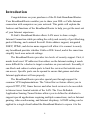
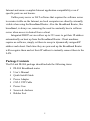
D-Link DI-804 Broadband Router User’s Manual Rev.01 ( March,2001 ) 6RDI804…01 Contents Introduction ................................................................................................4 Package Contents......................................................................................5 Introduction to Broadband Router Technology ........................................6 Introduction to Firewalls ..........................................................................6 Introduction to Local Area Networking ...................................................7 Introduction to Virtual Private Networking..............................................8 Hardware Installation..............................................................................10 Placement ...............................................................................................10 Safety Precautions ..................................................................................10 Side Panel...............................................................................................10 Front Panel.............................................................................................. 11 Rear Panel............................................................................................... 11 Basic DI-804 Configuration.....................................................................12 Start-up and Log in .................................................................................12 Main Page ...............................................................................................14 Setup Wizard ..........................................................................................15 Basic Setup .............................................................................................16 Internet Settings ..................................................................................17 Local Network Settings ......................................................................20 Specific Application Support..............................................................21 DMZ Control......................................................................................22 Advanced DI-804 Configuration.............................................................24 Open Ports ..............................................................................................25 Port Redirection......................................................................................27 Advanced Filter/Firewall ........................................................................29 General Setup .....................................................................................30 Set to Default Rules ............................................................................31 2 Filter Rules Setup ...............................................................................31 System Management ................................................................................36 Passwords ...............................................................................................37 Local/Remote Configuration..................................................................38 Unit Status ..............................................................................................39 Logs ........................................................................................................40 Diagnostics .............................................................................................41 Reboot.....................................................................................................43 Restore Default Settings .........................................................................43 TFTP Firmware Upload..........................................................................44 Telnet Terminal Commands ....................................................................47 Viewing Call Logs ..................................................................................47 Viewing PPP Logs ..................................................................................48 Viewing WAN Logs ................................................................................48 Troubleshooting the DHCP Client on WAN...........................................49 Troubleshooting ........................................................................................50 Basic Functions ......................................................................................50 LAN Connection Problems ....................................................................52 ISP Connection Problems .......................................................................54 Internet Application Problems ................................................................55 Performing a Factory Reset.....................................................................57 Using the PING Utility in Windows 95/98/Me ......................................58 Using the WINIPCFG Utility in Windows 95/98/Me ............................60 Technical Specifications ...........................................................................63 Key Features ...........................................................................................64 D-Link Offices...........................................................................................65 Limited Warranty.....................................................................................66 Registration Card ................................................................................74 3 Introduction Congratulations on your purchases of the D-Link Broadband Router. Your Broadband Router enables you to share your DSL or Cable Internet connection with computers on your network. This guide will explain the features and functions of the Broadband Router to help you get the most out of your Internet experience. D-Link’s Broadband Router allows LAN users to share a single Internet Connection while providing the safety and security of port blocking, packet filtering, and a natural firewall. Static address support, integrated DHCP, PPPoE, and device name support will allow it to connect to nearly any broadband provider whether Cable or DSL based, and at the same time simplify local area network settings. The Broadband Router provides two levels of security support. First, it masks local users’ IP addresses from others on the Internet making it much more difficult for a hacker to target a machine on your network. Secondly, it can block and redirect certain ports to limit the services that outside users can access. Specific ports can be opened to ensure that games and other Internet applications will run properly. The Broadband Router provides special pass through support for common VPN implementations. The Virtual Server feature allows you to expose HTTP, FTP, Game Servers and other local services to be accessible to Internet users located outside of the LAN. The User-Definable Application Sensing Tunnel feature allows you to define the attributes to support special applications requiring multiple connections, such as Internet gaming, video conferencing, and Internet telephony. A DMZ setting can be applied to a single client behind the Broadband Router to expose it to the 4 Internet and ensure complete Internet application compatibility even if specific ports are not known. Unlike proxy server or NAT software that requires the software server to remain visible on the Internet, no local computers are directly externally visible when using the Broadband Router. Also the Broadband Router, like broadband, is always on, removing the need to constantly boot a software server when access is desired from a client. Integrated DHCP services allow up to 253 users to get their IP address automatically on boot up from the Broadband Router. Client machines require no software, simply set them to accept a dynamically assigned IP address and reboot. Each time they are powered up the Broadband Router will recognize them and set their IP address to instantly connect them to the LAN. Package Contents The D- Link DI-804 package should include the following items. § DI-804 Broadband router § User’s Manual § Quick Install Guide § Power Adapter § CAT-5 UTP Cable § Power Core § Screws & Anvhors § Rubber Feet 5 Introduction to Broadband Router Technology A router is a device that forwards data packets from a source to a destination. Routers work on OSI layer 3, which forwards data packets using an IP addresses and not a MAC address. A router will forward data from the Internet to a particular computer on your LAN. The information that makes up the Internet gets moved around using routers. When you click on a link on a web page, you send a request to a server to show you the next page. The information that is sent and received from your computer is moved from your computer to the server using routers. A router also determines the best route that your information should follow to ensure that the information is delivered properly. A router controls the amount of data that is sent through your network by eliminating information that should not be there. This provides security for the computers behind your router because computers from the outside can not access or send information directly to any computer on your network. The router determines which computer the information should be forwarded to and sends it. If the information is not intended for any computer on your network, the data is discarded. This keeps any unwanted or harmful information from accessing or damaging your network. Introduction to Firewalls A firewall is a device that sits between your computer and the Internet that prevents unauthorized access to or from your network. A firewall can be a computer using firewall software or a special piece of hardware built specifically to act as a firewall. In most circumstances, a firewall is used to prevent unauthorized Internet users from accessing private networks such as corporate LAN’s and Intranets. 6 A firewall watches all of the information moving to and from your network and analyzes each piece of data. Each piece of data is checked against a set of criteria that the administrator configures. If a ny data does not meet the criteria, that data is blocked and discarded. If the data meets the criteria, the data is passed through. This method is called packet filtering. A firewall can also run specific security functions based on the type of application or type of port that is being used. For example, a firewall can be configured to work with an FTP or Telnet server. Or a firewall can be configured to work with specific UDP or TCP ports to allow certain applications or games to work properly over the Internet. Introduction to Local Area Networking Local Area Networking (LAN) is the term used when connecting several computers together over a small area such as a building or group of buildings. LAN’s can be connected over large areas. A collection of LAN’s connected over a large area is called a Wide Area Network (WAN). A LAN consists of multiple computers connected to each other. There are many types of media that can connect computers together. The most common media is CAT5 cable; UTP or STP twisted pair wire. On the other hand, wireless networks do not use wires; instead they communicate over radio waves. Each computer must have a Network Interface Card (NIC), which communicates the data between computers. A NIC is usually a 10Mbps network card, 10/100Mbps network card, or a wireless network card. Most networks use hardware devices such as hubs or switches that each cable can be connected to in order to continue the connection between computers. A hub simply takes any data arriving through each port and 7 forwards the data to all other ports. A switch is more sophisticated, in that a switch can determine the port that each piece of data is supposed to be delivered to. A switch minimizes network traffic and speeds up the communication over a network. Networks take some time in order to plan and implement correctly. There are many types of scenarios to consider which could affect the operability of a network. Introduction to Virtual Private Networking Virtual Private Networking (VPN) uses a publicly wired network (the Internet) to securely connect two different networks as if they were the same network. For example, an employee can access the corporate network from home using VPN, allowing the employee to access files and printers. Here are several different implementations of VPN that can be used. Point-to-Point Tunneling Protocol (PPTP) PPTP uses proprietary means of connecting two private networks over the Internet. PPTP is a way of securing the information that is communicated between networks. PPTP secures information by encrypting the data inside of a packet. IP Security (IPSec) IPSec provides a more secure network-to-network connection across the Internet or a Wide Area Network (WAN). IPSec encrypts all communication between the client and server whereas PPTP only encrypts the data packets. Both of these VPN implementations are used because there is not a 8 standard for VPN server software. Because of this, each ISP or business can implement their own VPN network making interoperability a challenge. 9 Hardware Installation Placement Your Broadband Router should be placed in a safe and secure location. To ensure proper operation, please keep the unit away from water and other damaging elements. Your Broadband Router can be mounted on a wall or a shelf using the screw-holes located on the bottom of the unit. Self-adhesive rubber feet are provided to stick on the bottom of the unit to protect the surface where you have placed the unit. Safety Precautions § § § § § § § Please read the installation guide thoroughly before you install the DI-804. The DI-804 should only be repaired by authorized and qualified personnel. Please do not try to open or repair the DI-804 yourself. Do not place the DI-804 in a damp or humid location, i.e. a bathroom. The DI-804 should be placed in a sheltered and non-slip location within a temperature range of +5 to +40 Celsius degree. Please keep the wrap bag of the DI-804 and the clip binding the cable out of reach of children and babies to avoid choking. Please do not expose the DI-804 to direct sunlight or other heat sources. The housing and electronic components may be damaged by direct sunlight or heat sources. Side Panel The power port is located on the right- hand side of the DI-804. Connect the AC adapter to this port to supply power. 10 Front Panel The front panel provides LED’s for device status. Refer to the following table for the meaning of each feature. Power/Test Power status of the DI-804. The Power/Test LED will blink once every two seconds to indicate proper operation. No LED light indicates no power. WAN Wide Area Network status. When connected to the Internet, Link/Act the WAN LED should be on. Ethernet Local Area Network port status. A steady LED indicates a 1 –4 connection between computers on your LAN. A flickering Link/Act LED indicates data transmission. Ethernet Speed status of the Ethernet connection. A steady LED 1 –4 indicates 100Mbps speed. If the Link light in on and the 100Mbps 10/100 light is off, the speed is 10Mbps. Rear Panel The rear panel features a Power switch, an uplink port, LAN ports 1 through 4, WAN port and Factory Reset button. Refer to the following table for the meaning of each feature. Power Use this switch to provide power to your DI-804. Uplink The Uplink port is used to connect your DI-804 to a switch or hub using a straight-through Ethernet cable. Port 1 and the Uplink port are the same port. Only one can be used at a time. 1–4 The RJ-45 Ethernet ports labeled 1 - 4 are used to connect your computers using Ethernet cables to your DI-804. WAN The RJ-45 Ethernet port labeled WAN is used to connect your DI-804 to your DSL or Cable modem. Factory Resets the configuration to default settings. Refer to the Reset Appendix for instructions on how to perform a factory reset. 11 Basic DI-804 Configuration Your Broadband Router provides a Web Configuration interface that can be accessed using standard web browsers such as Netscape Communicator or Microsoft Internet Explorer. Since the interface is web based (HTTP), your Broadband Router can be configured with any java and HTML compliant Internet browser in any operating system. This section will discuss the Web Configuration interface and how to use different options and settings. Although you can change the IP address of your Broadband Router to meet your needs, this manual will assume that the defaults are left in place. This means that the IP address of your Broadband Router will be 192.168.0.1. If you have changed the IP address scheme, please substitute 192.168.0.1 with the IP address scheme that you have chosen. Start-up and Log in In order to configure your Broadband Router, you must use your web browser and manually input 192.168.0.1 into the Address box and press Enter. The log in screen will be shown. 12 In order to configure the Broadband Router you must input the user- name into the User Name box. Enter the password into the Password box and press the OK button. The default User Name is “Admin”. There is no default password, leave the Password field blank. Once you have logged-in as administrator, it is a good idea to change the administrator password to ensure a secure connection to your Broadband Router. The System Management section described later in this manual describes how to change the password. Once you have input the correct password and logged- in, the screen will change to the Main Page screen. If you are having problems logging in and you are sure that the password you are using is correct, check the top right- hand corner of your keyboard to make sure that the Caps Lock light is not on. 13 Main Page The Main Page screen provides links to the main sections of the web configuration interface. Each section is described in detail in the following sections of this manual. The Unit Status links to the status screen to view current status of your internet connection and is described in the System Management chapter. Note: The Web Configuration Interface was designed to provide helpful information on each screen. When help is needed, refer to the left side of each screen for information regarding the features on that page. 14 Setup Wizard The Setup Wizard page is a step-by-step guide to configuring the DI-804 to work with your ISP provider. Refer to the information provided in the left frame for information regarding each step. 15 Basic Setup The Basic Setup screen enables you to change basic settings related to accessing the Internet. All of the settings covered in the Basic Setup section are covered in the Setup Wizard. 16 Internet Settings The Internet Settings screen enables you to change the settings related to connecting to your ISP. The Computer Name is used to give a name to your connection if you are using a Cable modem. The Domain Name (host name) is the name given to you by your ISP provider if you using the @Home cable Internet service. 17 Choose the Type of Connection you use by selecting Dynamic IP, Static IP, or PPPoE. Select Dynamic IP if your ISP has not given you a unique IP address and you receive an automatic IP address each time you connect to your ISP. The rest of the settings related to your connection are retrieved automatically each time you connect to the Internet. Some Cable providers require your MAC address to ensure authentication, if all settings are verified correctly and you still cannot access the Internet. Please contact your cable company and inform them about the MAC address is listed at the right side. Select default MAC address means you use MAC address that stores at DI-804 WAN port. Please provide the MAC address to your cable company if they want a MAC address authentication. Select Specify a MAC Address means you have been authenticated one MAC address before you purchased the DI-804 by your cable company. Please key in the MAC address here. Select Static IP if your ISP assigns you an IP address. This means that your ISP has given you an IP address that you will use to connect to the Internet through their service. If you select Static IP, you will need to enter the correct values for the IP Address, Subnet Mask and Gateway in the fields provided. Select PPPoE if your ISP uses the Point-to-Point over Ethernet protocol to authenticate a username and password and then automatically assign you an IP Address. PPP over Ethernet (PPPoE) is a non-standard method of connecting to your ISP to obtain an IP address. It relies upon a software client that is provided by the ISP. If you have a broadband 18 connection and login to your ISP like you would do with a dial- in modem, then you are probably using PPPoE. If you are simply connected to the Internet when you turn on your computer, you probably are not. The safest way to check is to call your ISP or read the documentation provided when you signed up for your Internet service. If you select PPPoE, you will need to enter the correct values for your User Name and Password in the fields provided. The DNS section needs to be set to the correct option in order for the DI-804 to resolve domain name information in URL’s. Select Dynamic DNS if your ISP provides the DNS information much in the same way as you receive an IP Address. Select Static DNS if you were given the DNS server information when you signed with your ISP. Click on the Next or Finish button to save your settings. 19 Local Network Settings The Internet Settings screen enables you to change the settings related to the Local Network Settings. Select DHCP server if you require DI-804 to assign IP addresses automatically to PCs that have attached to your LAN. You need specify where you want DI-804 to start to assign IP addresses and how many IP addresses you hope to use. Please notice the Starting IP Address needs to have same values at the first three fields with DI-804 Local Port -> Local IP Address. The DI-804 Local Port lets you can specify your local port IP address. 20 Specific Application Support The Specific Application Support screen enables you to select certain predefined applications to allow those applications to operate correctly over the Internet. To enable a specific application, put a check in the box next to that application by clicking on the box. Click the Finish button to save your settings. 21 DMZ Control The DMZ Control screen enables one computer to have full access to the Internet without the protection of the firewall. This allows a computer to be exposed to unrestricted two-way communication outside of your network. To enable DMZ, click the checkbox to the left of DMZ Enable. Then type the IP address in the box provided, or click the Choose PC button. When the Choose PC button is pressed, a list of IP Addresses will be displayed. Choose the IP Address of the computer that you want DMZ control enabled for and click the Finish button to save your changes. Only one computer can use DMZ at a time. Please note that enabling DMZ removes the protection of the firewall, which exposes the computer to intrusion. Use DMZ only when needed and not for extended periods of time. In some circumstances with gaming, enabling DMZ may help the game 22 contact the maximum number of servers, which can improve ping times. Once the game connects to the game server, disable DMZ to ensure proper firewall protection. 23 Advanced DI-804 Configuration The default configuration of the DI-804 will stop most unrecognized information from entering your network. The only IP Address visible to the outside Internet is the IP address of the DI-804. Some applications and services require special configuration in order to operate correctly with the Internet. Your DI-804 provides additional features such as: Open Ports: Allows specific ports to be opened to allow certain Internet applications to work correctly. Port Redirection: Allows incoming ports to be redirected to clients on the local network to a specified client port. Advanced Filter/Firewall: Allows you to set up rules based filtering and logging to ensure maximum control over internal and external Internet communication. 24 Open Ports The DI-804 can open ports or port ranges to ensure application compatibility. This screen shows which Open Ports rules you have configured. Please note that opening a port or port range can be a security risk, so only open necessary ports. To open a port or port range, click on the underlined number on the right to configure. The following screen will be shown. 25 Click on the box next to Enable Open Ports to enable the use of the index that you are using. You can enter a comment in the Comment field to help recognize this index. Only one computer on your LAN can use each Index. You can choose which computer you want to use by entering the IP Address of that computer in the Local Computer field or click the Choose PC button and click on the IP Address. To configure certain ports to be opened, you must configure the Protocol, Start Port and End Port fields. The Protocol drop down box enables you to choose TCP, UDP, or –. – means that the router will not care if it is TCP or UDP. It will lose efficacy protocol. Then enter a starting port number and an ending port number in the Start Port and End Port fields. Click the OK button to save your settings. Click the Clear button to clear your changes. Or you can click the Cancel button to cancel your changes. 26 Port Redirection The DI-804 can redirect ports or port ranges to ensure application compatibility. This screen shows which Port Redirection rules that you have configured. Please note that redirecting a port or port range also opens the ports and can be a security risk, so only redirect necessary ports. To redirect a port or port range, click on the underlined number on the right to configure. The following screen will be shown. 27 You can enter a comment in the Comment field to help recognize this index. To configure certain ports to be redirected, you must configure the Internet Port, Local Port, Protocol and Local Computer fields. The Internet Port is the port on the Internet that the application will use to communicate with your computer. The Local Port is the port that you would like the Internet port to use on your LAN side. The Protocol drop down box enables you to choose TCP, UDP, or –. – means that the router will not care if it is TCP or UDP. It will lose efficacy protocol. Only one computer on your LAN can use each Index. You can choose which computer you want to use by entering the IP Address of that computer in the Local Computer field or click the Choose PC button and click on the IP Address. Click the Clear button to clear your changes. Or you can click the Cancel button to cancel your changes. 28 Advanced Filter/Firewall This screen allows you to set up rules based filtering and logging to ensure maximum control over internal and external Internet communication. The default settings ensure proper configuration for normal Internet operation. Advanced users can use these settings to configure special settings for their need. Refer to the following sections for instructions on configuring the filters and firewall settings. 29 General Setup The General Setup screen enables you to configure general filtering and logging settings for all users. You can Enable or Disable the Call Filter or Data Filter and set a specific Start Filter Set. You can set the Log Flag to None, Pass, Block or No Match. None means that the log function is inactive. Block means that the log function will record all blocked packets. Pass means that the log function will record all passed packets. No Match means that the log function will record all packets that are unmatched. Note: When using Telnet, the filter log will be displayed if you type the “log -f” command. The MAC Address for Packet Duplicate log function can record the logged packets via Ethernet. If you want to duplicate logged packets from the router to another network device, you must enter the MAC Address 30 (HEX Format) into the field provided. Entering “0” will disable the feature. Set to Default Rules The Set to Default Rules button will change all modified settings within the Advanced Filter/Firewall to the default settings. Filter Rules Setup This screen enables you to set specific filter rules based on settings that 31 you provide. For each filter set, you can enter a name in the Comments field to differentiate each filter set. Click on a Filter Rule button to add or edit each filter rule. When you click the Filter Rule button, the following screen will be shown. The Comments field can be used to name the rule. To enable the Filter Rule click the checkbox next to the labeled Click 32 to enable the Filter Rule. To disable the Filter Rule, click the checkbox so there is no check in the box. The Pass or Block dropdown box specifies the action applied to the packets that match the rule. § Use Block Immediately to block all packets matching the rule immediately upon detection. § Use Pass Immediately to pass all packets matching the rule immediately upon detection. § Use Block If No Further Match if you want any packets that match the rule and also do not match further rules to be dropped. § Use Pass If No Further Match if you want any packets that match the rule and also do not match further rules to be passed. The Branch to Other Filter Set dropdown menu lets you specify the next filter rule to run on a packet if the packet matches the current filter rule. Click in the checkbox next to Duplicate to LAN if you want to duplicate the matched packets to another network device. The other network device is defined in the MAC Address for Packet Duplication of General Setup. Click in the checkbox next to Log to enable the log function when using the Telnet command “log –f” to view logs. The Direction dropdown box specifies the direction of packet flow for the filter rule. Use IN to filter incoming packets. Use OUT to filter outgoing packets. The Protocol dropdown box specifies the type of protocol traffic to filter. You can choose between ANY, TCP, UDP, TCP/UDP, ICMP or IGMP. The IP Address fields for Source and Destination specify the source and destination IP address related to the filter rule. You can enter the symbol 33 “!” before the IP Address to act as the logical NOT operator. The Subnet Mask column specifies the Subnet Mask for the IP Address for both Source and Destination IP Addresses. Select only the correct Subnet Mask for your specific IP Address. The Operator dropdown boxes specify the relative operator to use for the current Start and End ports. The Start Port specifies the port that will be used as the beginning port in the range. The End Port is the end ing port number for the specified range. If the Start Port is empty, the Start Port and the End Port column will be ignored. The “=” operator specifies an equal port number. If the End Port is empty, the filter rule will set port the number to be the value of the Start Port. Otherwise, the port range is between the Start Port and the End Port (including the Start Port and the End Port). The “!=” operator specifies a “not equal to” operation. If the End Port is empty, the port number is not equal the value of the Start Port. Otherwise, this port number is not between the Start Port and the End Port (including the Start and End Port). The “>” operator is used to specify that the port number is larger than the Start Port (including the Start Port). The “<” operator specifies that the port number is less than the Start Port (including the Start Port). The Keep State checkbox can be enabled to save protocol information about the TCP/UDP/ICMP communication sessions within the DI-804. The Protocol option must be set to TCP, UDP, TCP/UDP or ICMP to work properly. The Source Route checkbox can be used to allow or disable the use of source routing. Source routing is used to allow the originator of a packet to 34 specify the path that a packet will take to and from the destination address. The Fragments dropdown box specifies what the filter will do with fragmented packets. Select Don’t Care to specify no fragment options in. Select Without Fragment to filter when packets are not fragmented. Use With Fragment to filter whe n packets are fragmented. Select With Short Fragment to filter when packets which are too short to contain a complete header. Click the OK button to save your settings and return to the filter set screen. 35 System Management The System Management section enables you to manage your DI-804 and view information related to unit functions. The following functions are described in this chapter. Passwords : Change administrator password. Local/Remote Configuration: Change remote configuration settings. Unit Status : View WAN and LAN connection information. Logs: View logs related to routing, sessions, DHCP and PPPoE. Diagnostics : View WAN and LAN diagnostic information. Reboot: Reboot the DI-804. Restore Default Settings : Restore settings to factory default. 36 TFTP Firmware Upload: Upload new firmware through TFTP. Passwords This screen allows you to change the administrator password for the DI-804. To change the administrator password, click your mouse inside of the Old Password box and type in the old password. Then click inside of the New Password box and type the password that you would like to change to. Next, click inside of the Reconfirm box and type in the new password again. Click Finish to save the new password or click the Cancel button to remove the passwords you just typed in. To ensure that you use a password that is effective, follow these simple rules: 1. Choose a password that would be hard for someone other than the administrator to guess. 2. Choose a password that is easy for you to remember. 37 3. 4. Use a combination of letters and numbers. Make sure that the Caps Lock key is not on. Local/Remote Configuration The Local/Remote Configuration screen enables you to control the port numbers that are assigned to HTML and Telnet configuration. Enter the desired port number into the box provided for both HTML and Telnet Configuration Settings. Click inside of the checkbox located at the left of the Enable Remote HTML or Telnet Configuration to enable the use of remote configuration. The use of remote configuration is not recommended because of the higher risk involved when additional ports are opened to enable the use of remote configuration. 38 Unit Status The Unit Status screen displays all information related to the connection of your DI-804 to your ISP. Additiona l information is provided regarding the LAN ports of your DI-804 and the Firmware Version. The Internet section shows the connection information of your WAN port to your ISP. If no information is provided in this section, you do not have a current Internet connection. The Local section shows the IP Address and Subnet Mask that the local port. The status of your PPPoE connection and IP Address of the DMZ client is also provided. Links to the current Open/Redirected Ports and Active Filter/Firewall Rules are provided for your convenience. 39 Logs The Logs screen can be used to display information logs pertaining to different aspects of your DI-804. Clicking on the links will display a pop-up screen containing the desired information. The Triggered Packet Header Log shows the header information of the PPPoE packet that requests that the DI-804 dial your PPPoE connection. The Routing Table displays the DI-804 routing table. The Users – DHCP Log displays the allocation of LAN IP Address’s. This is helpful in troubleshooting LAN IP Address problems such as IP Address conflicts. The Sessions Log displays the list of active outgoing sessions. 40 Diagnostics The Diagnostics screen displays current status and connection information. This screen is similar to the Unit Status screen, although both sections can be used to diagnose problems with your Internet connection. The following diagnostic pop-up screen displays WAN and LAN port information and allows you to dial or drop your PPPoE connection. 41 Refer to the fo llowing table for descriptions of the diagnostics pop-up window. LAN1 Status : IP Address: IP address of the LAN1 interface. TX Packets: Total number of transmitted IP packets sent since the DI-804 was powered on. RX Packets: Total number of received IP packets received since the DI-804 was powered on. LAN2/WAN Status : Mode : Indicates which broadband access mode is active. Depending upon the broadband access mode, you may see Static IP, Dynamic IP, PPTP, or PPPoE. GW IP Address: Indicates the gateway IP address. IP Address: IP address of the LAN2/WAN interface. TX Packets: Total number of transmitted IP packets sent during this connection session. TX Rate : Transmission rate for outgoing data. The unit is characters per second (cps). RX Packets: Total number of received IP packets received during this connection session. RX Rate: Reception rate for ingoing data. The unit is characters per second (cps). Up Time : Connection time. The format is HH:MM:SS where HH means hours, MM means minutes, and SS means seconds. Drop PPPoE or PPTP: Click the link to disconnect the PPPoE or PPTP connection. 42 Reboot Pressing the Reboot button will allow you to reboot the DI-804 without turning the power off. The following screen will be shown asking you if you want to restart yo ur DI-804. Press OK to reboot the DI-804, or press Cancel to return to the DI-804 configuration interface. Restore Default Settings The Restore Default Settings button will change the configuration settings to the default settings used when you first received your DI-804. The following screen will be shown asking you if you want to restore the DI-804 to the default settings. Press OK to restore to default settings, or press Cancel to return to the DI-804 configuration interface. 43 TFTP Firmware Upload Updated firmware can be downloaded from D-Links website around the world. Follow instructions provided with the newer firmware to upload the firmware into the DI-804. Upgrade instructions are as follow: When you download the updated firmware which was ZIP file format completely. Please extract this ZIP file that has a execute file in it. The following screen will be shown when you double click your mouse directly in this execute file. Press Search to search to find how many DI-804’s devices you have. Select one device what you want to upgrade. Press OK to progress to next instruction, or press Exit to exit DI-804’s Firmware Upgrade Utility. 44 Please input your administrator ’s password. If you do not set your password, the value is empty. Press OK to next instruction, or press Cancel to return to the previously configuration interface. Ready to upgrade your DI-804’s firmware. Press Send to upgrade your DI-804’s firmware, or press Abort to quit your firmware upgrade. 45 Press Ok to finish your firmware upgrade. 46 Telnet Terminal Commands The following section describes how to use Telnet terminal commands to diagnose network problems and perform simple setting changes. We will use Windows’s Telnet client software for our example to explain how it works. If you are not using Microsoft Windows, you can use a similar terminal emulation program. To run Telnet to connect to the Broadband Router, click Start and then click Run and type “Telnet 192.168.0.1” in the Open box. Press OK and the Telnet window will be shown. By default, the warning message will alert you to assign a administrator password. Type “?” and press the Enter key to show all possible Telnet commands. If you are not familiar with these commands listed, you could type the command a space and a question mark “?” to view more information about that command. This Telnet-based management or Telnet terminal also provides a method to recall the command history. You can use the Up and Down Arrow key to recall the command history. These two keys are on your keyboards. The quit or exit command will exit the Telnet terminal. Viewing Call Logs The call log provides a simple method for troubleshooting the call setup and the WAN connection problem. By default, the Broadband Router will record WAN connection messages. You can use this information to diagnose the WAN connection problem. If you can’t understand the content, you can also save the log and send it to technical support for help. Follow these steps to view the call logs: 47 1. Log into the Telnet terminal. 2. Type “log -F c” to clear all call logs. 3. Ping any outside host to force the Broadband Router to dial the connection. 4. Type “log -c” to view the latest call log. Viewing PPP Logs Type “log -p” to get the detailed PPP. The steps are: 1. Login the Telnet terminal. 2. Type “log -F w” to clear all PPP logs. 3. Ping any outside host to force the Broadband Router to dial the connection. 4. Type “log -p” to view the latest PPP log. If you want to dump the entire PPP log, use the “log -p -t” command. The PPP log is useful to help determine communication problems for normal PPPoE and PPTP dialup with a DSL modem. Viewing WAN Logs The “log -w -t” command will display all WAN connection logs including PPP, PPPoE and PPTP. The steps are: 1. Login the Telnet terminal. 2. Type “log -F w” to clear all PPP/PPPoE/PPTP logs. 3. Ping any outside host to force the Broadband Router to dial the connection. 4. Type “log -w” to view the latest WAN log. 48 Troubleshooting the DHCP Client on WAN On the cable access environment, the DHCP client (dynamic IP) is a popular way to access the Internet. Use the “ip dhcpc ...” command to help you diagnose DHCP client problems in a similar way as ipconfig.exe or winipcfg.exe on the Windows OS Platform. Type the “ip dhcpc ?” command to view additional help Type “ip dhcpc release to release the WAN IP address. Type “ip dhcpc renew” to renew the WAN IP address. Type “ip dhcpc status” to show the status of the DHCP client for the WAN interface. For some special cases, you may want to know the detailed DHCP packet information between the WAN interface and the cable head-end access server. Type “log -i” to view these DHCP exchanged messages. Note that the DHCP client messages will be shown using the “log - i” command when the WAN interface has been configured as Obtain an IP address automatically. 49 Troubleshooting In the event that you are unable to connect to or use your Broadband Router, please refer to the following troubleshooting guide. After each problem description, a possible cause and problem resolution is provided. If this section does not help you fix the problem, go to the D-Link web site (www.dlink.com) for additional troubleshooting tips. If neither of these helps, please contact D-Link Technical Support for additional help. The phone numbers for Technical Support are in the appendix of this manual under D-Link Office Information. Basic Functions My Broadband Router will not turn on. No LED’s light up. Cause: § The power is not connected or the power switch is set to “Off”. Resolution: § Connect the power adapter to your Broadband Router and plug it into the power outlet. § Make sure that the power switch is set to “On”. Note: Only use the power adapter provided with your Broadband Router. Using any other adapter may damage your Broadband Router. LED’s don’t follow the correct boot-up sequence as stated in the Quick Install Guide. Cause: § The unit’s firmware is corrupt. 50 § The unit is not receiving the correct voltage from the power supply. Resolution: § Download and upgrade the latest firmware. § Make sure the correct firmware has been used while upgrading. Use only the firmware provided on D-Link’s web or FTP sites. § Use only the power adapter provided. The Link or Act LED’s do not turn on. Cause: § The network cable is not connected. § The network cable is connected but not the right type, whether it is patch or straight-through. Resolution: § Make sure that both ends of the cable are connected. § Try using another cable. § If you are using a straight-through cable, try a patch cable and vice-versa. Sometimes my Broadband Router stops working or locks up. Cause: § Someone has attempted to hack into someone on your LAN. § The Broadband Router has detected harmful data trying to access your LAN. § The NAT table is full. Resolution: § Reboot the Broadband Router by turning the power to the unit off and then on again. Some types of hacker tools use very non-standard data 51 streams. Some of these streams may cause the Broadband Router to lock up. When the Broadband Router locks up, it will not affect the computers attached to it. You may need to restart the client computers to regain Internet access. Although sometimes inconvenient, a lock- up is an indication of an attack. Part of the design of the Broadband Router is to act as a decoy for such traffic. If your computer locked up instead you may have lost changes to open files, lost data, or corrupted your operating system or hard drive. If you are currently experiencing frequent lock-ups, you may wish to upgrade the firmware. LAN Connection Problems I can’t access my Broadband Router. Cause: § The unit is not turned on. § There is not a network connection. § The computer you are using does not have a compatible IP Address. Resolution: § Make sure your Broadband Router is turned on. § Make sure that there is a physical connection between your computer and the Broadband Router and that the Link light is on. § Use the WINIPCFG utility described in the appendix to make sure that your computer has a compatible IP Address. If your IP Address is not set correctly and you are using DHCP, use WINIPCFG to renew your IP Address. Otherwise, make correct changes to your Windows network 52 § § settings. Make sure that the IP Address used on your computer is set to the same subnet as the Broadband Router. For example, if the Broadband Router is set to 192.168.0.1, change the IP address of your computer to 192.168.0.15 or another unique IP Address that corresponds to the 192.168.0.X subnet. Follow the instructions outlined in the Appendix section labeled “Console Mode” to check the basic settings of your Broadband router. You can verify the IP Address of the Broadband Router to make sure that your computers IP Address are set correctly. Use the Reset button located on the front of your Broadband Router to revert to the default settings. I can’t connect to other computers on my LAN. Cause: § The IP Addresses of the computers are not set correctly. § Network cables are not connected properly. § Windows network settings are not set correctly. Resolution: § Make sure that each computer has a unique IP Address. If using DHCP through the Broadband Router, make sure that each computer is set to “Obtain an IP Address automatically” and restart the computer. Use the WINIPCFG and PING utilities described in the appendix to make sure that you can connect to each computer. § Make sure that the Link LED is on. If it is not, try a different network cable. § Check each computer for correct network settings. 53 ISP Connection Problems I can access the Broadband Router, but I can’t connect to my ISP. Cause: § Your DSL or Cable modem is not functioning correctly. § The cable is connected from the WAN port of the Broadband Router to your DSL or Cable modem. § The wrong connection type is used in Setup. § The username and password is not input correctly. § If using @Home service, the computer name is not input correctly. § Your ISP may only allow one MAC address to access the Internet. § You ISP may only allow one computer to access their service. Resolution: § Make sure that your DSL or Cable modem is running correctly and connected to the WAN port of the Broadband Router. § Make sure that the right connection type is used in the web configuration. § Make sure that the username and password used in the connection type is correct. § If using @Home, make sure that the computer name is input correctly. § Clone the MAC address using the web configuration interface. § Some ISP's do not care if you share your broadband connection among multiple users. Other ISP's will explicitly restrict this type of activity in your service contract. It is important that you verify that you are in accordance with your service agreement before sharing Internet access. 54 Internet Application Problems My online game does not work. Cause: § The NAT table has filled up. § The correct settings have not been used to open the correct ports for your application. § The unit has stopped working or crashed. Resolution: § If you are trying to connect to game servers and your connection has stopped working, wait a few minutes or turn the unit off and then on again. Games send out many requests to many different servers trying to find the best game server for your connection. When this is done, the NAT table used in the Broadband Router can fill up and stop working temporarily. Try using the DMZ host feature while connecting to game servers and then disabling DMZ while playing the game. § Turn the Broadband Router off and then on again to reset the NAT table. § Make sure that the correct ports have been opened in order for your specific game to operate correctly behind a firewall. Consult your game documentation or contact technical support for your game to obtain the correct settings for your game. § Some games just won’t operate correctly behind a firewall. In this case, use the DMZ host feature while using the game, then turning DMZ off while the game is not being played to ensure proper firewall protection. My E-Mail program doesn’t receive my E-Mail 55 Cause: § The Domain Suffix is not set correctly. Resolution: § Some email applications require you to enter the Domain Suffix when you configure your network and TCP/IP settings. The Domain Suffix is the unique identifier for your email server. § The Domain Suffix is the Internet Protocol (TCP/IP) address of the email server you are using. Your cable modem or DSL provider usually lists it somewhere on your invoice. The Domain Suffix address should appear similar to this: dlink.occa.home.com. Find the Domain Suffix on your invoice or call your Internet Service Provider (ISP) to obtain it. I can’t connect to AOL Cause: § Your AOL software is not set correctly to use the Broadband Router. Resolution: § Use your AOL software to change the location information to use TCP/IP in the Network field. Leave the phone number blank. Save your settings and try to sign on again. If this does not help, make sure that you can access the Internet in general. If yo u can access the Internet, contact AOL technical support to help you configure your AOL software to work correctly with your Broadband Router. 56 Performing a Factory Reset Follow these steps to perform a Factory Reset using the Reset button on the back of the DI-804. 1. With the unit off, press and hold the Reset button with a pen or paper clip and turn the unit on. 2. Hold the reset button for about 5 or 6 seconds until the Power/Test LED on the front panel blinks very quickly and then release. 3. Wait a few seconds for the Broadband Router to reboot using default settings. A Factory Reset can also be performed through the web configuration interface. Follow these steps to perform a factory reset using the web configuration interface. 1. Log- in to the DI-804 web configuration interface. 2. Click on the System Management link at the bottom of the screen. 3. Click on Restore Default Settings. 4. You will be asked if you want to restore to default settings. Click OK to restore settings to default configuration or click Cancel. 57 Using the PING Utility in Windows 95/98/Me In Windows, Microsoft has provided a small utility called PING that can be used to troubleshoot your IP address and connection. The PING utility is used mainly to test the connection between your computer and a client computer. Using the PING utility to check a connection can be helpful in determining where the problem is, whether it be your Broadband Router, your DSL or Cable modem, or your ISP. Use the following steps to use the WINIPCFG utility: § Click on the Start button and click Run. § Type "command" in the Open box. § Click "OK" to get to a DOS prompt. § Type "ping 192.168.0.1", which is the IP address of the Gateway in this case, and hit the Enter key. The following screen will be shown. C:\>ping 192.168.0.1 Pinging 192.168.0.1 with 32 bytes of data: Reply from 192.168.0.1: bytes=32 time=130ms TTL=64 Reply from 192.168.0.1: bytes=32 time=10ms TTL=64 Reply from 192.168.0.1: bytes=32 time=20ms TTL=64 Reply from 192.168.0.1: bytes=32 time=10ms TTL=64 Ping statistic s for 192.168.0.1: Packets: Sent = 4, Received = 4, Lost = 0 (0% loss), Approximate round trip times in milli-seconds: Minimum = 10ms, Maximum = 130ms, Average = 42ms This screen shows a successful connection between you and your Broadband Router. You can use these same steps to ping your DSL or Cable modem and then your ISP provider and Internet website. If any one of these attempts results in an unsuccessful PING, your 58 § connection is not complete. If a PING is unsuccessful between you and your DSL or Cable modem, then your connection is not setup correctly. If it is unsuccessful when PINGing your ISP or an Internet site, then your connection is setup correctly but there is a problem with your ISP or the Internet site you tried to PING is unavailable. The screen shown below is an example of an unsuccessful PING. C:\>ping 192.168.0.1 Pinging 192.168.0.1 with 32 bytes of data: Request timed out. Request timed out. Request timed out. Request timed out. Ping statistics for 192.168.0.1: Packets: Sent = 4, Received = 0, Lost = 4 (100% loss), Approximate round trip times in milli-seconds: Minimum = 0ms, Maximum = 0ms, Average = 0ms 59 Using the WINIPCFG Utility in Windows 95/98/Me In Microsoft Windows versions 95 through Me, Microsoft has provided a small utility called WINIPCFG that can be used to troubleshoot your IP address and connection. The WINIPCFG utility is used mainly to view, release and renew your IP Address configuration. Windows NT (including Windows 2000) has a similar utility called IPCONFIG that can be used to perform similar tasks. Use the following steps to use the WINIPCFG utility: § Click on the Start button and click Run § Type "winipcfg" in the Open box. § Click OK. The IP Configuration screen will be displayed. The IP address will be displayed in the IP Address box. If you have more than one network card, make sure that the network card that you are using is displayed in the white dropdown box. Make sure that the Default Gateway is the IP Address of your Broadband router. If it is not, you will not be able to connect to the Internet. If you are using DHCP, click the Release and then the 60 Renew buttons to receive the correct settings. If you manually set your network settings, make sure that the IP Address of your Broadband Router is set in the Gateway portion of the TCP/IP settings in your network settings. § Click on "More Info" to display additional IP information. The important settings to watch for in this screen are in the Host Information box. Make sure that the DNS Servers box has the correct DNS information. 61 Also check the DHCP server box to make sure that you are connected to the right DHCP server. 62 Technical Specifications Standards: • IEEE 802.3 10BASE-T Ethernet • IEEE 802.3u 100BASE-TX Fast Ethernet • ANSI/IEEE 802.3 NWa y auto-negotiation LAN Port Features: • ARP, IP, ICMP, TCP, UDP • DHCP Server • NAT Server • DNS Cache And Proxy Server • PPPoE WAN Port Features: • PPPoE • DHCP Client • PPTP Client • ARP, IP, ICMP, TCP, UDP IP Routing: • RIP II Firewall: • IP Packet Filtering • IP Spoofing Management: • Web-Based • Telnet Ports: • LAN: NWay 10BASE-T/100BASE-TX Fast Ethernet • WAN: 10BASE-T • RS-232 (DB-9) Serial 63 Key Features Network address translation (NAT): Multiple users may concurrently connect to an Internet service provider (ISP) with a single Internet account. Firmware upgrade (TFTP) server: Using the server and firmware upgrade utility software, you can upgrade new firmware for features enhancement. Web (HTTP) server: You also can use browsers such as Microsoft Internet Explorer or Netscape Communicator to configure DI-804. Routing Information Protocol (RIP) support: For most LAN-to-LAN applications, the RIP protocol can exchange routing information between routers. Domain name server (DNS) proxy: The DNS proxy can maintain a DNS cache including a mapping table between domain name and IP address. The proxy also can learn all DNS query packets through the router and save it into its own DNS cache. Telnet terminal server: The Telnet user interface (TUI) is an efficient method for the configuration and management of routers. The Telnet interface is a traditional command- line user interface for advanced configuration, management and troubleshooting. DHCP client on WAN port: The DI-804 supports DHCP client on the WAN port. It can automatically obtain an IP address from your ISP Point-to-Point over Ethernet (PPPoE) client support: If you are a DSL user, the router has a built- in PPPoE client for establishing a DSL link connection with your ISP. No installation is needed on your client. Additional details available at D-Link’s web site (www.dlink.com). 64 D-Link Offices AUSTRALIA CANADA CHILE CHINA DENMARK EGYPT FRANCE GERMANY INDIA ITALY JAPAN RUSSIA SINGAPORE S. AFRICA SWEDEN TAIWAN U.K. U.S.A. D-LINK AUSTRALASIA Unit 16, 390 Eastern Valley Way, Roseville, NSW 2069, Australia TEL: 61 -2-9417 -7100 FAX: 61-2-9417-1077 TOLL FREE: 1800 -177-100 (Australia), 0800-900900 (New Zealand) URL: www.dlink.com.au E-MAIL: [email protected], [email protected] D-LINK CANADA 2180 Winston Park Drive, Oakville, Ontario L6H 5W1 Canada TEL: 1-905 -829-5033 FAX: 1 -905-829-5095 BBS: 1 -965 -279-8732 FREE CALL: 1 -800-354-6522 URL: www.dlink.ca E-MAIL: [email protected] D-LINK SOUTH AMERICA Isidora Goyenechea #2934 of.702, Las Condes, Santiago, Chile TEL: 56-2-232-3185 FAX: 56-2-2320923 URL: www.dlink.cl D-LINK CHINA 2F., Sigma Building, 49 Zhichun Road, Haidian District, 100080 Beijing, China TEL: 86 -10-88097777 FAX: 86-10-88096789 URL: www.dlink.com.cn D-LINK DENMARK Naverland 2, DK-2600 Glostrup, Copenhagen, Denmark TEL:45-43-969040 FAX:45-43-424347 URL: www.dlink.dk E-MAIL: [email protected] D-LINK MIDDLE EAST 7 Assem Ebn Sabet Street, Heliopolis Cairo, Egypt TEL: 202-2456176 FAX: 202 -2456192 URL: www.dlink-me.com E-MAIL: support@dlink -me.com D-LINK FRANCE Le Florilege #2, Allee de la Fresnerie 78330 Fontenay Le Fleury France TEL: 33 -1-30238688 FAX: 33 -1-3023-8689 URL: www.dlink -france.fr E-MAIL: [email protected] D-LINK GERMANY Bachstrae 22, D-65830 Kriftel Germany TEL: 49 -(0)6192-97110 FAX: 49 -(0)6192-9711 -11 URL: www.dlink.de BBS: 49 -(0)6192-971199 (Analog) 49-(0)6192-971198 (ISDN) INFO LINE: 00800 -7250 -0000 (toll free) HELP LINE: 00800 -7250 -4000 (toll free) REPAIR LINE: 00800 -7250-8000 D-LINK INDIA Plot No.5, Kurla -Bandra Complex Road, Off Cst Road, Santacruz (E), Bombay - 400 098 India TEL: 91 -22-652-6696 FAX: 91-22-652-8914 URL: www.dlink-india.com E-MAIL: [email protected] D-LINK ITALIA Via Nino Bonnet No. 6/b, 20154 Milano, Italy TEL: 39 -02-2900-0676 FAX: 39 -02-2900 -1723 URL: www.dlink.it E-MAIL: [email protected] D-LINK JAPAN 10F, 8 -8-15 Nishi-Gotanda, Shinagawa -ku, Tokyo 141 Japan TEL: 81 -3-5434 -9678 FAX: 81-3-5434-9868 URL: www.d-link.co.jp D-LINK RUSSIA Michurinski Prospekt 49, 117607 Moscow, Russia TEL: 7-095 -737-3389, 7-095-737 -3492 FAX: 7 -095-737-3390 D-LINK INTERNATIONAL 1 International Business Park, #03 -12 The Synergy, Singapore 609917 TEL: 65 -774-6233 FAX: 65-774 -6322 URL: www.dlink-intl.com E-MAIL: [email protected] D-LINK SOUTH AFRICA Unit 2, Parkside 86 Oak Avenue Highveld Technopark Centurion, Gauteng, Republic of South Africa TEL: 27(0)126652165 FAX: 27(0)126652186 D-LINK SWEDEN P.O. Box 15036, S-167 15 Bromma Sweden TEL: 46 -(0)8564-61900 FAX: 46 -(0)8564-61901 E-MAIL: [email protected] URL: www.dlink.se D-LINK TAIWAN 2F, No. 119 Pao-Chung Road, Hsin-Tien, Taipei, Taiwan, R.O.C. TEL: 886-2-2910-2626 FAX: 886-2-2910 -1515 URL: www.dlinktw.com.tw D-LINK EUROPE 4 th Floor, Merit House, Edgware Road, Colindale, London, NW9 5AB, U.K. TEL: 44 -20-8731-5555 FAX: 44 -20-8731 -5511 URL: www.dlink.co.uk E-MAIL: [email protected] D-LINK U.S.A. 53 Discovery Drive, Irvine, CA 92618 USA TEL: 1-949 -788-0805 FAX: 1 -949-753-7033 INFO LINE: 1-800 -326 -1688 BBS: 1 -949-455-1779, 1 -949-455-9616 URL: www.dlink.com E-MAIL: [email protected], [email protected] Tech Suppo rt Hours: 6 A.M. to 6 P.M. Pacific Standard Time. Monday through Friday 65 Limited Warranty D-Link Systems, Inc. (“D-Link”) provides this limited warranty for its product only to the person or entity who originally purchased the product from D-Link or its authorized reseller or distributor. Limited Hardware Warranty: D- Link warrants that the hardware portion of the D- Link products described below (“Hardware”) will be free from material defects in workmanship and materials from the date of original retail purchase of the Hardware, for the period set forth below applicable to the product type (“Warranty Period”) if the Hardware is used and serviced in accordance with applicable documentation; provided that a completed Registration Card is returned to an Authorized D-Link Service Office within ninety (90) days after the date of original retail purchase of the Hardware. If a completed Registration Card is not received by an authorized D-Link Service Office within such ninety (90) day period, then the Warranty Period shall be ninety (90) days from the date of purchase. Product Type Warranty Period Product (excluding power supplies and fans), if One (1) Year purchased and delivered in the fifty (50) United States, or the District of Columbia (“USA”) Product purchased or delivered outside the USA One (1) Year Power Supplies and Fans One (1) Year Spare parts and spare kits Ninety (90) days D-Link’s sole obligation shall be to repair or replace the defective Hardware at no charge to the original owner. Such repair or replacement will be rendered by D-Link at an Authorized D-Link Service Office. The replacement Hardware need not be new or of an identical make, model or part; D-Link may in its discretion may replace the defective Hardware (or 66 any part thereof) with any reconditioned product that D-Link reasonably determines is substantially equivalent (or superior) in all material respects to the defective Hardware. The Warranty Period shall extend for an additional ninety (90) days after any repaired or replaced Hardware is delivered. If a material defect is incapable of correction, or if D-Link determines in its sole discretion that it is not practical to repair or replace the defective Hardware, the price paid by the original purchaser for the defective Hardware will be refunded by D- Link upon return to D-Link of the defective Hardware. All Hardware (or part thereof) that is replaced by D-Link, or for which the purchase price is refunded, shall become the property of D-Link upon replacement or refund. Limited Software Warranty: D-Link warrants that the software portion of the product (“Software”) will substantially conform to D-Link’s then current functional specifications for the Software, as set forth in the applicable documentation, from the date of original delivery of the Software for a period of ninety (90) days (“Warranty Period”), if the Software is properly installed on approved hardware and operated as contemplated in its documentation. D-Link further warrants that, during the Warranty Period, the magnetic media on which D-Link delivers the Software will be free of physical defects. D-Link’s sole obligation shall be to replace the non-conforming Software (or defective media) with software that substantially conforms to D- Link’s functional specifications for the Software. Except as otherwise agreed by D-Link in writing, the replacement Software is provided only to the original licensee, and is subject to the terms and conditions of the license granted by D-Link for the Software. The Warranty Period shall extend for an additional ninety (90) days after any 67 replacement Software is delivered. If a material non-conformance is incapable of correction, or if D-Link determines in its sole discretion that it is not practical to replace the non-conforming Software, the price paid by the original licensee for the non-conforming Software will be refunded by D-Link; provided that the non-conforming Software (and all copies thereof) is first returned to D-Link. The license granted respecting any Software for which a refund is given automatically terminates. What You Must Do For Warranty Service: Registration Card. The Registration Card provided at the back of this manual must be completed and returned to an Authorized D-Link Service Office for each D-Link product within ninety (90) days after the product is purchased and/or licensed. The addresses/telephone/fax list of the nearest Authorized D-Link Service Office is provided in the back of this manual. FAILURE TO PROPERLY COMPLETE AND TIMELY RETURN THE REGISTRATION CARD MAY AFFECT THE WARRANTY FOR THIS PRODUCT. Submitting A Claim. Any claim under this limited warranty must be submitted in writing before the end of the Warranty Period to an Authorized D-Link Service Office. The claim must include a written description of the Hardware defect or Software nonconformance in sufficient detail to allow D-Link to confirm the same. The original product owner must obtain a Return Material Authorization (RMA) number from the Authorized D-Link Service Office and, if requested, provide written proof of purchase of the product (such as a copy of the dated purchase invoice for the product) before the warranty service is provided. After an RMA number is issued, the defective product must be packaged securely in the original or other suitable 68 shipping package to ensure that it will not be damaged in transit, and the RMA number must be prominently marked on the outside of the package. The packaged product shall be insured and shipped to D-Link, 53 Discovery Drive, Irvine CA 92618, with all shipping costs prepaid. D-Link may reject or return any product that is not packaged and shipped in strict compliance with the foregoing requirements, or for which an RMA number is not visible from the outside of the package. The product owner agrees to pay D-Link’s reasonable handling and return shipping charges for any product that is not packaged and shipped in accordance with the foregoing requirements, or that is determined by D-Link not to be defective or non-conforming. What Is Not Covered: This limited warranty provided by D-Link does not cover: Products that have been subjected to abuse, accident, alteration, modification, tampering, negligence, misuse, faulty installation, lack of reasonable care, repair or service in any way that is not contemplated in the documentation for the product, or if the model or serial number has been altered, tampered with, defaced or removed; Initial installation, installation and removal of the product for repair, and shipping costs; Operational adjustments covered in the operating manual for the product, and normal maintenance; Damage that occurs in shipment, due to act of God, failures due to power surge, and cosmetic damage; and Any hardware, software, firmware or other products or services provided by anyone other than D-Link. 69 Disclaimer of Other Warranties: EXCEPT FOR THE LIMITED WARRANTY SPECIFIED HEREIN, THE PRODUCT IS PROVIDED “AS-IS” WITHOUT ANY WARRANTY OF ANY KIND INCLUDING, WITHOUT LIMITATION, ANY WARRANTY OF MERCHANTABILITY, FITNESS FOR A PARTICULAR PURPOSE AND NON-INFRINGEMENT. IF ANY IMPLIED WARRANTY CANNOT BE DISCLAIMED IN ANY TERRITORY WHERE A PRODUCT IS SOLD, THE DURATION OF SUCH IMPLIED WARRANTY SHALL BE LIMITED TO NINETY (90) DAYS. EXCEPT AS EXPRESSLY COVERED UNDER THE LIMITED WARRANTY PROVIDED HEREIN, THE ENTIRE RISK AS TO THE QUALITY, SELECTION AND PERFORMANCE OF THE PRODUCT IS WITH THE PURCHASER OF THE PRODUCT. Limitation of Liability: TO THE MAXIMUM EXTENT PERMITTED BY LAW, D-LINK IS NOT LIABLE UNDER ANY CONTRACT, NEGLIGENCE, STRICT LIABILITY OR OTHER LEGAL OR EQUITABLE THEORY FOR ANY LOSS OF USE OF THE PRODUCT, INCONVENIENCE OR DAMAGES OF ANY CHARACTER, WHETHER DIRECT, SPECIAL, INCIDENTAL OR CONSEQUENTIAL (INCLUDING, BUT NOT LIMITED TO, DAMAGES FOR LOSS OF GOODWILL, WORK STOPPAGE, COMPUTER FAILURE OR MALFUNCTION, LOSS OF INFORMATION OR DATA CONTAINED IN, STORED ON, OR INTEGRATED WITH ANY PRODUCT RETURNED TO D-LINK FOR WARRANTY SERVICE) RESULTING FROM THE USE OF THE PRODUCT, RELATING TO WARRANTY SERVICE, OR ARISING OUT OF ANY BREACH OF THIS LIMITED WARRANTY, EVEN IF D-LINK 70 HAS BEEN ADVISED OF THE POSSIBILITY OF SUCH DAMAGES. THE SOLE REMEDY FOR A BREACH OF THE FOREGOING LIMITED WARRANTY IS REPAIR, REPLACEMENT OR REFUND OF THE DEFECTIVE OR NON-CONFORMING PRODUCT. GOVERNING LAW: This Limited Warranty sha ll be governed by the laws of the state of California. Some states do not allow exclusion or limitation of incidental or consequential damages, or limitations on how long an implied warranty lasts, so the foregoing limitations and exclusions may not apply. This limited warranty provides specific legal rights and the product owner may also have other rights which vary from state to state. Trademarks Copyright 1999 D-Link Corporation. Contents subject to change without prior notice. D-Link is a registered trademark of D-Link Corporation/D-Link Systems, Inc. All other trademarks belong to their respective proprietors. Copyright Statement No part of this publication may be reproduced in any form or by any means or used to make any derivative such as translation, transformation, or adaptation without permission from D-Link Corporation/D- Link Systems Inc., as stipulated by the United States Copyright Act of 1976. CE Mark Warning This is a Class B product. In a domestic environment, this product may cause radio interference, in which case the user may be required to take 71 adequate measures Warnung! Dies ist in Produkt der Klasse B. Im Wohnbereich kann dieses Produkt Funkstoerungen verursachen. In diesem Fall kann vom Benutzer verlangt werden, angemessene Massnahmen zu ergreifen. Advertencia de Marca de la CE Este es un producto de Clase B. En un entorno doméstico, puede causar interferencias de radio, en cuyo case, puede requerirse al usuario para que adopte las medidas adecuadas. Attention! Ceci est un produit de classe B. Dans un environnement domestique, ce produit pourrait causer des interférences radio, auquel cas l`utilisateur devrait prendre les mesures adéquates. Attenzione! Il presente prodotto appartiene alla classe B. Se utilizzato in ambiente domestico il prodotto può causare interferenze radio, nel cui caso è possibile che l`utente debba assumere provvedimenti adeguati. FCC Warning This equipment has been tested and found to comply with the limits for a Class B digital device, pursuant to part 15 o f the FCC Rules. These limits are designed to provide reasonable protection against harmful interference in a residential installation. This equipment generates, uses and can radiate radio 72 frequency energy and, if not installed and used in accordance with the instructions, may cause harmful interference to radio communications. However, there is no guarantee that interference will not occur in a particular installation. If this equipment does cause harmful interference to radio or television reception, which can be determined by turning the equipment off and on, the user is encouraged to try to correct the interference by one or more of the following measures: -Reorient or relocate the receiving antenna. -Increase the separation between the equipment and receiver. -Connect the equipment into an outlet on a circuit different from that to which the receiver is connected. -Consult the dealer or an experienced radio/ TV technician for help. VCCI Warning 73 Register by mail or online at http://www.dlink.com/sales/reg/ Registration Card Print, type or use block letters. Your name: Mr./Ms _____________________________________________________________________________ Organization: ________________________________________________ Dept. ____________________________ Your title at organization: ________________________________________________________________________ Telephone: _______________________________________ Fax:________________________________________ Organization's full address: ______________________________________________________________________ ____________________________________________________________________________________________ Country: _____________________________________________________________________________________ Date of purchase (Month/Day/Y ear): _______________________________________________________________ Product Model Product Serial No. * Product installed in type of computer (e.g., Compaq 486) * Product installed in computer serial No. (* Applies to adapters only) Product was purchased from: Reseller's name: ______________________________________________________________________________ Telephone: _______________________________________ Fax:________________________________________ Reseller's full address: _______ __________________________________________________________________ _________________________________________________________________________ _________________________________________________________________________ Answers to the following questions help us to support your product: 1. Where and how will the product primarily be used? oHome oOffice oTravel oCompany Business oHome Business o Personal Use 2. How many employees work at installation site? o1 employee o2-9 o10-49 o50-99 o 100-499 o 500- 999 o1000 or more 3. What network protocol(s) does your organization use? oXNS/IPX oTCP/IP oDECnet oOthers_____________________________ 4. What network operating system(s) does your organization use? oD-Link LANsmart oNovell NetWare oNetWare Lite oSCO Unix/Xenix oPC NFS o3Com 3+Open oBanyan Vines oDECnet Pathwork oWindows NT oWindows NTAS oWindows '95 oOthers__________________________________________ 5. What network management program does your organization use? oD-View oHP OpenView/Windows oHP OpenView/Unix o SunNet Manager oNovell NMS oNetView 6000 o Others________________________________________ 6. What network medium/media does your organization use ? oFiber-optics oThick coax Ethernet oThin coax Ethernet o10BASE-T UTP/STP o100BASE-TX o 100BASE-T4 o 100VGAnyL AN oOthers_________________ 7. What applications are used on your network? oDesktop publishing oSpreadsheet oWord processing oCAD/CAM oDatabase management oAccounting oOthers_____________________ 8. What category best describes your company? oAerospace oEngineering oEducation oFinance oHospital oLegal oInsurance/Real Estate oManufacturing oRetail/Chainstore/Wholesale o Government oTransportation/Utilities/Communication oVAR oSystem house/company oOther________________________________ 9. Would you recomm end your D-Link product to a friend? oYes oNo oDon't know yet 10.Your comments regarding this product? __________________________________________________________________________________________ __________________________________________________________________________________________ 74 75