1
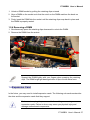
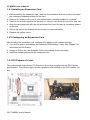
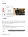
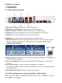
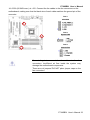
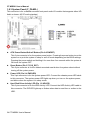
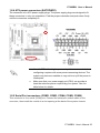
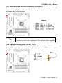
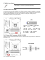
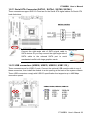
C&T Solution Inc. 12F.-1,No700,Zhongzheng Rd.,Zhonghe Dist., New Taipei City 235,Taiwan(R.O.C) TEL:02-7731-7888 ; FAX:02-7731-7855 CT-MSB01 Intel® Q67 with Core™ i7/ i5 /i3 Micro-ATX Motherboard User’s Manual Ver. 0.9 30GS0900009A09 CT-MSB01 User’s Manual Contents Safety Information ................................................................................................................ 4 About this guide.................................................................................................................... 5 Typography ........................................................................................................................... 6 Packing List ........................................................................................................................... 7 Revision History.................................................................................................................... 8 Specifications Summary ...................................................................................................... 9 Block Diagram ..................................................................................................................... 10 Chapter 1 - Product Introduction ....................................................................................... 11 Chapter 1 - Product Introduction ....................................................................................... 12 1.1 Product highlights ....................................................................................................... 12 1.2 Before you Proceed ................................................................................................... 14 1.3 Motherboard Overview ............................................................................................... 15 1.3.2 Screw Holes ........................................................................................................................................... 15 1.3.3 Motherboard Layout ............................................................................................................................... 16 1.3.4 Layout Content List ................................................................................................................................ 16 1.3.5 Internal Connector.................................................................................................................................. 17 1.4 Central Processing Unit (CPU)................................................................................... 18 1.4.1 Installing the CPU .................................................................................................................................. 18 1.4.2 Installing the CPU Heatsink and Fan ..................................................................................................... 20 1.5 System Memory ......................................................................................................... 24 1.5.1 Overview ................................................................................................................................................ 24 1.5.2 Memory Configurations .......................................................................................................................... 25 1.5.3 Installing a DIMM ................................................................................................................................... 25 1.5.4 Removing a DIMM ................................................................................................................................. 27 1.6 Expansion Card.......................................................................................................... 27 1.6.1 Installing an Expansion Card ................................................................................................................. 28 1.6.2 Configuring an Expansion Card ............................................................................................................. 28 1.6.3 PCI Express x16 slot .............................................................................................................................. 28 1.6.4 PCI Express x 4 slot ............................................................................................................................... 29 1.6.5 PCI Express x 1 slot ............................................................................................................................... 29 1.6.6 PCI slot ................................................................................................................................................... 30 1.7 Jumpers ..................................................................................................................... 30 1.7.1 Clear CMOS (CMOS1)........................................................................................................................... 30 1.7.2 AT/ATX Power Mode Select (PSON1)................................................................................................... 31 1.8 Connectors ................................................................................................................. 32 1.8.1 Rear panel connectors ........................................................................................................................... 32 1.8.2 CPU and System fan connectors (FAN 1, FAN2, FAN 3)...................................................................... 32 2 CT-MSB01 User’s Manual CT-MSB01 User’s Manual 1.8.3 System Panel (F_PANEL) ...................................................................................................................... 34 1.8.4 ATX power connectors (EATXPWR1) .................................................................................................... 35 1.8.5 Serial Port connectors (COM2, COM3, COM4, COM5, COM6) ............................................................ 35 1.8.6 Digital IO Connector (JDIO1) ................................................................................................................. 36 1.8.7 Audio Mic.-In & Line-Out Connector (FPAAUD1) .................................................................................. 37 1.8.8 Digital Audio connector (SPDIF_OUT)................................................................................................... 37 1.8.9 SPI Connector (CN4) ............................................................................................................................. 38 1.8.10 Serial ATA Connector (SATA1, SATA2) .............................................................................................. 38 1.8.11 Serial ATA Connector (SATA3 , SATA4 , SATA5, SATA6 ) ................................................................ 39 1.8.12 USB connectors (USB56, USB78, USB910, USB1112,) ..................................................................... 39 Chapter 2 - BIOS Setup ...................................................................................................... 42 2.1 BIOS Setup Program ................................................................................................. 42 2.1.1 Legend Box ............................................................................................................................................ 43 2.1.2 List Box ................................................................................................................................................... 43 2.1.3 Sub-menu ............................................................................................................................................... 43 2.2 2.3 2.4 BIOS Menu Screen .................................................................................................... 44 Main Setup ................................................................................................................. 45 Advanced BIOS Setup ............................................................................................... 46 2.4.1 PCI Subsystem Setting .......................................................................................................................... 46 2.4.2 ACPI Settings ......................................................................................................................................... 49 2.4.3 Trusted computing.................................................................................................................................. 50 TPM configuration ........................................................................................................................................... 50 2.4.4 CPU configuration .................................................................................................................................. 51 2.4.5 SATA Configuration................................................................................................................................ 53 2.4.6 Intel IGO SWSCI OpRegion ................................................................................................................... 54 2.4.7 Intel TXT(LT) Configuration .................................................................................................................... 55 2.4.8 USB Configuration.................................................................................................................................. 56 2.4.9 AMT Configuration ................................................................................................................................. 57 2.4.10 Super IO Configuration......................................................................................................................... 58 2.4.11 Hardware Monitor ................................................................................................................................. 68 2.4.12 Serial Port Console Redirection ........................................................................................................... 69 2.5 Chipset ....................................................................................................................... 71 2.5.1 North Bridge ........................................................................................................................................... 72 2.5.2 South Bridge ........................................................................................................................................... 73 2.5.3 ME Subsystem ....................................................................................................................................... 78 2.6 2.7 2.8 Boot............................................................................................................................ 79 Security ...................................................................................................................... 81 Save & Exit ................................................................................................................ 82 CT-MSB01 User’s Manual 3 CT-MSB01 User’s Manual Safety Information Electrical safety To prevent electrical shock hazard, disconnect the power cable from the electrical outlet before relocating the system. When adding or removing devices to or from the system, ensure that the power cables for the devices are unplugged before the signal cables are connected. If possible, disconnect all power cables from the existing system before you add a device. Before connecting or removing signal cables from the motherboard, ensure that all power cables are unplugged. Seek professional assistance before using an adapter or extension cord. These devices could interrupt the grounding circuit. Make sure that your power supply is set to the correct voltage in your area. If you are not sure about the voltage of the electrical outlet you are using, contact your local power company. If the power supply is broken, do not try to fix it by yourself. Contact a qualified service technician or your retailer. Operation safety Before installing the motherboard and adding devices on it, carefully read all the manuals that came with the package. Before using the product, make sure all cables are correctly connected and the power cables are not damaged. If you detect any damage, contact your dealer immediately. To avoid short circuits, keep paper clips, screws, and staples away from connectors, slots, sockets and circuitry. Avoid dust, humidity, and temperature extremes. Do not place the product in any area where it may become wet. Place the product on a stable surface. If you encounter technical problems with the product, contact a qualified service technician or your retailer. The symbol of the crossed out wheeled bin indicates that the product (electrical and electronic equipment) should not be placed in municipal waste. Check local regulations for disposal of electronic products. 4 CT-MSB01 User’s Manual CT-MSB01 User’s Manual Safety Declaration This device complies with the requirements in Part 15 of the FCC rules. Operation is subject to the following two conditions: This device may not cause harmful interference. This device must accept any interference received, including interference that may cause undesired operation. About this guide This user guide contains the information you need when installing and configuring the motherboard. How this guide is organized This manual contains the following parts: Chapter 1: Product introduction This chapter describes the features of the motherboard and the new technology it supports. This chapter also lists the hardware setup procedures that you have to perform when installing system components. It includes description of the jumpers and connectors on the motherboard. Chapter 2: BIOS setup This chapter tells how to change system settings through the BIOS Setup menus. Detailed descriptions of the BIOS parameters are also provided. Where to find more information Refer to the following sources for additional information and for product and software updates. 1. Technical Support If a problem arises with your system and no solution can be obtained from the user’s manual, please contact your place of purchase or local distributor. 2. Optional documentation Your product package may include optional documentation, such as warranty flyers, that may have been added by your dealer. These documents are not part of the standard package. CT-MSB01 User’s Manual 5 CT-MSB01 User’s Manual Conventions used in this guide To make sure that you perform certain tasks properly, take note of the following symbols used throughout this manual. DANGER/WARNING: Information to prevent injury to yourself when trying to complete a task. CAUTION: Information to prevent damage to the components when trying to complete a task. IMPORTANT: Instructions that you MUST follow to complete a task. NOTE: Tips and additional information to help you complete a task. Typography Bold text Italics <Key> Indicates a menu or an item to select Used to emphasize a word or a phrase Keys enclosed in the less-than and greater-than sign means that you must press the enclosed key Example: <Enter> means that you must press the Enter or Return key <Key1>+<Key2>+<Key3> If you must press two or more keys simultaneously, the key names are linked with a plus sign (+) Example: <Ctrl>+<Alt>+<D> Means that you must type the command exactly as shown, Command then supply the required item or value enclosed in brackets Example: At the DOS prompt, type the command line: afudos /i[filename] afudos /iP5P800VM.ROM 6 CT-MSB01 User’s Manual CT-MSB01 User’s Manual Packing List Before you begin installing your single board, please make sure that the following materials have been shipped: 1 x CT-MSB01 Micro-ATX Main board 1 x CD-ROM contains OS drivers 1 x COM cable 2 x SATA cable 1 x I/O Shield 1 x Startup Manual If any of the above items is damaged or missing, please contact your retailer. CT-MSB01 User’s Manual 7 CT-MSB01 User’s Manual Revision History Revision V 1.0 Revision History First release version for PCB R11 8 CT-MSB01 User’s Manual Date December , 2010 CT-MSB01 User’s Manual Specifications Summary Specifications System CPU Intel LGA1155 socket supports Intel Core i7/ i5/ i3 CPU BIOS AMI 16Mb SPI System Chipset Intel® Q67 I/O Chipset Nuvoton NCT6776F Memory Four 240-pin UDIMM sockets support up to 16GB dual channel DDR3 1066/ 1333 SDRAM Watchdog Timer Reset: 1 to 255 sec/min per step H/W Status Monitor Monitoring temperature, voltage and cooling fan status. Auto throttling control when CPU overheats. Expansion Slots 1 PCI-E x 16, 1 PCI-E x 4, 1 PCI-E x 1, 1 PCI Power State S1, S3, S4, S5 Wake up on LAN or Ring LAN (WOL) and Ring (WO) Smart Fan Control Yes Smart Fan Control Supports 3 modes (Silent/Optimal/Performance) Display Chipset Intel® GMA HD 2000/ 3000 supports DirectX 10.1, OpenGL 3.0 Display Memory Shared Memory, up to 1GB Dual Display VGA + DisplayPort, VGA + HDMI, HDMI + DisplayPort VGA Onboard, supports max resolution 2048 x 1536 (@60Hz) HDMI Onboard HDMI 1.3, supports max resolution 1920 x 1080 (@60Hz) DisplayPort Onboard, supports max resolution 1920 x 1080 (@60Hz) Audio Audio Codec Realtek ALC892, 5.1 Channel HD Audio Audio Interface Line-in, Line-out, Mic-in, S/PDIF, Front Audio Header Ethernet LAN1 Intel 82579LM LAN2 Intel 82583V * Specifications are subject to change without notice. CT-MSB01 User’s Manual 9 CT-MSB01 User’s Manual Block Diagram 10 CT-MSB01 User’s Manual CT-MSB01 User’s Manual This chapter describes the motherboard features and the new technologies it supports. 1 Product Introduction CT-MSB01 User’s Manual 11 CT-MSB01 User’s Manual Chapter 1 - Product Introduction 1.1 Product highlights 1.1.1 Product Overview Supports latest Intel LGA 1155 CPU-socket interface processor, the 2nd Generation Intel® Core i3, i5, i7 desktop processors which are built on 32 nm technologies to provide smart performance and responsiveness on executing tasks, It combines the CPU and GPU to offer fantastic HD media and graphics, especially on 3D gaming experience. Doubles the bandwidth of your system memory up to 21GB/s and pumps up the system performance at lower power. DMI (Direct Media Interface) architecture connects between the processor and chipset at 5.0GT/s which twice the speed of previous version. The exceptionally increased interconnect bit rate from 2.5GT/s up to 5.0GT/s would effectively eliminates the bottle neck of the system performance and brings the most terrific computing experience from the present to the future. Doubles the transfer speed of SATA 3G, running at speed up to 6.0 Gb/s, and can connect with any other SATA 3.0Gb/s and 1.5Gb/s devices for backward compatibility. Supports RAID 0(Striped disk array), RAID 1(Mirroring disk array), RAID 5(Block Interleaved Distributed Parity), RAID 10 (A Stripe of Mirrors). Provides users the performance and protection. Integrated 5.1-channel HD Audio CODEC delivering advanced multi-channel audio and bringing you the experience of home theater-quality sound. Delivers transfer speed ten times faster than conventional 10/ 100 Ethernet connections, supporting a high transfer rate up to Gigabit/s. Gigabit LAN is the networking standards for the future and is ideal for handing large amount of data such as video, audio, and voice. Choose an environment-friendly, fully RoHS-compliant ECS product as the foundation for keeping harmful substances out of our ecosystem. 1.1.2 Platform Features and Benefits •Integrated Gfx (Intel® HD Graphics 3000/2000) with enhanced operating modes to enable excellent graphics performance in power and cost sensitive embedded applications • DirectX® 10.1 & Open GL 3.0 let you enjoy awesome graphics performance, stunning 3D visual effect and dynamic interactivity • Memory support, integrated low voltage DDR3 memory controller • Operating system support: - Microsoft 12 CT-MSB01 User’s Manual CT-MSB01 User’s Manual -WindRiver -Redhat -Novell -Green Hills -QNX - LinuxWorks 1.1.3 Key Architecture Features • Supports Intel LGA 1155 CPU, the 2nd Generation Intel® Core i3, i5, i7 desktop processors. -32nm monolithic die -Integrated Gfx (Intel® HD Graphics 3000/2000) & memory controller -4 &2 Cores, up to 6MB LLC -HW accelerated video CODECs - Compatible with high speed DDR3-1333 -PCIe* (CPU): Gen 2.0, 5GT/s, up to 20 lanes (4 ctls)** -TDP: 17W-45W (Low Power), 65W-95W (Scalable) • Intel® Turbo Boost Technology -More efficient power sharing between CPU and Graphics • Intel® Hyper-Threading Technology • Intel® Advanced Vector Extensions (Intel® AVX) • Intel® AES-New Instructions • Integrated Display Interfaces - Dual Independent Display Support - HDMI - DisplayPort - Analog VGA • Intel® HD Graphics 3000/2000 - DirectX® 10.1 - Improved realism for DX 3D applications. Improved rendering. - OpenGL 3.0 - Improved realism for OGL 3D based application - UVD (Unified Video Decoder) 2.01 Hardware decode of most common HD codecs (MPEG-2, H.264/AVC MPEG-4 and VC-1) - Supports ATI Hybrid CrossFireXTM Technology2 • Intel Quick Sync Video - Enables faster and higher quality video editing, recording and sharing • I/O - PCI Express® x 16 Gen 2 5GT/s - PCI Express® x 4Gen 2 5GT/s CT-MSB01 User’s Manual 13 CT-MSB01 User’s Manual - PCI Express® x 1Gen 2 5GT/s - PCI 2.3 interface - Six SATA ports (2 port of Gen 2.0 and 4 ports of Gen 3.0) support RAID 0,1, 5, 10 - Gigabit Ethernet Media Access Controller (GbE MAC) IPv4 and IPv6 Checksum Offload - High Definition Audio - USB: Gen 2.0, up to 14 ports - SMBus 2.0 - LPC Bus Supports SPI devices - Hardware Monitor Fan control (Voltage, Temp) Watchdog timer • Power Management - Dual Dynamic Power Management Separate power planes for cores and memory controller - Advanced Configuration and Power Interface (ACPI) 3.0 - AMD PowerNow! and AMD Cool’n’Quiet technologies support 1.2 Before you Proceed Take note of the following precautions before you install motherboard components or change any motherboard settings. Unplug the power cord from the wall socket before touching any component. Use a grounded wrist strap or touch a safely grounded object or a metal object, such as the power supply case, before handling components to avoid damaging them due to static electricity Hold components by the edges to avoid touching the ICs on them. Whenever you uninstall any component, place it on a grounded anti-static pad or in the bag that came with the component. Before you install or remove any component, ensure that the ATX power supply is switched off or the power cord is detached from the power supply. Failure to do so may cause severe damage to the motherboard, peripherals, and/or components. 14 CT-MSB01 User’s Manual CT-MSB01 User’s Manual 1.3 Motherboard Overview Before you install the motherboard, study the configuration of your chassis to ensure that the motherboard fits into it. Refer to the chassis documentation before installing the motherboard. Make sure to unplug the power cord before installing or removing the motherboard. Failure to do so can cause you physical injury and damage motherboard components. 1.3.1 Placement Direction When installing the motherboard, make sure that you place it into the chassis in the correct orientation. The edge with external ports goes to the rear part of the chassis as indicated in the image below. 1.3.2 Screw Holes Place eight (8) screws into the holes indicated by circles to secure the motherboard to the chassis. Do not over tighten the screws! Doing so can damage the motherboard. Place this side towards the rear of the chassis. CT-MSB01 User’s Manual 15 CT-MSB01 User’s Manual 1.3.3 Motherboard Layout 1.3.4 Layout Content List Slots & socket Label Function Note Page LGA1155 LGA1155 socket DIMMA1 240-pin DDR3 DIMM Slot A1 23 DIMMA2 240-pin DDR3 DIMM Slot A2 23 DIMMB1 240-pin DDR3 DIMM Slot B1 23 DIMMB2 240-pin DDR3 DIMM Slot B2 23 PCIEX16 PCI-e x16 Slot 26 PCIEX4 PCI-e x4 Slot 26 PCIEX1 PCI-e x1 Slot 26 16 CT-MSB01 User’s Manual CT-MSB01 User’s Manual Jumpers Label Function Note Page JCMOS1 Clear CMOS 3 x 1 header, pitch 2.54mm 27 PSON1 AT/ATX Mode Select 3 x 1 header, pitch 2.54mm 28 Note Page Rear Panel Connector Label Function KBMS PS/2 Keyboard and Mouse 6-pin Mini-Din 29 COM1 COM1 Connector D-sub 9-pin, male 29 DP1 DisplayPort Connector DisplayPort VGA1 VGA Port D-sub 15-pin, female 29 HDMI1 HDMI Port HDMI 1.3 19-pin 29 LAN1USB12 RJ-45 Ethernet Connector x 1 USB 2.0 Connector x 2 LAN2USB34 RJ-45 Ethernet Connector x 1 USB 2.0 Connector x 2 Audio1 Audio Line-In , Line-Out , Mic.-In 29 5.1 Channel Audio I/O (3 jacks) 29 1.3.5 Internal Connector Internal Connector Label Function Note Page FAN1 CPU Fan Connector 4 x 1 wafer, pitch 2.54mm 30 FAN2 System Fan Connector 3 x 1 wafer, pitch 2.54mm 30 FAN3 Chassis Fan Connector 3 x 1 wafer, pitch 2.54mm 30 COM2 ~ 6 Serial Port Connector * 5 5 x 2 header, pitch 2.54mm JDIO1 Digital I/O Connector 6 x 2 header, pitch 2.54mm 30 F_PANEL Intel Front Panel connector 5 x 2 header, pitch 2.54mm 31 EATXPWR1 ATX power connectors 10 x 2 header 32 KBMS2 PS2 Keyboard & mouse connector 5 x 2 header, pitch 2.54mm 33 FPAUD1 Audio Mic.-In & Line-Out Connector 5 x 2 header, pitch 2.54mm 35 SPDIF_OUT1 Digital Audio connector 4 x 1 header, pitch 2.54mm 35 TPM TPM Connector 10 x 2 header, pitch 2.54mm CN4 SPI Connector 4 x 2 header, pitch 2.54mm 36 SATA1 ~ 6 SATA Data Connector * 6 7P Male connector 36 USB56 USB78 USB Connector * 8 5 x 2 header, pitch 2.54mm 37 CT-MSB01 User’s Manual 17 CT-MSB01 User’s Manual USB910 USB1112 1.4 Central Processing Unit (CPU) The motherboard comes with a surface mount LGA1155 socket designed for the Intel® Core™ i7/ i5/ i3 processor in the 1155-land package. Your boxed Intel® Core™ i7/ i5/ i3 LGA1155 processor package should come with installation instructions for the CPU, fan and heatsink assembly. If the instructions in this section do not match the CPU documentation, follow the latter. Upon purchase of the motherboard, make sure that the PnP cap is on the socket and the socket pins are not bent. Contact your retailer immediately if the PnP cap is missing, or if you see any damage to the PnP cap/socket pins/motherboard components. The product warranty does not cover damage to the socket pins resulting from incorrect CPU installation/removal, or misplacement/loss/incorrect removal of the PnP cap. Install the CPU fan and heatsink assembly before you install motherboard to the chassis. If you purchased a separate CPU heatsink and fan assembly, make sure that you have properly applied Thermal Interface Material to the CPU heatsink or CPU before you install the heatsink and fan assembly. 1.4.1 Installing the CPU 1. Locate the CPU socket on the motherboard. 18 CT-MSB01 User’s Manual CT-MSB01 User’s Manual Before installing the CPU, make sure that the socket box is facing towards you and the load lever is on your left. 2. Press the load lever with your thumb (A), then move it to the left (B) until it is released from the retention tab. Retention tab A Load lever B To prevent damage to the socket pins, do not remove the PnP cap unless you are installing a CPU. 3. Lift the Load lever with your thumb and forefinger to around 180º angle (A), then pull the PnP cap from the CPU socket to remove (B). CT-MSB01 User’s Manual 19 CT-MSB01 User’s Manual B A 4. Position the CPU over the socket, making sure that the gold triangle is on the top-left corner of the socket then fit the socket alignment key into the CPU notch. Gold triangle CPU notch Alignment key 5. Pull back the load lever , then push the load lever (A) until it snaps into the retention tab. A The CPU fits in only one correct orientation. DO NOT force the CPU into the socket to prevent bending the connectors on the socket and damaging the CPU! 1.4.2 Installing the CPU Heatsink and Fan Intel® Core™ i7/ i5/ i3 LGA1155 processor requires a specially designed heatsink and fan 20 CT-MSB01 User’s Manual CT-MSB01 User’s Manual assembly to ensure optimum thermal condition and performance. Install the motherboard to the chassis before you install the CPU fan and heatsink assembly. When you buy a boxed Intel® Core™ i7/ i5/ i3 LGA1155 processor, the package includes the CPU fan and heatsink assembly. If you buy a CPU separately, make sure that you use only Intel® certified multi‑directional heatsink and fan. Your Intel® Core™ i7/ i5/ i3 LGA1155 processor LGA1155 heatsink and fan assembly comes in a push-pin design and requires no tool to install. If you purchased a separate CPU heatsink and fan assembly, make sure that you have properly applied Thermal Interface Material to the CPU heatsink or CPU before you install the heatsink and fan assembly. To install the CPU heatsink and fan: 1. Place the heatsink on top of the installed CPU, making sure that the four fasteners match the holes on the motherboard. Narrow end of the groove Fastener Motherboard hole Orient the heatsink and fan assembly such that the CPU fan cable is closest to the CPU fan connector. Make sure each fastener is oriented as shown, with the narrow groove directed outward. CT-MSB01 User’s Manual 21 CT-MSB01 User’s Manual 2. Push down two fasteners at a time in a diagonal sequence to secure the heatsink and fan assembly in place. A B B A A B B A 3. Connect the CPU fan cable to the connector on the motherboard labeled CPU_FAN. FAN 1 CPU FAN Do not forget to connect the fan cables to the fan connectors. Insufficient air flow inside the system may damage the motherboard components. These are not jumpers! DO NOT place jumper caps on the fan connectors. 1.4.3 Uninstalling the CPU Heatsink and Fan To uninstall the CPU heatsink and fan: 1. Disconnect the CPU fan cable from the connector on the motherboard. 2. Rotate each fastener counterclockwise 22 CT-MSB01 User’s Manual CT-MSB01 User’s Manual 3. Pull up two fasteners at a time in a diagonal sequence to disengage the heatsink and fan assembly from the motherboard. A A B B B A B A 4. Carefully remove the heatsink and fan assembly from the motherboard. CT-MSB01 User’s Manual 23 CT-MSB01 User’s Manual 5. Rotate each fastener clockwise to ensure correct orientation when reinstalling. 1.5 System Memory 1.5.1 Overview The motherboard comes with four 240-pin Double Data Rate 3 (DDR3) Dual Inline Memory Modules (DIMM) sockets. A DDR3 module has the same physical dimensions as a DDR DIMM but has a 240-pin footprint compared to the 240-pin DDR2 DIMM. DDR3 DIMMs are notched differently to prevent installation on a DDR2 DIMM socket. The following figure illustrates the location of the sockets: 240-Pin DDR3 DIMM sockets 24 CT-MSB01 User’s Manual CT-MSB01 User’s Manual Channel Channel A Channel B Socket DIMMA1 DIMMA2 DIMMB1 DIMMB2 1.5.2 Memory Configurations You may install 1 GB, 2 GB , and 4 GB unbuffered ECC or non-ECC DDR3 DIMMs into the DIMM sockets using the memory configurations in this section. IF you installed four 1GB memory modules, the system may detect less than 3GB of total memory because of address space allocation for other critical functions. This limitation applies to Windows XP 32-bit version operating system since it does not support PAE (Physical Address Extension) mode. IF you install Windows XP 32-bit version operating system, we recommend that you install less than 3GB of total memory. For dual-channel configuration, the total size of memory module(s) installed per channel must be the same for better performance (DIMMA1 +DIMMA2=DIMMB1+DIMMB2). When using one DDR3 DIMM module, install into DIMMB1 slot only. When using two DDR3 DIMM modules, install into DIMMA1 and DIMMB1 slots only. Always install DIMMs with the same CAS latency. For optimum compatibility, it is recommended that you obtain memory modules from the same vendor. Refer to the memory Qualified Vendors List on the next page for details. Due to CPU limitation, DIMM modules with 128 Mb memory chips or double-sided x16 memory chips are not supported in this motherboard. 1.5.3 Installing a DIMM 1. 2. Unlock a DIMM socket by pressing the retaining clips outward. Align a DIMM on the socket such that the notch on the DIMM matches the break on the socket. CT-MSB01 User’s Manual 25 CT-MSB01 User’s Manual DDR3 DIMM notch Unlocked retaining clip 3. Firmly insert the DIMM into the socket until the retaining clips snap back in place and the DIMM is properly seated. Locked retaining clip A DDR3 DIMM is keyed with a notch so that it fits in only one direction. DO NOT force a DIMM into a socket to avoid damaging the DIMM. The DDR3 DIMM sockets do not support DDR DIMMs. DO NOT install DDR2 DIMMs to the DDR3 DIMM socket. Make sure to unplug the power supply before adding or removing DIMMs or other system components. Failure to do so may cause severe damage to both the motherboard and the components. 26 CT-MSB01 User’s Manual CT-MSB01 User’s Manual 1. Unlock a DIMM socket by pulling the retaining clips outward 2. Align a DIMM on the socket such that the notch on the DIMM matches the break on the socket. 3. Firmly insert the DIMM into the socket until the retaining clips snap back in place and the DIMM is properly seated. 1.5.4 Removing a DIMM 1. Simultaneously press the retaining clips downward to unlock the DIMM. 2. Remove the DIMM from the socket. Unlocked retaining clip Support the DIMM lightly with your fingers when pressing the retaining clips. The DIMM might get damaged when it flips out with extra force. 1.6 Expansion Card In the future, you may need to install expansion cards. The following sub-sections describe the slots and the expansion cards that they support. Make sure to unplug the power cord before adding or removing expansion cards. Failure to do so may cause you physical injury and damage motherboard components. CT-MSB01 User’s Manual 27 CT-MSB01 User’s Manual 1.6.1 Installing an Expansion Card 1. Before installing the expansion card, read the documentation that came with it and make the necessary hardware settings for the card. 2. Remove the system unit cover (if your motherboard is already installed in a chassis). 3. Remove the bracket opposite the slot that you intend to use. Keep the screw for later use. 4. Align the card connector with the slot and press firmly until the card is completely seated on the slot. 5. Secure the card to the chassis with the screw you removed earlier. 6. Replace the system cover. 1.6.2 Configuring an Expansion Card After installing the expansion card, configure it by adjusting the software settings. 1. Turn on the system and change the necessary BIOS settings, if any. See Chapter 2 for information on BIOS setup. 2. Assign an IRQ to the card if needed. Refer to the tables on the next page. 3. Install the software drivers for the expansion card. 1.6.3 PCI Express x16 slot This motherboard supports one PCI Express x16 slot that complies with the PCI Express specifications. The following figure shows a graphics card installed on the PCI Express x16 slot. 28 CT-MSB01 User’s Manual CT-MSB01 User’s Manual 1.6.4 PCI Express x 4 slot This motherboard supports one PCI Express x4 slot that complies with the PCI Express specifications. The following figure shows a RAID card installed on the PCI Express x 4 slot. 1.6.5 PCI Express x 1 slot This motherboard supports one PCI Express x 1 slot that complies with the PCI Express specifications. The following figure shows a LAN card installed on the PCI Express x 1 slot. CT-MSB01 User’s Manual 29 CT-MSB01 User’s Manual 1.6.6 PCI slot This motherboard supports one PCI slot that complies with the PCI specifications. The following figure shows a audio card installed on the PCI slot. 1.7 Jumpers 1.7.1 Clear CMOS (CMOS1) This jumper allows you to clear the Real Time Clock (RTC) RAM in CMOS. You can clear the CMOS memory of date, time, and system setup parameters by erasing the CMOS RTC RAM data. The onboard button cell battery powers the RAM data in CMOS, which includes system setup information such as system passwords. To erase the RTC RAM: 1. Turn OFF the computer and unplug the power cord. 2. Remove the onboard battery. 3. Move the jumper cap from pins 1-2 (default) to pins 2-3. Keep the cap on pins 2-3 for about 5~10 seconds, then move the cap back to pins 1-2. 4. Re-install the battery. 5. Plug the power cord and turn ON the computer. 6. Hold down the <Del> key during the boot process and enter BIOS setup to re-enter data. Except when clearing the RTC RAM, never remove the cap on CLRTC jumper default position. Removing the cap will cause system boot failure! 30 CT-MSB01 User’s Manual CT-MSB01 User’s Manual Normal (Default) Clear CMOS You do not need to clear the RTC when the system hangs due to overclocking. For system failure due to overclocking, use the C.P.R. (CPU Parameter Recall) feature. Shut down and reboot the system so the BIOS can automatically reset parameter settings to default values. 1.7.2 AT/ATX Power Mode Select (PSON1) This jumper allows you to select ATX Mode or AT mode . ATX MODE (Default) AT MODE CT-MSB01 User’s Manual 31 CT-MSB01 User’s Manual 1.8 Connectors 1.8.1 Rear panel connectors 1. PS/2 mouse port (green). This port is for a PS/2 mouse. 2. PS/2 keyboard port (purple). This port is for a PS/2 keyboard. 3. Serial connector. This 9-pin COM1 & COM2 port is for serial devices. 4. DisplayPort. This 20-pin DisplayPort connect to a DisplayPort VGA monitor. 5. VGA port. This 15-pin VGA port connects to a VGA monitor. 6. HDMI port. This 19-pin HDMI 1.3 port connects to a HDMI monitor. 7. LAN (RJ-45) port. This port allows Gigabit connection to a Local Area Network (LAN) through a network hub. Refer to the table below for the LAN port LED indications. LAN port LED indications SPEED LED Status Description ACT / LINK LED Status Description OFF 10Mbps connection OFF No link Orange 100Mbps connection Green Link Green 1Gbps connection Blinking Data activity 8. USB 2.0 ports 1 ~ 4. These four 4-pin Universal Serial Bus (USB) ports are available for connecting USB 2.0 devices. 9. Line In port (light blue). This port connects a tape, CD, DVD player, or other audio sources. 10 Line Out port (lime). This port connects a headphone or a speaker. In 4-channel, 6-channel, and 8-channel configuration, the function of this port becomes Front Speaker Out. 11. Microphone port (pink). This port connects a microphone. 1.8.2 CPU and System fan connectors (FAN 1, FAN2, FAN 3) The fan connectors support cooling fans of 280mA (3.36 W max.) at 4800rpm or a total of 32 CT-MSB01 User’s Manual CT-MSB01 User’s Manual 1A~2.22A (26.64W max.) at +12V. Connect the fan cables to the fan connectors on the motherboard, making sure that the black wire of each cable matches the ground pin of the connector. FAN 1 CPU FAN FAN 2 System FAN FAN 3 Chassis Fan Do not forget to connect the fan cables to the fan connectors. Insufficient air flow inside the system may damage the motherboard components. These are not jumpers! DO NOT place jumper caps on the fan connectors. CT-MSB01 User’s Manual 33 CT-MSB01 User’s Manual 1.8.3 System Panel (F_PANEL) This connector is for a chassis-mounted front panel audio I/O module that supports either HD Audio or legacy AC’97 audio standard. F_PANEL ATX Power Button/Soft-off Button (Pin 6-8 PWRBT) This 2-pin connector is for the system power button. Pressing the power button turns the system on or puts the system in sleep or soft-off mode depending on the BIOS settings. Pressing the power switch and holding it for more than four seconds while the system is ON turns the system OFF. Reset Button (Pin 5-7 SYS_RST) This 2-pin connector is for the chassis-mounted reset button for system reboot without turning off the system power. Power LED (Pin 2-4 PWRLED) This 2-pin connector is for the system power LED. Connect the chassis power LED cable to this connector. The system power LED lights up when you turn on the system power, and blinks when the system is in sleep mode. Hard Disk Drive Activity LED (Pin 1-3 HDLED) This 2-pin connector is for the HDD Activity LED. Connect the HDD Activity LED cable to this connector. The IDE LED lights up or flashes when data is read from or written to the HDD. 34 CT-MSB01 User’s Manual CT-MSB01 User’s Manual 1.8.4 ATX power connectors (EATXPWR1) The connector is for ATX power supply plugs. The power supply plugs are designed to fit these connectors in only one orientation. Find the proper orientation and push down firmly until the connectors completely fit. EATXPWR1 ATX12V1 Use of a PSU with a higher power output is recommended when configuring a system with more power-consuming devices. The system may become unstable or may not boot up if the power is inadequate. Make sure that your power supply unit (PSU) can provide at least the minimum power required by your system. See the table below for details. 1.8.5 Serial Port connectors (COM2, COM3, COM4, COM5, COM6) This connector is for a serial (COM) port. Connect the serial port module cable to this connector, then install the module to a slot opening at the back of the system chassis. CT-MSB01 User’s Manual 35 CT-MSB01 User’s Manual COM2 , COM3 , COM4 , COM5 , COM6 1.8.6 Digital IO Connector (JDIO1) This connector is for 8-bit General purpose I/O function. JDIO1 36 CT-MSB01 User’s Manual CT-MSB01 User’s Manual 1.8.7 Audio Mic.-In & Line-Out Connector (FPAAUD1) This connector is for a chassis-mounted front panel audio I/O module that supports either HD Audio or legacy AC ‘97 (optional) audio standard. Connect one end of the front panel audio I/O module cable to this connector. FPAAUD1 For motherboards with the optional HD Audio feature, we recommend that you connect a high-definition front panel audio module to this connector to avail of the motherboard’s high‑definition audio capability. 1.8.8 Digital Audio connector (SPDIF_OUT) This connector is for the S/PDIF audio module to allow digital sound output. Connect one end of the S/PDIF audio cable to this connector and the other end to the S/PDIF module. SPDIF_OUT CT-MSB01 User’s Manual 37 CT-MSB01 User’s Manual The S/PDIF out module is purchased separately. 1.8.9 SPI Connector (CN4) Is a point-to-point interface standard, which allows network equipment designers to develop an array of next-generation multi-service switches and routers to support multi-service traffic with aggregate bandwidths up to OC-192 (10 Gb/s) and beyond, enabling them to dramatically increase system performance. TPM 1.8.10 Serial ATA Connector (SATA1, SATA2) These connectors support SATA 3.0 and are for the Serial ATA signal cables for Serial ATA hard disk drives. SATA1、SATA2 38 CT-MSB01 User’s Manual CT-MSB01 User’s Manual 1.8.11 Serial ATA Connector (SATA3 , SATA4 , SATA5, SATA6 ) These connectors support SATA 2.0 and are for the Serial ATA signal cables for Serial ATA hard disk drives. SATA1、SATA2 Connect the right-angle side of SATA signal cable to SATA device. Or you may connect the right-angle side of SATA cable to the onboard SATA port to avoid mechanical conflict with large graphics cards. 1.8.12 USB connectors (USB56, USB78, USB910, USB1112,) These connectors are for USB 2.0 ports. Connect the optional USB module cable to any of these connectors, then install the module to a slot opening at the back of the system chassis. These USB connectors comply with USB 2.0 specification that supports up to 480 Mbps connection speed. USB56, USB78, USB910, USB1112 CT-MSB01 User’s Manual 39 CT-MSB01 User’s Manual Never connect a 1394 cable to the USB connectors. Doing so will damage the motherboard! The USB module is purchased separately. 40 CT-MSB01 User’s Manual CT-MSB01 User’s Manual This chapter tells how to change the system settings through the BIOS Setup menus. Detailed descriptions of the BIOS parameters are also provided. 2 CT-MSB01 User’s Manual 41 CT-MSB01 User’s Manual Chapter 2 - BIOS Setup 2.1 BIOS Setup Program This motherboard supports a programmable firmware chip that you can update using the provided utility. Use the BIOS Setup program when you are installing a motherboard, reconfiguring your system, or prompted to “Run Setup.” This section explains how to configure your system using this utility. Even if you are not prompted to use the Setup program, you can change the configuration of your computer in the future. For example, you can enable the security password feature or change the power management settings. This requires you to reconfigure your system using the BIOS Setup program so that the computer can recognize these changes and record them in the CMOS RAM of the firmware hub. The firmware hub on the motherboard stores the Setup utility. When you start up the computer, the system provides you with the opportunity to run this program. Press <Del> during the Power-On-Self-Test (POST) to enter the Setup utility; otherwise, POST continues with its test routines. If you wish to enter Setup after POST, restart the system by pressing <Ctrl+Alt+Delete>, or by pressing the reset button on the system chassis. You can also restart by turning the system off and then back on. Do this last option only if the first two failed. The Setup program is designed to make it as easy to use as possible. Being a menu-driven program, it lets you scroll through the various sub-menus and make your selections from the available options using the navigation keys. The default BIOS settings for this motherboard apply for most conditions to ensure optimum performance. If the system becomes unstable after changing any BIOS settings, load the default settings to ensure system compatibility and stability. Select the Load Optimized Defaults from the BIOS menu screen. The BIOS setup screens shown in this section are for reference purposes only, and may not exactly match what you see on your screen. Visit the system builder’s website to download the latest BIOS file for this motherboard 42 CT-MSB01 User’s Manual CT-MSB01 User’s Manual 2.1.1 Legend Box The keys in the legend bar allow you to navigate through the various setup menus Key(s) Function Description ← Select Screen ↑↓ Select Item +- Change Option / Field Enter Go to Sub Screen PGDN Next Page PGUP Previous Page HOME Go to Top of Screen END Go to Bottom of Screen F2/F3 Change Colors F7 Discard Changes F8 N/A F9 Load Optimal Defaults F10 Save and Exit ESC Exit 2.1.2 List Box This box appears only in the opening screen. The box displays an initial list of configurable items in the menu you selected. 2.1.3 Sub-menu Note that a right pointer symbol appears to the left of certain fields. This pointer indicates that you can display a sub-menu from this field. A sub-menu contains additional options for a field parameter. To display a sub-menu, move the highlight to the field and press <Enter>. The sub-menu appears. Use the legend keys to enter values and move from field to field within a sub-menu as you would within a menu. Use the <Esc> key to return to the main menu. Take some time to familiarize yourself with the legend keys and their corresponding functions. Practice navigating through the various menus and submenus. If you accidentally make unwanted changes to any of the fields, press <F9> to load the optimal default values. While moving around through the Setup program, note that explanations appear in the Item Specific Help window located to the right of each menu. This window displays the help text for the currently highlighted field. CT-MSB01 User’s Manual 43 CT-MSB01 User’s Manual 2.2 BIOS Menu Screen When you enter the BIOS, the following screen appears. The BIOS menu screen displays the items that allow you to make changes to the system configuration. To access the menu items, press the up/down/right/left arrow key on the keyboard until the desired item is highlighted, then press [Enter] to open the specific menu. 44 CT-MSB01 User’s Manual CT-MSB01 User’s Manual 2.3 Main Setup This menu gives you an overview of the general system specifications. The BIOS automatically detects the items in this menu. Use this menu for basic system configurations, such as time, date etc. BIOS Information Displays the auto-detected BIOS information. Memory Information Displays the auto-detected system memory System Date The date format is <Date>,<Month>,<Day>,<Year>. System Time The time format is <Hour>,<Minute>,<Second>. Access Level Displays the accessory information. CT-MSB01 User’s Manual 45 CT-MSB01 User’s Manual 2.4 Advanced BIOS Setup Select the Advanced tab from the setup screen to enter the Advanced BIOS Setup screen. You can select any of the items in the left frame of the screen, such as Chipset configuration, to go to the sub menu for that item. You can display an Advanced BIOS Setup option by highlighting it using the <Arrow> keys. All Advanced BIOS Setup options are described in this section. The Advanced BIOS Setup screen is shown below. The sub menus are described on the following pages. Take caution when changing the settings of the Advanced menu items. Incorrect field values can cause the system to malfunction. 2.4.1 PCI Subsystem Setting The PCI PnP menu items allow you to change the advanced settings for PCI/PnP devices. The menu includes setting IRQ and DMA channel resources for either PCI/PnP or legacy ISA devices, and setting the memory size block for legacy ISA devices. 46 CT-MSB01 User’s Manual CT-MSB01 User’s Manual PCI Bus Driver Version Displays the information of PCI Bus Driver Version . PCI ROM Priority [EFI compatible ROM] In case of multiple option ROMs ( Legacy and EFI compatible), specifies what PCI option ROM to launch. PCI Common Settings PCI Latency Timer [32 PCI Bus Clocks] Allows the PCI Latency Timer to be adjusted. This option sets the latency of all PCI devices on the PCI bus. Configuration options: [32 PCI Bus Clocks] [64 PCI Bus Clocks] [96 PCI Bus Clocks] [128 PCI Bus Clocks] [160 PCI Bus Clocks] [192 PCI Bus Clocks] [224 PCI Bus Clocks] [248 PCI Bus Clocks] VGA Palette Snoop [Disable] Enables or disables VGA palette registers snooping. Configuration options: [Disabled] [Enabled] CT-MSB01 User’s Manual 47 CT-MSB01 User’s Manual PERR# Generation [Disable] Enables or disables PCI devices to Generate PERR#. Configuration options: [Disabled] [Enabled] SPERR# Generation [Disable] Enables or disables PCI devices to Generate SPERR#. Configuration options: [Disabled] [Enabled] PCI Express Device Settings Relaxed Ordering [Disable] Enables or disables PCI Express devices Relaxed Ordering Configuration options: [Disabled] [Enabled] Extend Tag If [Enabled] allows device to use 8-bit tag field as a requester. Configuration options: [Disabled] [Enabled] No Snoop [Enabled] Enables or disables PCI Express devices no snoop option. Configuration options: [Disabled] [Enabled] Maximum payload [Auto] Set maximum payload of PCI Express device or allow system BIOS to select the value. Configuration options: [Auto] [128 Bytes] [256 Bytes] [512 Bytes] [1024 Bytes] [2048 Bytes] [4096 Bytes] Maximum Read Request [Auto] Configuration options: [Auto] [128 Bytes] [256 Bytes] [512 Bytes] [1024 Bytes] [2048 Bytes] [4096 Bytes] PCI Express Link Settings ASPM Support [Disable] Set the ASPM levels: Force L0 – Force all links to L0 state; AUTO – BIOS configuration; Disable – Disable ASPM. Configuration options: [Disable][Auto][Force L0] Enabling ASPM may cause some PCI Express devices to fail. Extended Synch [Disables] 48 CT-MSB01 User’s Manual CT-MSB01 User’s Manual If [Enabled] allows generation of extended synchronization patterns. Configuration options: [Disable][Enabled] 2.4.2 ACPI Settings ACPI Sleep State [S3 (suspend to RAM)] Select the highest ACPI sleep state the system will enter the SUSPEND button is press. Configuration options: [Suspend Disable][S1 (CPU Stop Clock)] [S3 (suspend to RAM )] Resume On RTC Alarm [Disable] Enable or disable system wake on alarm even. When enabled, system will wake upon the hr/min/sec specified. Configuration options: [Disabled] [Enabled] CT-MSB01 User’s Manual 49 CT-MSB01 User’s Manual 2.4.3 Trusted computing Trusted computing (TPM) settings. TPM configuration TPM SUPPORT [Disabled] Enable or disable TPM support. Configuration options: [Disabled] [Enabled] Current TPM Status Information Displays the TPM status information [No TPM Hardware] 50 CT-MSB01 User’s Manual CT-MSB01 User’s Manual 2.4.4 CPU configuration CPU configuration Displays the CPU information Hyper-threading [Enabled] Enable or disable Hyper-threading support. Configuration options: [Disabled] [Enabled] Active Processor Cores [All] Select the numbers of cores in each processor package. Configuration options: [All] [1] [2] [3] [4] [5] [6] [7] It depends on each CPU type. Limit CPUID Maximum [Disable] Disable for Windos XP. Configuration options: [Disabled] [Enabled] CT-MSB01 User’s Manual 51 CT-MSB01 User’s Manual Execute Disable Bit [Enable] XD can prevent certain classes of malicious buffer overflow attacks when combined with a supporting OS ( Windows Server 2003 SP1, Windows XP SP2, SuSE Linux 9.2 RedHat Enterprise 3 Update 3.) Configuration options: [Disabled] [Enabled] Hardware Prefetcher [Enable] To turn on/off the Mid Level Cache (L2) streamer Prefetcher Configuration options: [Disabled] [Enabled] Adjacent Chach Line Prefetcher [Enable] To turn on/off prefetching of adjacent chach lines. Configuration options: [Disabled] [Enabled] Intel Virtualization Technology [Disable] When enable, a VMM can utilize the additional hardware capabilities provided by Vanderpool Technology. Configuration options: [Disabled] [Enabled] Power Technology [Energy efficient] Enable the power management features. Configuration options: [Disabled] [Energy efficient] [Enabled] Local x2APIC [Disable] Enable Local x2APIC. Some OSes do not support this. Configuration options: [Disabled] [Enabled] 52 CT-MSB01 User’s Manual CT-MSB01 User’s Manual 2.4.5 SATA Configuration SATA Mode [IDE Mode] Support IDE, AHCI or RAID mode Configuration options: [Disable][IDE Mode][AHCI Mode][RAID Mode] Serial-ATA Controller 0 [Compatible] Enabled/Disabled Serial-ATA Controller 0 Configuration options: [Disable] [Enhanced] [Compatible] Serial-ATA Controller 1 [Enhanced] Enabled/Disabled Serial-ATA Controller 1 Configuration options: [Disable] [Enhanced] [Compatible] CT-MSB01 User’s Manual 53 CT-MSB01 User’s Manual 2.4.6 Intel IGO SWSCI OpRegion Intel IGO SWSCI OpRegion configuration DVMT/FIXED Memory [128MB] Select DVMT/FIXED Mode Memory size used by Internal Graphic Device. Configuration options: [128MB][512MB][Maximum] IGO – Boot Type [VBIOS Default] Select the video Device which will be activated during POST. This has no effect if external graphics present. Configuration options: [VBIOS Default][CRT][HDMI][DisplayPort] 54 CT-MSB01 User’s Manual CT-MSB01 User’s Manual 2.4.7 Intel TXT(LT) Configuration Display Intel Trusted Execution Technology configuration. CT-MSB01 User’s Manual 55 CT-MSB01 User’s Manual 2.4.8 USB Configuration USB Configuration Parameters USB Device Display how many devices are connected. Legacy USB Support [Enabled] Enables Legacy USB support. AUTO option disables legacy support if no USB devices are connected. DISABLE option will keep USB devices available only for EFI applications. Configuration options: [Enabled] [Disabled][Auto] EHCI Hand-off [Disable] This is a workaround for OSes without EHCI hand-off support. The EHCI ownership change should be claimed by EHCI driver. Configuration options: [Disabled] [Enabled] Port 60/64 Emulation [Enabled] Enables I/O port 60h/64h emulation support. This should be enabled for complete USB keyboard legacy support for non-USB aware OSes. 56 CT-MSB01 User’s Manual CT-MSB01 User’s Manual Configuration options: [Disabled] [Enabled] USB hardware delays and time-outs: USB transfer time-out [20 sec] The time-out value for Control, Bulk, and Interrupt transfers. Configuration options: [1 sec] [5 sec] [10 sec] [20 sec] Device reset time-out [20 sec] USB mass storage device Start Unit command time-out. Configuration options: [10 sec] [20 sec] [30 sec] [40 sec] Device Power-up delay [Auto] Maximum time the device will take before it properly reports itself to the Host Controller. ‘Auto’ uses default value: for a Root port it is 100ms, for a Hub port the delay is taken form Hub descriptor. Configuration options: [Auto][Manual] 2.4.9 AMT Configuration AMT Parameters AMT [Enable] CT-MSB01 User’s Manual 57 CT-MSB01 User’s Manual AMT Help Configuration options: [Disabled] [Enabled] Unconfigure AMT/ME [Disable] Perform AMT/ME unconfigure without password operation. Configuration options: [Disabled] [Enabled] WatchDog Timer [Disable] Enable/Disable WatchDog Timer. Configuration options: [Disabled] [Enabled] When ‘Enabled’, OS and BIOS WatchDog Timers can be set. 2.4.10 Super IO Configuration System Super IO Chip Parameters. Super IO Configuration Super IO Chip [NCT6776F] 2.4.10.1 Serial Port 0 configuration 58 CT-MSB01 User’s Manual CT-MSB01 User’s Manual Set Parameters of Serial Port 0 (COMA) Serial Port 0 Configuration Serial Port [Enable] Enable or Disable Serial Port. Configuration options: [Disabled] [Enabled] Device Setting [IO=3F8h; IRQ=4] Change Setting[Auto] Select an optimal setting for Super IO device. Configuration options: [Auto] [IO=3F8h; IRQ=4] [IO=3F8h; IRQ=3, 4, 5, 6, 7, 9. 10, 11, 12] [IO=2F8h; IRQ=3, 4, 5, 6, 7, 9. 10, 11, 12] [IO=3E8h; IRQ=3, 4, 5, 6, 7, 9. 10, 11, 12] [IO=2E8h; IRQ=3, 4, 5, 6, 7, 9. 10, 11, 12] 2.4.10.2 Serial Port 1 configuration Set Parameters of Serial Port 1 (COMA) CT-MSB01 User’s Manual 59 CT-MSB01 User’s Manual Serial Port 1 Configuration Serial Port [Enable] Enable or Disable Serial Port. Configuration options: [Disabled] [Enabled] Device Setting [IO=2F8h; IRQ=3] Change Setting[Auto] Select an optimal setting for Super IO device. Configuration options: [Auto] [IO=2F8h; IRQ=3] [IO=3F8h; IRQ=3, 4, 5, 6, 7, 9. 10, 11, 12] [IO=2F8h; IRQ=3, 4, 5, 6, 7, 9. 10, 11, 12] [IO=3E8h; IRQ=3, 4, 5, 6, 7, 9. 10, 11, 12] [IO=2E8h; IRQ=3, 4, 5, 6, 7, 9. 10, 11, 12] Super IO Chip [Finteck F81216] Serial Port 2 configuration Set Parameters of Serial Port 2 (COMA) 60 CT-MSB01 User’s Manual CT-MSB01 User’s Manual 2.4.10.3 Serial Port 2 Configuration Serial Port [Enable] Enable or Disable Serial Port. Configuration options: [Disabled] [Enabled] Device Setting [IO=C80h; IRQ=5] Change Setting[Auto] Select an optimal setting for Super IO device. Configuration options: [Auto] [IO=C80h; IRQ=5] [IO=C80h; IRQ=5, 7, 9. 10, 11] [IO=C88h; IRQ=5, 7, 9. 10, 11] [IO=C90h; IRQ=5, 7, 9. 10, 11] [IO=C98h; IRQ=5, 7, 9. 10, 11] 2.4.10.4 Serial Port 3 configuration Set Parameters of Serial Port 3 (COMA) CT-MSB01 User’s Manual 61 CT-MSB01 User’s Manual Serial Port 3 Configuration Serial Port [Enable] Enable or Disable Serial Port. Configuration options: [Disabled] [Enabled] Device Setting [IO=C88h; IRQ=5] Change Setting[Auto] Select an optimal setting for Super IO device. Configuration options: [Auto] [IO=C88h; IRQ=5] [IO=C80h; IRQ=5, 7, 9. 10, 11] [IO=C88h; IRQ=5, 7, 9. 10, 11] [IO=C90h; IRQ=5, 7, 9. 10, 11] [IO=C98h; IRQ=5, 7, 9. 10, 11] 2.4.10.5 Serial Port 4 configuration Set Parameters of Serial Port 4 (COMA) 62 CT-MSB01 User’s Manual CT-MSB01 User’s Manual Serial Port 4 Configuration Serial Port [Enable] Enable or Disable Serial Port. Configuration options: [Disabled] [Enabled] Device Setting [IO=C90h; IRQ=5] Change Setting[Auto] Select an optimal setting for Super IO device. Configuration options: [Auto] [IO=C90h; IRQ=5] [IO=C80h; IRQ=5, 7, 9. 10, 11] [IO=C88h; IRQ=5, 7, 9. 10, 11] [IO=C90h; IRQ=5, 7, 9. 10, 11] [IO=C98h; IRQ=5, 7, 9. 10, 11] 2.4.10.6 Serial Port 5 configuration Set Parameters of Serial Port 5 (COMA) CT-MSB01 User’s Manual 63 CT-MSB01 User’s Manual Serial Port 5 Configuration Serial Port [Enable] Enable or Disable Serial Port. Configuration options: [Disabled] [Enabled] Device Setting [IO=C98h; IRQ=5] Change Setting [Auto] Select an optimal setting for Super IO device. Configuration options: [Auto] [IO=C98h; IRQ=5] [IO=C80h; IRQ=5, 7, 9. 10, 11] [IO=C88h; IRQ=5, 7, 9. 10, 11] [IO=C90h; IRQ=5, 7, 9. 10, 11] [IO=C98h; IRQ=5, 7, 9. 10, 11] Smart Fan Function [Enable] Enable or Disable Smart Fan Function Configuration options: [Disabled] [Enabled] 64 CT-MSB01 User’s Manual CT-MSB01 User’s Manual 2.4.10.7 Smart Fan Mode Configruation Smart Fan Mode configuration System Fan Mode [Manual Mode] Select system Fan mode Configuration options: [Manual Mode] [Thermal Cruise Mode][SNART FAN IV Mode] CPU Fan Mode [Manual Mode] Select CPU Fan mode Configuration options: [Manual Mode] [Thermal Cruise Mode][SNART FAN IV Mode] Chassis Fan Mode [Manual Mode] Select Chassis Fan mode Configuration options: [Manual Mode] [Thermal Cruise Mode][SNART FAN IV Mode] Power Failue [Aways on] Enable or Disable Power-Loss Function Configuration options: [Aways OFF] [Aways on][Auto] Resume on PS2 KB [Disabled] CT-MSB01 User’s Manual 65 CT-MSB01 User’s Manual Enable or Disable Resume on PS2 KB Function Configuration options: [Disabled] [Enabled] Resume on PS2 MS[Disabled] Enable or Disable Resume on PS2 MS Function Configuration options: [Disabled] [Enabled] Resume on Ring [Disabled] Enable or Disable Resume on Ring Function Configuration options: [Disabled] [Enabled] Watch Dog Timer [Disabled] Enable or Disable Watch Dog Timer Function Configuration options: [Disabled] [Enabled] 2.4.10.8 Digital I/O Configuration Digital I/O Configuration 66 CT-MSB01 User’s Manual CT-MSB01 User’s Manual Digital I/O Pin 0 [Input] Configure Digital I/O Pin Configuration options: [Input][Output High][Output Low] Digital I/O Pin 1 [Input] Configure Digital I/O Pin Configuration options: [Input][Output High][Output Low] Digital I/O Pin 2 [Input] Configure Digital I/O Pin Configuration options: [Input][Output High][Output Low] Digital I/O Pin 3 [Input] Configure Digital I/O Pin Configuration options: [Input][Output High][Output Low] Digital I/O Pin 4 [Input] Configure Digital I/O Pin Configuration options: [Input][Output High][Output Low] Digital I/O Pin 5 [Input] Configure Digital I/O Pin Configuration options: [Input][Output High][Output Low] Digital I/O Pin 6 [Input] Configure Digital I/O Pin Configuration options: [Input][Output High][Output Low] Digital I/O Pin 7 [Input] Configure Digital I/O Pin Configuration options: [Input][Output High][Output Low] CT-MSB01 User’s Manual 67 CT-MSB01 User’s Manual 2.4.11 Hardware Monitor PC Health Stutus Display system health status CPU Warning Temperature [Disable] Enabled or Disabled CPU warning temperature Function Configuration options: [Disable] [50 C/122 F] [55 C/131] [60 C/140 F] [65 C/149 F] [70 C/158 F] [75 C/167 F] ACPI Shutdown Temperature [Disable] Enabled or Disabled CPU warning temperature Function Configuration options: [Disable] [70 C/158 F] [75 C/167 F] [80 C/176 F] [85 C/185] [90 C/194 F] [95 C/205 F] 68 CT-MSB01 User’s Manual CT-MSB01 User’s Manual 2.4.12 Serial Port Console Redirection Console Redirection [Enable] Console Redirection Enable or Disable Configuration options: [Disabled] [Enabled] Console Redirection Setting CT-MSB01 User’s Manual 69 CT-MSB01 User’s Manual Out-of-Band Mgmt port [COM0 (Disabled)] Microsoft Windows Emergency management Services (EMS) allows for remote management of a Windows Server OS though a serial port. Configuration options: [COM0 (Disabled)][COM4 (Pci Dev0, Func0) (Disabled)] Terminal Type [VT-UTF8] VT-UTF8 is the preferred terminal type for out-of-band management. The next best choice is VT100+ and then VT100. See above, in Console Rediection Setting page, for more help with Terminal Type/Emulation. Configuration options: [VT100][VT100+][VT-UTF8][ANSI] Bits per second [1152000] Selects serial port transmission speed. The speed must be matched on the other side. Long or noisy lines may require lower speeds. Configuration options: [9600][19200][57600][1152000] Flow Control [None] Flow control can present data loss from buffer overtime. When sending data, if the receiving buffers are full, a ‘stop’ signal can be sent to stop the data flow. Once the buffers are empty, a 70 CT-MSB01 User’s Manual CT-MSB01 User’s Manual ‘start’ signal can be sent to re-start the flow. Hardware flow control uses two wires to send start/stop signals. Configuration options: [None][Hardware RTS/CTS][Software Xon/Xoff] Microsoft Windows Emergency management Services (EMS) allows for remote management of a Windows Server OS though a serial port. Configuration options: [COM0 (Disabled)][COM4 (Pci Dev0, Func0) (Disabled)] 2.5 Chipset CT-MSB01 User’s Manual 71 CT-MSB01 User’s Manual 2.5.1 North Bridge Memory Information Display Memory Information Low MMIO Align[1024M] Low MMIO resources align at 64MB/1024MB Configuration options: [64MB][1024MB] DMI Gen2 [Enable] Set DMI Gen2 Enable or Disable Configuration options: [Disabled] [Enabled] VT-d [Disable] Set VT-d Enable or Disable Configuration options: [Disabled] [Enabled] Internal Graphic Adapter [PEG/IGD] Select which graphics controller to use as the primary boot device. Configuration options: [IGD][PCI/IGD][PCI/PEG][PEG/IGD] [PEG/PCI] 72 CT-MSB01 User’s Manual CT-MSB01 User’s Manual IGD Memory IGG share memory size Configuration options: [Disable][32M] [64M] [96M] [128M] [160M] [192M] [224M] [256M] [288M] [320M] [352M] [384M] [416M] [448M] [480M] [512M] Render Standby [Enable] Enable/Disable Render standby by internal graphics device. Configuration options: [Disabled] [Enabled] IGD Multi-Monitor [Disable] Enable/Disable IGD Multi-Monitor by internal graphics device. Configuration options: [Disabled] [Enabled] PCI Express Port Enable/Disable PCI Express Port Configuration options: [Disabled] [Enabled][Auto] PEG Force Gen1 PCI Express Port PEG Force Gen1 Configuration options: [Disabled] [Enabled][Auto] Detect Non-Compliance Detect Non-Compliance PCI Express device in PEG Configuration options: [Disabled] [Enabled][Auto] 2.5.2 South Bridge SB Chipset Configuration CT-MSB01 User’s Manual 73 CT-MSB01 User’s Manual SMBus Controller [Enable] Enable/Disable SMBus controller. Configuration options: [Disabled] [Enabled] LAN1 Controller [Enable] Enable/Disable LAN1 Controller Configuration options: [Disabled] [Enabled] LAN1 Option-ROM [Disable] Enable/Disable LAN1 boot option for legacy network devices. Configuration options: [Disabled] [Enabled] Wake on LAN1 from S5 [Disable] Configuration options: [Disabled] [Enabled] LAN2 Controller [Enable] Enable/Disable LAN1 Controller Configuration options: [Disabled] [Enabled] 74 CT-MSB01 User’s Manual CT-MSB01 User’s Manual LAN2 Option-ROM [Disable] Enable/Disable LAN2 boot option for legacy network devices. Configuration options: [Disabled] [Enabled] Wake on LAN2 from S5 [Disable] Configuration options: [Disabled] [Enabled] Restore AC Power Loss [Power Off] Specify what state to go to when power is re-applied after a power failure(G3 state). Configuration options: [Power Off] [Power On] [Last state] Azalia HD Audio [Enable] Enable/Disable Azalia HD Audio Configuration options: [Disabled] [Enabled] Azalia internal HDMI codec [Enable] Enable/Disable Azalia internal HDMI codec Configuration options: [Disabled] [Enabled] High Precision Timer [Enable] Enable/Disable the High Precision Timer Configuration options: [Disabled] [Enabled] 2.5.2.1 PCI Express Ports Configuration CT-MSB01 User’s Manual 75 CT-MSB01 User’s Manual PCI Express Port 1 Enable/Disable PCI Express Port 1 Configuration options: [Disabled] [Enabled][Auto] PCI Express Port 7 Enable/Disable PCI Express Port 7 Configuration options: [Disabled] [Enabled][Auto] PCIe Sub Decode [Disable] Enable/Disable PCIe Sub Decode Port. ( This option is available when subtractive decode agent Enable (PCHTrap9[14] = ‘1b’) Configuration options: [Disabled] [Enabled][Auto] 2.5.2.2 USB Configuration 76 CT-MSB01 User’s Manual CT-MSB01 User’s Manual EHCI controller 1 [Enabled] Enable/Disable USB 2.0(EHCI) support Configuration options: [Disabled] [Enabled] EHCI controller 2 [Enabled] Enable/Disable USB 2.0(EHCI) support Configuration options: [Disabled] [Enabled] CT-MSB01 User’s Manual 77 CT-MSB01 User’s Manual 2.5.3 ME Subsystem Intel ME Subsystem Configuration ME Version[] Display ME version ME Subsystem [Enabled] Configuration options: [Disabled] [Enabled] ME Temporary Disable [Disabled] Configuration options: [Disabled] [Enabled] End of Post Message [Enabled] Configuration options: [Disabled] [Enabled] Execute MEBx [Normal] Configuration options: [Normal] [Hidden Ctrl + P][Enter MEBx Setup] 78 CT-MSB01 User’s Manual CT-MSB01 User’s Manual 2.6 Boot Boot Configuration Setup Prompt Timeout [1] Number of seconds to wait for setup activation key. 65535(0xFFFF) means indefinite waiting. Bootup NumLock State [On] Select the keyboard NumLock state Configuration options: [On] [Off] Quick Boot [Disable] Configuration options: [Disable] [Enable] Fast Boot [Disable] Enable or disable boot with initialization of minimal set of devices required to launch active boot option. Has no effect for BBS boot options. Configuration options: [Disable] [Enable] CT-MSB01 User’s Manual 79 CT-MSB01 User’s Manual CSM16 Module Version [07.64] Display CSM16 Module Version. GataA20 Active [Upon Request] Upon Request – GA20 can be disable using BIOS services. Always – do not allow disabling GA20; this option is useful when any RT code is ececuted above 1MB. Configuration options: [Upon Request] [Always] Option ROM Messages [Force BIOS] Set display mode for option ROM. Configuration options: [Force BIOS] [Keep Current] Interrupt 19 Capture [Disable] Enabled : Allow option ROMs to trap Int19. Configuration options: [Disabled][Enabled] Boot option priorities [Built-in EFI Shell] Select the system boot order. Configuration options: [Built-in EFI Shell][Disabled] 80 CT-MSB01 User’s Manual CT-MSB01 User’s Manual 2.7 Security Administrator Password Set setup Administrator Password User Password Set User Password CT-MSB01 User’s Manual 81 CT-MSB01 User’s Manual 2.8 Save & Exit Save changes and Exit Exit system setup after saving the changes. Discard changes and Exit Exit system setup without saving the changes. Save changes and Reset Reset the system after saving the changes. Discard changes and Reset Reset the system without saving the changes. Save changes Save changes done so for to any of the setup option. Discard changes 82 CT-MSB01 User’s Manual CT-MSB01 User’s Manual Discard changes done so for to any of the setup option. Restore Defaults Restore/Load default values for all the setup option. Save as User Defaults Save the changes done so far as User Defaults. Restore User Defaults Restore the user defaults to all the setup options CT-MSB01 User’s Manual 83