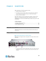
1
CommandCenter Secure Gateway Deployment Guide Release 4.0 Copyright © 2008 Raritan, Inc. DSD-0G-E July 2008 255-80-5160-00 This document contains proprietary information that is protected by copyright. All rights reserved. No part of this document may be photocopied, reproduced, or translated into another language without express prior written consent of Raritan, Inc. © Copyright 2008 Raritan, Inc., CommandCenter®, Dominion®, Paragon® and the Raritan company logo are trademarks or registered trademarks of Raritan, Inc. All rights reserved. Java® is a registered trademark of Sun Microsystems, Inc. Internet Explorer® is a registered trademark of Microsoft Corporation. Netscape® and Netscape Navigator® are registered trademarks of Netscape Communication Corporation. All other trademarks or registered trademarks are the property of their respective holders. FCC Information This equipment has been tested and found to comply with the limits for a Class A digital device, pursuant to Part 15 of the FCC Rules. These limits are designed to provide reasonable protection against harmful interference in a commercial installation. This equipment generates, uses, and can radiate radio frequency energy and if not installed and used in accordance with the instructions, may cause harmful interference to radio communications. Operation of this equipment in a residential environment may cause harmful interference. VCCI Information (Japan) Raritan is not responsible for damage to this product resulting from accident, disaster, misuse, abuse, non-Raritan modification of the product, or other events outside of Raritan's reasonable control or not arising under normal operating conditions. C UL US LI STED 1F61 I.T.E. Contents Chapter 1 Introduction 5 Prerequisites .................................................................................................................................. 5 Intended Audience ......................................................................................................................... 5 CC NOC Deployment and Paragon Integration............................................................................. 6 Chapter 2 Pre-Deployment Planning 7 Prepare Infrastructure .................................................................................................................... 8 Basic Requirements for Dominion Products........................................................................ 9 Prepare Network ............................................................................................................................ 9 Allocate IP Addresses for Raritan Devices..........................................................................9 Open Ports for Firewall or IP Port Filters............................................................................. 9 Prepare Target Servers ............................................................................................................... 10 Target Server Video Resolution ........................................................................................10 Prepare User PC.......................................................................................................................... 10 Install Java Runtime Environment .....................................................................................11 Chapter 3 Prepare Raritan Devices 12 Local Console or Web Browser Access.......................................................................................12 Default IP Address and Logins .................................................................................................... 13 Direct Access is Restricted .......................................................................................................... 13 Fall Back to Stand-alone Mode.................................................................................................... 13 Minimum Firmware Version ......................................................................................................... 14 Preparing Dominion Devices for CC-SG Management ...............................................................14 Dominion KX Devices........................................................................................................14 Dominion KX II Devices.....................................................................................................17 Dominion KX II-101 ...........................................................................................................18 Dominion SX Devices........................................................................................................30 Dominion KSX Devices .....................................................................................................32 Dominion KSX II Devices ..................................................................................................34 Preparing Dominion PX Devices for CC-SG Management .........................................................39 Connecting the Dominion PX to a Computer ....................................................................41 Connecting the Dominion PX to Your Network .................................................................42 Configuring the Dominion PX for Network Connectivity ....................................................42 Preparing IP-Reach Devices for CC-SG Management ...............................................................46 IP Reach TR or M Series...................................................................................................46 iii Contents Chapter 4 Install CC-SG 50 1. Rack Mount the CC-SG Unit.................................................................................................... 50 2. Physical Connections .............................................................................................................. 50 3. Set IP Address of CC-SG ........................................................................................................ 52 Appendix A Installation Template 53 Blank Template ............................................................................................................................ 53 Sample Template......................................................................................................................... 55 Appendix B Remote Power Management 59 Device Configurations for Power Control in CC-SG ....................................................................59 Example: Remote Power Management Using SX, KX, and Powerstrip......................................60 CC-SG Configuration.........................................................................................................60 Example: Remote Power Management for Multiple Power Connections....................................61 CC-SG Configuration.........................................................................................................61 Appendix C CC-SG and Network Configuration 62 Required Open Ports for CC-SG Networks: Executive Summary...............................................62 CC-SG Communication Channels ...............................................................................................63 CC-SG and Raritan Devices..............................................................................................63 CC-SG Clustering ..............................................................................................................64 Access to Infrastructure Services ......................................................................................65 PC Clients to CC-SG .........................................................................................................65 PC Clients to Nodes ..........................................................................................................66 CC-SG and Client for IPMI, iLO/RILOE, DRAC, RSA .......................................................66 CC-SG and SNMP.............................................................................................................67 CC-SG and CC-NOC.........................................................................................................67 CC-SG Internal Ports.........................................................................................................68 CC-SG Access via NAT-enabled Firewall .........................................................................68 iv Chapter 1 Introduction CommandCenter Secure Gateway (CC-SG) provides a hardware-based management solution engineered to consolidate secure access and control of IT devices. It provides centralized management of serial, KVM and power control devices in multiple data centers, branch offices and remote locations via a single, secure browser-based access. Users can access target servers and systems (nodes) that are connected to Raritan devices, such as Dominion KX or IP-Reach. In this guide, the term “Raritan devices” refers to the following equipment: • Dominion KX • Dominion KX II • Dominion KX101 • Dominion KSX • Dominion SX • IP-Reach (all models) Within CC-SG, target servers and systems are called nodes. In This Chapter Prerequisites..............................................................................................5 Intended Audience.....................................................................................5 CC NOC Deployment and Paragon Integration ........................................6 Prerequisites This guide provides comprehensive instructions on deploying Raritan devices that are managed by CC-SG. Additional installation information on Raritan devices and CC-SG is available on the User Manuals & Quick Setup Guides CD-ROM, or online in the Support section of the Raritan website. Intended Audience This guide is written for installation engineers and technicians installing Raritan devices and provides installation procedures and all relevant information that is needed to install CC-SG and its managed devices for a typical environment. Please read all pertinent information in this guide before starting installation of any products. 5 Chapter 1: Introduction CC NOC Deployment and Paragon Integration CommandCenter NOC (CC NOC) and integration with Paragon II systems (P2-SC) are NOT covered in this guide. See the Deployment Guide that came with your CC NOC or P2-SC unit. 6 Chapter 2 Pre-Deployment Planning In This Chapter Prepare Infrastructure................................................................................8 Prepare Network........................................................................................9 Prepare Target Servers ...........................................................................10 Prepare User PC .....................................................................................10 7 Chapter 2: Pre-Deployment Planning Prepare Infrastructure Planning for the installation of your CC-SG and Raritan devices is very much like the planning for any other new systems in your datacenter. HVAC, power, physical access and mounting, network, cabling, and remote access must be considered. 8 • Heating and Cooling. It is essential to have adequate heating and cooling so that the equipment can operate in the temperature and humidity ranges for which it has been designed. Please refer to the specific product User Guide for additional information. • Power Supplies. Raritan products have auto-ranging power supplies so they can function in most datacenter environments. Some products have dual power supplies for power redundancy such as CC-SG. • Serial Device Connectivity. Uses either a straight through Ethernet cable or a crossover cable. Sun and Cisco serial interfaces typically use a crossover cable that connects directly to an RJ45 port. Other serial targets typically use a standard Ethernet cable attached to a DB9 or DB25 serial connector. • Cabling Requirements. Depends on the specific products deployed as well as datacenter distances and structured cabling design. Cables should be tested and within distance limitation guidelines for each device. IP-Reach, Dominion KSX, and Dominion KX101 devices should use Raritan-supplied KVM cabling. • LAN Ports. All Raritan devices covered in this guide have an auto-sensing 10/100 Base-T network port for attachment to your LAN. Some devices, including CC-SG, have dual-LAN ports for redundancy. Some Raritan devices also have gigabit Ethernet. • Remote Access for Raritan Devices. External remote access for some devices, in an emergency situation, can be accommodated via modem. Appropriate phone lines and modems should be obtained prior to installation. • Rack Mounts. Most Raritan devices include rack mounts for installation into datacenter cabinets and racks. Some devices, such as the Dominion SX4 and SX8, have optional rack-mount kits available. Please refer to the specific product User Guide or Deployment Guide for additional information. Chapter 2: Pre-Deployment Planning Basic Requirements for Dominion Products All Dominion products include rack mounts for installation in standard 19 inch cabinets. Standard included power cables are for 110 VAC/15 amp receptacles. Power supplies are 110/220 auto switching. • Dominion KX devices use standard CAT 5 or better cabling for connecting between the target and Dominion KX. The standard supported distance is 150 feet. Each target requires a CIM. • Dominion SX serial devices use standard CAT 5 or better cabling for connecting to serial devices. Raritan DB9/DB25-RJ45 adapters need to be connected to the device serial port for connection to the CAT 5 cable. Serial devices that use a RJ45 rollover interface should be connected directly to the Dominion SX with a rollover cable. This applies to most Cisco and Sun products. Use a 1 foot Raritan rollover adapter cable to allow the use of standard CAT 5 or better cabling for these type devices. Prepare Network Network preparation is essential for Raritan devices and CC-SG to function properly over your LAN/WAN. Allocate IP Addresses for Raritan Devices IP addresses must be allocated and statically assigned for all Raritan devices. To eliminate any possible address conflicts, first test any allocated IP address to make sure it is not currently being used. See Installation Template (on page 53) to document the IP addresses, default gateway, subnet mask, and administrative username and password for each device. This information is needed during setup and configuration. Note: Dominion devices support 10/100 Ethernet. It is strongly recommended that all Dominion KX devices be hard coded on both the Dominion KX and Ethernet switch to eliminate auto negotiation problems. Open Ports for Firewall or IP Port Filters Raritan devices are accessed from a standard web browser. If a firewall or IP port filter is enabled between the user PC, CC-SG, and Raritan devices, ports must be opened to allow connectivity. See CC-SG and Network Configuration (on page 62). 9 Chapter 2: Pre-Deployment Planning Prepare Target Servers Target servers and systems that attach to KVM over IP Raritan devices, for example, Dominion KX, Dominion KX II, Dominion KX101, Dominion KX2-101, Dominion KSX, Dominion KSX II, and IP-Reach, must have mouse and video settings adjusted for optimal performance and responsiveness over an IP network. This allows CC-SG to remotely control the target systems. Adjust the mouse and video settings before connecting the target to the Raritan device. Target Server Video Resolution Ensure that each target server's video resolution and refresh rate is supported and that the signal is non-interlaced. Please refer to the specific Raritan product's User Guide for supported video resolutions. All Raritan devices support at least the following video resolutions: 640 x 480 @ 60Hz 800 x 600 @ 56Hz 1152 x 864 @ 60Hz 640 x 480 @ 72Hz 800 x 600 @ 60Hz 1152 x 864 @ 70Hz 640 x 480 @ 75Hz 800 x 600 @ 72Hz 1152 x 864 @ 75Hz 640 x 480 @ 85Hz 800 x 600 @ 75Hz 1152 x 900 @ 66Hz 800 x 600 @ 85Hz 1280 x 960 @ 60Hz 720 x 400 @ 70Hz 720 x 400 @ 85Hz 1024 x 768 @ 60Hz 1024 x 768 @ 70Hz 1280 x 1024 @ 60Hz 1024 x 768 @ 75Hz 1024 x 768 @ 77Hz 1024 x 768 @ 85Hz Prepare User PC Raritan devices and CC-SG are accessed via a web browser from a user's PC. The browser must have the correct version of Java Runtime Environment (JRE) installed to function correctly with Raritan devices. You must also disable all pop-up blockers and any firewall software that is enabled by default. 10 Chapter 2: Pre-Deployment Planning Install Java Runtime Environment Install the currently approved version of Java on all PCs that are using CC-SG. You can download Java from http://java.sun.com/j2se/index.jsp http://java.sun.com/j2se/index.jsp. For the most current listing of compatible browsers, PC platforms, and JRE versions, please refer to the Compatibility Matrix for your version of CC-SG in the Support section of the Raritan website. 11 Chapter 3 Prepare Raritan Devices The Raritan devices must be configured and installed on the network prior to adding the devices to CC-SG. Basic installation and configuration consists of the following steps: 1. Attach power cord and local access method, such as KVM drawer or laptop. 2. Set device IP address. 3. Connect devices to network. 4. Attach CIMs to targets, and then attach targets to devices. Target servers should be powered on and connected to CIMs and CIMs should be connected to the Raritan device before configuring the ports in CC-SG. Otherwise, the blank CIM name overwrites the CC-SG port name. Servers may need to be rebooted after you connect the CIM, depending on the type of CIM. Note: The Dominion KX101 and KX2-101 are attached directly to one target and therefore, does not require a CIM. 5. Document the device IP address, device name, administrative username and password, device location, and attached servers and systems (port number, system name, system type). You can use the form provided in Installation Template (on page 53) as a guide. You will need this information when you add the devices to CC-SG. In This Chapter Local Console or Web Browser Access.................................................. 12 Default IP Address and Logins ............................................................... 13 Direct Access is Restricted ..................................................................... 13 Fall Back to Stand-alone Mode............................................................... 13 Minimum Firmware Version .................................................................... 14 Preparing Dominion Devices for CC-SG Management .......................... 14 Preparing Dominion PX Devices for CC-SG Management .................... 39 Preparing IP-Reach Devices for CC-SG Management........................... 46 Local Console or Web Browser Access Most Raritan devices allow direct access via a local console to which you can attach a keyboard, video, and mouse, or via a web browser when operating in standalone mode (without CC-SG). You can use either of these mechanisms to access administrative functions for configuration of the Raritan device. 12 Chapter 3: Prepare Raritan Devices Default IP Address and Logins • All Raritan IP-based products use the default IP address: 192.168.0.192. • The default IP address to access CC-SG administrative functions is 192.168.0.192/admin. • Most Raritan products use the default username admin and password raritan. • CC-SG's default login for versions 3.1 and higher is username admin and password raritan. CC-SG versions prior to 3.1 use the default username ccroot and password raritan0. Direct Access is Restricted Once a device is added to CC-SG, direct access to that device is prevented (except for Dominion SX devices, which you can configure to allow local access even while under CC-SG control). Restricting direct access helps keep your devices secure. Because of this security feature, it is very important to configure any options and settings appropriately before adding devices to CC-SG. To gain direct access to a device under CC-SG management: Use CC-SG's Pause Management feature to release a device from CC-SG management temporarily. See Raritan's CommandCenter Secure Gateway Administrator Guide for additional information. Fall Back to Stand-alone Mode Should CC-SG become unreachable from a device for the amount of time configured as the heartbeat timeout (loss of connectivity by either a network or CC-SG failure), the device automatically falls back to stand-alone mode. This feature allows the device to continue functioning even during network outages. This feature also allows you to access the device from the console port or a browser to perform administrative functions if needed (disconnect the device from the network and use the console or a crossover network cable for browser access). Make sure all devices have a suitable configuration for stand-alone mode should you need to access them during a network outage. 13 Chapter 3: Prepare Raritan Devices Minimum Firmware Version Raritan devices managed by CC-SG must have the current minimum firmware version to work correctly with CC-SG. Once you add Raritan devices to CC-SG, you can perform firmware upgrades from the CC-SG interface. See the Compatibility Matrix for CC-SG in the Support section of the Raritan website. Preparing Dominion Devices for CC-SG Management Prior to installation, please read the entire section for each device that will be managed by CC-SG. Note: Consult the Quick Setup Guides for Dominion KX, Dominion KX II, Dominion KX101, Dominion KX2-101, Dominion SX, Dominion KSX, and Dominion KSX2 for additional information on configuration. Dominion KX Devices The following section provides you with the necessary background information and steps to install and configure Raritan Dominion KX units to conform to CC-SG's requirements. Note: Be sure to document the device name, IP address, administrative username and password, and attached systems (port number, type, system name) in Installation Template (on page 53). Diagram Key AC Power Cord Modem Port (optional) LAN 1 Network Port 14 Chapter 3: Prepare Raritan Devices Local Access Console Ports Server Ports Attach Power Cord and Local Console 1. Connect the included AC power cord to the Dominion KX unit and plug into an AC Power Outlet. 2. Attach a multisync VGA monitor, mouse, and keyboard to the ports labeled Local User using either a PS/2 keyboard and mouse or a USB keyboard and mouse. 3. Power ON the Dominion KX unit. The device powers up and begins the boot process. Set Dominion KX IP Address After completing the boot process, you will see the Dominion KX's local access On Screen Display (OSD). 1. Log in with the default username (admin) and password (raritan). 2. Press the F5 key to activate the Administrative Menu. 3. Select option 3 Network Settings, and then press ENTER to display the screen. 4. Specify the IP address, subnet mask and default gateway for this Dominion KX unit. 5. Press the S key to save the settings. The Dominion KX unit will automatically reboot. 15 Chapter 3: Prepare Raritan Devices Connect to Network and Attach Servers 1. [Optional] Use a straight-through serial cable to connect an external modem. 2. Connect one end of a straight-through Ethernet cable (included) to the port labeled LAN1 on the Dominion KX, and the other end to a network switch or router. 3. [Optional] For Ethernet redundancy, use a straight-through Ethernet cable to connect the LAN2 port to another network switch or router. Should the Ethernet connectivity on LAN1 become unavailable, Dominion KX will failover to this port with the same TCP/IP settings at all other times, this port will be disabled. 4. [Optional] Attach a keyboard and mouse (either PS/2 or USB), and a multi-sync monitor to the corresponding ports in the back of Dominion KX marked Local User. The Local User Console is used to access servers directly from the rack. 5. Connect one end of a standard, straight through UTP cable (Cat5 / 5e / 6) to an unoccupied server port; connect the other end to the RJ45 ports on a Dominion KX CIM. 6. Connect the remaining ports on the CIM to the corresponding KVM ports of a server that you want to manage using the Dominion KX. 7. Repeat these steps to connect all servers that you want to manage with this Dominion KX. 16 Chapter 3: Prepare Raritan Devices Dominion KX II Devices The following section provides you with the necessary background information and steps to install and configure Raritan Dominion KX II units to conform to CC-SG's requirements. Note: Be sure to document the device name, IP address, administrative username and password, and attached systems (port number, type, system name) in Installation Template (on page 53). Attach Power Cord and Local Console 1. Attach the included AC power cord to the Dominion KX II and plug into an AC power outlet. 2. Attach a multi-sync VGA monitor, mouse, and keyboard to the respective Local User ports using either a PS/2 or USB keyboard and mouse. Set Dominion KX II IP Address 1. Power ON the Dominion KX II using the power switch at the back of the unit. Please wait for the Dominion KX II unit to boot. (A beep signals that the boot is complete.) 2. Once the unit has booted, the KX II Local Console is visible on the monitor attached to the Dominion KX II local port. Type the default username (admin) and password (raritan) and click Login. The Change Password screen is displayed. 17 Chapter 3: Prepare Raritan Devices 3. Follow the prompts to change the default password. Please refer to Raritan's KX II User Guide for details. Be sure to make a note of the new password. 4. You will receive confirmation that the password was successfully changed. Click OK. The Port Access page is displayed. 5. Select Device Settings > Network Settings. 6. Specify a meaningful Device Name for your Dominion KX II unit; up to 16 alphanumeric characters, special characters, and no spaces. 7. Select None (Static IP) from the IP auto configuration drop-down list: 8. Type the TCP/IP parameters for your Dominion KX II unit: IP address, Subnet mask, Gateway IP address, Primary DNS server IP address, and (optional) Secondary DNS server IP address. 9. Click OK to save the settings. Restart the Dominion KX II unit. Connect to Network and Attach Servers Dominion KX II uses standard UTP cabling (Cat5/5e/6) to connect to each target server. 1. Connect a standard Ethernet cable (included) from the network port labeled LAN1 to an Ethernet switch, hub, or router. 2. To connect a target server to Dominion KX II, connect the appropriate Computer Interface Module (CIM). Please refer to Raritan's Dominion KX II User Guide for details. 3. Attach the HD15 video connector of your CIM to the video port of your target server. Ensure that your target server's video has already been configured to a supported resolution and refresh rate. For Sun servers, also ensure that your target server's video card has been set to output standard VGA (H-and-V sync) and not composite sync. 4. Attach the keyboard/mouse connector of your CIM to the corresponding ports on your target server. Using a standard straight-through UTP (Cat5/5e/6) cable, connect the CIM to an available server port on the back of your Dominion KX II unit. Dominion KX II-101 The following section provides you with the necessary background information and steps to install and configure Raritan Dominion KX II-101 units to conform to CC-SG's requirements. Note: Be sure to document the device name, IP address, administrative username and password, and attached systems (port number, type, system name) in Installation Template (on page 53). 18 Chapter 3: Prepare Raritan Devices Connecting the Dominion KX II-101 The Dominion KX II-101 has the physical connections described in the diagram below: 19 Chapter 3: Prepare Raritan Devices 20 Chapter 3: Prepare Raritan Devices 1 Attached Monitor and PS/2 Cable (See item 3.). 2 Mini-USB Port. Use to connect the device to the target server with the included USB cable if not using the attached PS/2 cable. A USB connection must be used in order to utilize the Absolute Mouse Sync or Virtual Media features. 3 Attached Monitor and PS/2 Cable. Use to connect the device to a monitor and to a target server if not using the USB cable. 4 LOCAL USER port. Use to connect a local keyboard, video, and mouse directly to the target server using an optional PS/2 cable. 5 Ethernet LAN/PoE Port. Provides LAN connectivity and power if using a PoE LAN connection. 6 Power Connector. Connects the power supply if you are not using a PoE (power over Ethernet) LAN connection. 7 Backlit LED power ON and boot-up indicator. Provides feedback on the operating status of the device. 8 Admin Port. Use to do one of the following: Configure and manage the device with a terminal emulation program on your PC. Configure and manage a power strip. Connect an external modem to dial into the device. Connecting to the Target Server The Dominion KX II-101 can use either the integrated PS/2 cables or the included USB cable to connect to the target server. Before connecting, configure your target server's video to a supported resolution and refresh rate as described in Setting Server Video Resolution in Raritan's Dominion KX II-101 User Guide. PS/2 Configuration To configure the Dominion KX II-101 for use with a PS/2 target server: 1. Use the attached PS/2 keyboard, video, and mouse cabling to connect the Dominion KX II-101 to the target server. 2. Use the optional PS/2 cabling to attach the local keyboard, video, and mouse to the Local User port of the Dominion KX II-101. Note: The Dominion KX II-101 must be powered for the Local User port to function. 21 Chapter 3: Prepare Raritan Devices 3. If you require Virtual Media (VM) connectivity, connect the mini-USB connector to the Dominion KX II-101 and the USB connector to any USB port on the target server. 22 1 Integrated PS/2 keyboard, video, and mouse connections from Dominion KX II-101 to target server. 2 Dominion KX II-101. 3 Video connection to local monitor (optional cable). 4 Local monitor. 5 PS/2 connection from Dominion KX II-101 to mouse (optional cable). 6 PS/2 connection from Dominion KX II-101 to keyboard (optional cable). 7 Target server. 8 Included mini-USB to USB connector from Dominion KX II-101 to target server for Virtual Media connectivity. Chapter 3: Prepare Raritan Devices USB Configuration To configure the Dominion KX II-101 for use with a USB target server: 1. Connect the mini-USB connector to the Dominion KX II-101 and the USB connector to a USB port on the target server. 2. Use the included PS/2 DKX2-101-LPKVMC cabling to attach only the local video to the Local User port of the Dominion KX II-101. Note: The Dominion KX II-101 must be powered for the Local User port to function. 3. Use USB cables to connect the keyboard and mouse directly to the target server. 1 Included mini-USB to USB cable from Dominion KX II-101 to target server. 2 Dominion KX II-101. 23 Chapter 3: Prepare Raritan Devices 3 Video connection to local monitor (optional cable). 4 Local monitor. 5 USB connection from target server to mouse. 6 USB connection from target server to keyboard. 7 Target server. Connecting to the Network Connect a standard Ethernet cable from the network port labeled LAN to an Ethernet switch, hub, or router. The LAN LEDs that appear above the Ethernet connection indicate Ethernet activity. The yellow one blinks while the Dominion KX II-101 is in use, indicating IP traffic at 10Mbps. The green light indicates a 100Mbps connection speed. Powering the Dominion KX II-101 The Dominion KX II-101 can be powered with either the included standard AC power pack or by PoE (Power over Ethernet). • For standard AC power, plug the included AC power adaptor kit into the Power Port and plug the other end into a nearby AC power outlet. • For PoE, attach a 10/100Mbps cable to the LAN port, and plug the other end into a PoE-provisioned LAN. After Dominion KX II-101 is powered ON, it goes through a boot-up sequence, during which the blue Raritan-logo LED will blink for about 45 seconds. Upon successful boot-up, the back-lit LED remains lit. Using the Admin Port The Admin port enables you to perform configuration and setup for the Dominion KX II-101 using a terminal emulation program like HyperTerminal. Plug the min-DIN end of the included serial cable into the Admin port of the Dominion KX II-101 and plug the DB9 end into a serial port on your PC or laptop. The serial port communication settings should be configured to: to 115,200 Baud, 8 data bits, 1 stop bit, no parity, and no flow control. For information about configuring the Dominion KX II-101 using the ADMIN port, see Using a Terminal Emulation Program in Raritan's Dominion KX II-101 User Guide. 24 Chapter 3: Prepare Raritan Devices Configuring the Dominion KX II-101 The Dominion KX II-101 can be configured in two ways: • Using the web-based Dominion KX II-101 Remote Console, which requires the unit to have a network connection to your workstation. • Using a terminal emulation program like HyperTerminal, which requires a direct connection from the unit's ADMIN port to your workstation. The cable for this connection is included with the Dominion KX II-101. This section describes both ways of configuring the Dominion KX II-101. Using the Remote Console The Dominion KX II-101 Remote Console is a web-based application that enables you to configure the unit prior to use. Before configuring the Dominion KX II-101 using the Remote Console, you must have both your workstation and the unit connected to a network. To configure the Dominion KX II-101, you: • Set a new password to replace the default • Assign an IP address Setting a New Password When you first log into the Remote Console, you are prompted to set a new password to replace the default. Then you can configure the Dominion KX II-101. 1. Log on to a workstation with network connectivity to your Dominion KX II-101 unit. 2. Launch a supported Web browser such as Internet Explorer (IE) or Firefox. 3. In the address field of the browser, enter the default IP address of the unit: 192.168.0.192 4. Press Enter. The login page opens. 5. Enter the user name admin and the password raritan. 6. Click Login. The Change Password page is displayed. 7. Type raritan in the Old Password field. 8. Type a new password in the New Password field; retype the new password in the Confirm New Password field. Passwords can be up to 64 characters long and can consist of English alphanumeric and printable special characters. 9. Click Apply. 25 Chapter 3: Prepare Raritan Devices You will receive confirmation that the password was successfully changed. 10. Click OK. The Port Access page opens. Assigning an IP Address 1. In the Dominion KX II-101 Remote Console, choose Device Settings > Network Settings. The Network Basic Settings page opens. 2. In the Device Name field, specify a meaningful name for your Dominion KX II-101 unit; up to 16 alphanumeric and special characters, no spaces. 3. Select the IP configuration from the IP auto configuration drop-down list: 26 None (Static IP). This is the default and recommended option because the Dominion Dominion KX II-101 is an infrastructure device and its IP Address should not change. This option requires that you manually specify the network parameters. DHCP. With this option, network parameters are assigned by the DHCP server each time the Dominion KX II-101 is booted. Chapter 3: Prepare Raritan Devices Using a Terminal Emulation Program You can use the Admin serial console with a terminal emulation program like HyperTerminal to set the following configuration parameters for the Dominion KX II-101: • IP address • Subnet mask address • Gateway address • IP access control • LAN speed • LAN interface mode To use a terminal emulation program with the Dominion KX II-101, you must first connect the included RS-232 serial cable from the Admin port on the Dominion KX II-101 to the COM1 port on your PC. See Using the Admin Port (on page 24). For demonstration purposes, the terminal emulation program described in this section is HyperTerminal. You can use any terminal emulation program. To use a terminal emulation program to configure the Dominion KX II-101: 1. Connect the Dominion KX II-101 to a local PC using the included RS-232 serial cable. Connect to the Admin port on the Dominion KX II-101 and the COM1 port on the PC. 2. Launch the terminal emulation program you want to use to configure the Dominion KX II-101. 3. Set the following port settings in the terminal emulation program: Bits per second: 115200 Data bits: 8 Parity: None Stop bits: 1 27 Chapter 3: Prepare Raritan Devices Flow control: None 4. Connect to the Dominion KX II-101. The login screen appears. 5. Type the administrator user name and press Enter. You are prompted to enter your password. 6. Type your password and press Enter. The Admin Port prompt appears. 28 Chapter 3: Prepare Raritan Devices 7. At the Admin Port > prompt, type config and press Enter. 8. At the Config > prompt, type network and press Enter. 9. To view the current interface settings, at the Interface > prompt, type interface and press Enter. 10. To configure new network settings, at the Network prompt, type interface followed by one of the following commands and its appropriate argument (option), then press Enter. Command Argument Options ipauto none|dhcp none - Enables you to manually specify an IP address for the device. You must follow this option with the ip command and the IP address, as shown in the following example: interface ipauto none ip 192.168.50.12 dhcp - Automatically assign an IP address to the device on startup. ip IP address The IP address to assign to the device. To manually set an IP address for the first time, this command must be used with the ipauto command and the none option. See ipauto for information. After you have manually assigned an IP address once, you can use the ip command alone to change the IP address. mask subnetmask The subnet mask IP address. gw IP address The gateway IP address mode mode The Ethernet mode. You have the following choices: auto - Automatically sets speed and interface mode based on the network. 10hdx - 10 Mbs, half duplex. 10fdx - 10 Mbs, full duplex 100hdx - 100 Mbs, half duplex 100fdx - 100 Mbs, full duplex When you have successfully changed a setting, you see a confirmation message like the following: 1. When you are finished configuring the Dominion KX II-101, type logout at the command prompt and press Enter. You are logged out of the command line interface. 29 Chapter 3: Prepare Raritan Devices Dominion SX Devices The following section provides you with the necessary background information and steps to install and configure Raritan Dominion SX units to conform to CC-SG's requirements. Note: Be sure to document the device name, IP address, administrative username and password, and attached systems (port number, type, system name) in Installation Template (on page 53). Attach Power Cord and Installation Computer 1. Obtain a computer with a network card and a crossover network cable. This computer will be referred to as the installation computer. 2. Connect the crossover network cable to the primary LAN connection on the rear panel of the unit. On models with two Ethernet interfaces, the primary LAN is LAN 1. 3. Connect the other end of the crossover network cable to the network port on the installation computer. 4. Connect the included AC power cord to the Dominion SX unit and plug into an AC Power Outlet. 5. Power ON the Dominion SX unit. Note: The SX unit performs a hardware self-test, indicated by the green light on the back of the unit, and then starts the software boot sequence. The boot sequence is complete when the green light goes on and remains illuminated. Set Dominion SX IP Address 1. Access the SX unit through your installation computer's browser on the same subnet by typing the default URL https://192.168.0.192 into the address field. 2. Log in with the default username (admin) and password (raritan). 3. Follow the prompts to change the default password. Be sure to make a note of the new password. 4. Click the Setup tab to display the Configuration and Logging topics. 5. Click the Network section of the Setup Configuration screen. 6. Type the data in the following fields: IP Address: Network address for this unit; Subnet Mask: Subnet mask for the network where this unit will reside; Gateway IP Gateway: Default gateway for this unit. 7. Accept all other default values or change as needed. 8. Click OK to save the settings. The SX unit reboots automatically once it has been configured. 30 Chapter 3: Prepare Raritan Devices Connect to Network and Attach Serial Devices 1. Power OFF the SX unit. 2. Disconnect from the installation computer, and move the Dominion SX to the location where it will be added to CC-SG. 3. Connect one end of a straight-through Cat5 cable to the SX. 4. Connect the other end of the Cat5 cable to the network. 5. To attach a device with a standard DB9 or DB25 serial console port, connect one end of a standard Cat5 Ethernet cable to a serial console port on the Dominion SX. 6. Connect the other end to a Raritan Nulling Serial Adapter (p/n ASCSDB9F, ASCSDB9M, ASCSDB25F, ASCSDB25M) as appropriate. 7. Connect the adapter to the console port of the device. 31 Chapter 3: Prepare Raritan Devices Dominion KSX Devices The following section provides you with the necessary background information and steps to install and configure Raritan KSX units to conform to CC-SG's requirements. Note: Be sure to document the device name, IP address, administrative username and password, and attached systems (port number, type, system name) in Installation Template (on page 53). Diagram Key AC Power Cord Network Port, Standard Cat5 Ethernet Cable, included Power Port for Raritan Power Control Unit (p/n PCR8, PCS12, PCS20), Standard Cat5 Ethernet Cable Analog Telephone Line, Telephone Cable, included Serial Console Ports, Standard Cat5 Ethernet Cable with Nulling Serial Adapter (p/n ASCSDBxxx) 32 Chapter 3: Prepare Raritan Devices Diagram Key Serial Console Ports. Most Cisco RJ45 or Sun RJ45 Serial Ports require Rollover Cable (p/n CRLVR-15) KVM Console Ports, KVM Console Cable (p/n CCPTxxx) * Connection to Local or Admin Port, depending on unit type. The local port and the Admin Port locations depend on the Dominion KSX model you purchased. Dominion KSX units have a label on the underside of the chassis identifying the hardware version. The models that read either: Chassis RX440-F/S-0B or -0D or Chassis RX880-F/S-0B or -0D have the Local Admin ports on the rear panel and Local Access Console ports on the front panel (behind the bezel). For those models with labels that read Chassis RX440-F/S-0F or Chassis RX880-F/S-0F; these locations are reversed: the Local Admin ports are found on the front panel (behind the bezel) and Local Access Console ports are on the rear panel. Please consult the labeling on your Dominion KSX unit to determine where the Local and Admin ports are located. Attach Power Cord and Local Console 1. Connect the included AC power cord to the Dominion KSX unit and plug into an AC Power Outlet. 2. Attach a PS/2 keyboard and multi-sync monitor to the corresponding local Admin Console ports on the Dominion KSX. Depending on your KSX model, the local Admin Console ports may be on the front (remove the front bezel by pulling it towards you) or the rear panel of your KSX unit. The local Admin Console is used during initial setup, but may be removed after setup is complete. 3. Power ON the Dominion KSX. Set Dominion KSX IP Address 1. After booting, the Dominion KSX displays the Setup Wizard on the Admin Console screen. Press B on the Admin Console keyboard to begin the initial configuration. 2. On the Network Configuration Screen, assign a unique name (for example, “Atlanta Office”) and IP Address parameters for this Dominion KSX unit. Please refer to Raritan's Dominion KSX User Guide for additional information on administrative parameters. 3. Press CTRL+S to save the settings. The Main Menu appears. 4. Press R to restart. 5. Press ENTER. 6. Press R again to reboot the Dominion KSX. 33 Chapter 3: Prepare Raritan Devices Connect to Network and Attach Serial Devices 1. [Optional] Disconnect the PS/2 keyboard and multi-sync monitor from the Admin Console ports. Or leave them attached for future monitoring or configuration. 2. Connect a standard Ethernet cable (included) from the network port labeled LAN1 to an Ethernet switch, hub, or router. 3. To attach a device with a standard DB9 or DB25 serial console port to Dominion KSX, connect one end of a standard Cat5 Ethernet cable to a serial console port on the Dominion SX. 4. Connect the other end of the Cat5 Ethernet cable to a Raritan Nulling Serial Adapter (p/n ASCSDB9F, ASCSDB9M, ASCSDB25F, ASCSDB25M) as appropriate. Dominion KSX II Devices The following section provides you with the necessary background information and steps to install and configure Raritan Dominion KSX II units to conform to CC-SG's requirements. Note: Be sure to document the device name, IP address, administrative username and password, and attached systems (port number, type, system name) in Installation Template (on page 53). Connect the Dominion KSX II to the power supply, network, local PC, KVM target servers, and serial targets. The numbers in the diagram correspond to the sections describing the connection. 34 Chapter 3: Prepare Raritan Devices 1. AC Power To connect the power supply: 1. Attach the included AC power cord to the Dominion KSX II and plug into an AC power outlet. 2. Network Ports Dominion KSX II provides two Ethernet ports for failover purposes (not for load-balancing). By default, only LAN1 is active and the automatic failover is disabled. When enabled, if the Dominion KSX II internal network interface or the network switch to which it is connected becomes unavailable, LAN2 will be enabled using the same IP address. To connect the network: 1. Connect a standard Ethernet cable (included) from the network port labeled LAN1 to an Ethernet switch, hub, or router. 2. To make use of the optional Dominion KSX II Ethernet failover capabilities: Connect a standard Ethernet cable from the network port labeled LAN2 to an Ethernet switch, hub, or router. Enable Automatic Failover on the Network Configuration screen. See Network Settings, LAN Interface Settings in the Raritan Dominion KSX II User Guide. Use both network ports only if you want to use one as a failover port. 3. Local User Port (local PC) and Local Admin Port For convenient access to KVM target servers and serial devices while at the rack, use the KSX II Local Access port. While the local port is required for installation and setup, it is optional for subsequent use. The local port provides the Dominion KSX II Local Console graphical user interface for administration and target server access. To connect the Local User port: Attach a multi-sync VGA monitor, mouse, and keyboard to the respective Local User ports (using either a PS/2 or USB keyboard and mouse). You can use the Local Admin port to connect the Dominion KSX II directly to a workstation to manage your serial targets and configure the system with a terminal emulation program such as HyperTerminal. The Local Admin port requires the use of a standard null modem cable. 35 Chapter 3: Prepare Raritan Devices 4. KVM Target Server Ports The Dominion KSX II uses standard UTP cabling (Cat5/5e/6) to connect to each target server. See Appendix A: Specifications in the Raritan Dominion KSX II User Guide. To connect a KVM target server to the Dominion KSX II: 1. Use the appropriate Computer Interface Module (CIM). Refer to Supported Operating Systems and CIMs in the Raritan Dominion KSX II User Guide for more information about the CIMs to use with each operating system. 2. Attach the HD15 video connector of your CIM to the video port of your KVM target server. Ensure that your target server's video has already been configured to a supported resolution and refresh rate. For Sun servers, also ensure that your target server's video card has been set to output standard VGA (H-and-V sync) and not composite sync. 3. Attach the keyboard/mouse connector of your CIM to the corresponding ports on your target server. Using a standard straight-through UTP (Cat5/5e/6) cable, connect the CIM to an available server port on the back of your Dominion KSX II unit. Note: The DCIM-USB G2 provides a small slide switch on the back of the CIM. Move the switch to P for PC-based USB target servers; move the switch to S for Sun USB target servers. A new switch position takes effect only after the CIM is power-cycled. To power-cycle the CIM, remove the USB connector from the target server and plug it back in a few seconds later. 5. Power Strip To connect the Dominion PX to the KSX II: 1. Plug one end of a Cat5 cable into the Serial port on the front of the Dominion PX. 2. Connect the other end of the Cat5 cable to either the Power Ctrl. 1 or Power Ctrl. 2 ports on the back of the KSX II. 3. Attach an AC power cord to the target server and an available power strip outlet. 4. Connect the power strip to an AC power source. 5. Power ON the KSX II unit. Important: When using CC-SG, the power ports should be inactive before attaching power strips that were swapped between the power ports. If not, there is a possibility that the number of power 36 Chapter 3: Prepare Raritan Devices outlets will not be correctly detected, especially after swapping 8 and 20 outlet power strip models. 6. Serial Target Ports To connect a serial target to the KSX II, use a Cat5 cable with an appropriate serial adapter. The following table lists the necessary Dominion KSX II hardware (adapters and/or cables) for connecting the Dominion KSX II to common Vendor/Model combinations. Vendor Device Console Connector DB9M Checkpoint Firewall Cisco PIX Firewall Cisco Catalyst RJ-45 Serial Connection ASCSDB9F adapter and a CAT 5 cable CRLVR-15 rollover cable; or CRLVR-1 adapter cable and a CAT5 cable CRLVR-1 cable for connecting a terminal port (RJ-45 Connector type) of CommandCenter Secure Gateway-48 models that have this connector to another CommandCenter Secure Gateway. Cisco Router DB25F ASCSDB25M adapter and a CAT 5 cable Hewlett Packard UNIX Server DB9M ASCSDB9F adapter and a CAT 5 cable Silicon Graphics Origin Sun SPARCStatio n DB25F ASCSDB25M adapter and a CAT 5 cable Sun Netra T1 RJ-45 CRLVR-15 cable; or CRLVR-1 adapter and a CAT5 cable Sun Cobalt DB9M Various Windows NT ASCSDB9F adapter and a CAT 5 cable Raritan RPCU RJ-45 CSCSPCS-10 cable or CSCSPCS-1 adapter cable Go to the following link to obtain a list of commonly used cables and adapters http://www.raritan.com/support http://www.raritan.com/support 37 Chapter 3: Prepare Raritan Devices Dominion KSX II Initial Configuration The first time you power up the Dominion KSX II unit, there is some initial configuration that you need to perform through the Dominion KSX II Local Console: • Change the default password. • Assign the IP Address. Assign an IP Address These procedures describe how to assign an IP Address using the Network Settings page. For complete information about all of the fields and the operation of this page, see Network Settings in the Raritan Dominion KSX II User Guide. 1. From the Dominion KSX II Local Console, select Device Settings > Network Settings. The Network Settings page opens. 2. Specify a meaningful Device Name for your Dominion KSX II unit; up to 16 alphanumeric characters, special characters, and no spaces. 3. Select the IP auto configuration from the drop-down list: 38 None (Static IP). This option requires that you manually specify the network parameters. This is the recommended option because the Dominion KSX II is an infrastructure device and its IP Address should not change. DHCP. With this option, network parameters are assigned by the DHCP server. Chapter 3: Prepare Raritan Devices 4. If you specify an IP configuration of None, type the TCP/IP parameters for your Dominion KSX II unit: IP address, Subnet mask, Gateway IP address, Primary DNS server IP address, and (optional) Secondary DNS server IP address. 5. Click OK. Your Dominion KSX II unit is now network accessible. Note: In some environments, the LAN Interface Speed & Duplex setting default of Autodetect (auto-negotiation) does not properly set the network parameters, resulting in network issues. In these instances, setting the Dominion KSX II LAN Interface Speed & Duplex field to 100 Mbps/Full Duplex (or whatever option is appropriate to your network) addresses the issue. Preparing Dominion PX Devices for CC-SG Management There are two ways to configure power control using powerstrips in CC-SG. 1. All supported Raritan-brand powerstrips can be connected to another Raritan device and added to CC-SG as a Powerstrip device. Raritan-brand powerstrips include Dominion PX and RPC powerstrips. Check the Compatibility Matrix for supported versions. To configure this type of managed powerstrip in CC-SG , you must know to which Raritan device the powerstrip is physically connected. See Configuring Powerstrips That Are Managed by Another Device in CC-SG. 2. Dominion PX powerstrips can be connected directly to the IP network and added to CC-SG as a PX device. If you have PX powerstrips connected directly to the IP network, they do not need to be connected to another Raritan device. 39 Chapter 3: Prepare Raritan Devices With both methods, you must add Managed Powerstrip interfaces to nodes to create power associations between the outlets and the nodes they power. See Interfaces for Managed Powerstrip Connections. Special Note about Dominion PX Regardless of which method you choose to configure a PX, you should configure all power associations using a single method, that is, as a powerstrip of the managed device or as a PX device, but not both. In addition, you can connect the PX to a managing device and configure power associations, and also connect the same PX device to the IP network so that you can use the PX web client to view and collect power data. See the Raritan Dominion PX User Guide, located in the Support section of the Raritan website under Firmware and Documentation. This section describes how to prepare a Dominion PX device for CC-SG management without being connected to another Raritan device. See Remote Power Management (on page 59) for information on adding Dominion PX and other supported Raritan powerstrips that are connected to another Raritan device. 40 Chapter 3: Prepare Raritan Devices Connecting the Dominion PX to a Computer You must connect the Dominion PX to a computer to configure it, using a serial connection between the Dominion PX and the computer. If you plan to use this connection to log into the CLP command line interface, leave the cable connected after the configuration is complete. The computer must have a communications program such as HyperTerminal or PuTTY. You will need the null-modem cable and connectors that were shipped with the Dominion PX. 1. Take the null-modem cable and connect the end with the RJ-45 connector to the port labeled Serial on the front of the Dominion PX. See the pictures for the location of this port on your Dominion PX. 41 Chapter 3: Prepare Raritan Devices Item # Description 1 LAN Port 2 Serial Port 3 Network Port 2. Plug the other end of the null-modem cable with the DB9 connector into the serial port (COM) of the computer. Connecting the Dominion PX to Your Network To use the Web interface to administer the Dominion PX, you must connect the Dominion PX to your local area network (LAN). 1. Take a standard Category 5e UTP cable and connect one end to the LAN port on the front of the Dominion PX. See Connecting the Dominion PX to a Computer (on page 41) for the location of this port on your size Dominion PX. 2. Connect the other end of the cable to your LAN. Configuring the Dominion PX for Network Connectivity Once the Dominion PX is connected to your network, you must provide it with an IP address and some additional networking information. 1. Go to the computer that you connected to the Dominion PX and open a communications program such as HyperTerminal or PuTTY. Make sure its port settings are configured as follows: 42 Chapter 3: Prepare Raritan Devices Bits per second = 9600 Data bits = 8 Stop bits = 1 Parity = None Flow control = None Note: The “Flow control” parameter must be set to “None” to ensure that the communications program will work correctly with the Dominion PX. 2. Point the communications program at the serial port connecting the Dominion PX, and open a terminal window. 3. Press the Enter key to display the opening configuration prompt. 4. Type config and press Enter to begin the configuration process. You are prompted to select an IP configuration method. 5. You must assign the Dominion PX an IP address. There are two ways to do this: Auto configuration - Select an autoconfiguration method such as dhcp or bootp and let the DHCP or BOOTP server provide the IP address. Static IP address - Select None and assign the Dominion PX a static IP address. You will be prompted for the address, network mask, and gateway. 43 Chapter 3: Prepare Raritan Devices Note: The Dominion PX's IP address is automatically displayed in the system prompt. The default IP address is 192.168.0.192. The default IP configuration method is DHCP, and the default IP address will be replaced by the address assigned by DHCP or BOOTP, or the static IP address you entered, as soon as the configuration process is complete. To use the factory default IP address, type in none as the IP autoconfiguration command, and accept the default value. The default IP address for static (none) configuration is 192.168.0.192. Type your selection and press Enter. You are prompted to enable IP access control. 6. By default, IP access control is NOT enabled. This disables the Dominion PX firewall. Leave the firewall disabled for the present; later you will enable the firewall from the Web interface and create firewall rules. See Configure the Firewall. Note: If you ever accidentally create a rule that locks you out of the Dominion PX, you can rerun the configuration program and reset this parameter to disabled to allow you to access the Dominion PX. 7. Press Enter. You are prompted to set the LAN interface speed. 44 Chapter 3: Prepare Raritan Devices 8. By default, the LAN interface speed is set to Auto, which allows the system to select the optimum speed. To keep the default, press Enter. To set the speed to 10 or 100 Mbps, type the speed you want and press Enter. You are prompted to select the duplex mode for the LAN interface. 9. By default, the LAN interface duplex mode is set to Auto, which allows the system to pick the optimum mode. Half duplex allows data to be transmitted to and from the Dominion PX, but not at the same time. Full duplex allows data to be transmitted in both directions at the same time. To keep the default, press Enter. To specify half or full duplex, type half or full and press Enter. You are prompted to confirm the information you just entered. 10. All the configuration parameters have now been entered. All the prompts are still displayed, so you can check the information you entered. Do one of the following: If the information is correct, type y and press Enter. The system completes the configuration and displays a message when the configuration is done. If one or more parameters are not correct, type n and press Enter. You are returned to the IP configuration prompt as shown in the screenshot of Step 4, and given the opportunity to correct each piece of information. When the information is correct, type y and press Enter to complete the configuration and return to the opening prompt. 45 Chapter 3: Prepare Raritan Devices If you want to terminate the configuration process, type c and press Enter. The configuration is cancelled and you are returned to the opening prompt. 11. If you entered y to confirm the configuration, a message appears when the configuration is complete. You will be returned to the opening prompt. You are now ready to begin using your Dominion PX. Note: The IP address configured takes about 15 seconds to take effect for the device connected via serial line, or even longer if configured over DHCP. Preparing IP-Reach Devices for CC-SG Management The following section provides you with the necessary background information and steps to install and configure Raritan IP-Reach units to conform to CC-SG's requirements. Note: Be sure to document the device name, IP address, administrative username and password, and attached systems (port number, type, system name) in Installation Template (on page 53). Please refer to Raritan's IP-Reach Quick Setup Guide for additional information. IP Reach TR or M Series Attach Power Cord and Local Console 1. Connect the included AC power cord to the IP-Reach unit. 2. Attach a PS/2 keyboard and multi-sync monitor to the corresponding ports in the back of the IP-Reach marked Admin Console. 46 Chapter 3: Prepare Raritan Devices 3. Power ON the IP-Reach. Set IP Reach IP Address: 1. After the system boots, IP-Reach displays the Setup Wizard on the Admin Console screen. 47 Chapter 3: Prepare Raritan Devices Note: During initial configuration, the IP-Reach Setup Wizard helps you quickly set up IP-Reach for the first time. The IP-Reach Setup Wizard appears only when accessing the Administrative Menus on a non-configured IP-Reach. 48 Chapter 3: Prepare Raritan Devices 2. Press B on the Admin Console keyboard to begin configuring IP-Reach. 3. Based on your configuration, type the requested information. Note: Do not obtain the IP-Address via DHCP. Obtain the IP-Address, the subnet mask, and default gateway from your network system administrator. 4. Press CTRL+S to save the settings. 5. On the Network Configuration Screen, assign a unique name (e.g. Server_Room) and IP Address parameters for IP-Reach. 6. The Main Menu appears. Browse through the Admin Console options to configure IP-Reach as appropriate to your environment. Please refer to Raritan's IP-Reach User Guide for additional information. Connect to Network and Attach Servers or Switches: 1. Connect a standard Ethernet cable from the network port to an Ethernet switch, hub, or router. 2. Connect the included CCP20 cable(s) from the KVM In port on the IP Reach unit to the KVM console of server or KVM switch to be accessed remotely. 49 Chapter 4 Install CC-SG Basic installation of CC-SG comprises 3 steps: 1. Rack-mount the CC-SG unit. 2. Physically connect all cables. Each CC-SG model has a different setup. Follow the instructions for your CC-SG model number. 3. Set the CC-SG IP address. Next Steps: When you have completed the installation, please refer to Raritan's CC-SG Administrators Guide for additional information on configuring your CC-SG. Use Guided Setup to easily set up your CC-SG environment. In This Chapter 1. Rack Mount the CC-SG Unit ...............................................................50 2. Physical Connections ..........................................................................50 3. Set IP Address of CC-SG ....................................................................52 1. Rack Mount the CC-SG Unit Follow the instructions on the Quick Setup Guide that came with your CC-SG unit. 2. Physical Connections Physical Connections for CC-SG E1 Units Numbers on the diagram below correspond to the step numbers in this procedure. 1. Connect the CAT 5 network LAN cable to the LAN 1 port on the rear panel of the CC-SG unit. Connect the other end of the cable to the network. 50 Chapter 4: Install CC-SG 2. Attach the 2 included AC power cords to the power ports on the rear panel of the CC-SG unit. Plug the other ends of the AC power cords into independent UPS protected outlets. 3. Connect a video monitor and keyboard using KVM cables to the corresponding ports on the rear panel of the CC-SG unit. Physical Connections for CC-SG V1 Units Numbers on the diagram below correspond to the step numbers in this procedure. 1. Connect the network LAN cable to the LAN 1 port on the rear panel of the CC-SG unit. Connect other end of cable to the network. 2. Attach the included AC power cord to the port on rear panel of the CC-SG unit. Plug the other end of the cord into an AC power outlet. 3. Power ON CC-SG by popping off front bezel and pressing the POWER button. 4. Connect a video monitor and keyboard using KVM cables to the corresponding ports on the rear panel of the CC-SG unit. 51 Chapter 4: Install CC-SG Note: The CC-SG V1 hardware ships with Gigabit Ethernet NIC adaptors. As long as the NIC interfaces are using the default auto-negotiation setting, practically any cable can successfully be used between the interfaces and an Ethernet port. Depending on the cable, full 1000Mbps connectivity may not be possible, but minimally you should get 100Mbps. Physical Connections for CC-SG G1 Units Numbers on the diagram correspond to the step numbers in this procedure. 1. Connect the network LAN cable to the LAN 0 port on the rear panel of the CC-SG unit. Connect the other end of cable to the network. 2. Attach an included AC power cord to the power port 1 on the rear panel of the CC-SG unit. Plug the other end of the cord into an AC power outlet. 3. Connect a video monitor and keyboard using KVM cables to the corresponding ports on the rear panel of the CC-SG unit. 3. Set IP Address of CC-SG 1. When you see the CommandCenter login prompt on the video output, log in with the default username/password of admin/raritan. Usernames and passwords are case-sensitive. You will be prompted to change the local console password. You can still use admin/raritan the first time you access CC-SG via a browser or other client. 2. Press CTRL+X. 3. On the Operation menu, click Network Interfaces and then select Network Interface Config. 4. The Administrator Console appears. In the Configuration field, select DHCP or Static. 5. If you select Static, type a static IP address. 6. [Optional] Specify DNS servers, netmask, and gateway address. 7. Select Save. Please wait a few minutes as CC-SG restarts. 52 Appendix A Installation Template You can use the installation template to assist you in documenting your network configuration. In This Chapter Blank Template........................................................................................53 Sample Template ....................................................................................55 Blank Template CommandCenter Secure Gateway IP address netmask default gateway admin name admin password string/integer node/device/ both Element Element Element Type IP Address Admin Name/ Password Category/ Element1 Category/ Element2 Device Name Device Port # Associations Category Name Devices Name Ports Name (system) 53 Appendix A: Installation Template User Groups Name Privileges Policy name1 Password User Group Member#1 Member#2 (Specify members by Category/Element) Member#1 Member#2 (Specify members by Category/Element) Day Time Control/ Deny Policy name2 Users Name Device Groups Name Node Groups Name Policies Name 54 Device Group Node Group Appendix A: Installation Template Sample Template CommandCenter Secure Gateway IP address netmask default gateway admin name admin password admin raritan Associations Category Name string/integer node/device/ both Element Element Element location string both Datacenter 1 Datacenter 2 engineering node_type string node Microsoft Unix Network IP Address Admin Name/ Password Category/ Element1 Category/ Element2 SX ccadmin/ rar123 location/ Datacenter 1 KX ccadmin/ rar123 location/ engineerin g Devices Name DC1_SX1 Eng_KX1 Type 55 Appendix A: Installation Template Ports Name (system) Device Name Device Port # MS_serv1 Eng_KX1 1 Sun_Serv2 Eng_KX1 2 Cisco_Rtr1 DC1_SX1 1 DC2_Web1 DC1_SX1 2 Name Privileges Policy name1 Sysadmin all (default) full access (default) Unixadmins Node access only unixadmin_p ol Msadmins Node access only msadmin_pol Netadmins Node access only netadmin_pol User Groups 56 Policy name2 Appendix A: Installation Template Users Name Password User Group Henryh rar123 sysadmin Georgeh rar123 sysadmin Ricka rar123 msadmins Danf rar123 unixadmins Member#1 Member#2 (Specify members by Category/Element) Name Member#1 Member#2 (Specify members by Category/Element) unixport_grp node_type=unix msport_grp node_type=microsof t netport_grp node_type=network Device Groups Name Node Groups 57 Appendix A: Installation Template Policies 58 Name Day Time Control/ Deny Device Group Node Group unixadmin_po l all all control unixport_grp msadmin_pol all all control msport_grp netadmin_pol all all control netport_grp Appendix B Remote Power Management In CC-SG, you can implement remote power management for nodes using supported Raritan powerstrips and Dominion series products. Check the Compatibility Matrix for supported powerstrips and devices. You can find the Compatiblity Matrix on the Raritan web site under Firmware and Documentation in the CommandCenter Secure Gateway section. This section shows examples of configuring powerstrips that are connected to other Raritan devices. See Preparing Dominion PX Devices for CC-SG Management (on page 39) for details on CC-SG management of Dominion PX devices connected directly to the IP network. In This Chapter Device Configurations for Power Control in CC-SG................................59 Example: Remote Power Management Using SX, KX, and Powerstrip .60 Example: Remote Power Management for Multiple Power Connections61 Device Configurations for Power Control in CC-SG When you connect a powerstrip to a Dominion SX, you can use CC-SG to manage power to nodes connected to the same SX or any other SX, KX, KX II or KSX device. When you connect a powerstrip to a Dominion KX or KX II device, you can use CC-SG to manage power only to nodes that are connected to the same KX or KX II device to which the powerstrip is connected. Some examples of acceptable configurations include: • Connect a powerstrip to Dominion SX to power nodes connected to the same Dominion SX. • Connect a powerstrip to Dominion SX to power nodes connected to a Dominion KX. • Connect a powerstrip to Dominion KX to power nodes connected to the same Dominion KX. • Connect multiple powerstrips to a Dominion KX to provide power failover to nodes with redundant power supplies connected to the same KX. • Connect one powerstrip to a Dominion SX, connect a second powerstrip to another Dominion SX to provide power failover to nodes with redundant power supplies connected to any other device. 59 Appendix B: Remote Power Management Example: Remote Power Management Using SX, KX, and Powerstrip The following diagram illustrates the physical connections for managing remote power control. 1. Connect the red RJ45 connector end of the CSCSPCS-10 cable to the RJ45 port on the powerstrip. 2. Connect the other end of the CSCSPCS-10 power control cable to any serial port on the Dominion SX. 3. Connect the node to a Dominion KX with standard CAT5 cable with a DCIM-PS2 attached. Please refer to Chapter 3, or the Dominion KX User Guide for details. 4. Plug the power cord of the node into an outlet port of the powerstrip. 5. Plug the power cord of the powerstrip into an AC outlet. Please refer to the powerstrip's documentation for details. CC-SG Configuration Please refer to the CC-SG Administrators Guide for details on adding the remote power management configuration to CC-SG. 60 Appendix B: Remote Power Management Example: Remote Power Management for Multiple Power Connections Many data center devices, network routers, switches, and servers are equipped with redundant power or multiple power supplies requiring several AC electrical connections. In the following scenario two separate power strips are provided for the node. A fully redundant configuration would include an additional Dominion SX with PowerStrip02 connected, thereby providing a separate and redundant control of the power strips. This example is limited to the simpler configuration of a single Dominion SX managing two powerstrips. CC-SG Configuration Please refer to the CC-SG Administrators Guide for details on adding the remote power management configuration to CC-SG. 61 Appendix C CC-SG and Network Configuration This appendix contains network requirements, including addresses, protocols, and ports, of a typical CC-SG deployment. It includes information about how to configure your network for both external access and internal security and routing policy enforcement. Details are provided for the benefit of a TCP/IP network administrator. The TCP/IP administrator's role and responsibilities may extend beyond that of a CC-SG administrator. This appendix will assist the administrator in incorporating CC-SG and its components into a site's security access and routing policies. The tables contain the protocols and ports that are needed by CC-SG and its associated components. In This Chapter Required Open Ports for CC-SG Networks: Executive Summary...........62 CC-SG Communication Channels...........................................................63 Required Open Ports for CC-SG Networks: Executive Summary The following ports should be opened: Port Number Protocol Purpose Details 80 TCP HTTP Access to CC-SG Not encrypted. 443 TCP HTTPS (SSL) Access to CC-SG SSL/AES128 encrypted. 8080 TCP CC-SG to PC Client SSL/AES128 encrypted if configured. 2400 TCP Node Access (Proxy Mode) SSL/AES128 encrypted if configured. 5000 TCP Node Access (Direct Mode) These ports need to be opened per Raritan device that will be externally accessed. The other ports in the table need to be opened only for accessing CC-SG. AES128 encrypted if configured. 80 and 443 for Control System nodes TCP Virtual Node Access N/A 80, 443, 902, and 903 for Virtual Host and Virtual Machine Nodes 62 Appendix C: CC-SG and Network Configuration Port Number Protocol 51000 TCP Purpose Details SX Target Access (Direct Mode) AES128 encrypted if configured. Possible exceptions to the required open ports: Port 80 can be closed if all access to the CC-SG is via HTTPS addresses. Ports 5000 and 51000 can be closed if CC-SG Proxy mode is used for any connections from the firewall(s). CC-SG Communication Channels Each communication channel is documented. For each communication channel, the table includes: • The symbolic IP Addresses used by the communicating parties. These addresses must be allowed over any communication path between the entities. • The Direction in which the communication is initiated. This may be important for your particular site policies. For a given CC-SG role, the path between the corresponding communicating parties must be available and for any alternate re-route paths that might be used in the case of a network outage. • The Port Number and Protocol used by CC-SG. • Whether the port is Configurable, which means the Admin Client or Diagnostic Console provides a field where you can change the port number to a different value from the default listed if there are conflicts with other applications on the network or for security reasons. • Details about the method of communication, the message that is passed via the communication channel, or its encryption. CC-SG and Raritan Devices A main role of CC-SG is to manage and control Raritan devices, such as Dominion KX II. Typically, CC-SG communicates with these devices over a TCP/IP network (local, WAN, or VPN) and both TCP and UDP protocols are used as follows: Communication Direction Port Number Protocol Configurable? Details CC-SG to Local Broadcast 5000 UDP yes heartbeat CC-SG to Remote LAN IP 5000 UDP yes heartbeat 63 Appendix C: CC-SG and Network Configuration Communication Direction Port Number Protocol Configurable? Details CC-SG to Raritan Device 5000 TCP yes RDM protocol RC4/AES128 encrypted Raritan Device to CC-SG 5001 UDP no CC-SG to Dominion PX 623 UDP no heartbeat CC-SG Clustering When the optional CC-SG clustering feature is used, the following ports must be available for the inter-connecting sub-networks. If the optional clustering feature is not used, none of these ports has to be open. Each CC-SG in the cluster may be on a separate LAN. However, the inter-connection between the units should be very reliable and not prone to periods of congestion. Communication Direction Port Number Protocol Configurable? Details CC-SG to Local Broadcast 10000 UDP no heartbeat CC-SG to Remote LAN IP 10000 UDP no heartbeat CC-SG to CC-SG 5432 TCP no From HA-JDBC on Primary to Backup PostgreSQL DB server. Not encrypted. CC-SG to CC-SG 8732 TCP no Primary-Backup server synch clustering control data exchange. MD5 encrypted. CC-SG to CC-SG 3232 TCP no Primary-Backup SNMP synch configuration changes forwarding. Not encrypted. 64 Appendix C: CC-SG and Network Configuration Access to Infrastructure Services The CC-SG can be configured to use several industry-standard services like DHCP, DNS, and NTP. These ports and protocols are used to allow CC-SG to communicate with these optional servers. Communication Direction DHCP server to CC-SG Port Number 68 Protocol Configurable? Details UDP no IPv4 DHCP standard CC-SG to DHCP server 67 UDP no IPv4 DHCP standard NTP server to CC-SG 123 UDP no NTP standard CC-SG to DNS 53 UDP no DNS standard PC Clients to CC-SG PC Clients connect to the CC-SG in one of three modes: • Admin or Access Client via a web browser. CC-SG supports SSL v2, SSL v3, and TLS v1 for browser connections. You can configure these encryption methods in your browser • Command Line Interface (CLI) via SSH • Diagnostic Console Communication Direction Port Number Protocol Configurable? Details PC Client to CC-SG 443 TCP no Client-server communication. SSL/AES128 encrypted if configured. PC Client to CC-SG 80 TCP no Client-server communication. SSL/AES128 encrypted if configured. PC Client to CC-SG 8080 TCP no Client-server communication. SSL/AES128 encrypted if configured. PC Client to CLI SSH 22 TCP yes Client-server communication. SSL/AES128 encrypted if configured. PC Client to Diagnostic Console 23 TCP yes Client-server communication. SSL/AES128 encrypted if configured. 65 Appendix C: CC-SG and Network Configuration PC Clients to Nodes Another significant role of CC-SG is to connect PC clients to various nodes. These nodes can be serial or KVM console connections to Raritan devices (called Out-of-Band connections). Another mode is to use In-Band access methods such as VNC, RDP, or SSH. Another facet of PC client to node communication is whether: • The PC client connects directly to the node either via a Raritan device or In-Band access. This is called Direct Mode. • The PC client connects to the node through CC-SG, which acts as an application firewall. This is called Proxy Mode. Communication Direction Port Number Protocol Configurable? Details Client to CC-SG via Proxy to Node 2400 TCP Client-server communication. no (on CC-SG) SSL/AES128 encrypted if configured. Client to Raritan Device 5000 to Out-of-Band KVM (on Raritan Node Device) (Direct Mode) TCP Client to Raritan 51000 Dominion SX Device to (on Raritan Out-of-Band Serial Device) Node TCP yes Client-server communication. SSL/AES128 encrypted if configured. yes Client-server communication. SSL/AES128 encrypted if configured. (Direct Mode) CC-SG and Client for IPMI, iLO/RILOE, DRAC, RSA Another significant role of CC-SG is to manage third-party devices, such as iLO/RILOE, Hewlett Packard's Integrated Lights Out/Remote Insight Lights Out servers. Targets of an iLO/RILOE device are powered on/off and recycled directly. Intelligent Platform Management Interface (IPMI) servers can also be controlled by CC-SG. Dell DRAC and RSA targets can also be managed by CC-SG. 66 Communication Direction Port Number Protocol Configurable? Details CC-SG to IPMI 623 TCP no IPMI standard CC-SG to iLO/RILOE (uses HTTP ports) 80 or 443 TCP no Vendor standard Appendix C: CC-SG and Network Configuration Communication Direction Port Number Protocol Configurable? Details CC-SG to DRAC 80 or 443 TCP no Vendor standard CC-SG to RSA 80 or 443 TCP no Vendor standard CC-SG and SNMP Simple Network Management Protocol (SNMP) allows CC-SG to push SNMP traps (event notifications) to an existing SNMP manager on the network. CC-SG also supports SNMP GET/SET operations with third-party Enterprise Management Solutions such as HP OpenView. Communication Direction Port Number Protocol Configurable? Details SNMP Manager to CC-SG 161 UDP yes SNMP standard CC-SG to SNMP Manager 162 UDP yes SNMP standard CC-SG and CC-NOC CC-NOC is an optional appliance that can be deployed in conjunction with CC-SG. CC-NOC is a Raritan network-monitoring appliance that audits and monitors the status of servers, equipment, and Raritan devices that CC-SG manages. Communication Direction Port Number Protocol Configurable? Details CC-SG to CC-NOC 9443 TCP no NOC web services. SSL/AES128 encrypted. 67 Appendix C: CC-SG and Network Configuration CC-SG Internal Ports CC-SG uses several ports for internal functions, and its local firewall function blocks access to these ports. However, some external scanners may detect these as “blocked” or “filtered.” External access to these ports is not required and can be further blocked. The ports currently in use are: • 1088 • 1098 • 2222 • 4444 • 4445 • 8009 • 8083 • 8093 In addition to these ports, CC-SG may use TCP and UDP ports in the 32xxx (or higher) range. External access to these ports is not required and can be blocked. CC-SG Access via NAT-enabled Firewall If the firewall is using NAT (Network Address Translation) along with PAT (Port Address Translation), then Proxy mode should be used for all connections that use this firewall. The firewall must be configured for external connections to ports 80 (non-SSL) or 443 (SSL), 8080 and 2400 to be forwarded to CC-SG (since the PC Client will initiate sessions on these ports). Note: It is not recommended to run non-SSL traffic through a firewall. Connections using the firewall must be configured to use Proxy mode. See Connection Modes: Direct and Proxy. CC-SG will connect to the various targets on behalf of the PC Client requests. However, the CC-SG will terminate the PC Client to Target TCP/IP connection that comes through the firewall. 68 U.S./Canada/Latin America Monday - Friday 8 a.m. - 8 p.m. ET Phone: 800-724-8090 or 732-764-8886 For CommandCenter NOC: Press 6, then Press 1 For CommandCenter Secure Gateway: Press 6, then Press 2 Fax: 732-764-8887 Email for CommandCenter NOC: [email protected] Email for all other products: [email protected] China Europe Europe Monday - Friday 8:30 a.m. - 5 p.m. GMT+1 CET Phone: +31-10-2844040 Email: [email protected] United Kingdom Monday - Friday 8:30 a.m. to 5 p.m. GMT Phone +44(0)20-7090-1390 Beijing France Monday - Friday 9 a.m. - 6 p.m. local time Phone: +86-10-88091890 Monday - Friday 8:30 a.m. - 5 p.m. GMT+1 CET Phone: +33-1-47-56-20-39 Shanghai Germany Monday - Friday 9 a.m. - 6 p.m. local time Phone: +86-21-5425-2499 Monday - Friday 8:30 a.m. - 5 p.m. GMT+1 CET Phone: +49-20-17-47-98-0 GuangZhou Monday - Friday 9 a.m. - 6 p.m. local time Phone: +86-20-8755-5561 Korea Monday - Friday 9 a.m. - 6 p.m. local time Phone: +82-2-5578730 India Monday - Friday 9 a.m. - 6 p.m. local time Phone: +91-124-410-7881 Melbourne, Australia Monday - Friday 9:00 a.m. - 6 p.m. local time Phone: +61-3-9866-6887 Japan Monday - Friday 9:30 a.m. - 5:30 p.m. local time Phone: +81-3-3523-5994 Email: [email protected] Taiwan Monday - Friday 9 a.m. - 6 p.m. GMT -5 Standard -4 Daylight Phone: +886-2-8919-1333 Email: [email protected]