1
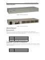
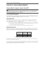
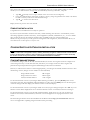
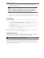
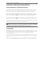
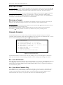
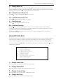
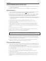
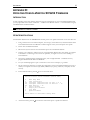
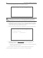
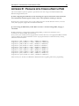
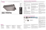
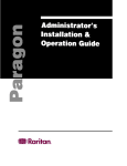
This page intentionally left blank
Copyright © 2002 Raritan Computer, Inc.
SCS232-0C
July 2002
Raritan Computer Inc.
400 Cottontail Lane
Somerset, NJ 08873
USA
Tel. 1-732-764-8886
Fax. 1-732-764-8887
E-mail: [email protected]
http://www.raritan.com
Raritan Computer Europe, B.V.
P.O. Box 566
2900 AN Capelle aan den IJssel
The Netherlands
Tel. 31-10-284-4040
Fax. 31-10-284-4049
E-mail: [email protected]
http://www.raritan.com
Raritan Computer Japan, Inc.
Kuga Building 7F
11-6, Kuramae 4-chome
Taitoo-ku, Tokyo 111-0051, Japan
Tel. 81-3-5833-6360
Fax. 81-3-5833-6336
E-mail: [email protected]
http://www.raritan.co.jp
Raritan Computer Taiwan, Inc.
5F, 121, Lane 235,
Pao-Chiao Rd., Hsin Tien
Taipei Hsien, Taiwan, ROC
Tel. 886-2-8919-1333
Fax. 886-2-8919-1338
E-mail: [email protected]
http://www.raritan.com.tw
This page intentionally left blank
FCC INFORMATION
This equipment has been tested and found to comply with the limits for a Class A digital device, pursuant to
Part 15 of the FCC Rules. These limits are designed to provide reasonable protection against harmful
interference in a commercial installation. This equipment generates, uses, and can radiate radio frequency
energy and if not installed and used in accordance with the instructions, may cause harmful interference to
radio communications. Operation of this equipment in a residential environment may cause harmful
interference.
Product names mentioned in this document are trademarks or registered trademarks of their respective
companies. Z-Series, Paragon, MasterConsole MX4, MasterConsole MXU2, MasterConsole II, MasterConsole
SMX, and their respective logos are registered trademarks of Raritan Computer, Inc. PS/2, RS/6000, and
PC/AT are registered trademarks of International Business Machines Corporation. Sun is a registered
trademark of Sun Microsystems. All other marks are the property of their respective owners.
JAPANESE APPROVALS
This page intentionally left blank
TABLE OF CONTENTS
CHAPTER 1: MANUAL NOTES ........................................................................................1
VERSION APPLICABILITY ........................................................................................................ 1
IMPORTANT NOTE: POWER RECYCLING ................................................................................. 1
CHAPTER 2: INTRODUCTION ..........................................................................................3
CONSOLESWITCH SCS232 FEATURES .................................................................................. 3
PACKAGE CONTENTS ............................................................................................................ 3
PRODUCT PHOTOS................................................................................................................ 4
RELATED PRODUCTS ............................................................................................................ 4
CHAPTER 3: CABLING REQUIREMENTS ..........................................................................5
CONSOLESWITCH CABLING: SERIAL OVER UTP..................................................................... 5
PARAGON CABLING: KVM OVER UTP ................................................................................... 6
CHAPTER 4: INSTALLATION ...........................................................................................7
CONSOLESWITCH STANDALONE INSTALLATION ...................................................................... 7
CONSOLESWITCH WITH PARAGON INSTALLATION ................................................................. 10
CHAPTER 5: OPERATING CONSOLESWITCH..................................................................15
PARAGON OPERATION: VIEWING STORED DATA................................................................... 15
HOTKEY MODE ................................................................................................................... 15
ACCESSING THE MAIN MENU ............................................................................................... 16
CHANNEL NAVIGATION ........................................................................................................ 16
CHANNEL SCANNING ........................................................................................................... 17
VIEWING STORED DATA ...................................................................................................... 18
APPENDICES ..............................................................................................................21
APPENDIX A: SPECIFICATIONS ...................................................................................21
APPENDIX B: PIN-OUT DIAGRAMS ..............................................................................22
APPENDIX C: UPDATING PARAGON FIRMWARE ............................................................24
APPENDIX D: UPDATING CONSOLESWITCH SCS232 FIRMWARE ...................................27
APPENDIX E: PARAGON WITH CONSOLESWITCH FAQ .................................................29
APPENDIX F: CONSOLESWITCH FAQ .........................................................................30
CHAPTER 1: MANUAL NOTES
CHAPTER 1: MANUAL NOTES
VERSION APPLICABILITY
Contents in this manual are applicable to ConsoleSwitch™ SCS232 firmware versions 0A2 and above.
Customers with 0A1 firmware should contact Raritan Technical Support for upgrade instructions.
IMPORTANT NOTE: POWER RECYCLING
ConsoleSwitch SCS232 contains special circuitry that prevents transmission of accidental “break” signals to
Sun Microsystems servers (and thereby causing them to go to bootprom mode) during ConsoleSwitch powerdown. This circuitry requires approximately three seconds to fully discharge, and ensure “break safety”.
Therefore,
IMPORTANT: To recycle power, turn ConsoleSwitch SCS232 off for
at least 5 seconds before restarting.
This allows ConsoleSwitch’s spurious “break” protection circuitry to fully discharge prior to restarting.
1
2
CONSOLESWITCH SCS232 USER’S MANUAL
CHAPTER 2: INTRODUCTION
3
CHAPTER 2: INTRODUCTION
CONSOLESWITCH SCS232 FEATURES
•
Dual user, simultaneous matrixed access to 32 serial devices
•
Compact 1U form factor
•
8kb data buffers for troubleshooting
•
Seamless integration with Raritan’s Paragon® data center management solution.
•
Platform and software independent
•
Channel-naming for convenient device access
PACKAGE CONTENTS
SCS232-RK (ConsoleSwitch with Rack Mount Brackets)
1
1
1
2
SCS232
n/a
n/a
CAT5-30
ConsoleSwitch Serial Switching
AC Power Cord
Set of 19” Rack Mount brackets
30’ Straight-through Cat 5 cable
2
2
2
2
ASCSDB25M
ASCSDB25F
ASCSDB9M
ASCSDB9F
RJ45(F) to DB25(M) nulling
RJ45(F) to DB25(F) nulling adapter
RJ45(F) to DB9(M) nulling adapter
RJ45(F) to DB9(F) nulling adapter
4
1
n/a
n/a
Self-adhesive plastic feet
Set of documentation
Main matrix-switching unit
AC power supply line to main unit
For optional Rack Mounting of main unit
Supplied for installation convenience; used for
connection of user consoles to ConsoleSwitch
For connection of user consoles*
For connection of user consoles*
For connection of user consoles*
For connection of user consoles*, and for
updating ConsoleSwitch firmware from a PC
To be used in non-Rack Mounted
Manual; Warrantee Information; etc.
*For your convenience, eight nulling adapters, two of each type, are provided for the purpose of connecting two
serial user consoles to ConsoleSwitch. Although you will need only two adapters to connect user consoles, save the
extras for convenience – these same adapters may be used to connect either consoles or devices to ConsoleSwitch.
SCS232-PKRK (ConsoleSwitch w/ Paragon-Ready Kit and Rack Mount Brackets)
1
1
1
2
SCS232
n/a
n/a
CAT5-007
ConsoleSwitch Serial Switching
Set 19” Rack Mount brackets
AC Power Cord
7’ Straight-through Cat5 cable
2
AUATC
Terminal emulator and KVM
converter
2
1
4
1
ASCSDB25M
ASCSDB9F
n/a
n/a
RJ45(F) to DB25(M) nulling
RJ45(F) to DB9(F) nulling adapter
Self-adhesive plastic feet
Set of documentation
Main matrix-switching unit
For optional Rack Mounting of main unit
AC power supply line to main unit
Supplied for installation convenience; used for
connection of ConsoleSwitch to AUATC
Emulates dumb terminal functionality to send
KVM signals to Paragon; enables seamless
integration between Paragon and
ConsoleSwitch
For connection of ConsoleSwitch to AUATC
For updating ConsoleSwitch firmware from a
To be used in non-Rack Mounted
Manual; Warranty Information; etc.
4
CONSOLESWITCH SCS232 USER’S MANUAL
PRODUCT PHOTOS
Figure 1. ConsoleSwitch SCS232 Front
Figure 2. ConsoleSwitch SCS232 Back
RELATED PRODUCTS
DEVICE ADAPTERS
Each serial device connected to ConsoleSwitch will require an RJ45 to DB9, or RJ45 to DB25, adapter.
Unfortunately, standard adapters do not exist for this application (serial over RJ45). Raritan supplies the following
adapters to meet your needs. Contact your Raritan reseller to order.
ASCSDB25M
ASCSDB25F
ASCSDB9M
ASCSDB9F
RJ45(F) to DB25(M) nulling serial adapter
RJ45(F) to DB25(F) nulling serial adapter
RJ45(F) to DB9(M) nulling serial adapter
RJ45(F) to DB9(F) nulling serial adapter
PARAGON MULTI-USER, MULTI-PLATFORM SWITCH
Raritan’s data center grade KVM switch provides network administrators with direct, out-of-band access to multiple
servers. ConsoleSwitch SCS232 integrates tightly with Paragon, allowing clustered access to serial devices through a
single, seamless interface.
UMT8
UST1
AUATC
8-user; 32-device matrix switch
User console station
Terminal Emulator and Converter
CHAPTER 3: INTRODUCTION REQUIREMENTS
5
CHAPTER 3: CABLING REQUIREMENTS
CONSOLESWITCH CABLING: SERIAL OVER UTP
NOTE: The following information applies only to cables that attach directly to the ConsoleSwitch unit. Cables
that attach to Raritan’s Paragon switches must meet stricter requirements; if you are using ConsoleSwitch in
tandem with Raritan’s Paragon data center management system, be sure to see the following section,
“Paragon Cabling: KVM Over UTP” for more information.
CAT 5 CABLE REQUIREMENTS
ConsoleSwitch allows easy, organized, and convenient connection to devices via standard UTP cable. Because
serial data requires relatively little bandwidth in comparison to Ethernet traffic, any standard, straight-through
UTP cable fastened with RJ45 modular plugs will suffice (Cat 5, Cat 5e, Cat 6).
DEVICE ADAPTERS
Each serial device and user console connected to ConsoleSwitch will require a nulling serial adapter. These
Raritan-supplied adapters will null ConsoleSwitch’s serial RJ45 connection, and adapt the physical plug to
match standard EIA-232 serial connectors (DB9 or DB25).
• To connect user consoles to ConsoleSwitch, use the adapters provided with your ConsoleSwitch unit.
• To connect devices to ConsoleSwtich, customers should order adapters appropriate for each device to
be connected (available from your Raritan reseller).
• Expert users may refer to Appendix B for ConsoleSwitch’s exact RJ45 serial pin-outs.
DISTANCE LIMITATIONS
While ConsoleSwitch does not itself impose cable distance limitations, all standard EIA-232 serial signals do.
Hence, devices connected to ConsoleSwitch should adhere to the following limitations specified in the EIA
standard. Longer cable lengths will result in signal degradation and therefore, cause functional errors to occur:
Data Rate
(baud)
2400
4800
9600-38400
Distance
(Feet)
200
100
50
Distance
(Meters)
60
30
15
Figure 3. EIA-232 Standard Speed / Distance Limitations
User consoles (dumb terminals, terminal emulators, etc.) connected to the user ports of ConsoleSwitch must
also adhere to the same distance limitations.
It is worth noting that the EIA created RS-232 cabling specifications many decades ago. In practice, using high
quality, shielded cable can yield much longer, successful cabling distances without data loss. However, Raritan
can only guarantee operation quality at the EIA specification.
6
CONSOLESWITCH SCS232 USER’S MANUAL
PARAGON CABLING: KVM OVER UTP
NOTE: The following information addresses the stricter cabling requirements of Raritan’s Paragon switches.
These specifications are more stringent than for ConsoleSwitch. If you are using ConsoleSwitch as a
standalone serial access device, you may ignore this section.
CERTIFIED CABLE
Raritan certifies the following Category 5e UTP and Category 6 UTP cable products for use with Paragon:
Certified Cables for Use with Raritan Products
Category 5e UTP Cable:
Category 6 UTP Cable:
Belden DataTwist 350 UTP
Belden DataTwist 350 patch
Belden MediaTwist
#1700A
#1752A
#1872A
Solid
Stranded
Solid
Use of non-certified cabling can result in video and data degradations that users may find unsatisfactory.
Certified Raritan cable products listed above are widely available and competitively priced. When using certified
cable, users can transmit video signals at distances up to 1,000 feet at 1024x768 @75Hz; and up to 600 feet at
1600x1200 @75Hz.
NOTE: Raritan does not have any marketing relationship with Belden, nor does Raritan receive any financial
incentive for recommending Belden products.
For more information, please see your Paragon Manual.
CHAPTER 4: INSTALLATION
7
CHAPTER 4: INSTALLATION
CONSOLESWITCH STANDALONE INSTALLATION
NOTE: The following information applies to configurations in which ConsoleSwitch is used as a standalone serial
access device. Users intending to use ConsoleSwitch in a Paragon solution should skip to the section entitled
“ConsoleSwitch with Paragon Installation.”
PREPARATION
In order to operate ConsoleSwitch SCS232, you will need at least one dumb terminal (e.g., DEC VT100) or terminal
emulator (e.g., laptop, e.g., Raritan AUATC Terminal Emulator and Converter) to access and control connected
devices. In this manual, dumb terminals or terminal emulators used to operate ConsoleSwitch are called “user
consoles”.
By default, ConsoleSwitch expects each user console to be set at the following parameters. These settings may be
changed later; however, in order to perform initial setup, at least one user console must be set to these parameters.
Enter/Return Key:
Baud Rate:
Data Bits:
Stop Bits:
Parity:
Software/Hardware Handshaking:
CR (carriage return)
9600
8
1
None
None
By default, ConsoleSwitch expects attached devices to be set with the following communications parameters. At this
time, make a note of any devices that vary from these settings; their corresponding ConsoleSwitch device ports will
have to be configured later.
Baud Rate:
Data Bits:
Stop Bits:
Parity:
9600
8
1
None
Last, ensure that all devices to be controlled via ConsoleSwitch are set to the same terminal emulation as that of
your user consoles.
8
CONSOLESWITCH SCS232 USER’S MANUAL
CONNECTING USER CONSOLES
1.
2.
3.
In your ConsoleSwitch shipment (see Chapter 2: Introduction - Package Contents), you will find an
assortment of nulling serial adapters (RJ45 to DB9 / DB-25).
Locate the RS232 (serial) port on each device that you wish to use as a user console. Select a nulling serial
adapter that fits the gender and form-factor of each device’s serial port, and attach them.
Using standard, straight-through UTP cable no longer than 50 feet in length (see Chapter 3: Cabling
Requirements - ConsoleSwitch Cabling), connect each user console to either of the User Ports on the back
of ConsoleSwitch.
Figure 4. User Console Cabling to ConsoleSwitch
CONNECTING SERIAL DEVICES
1.
2.
For each device that you wish to control via ConsoleSwitch, connect an appropriate Raritan-supplied
nulling serial adapter (See Chapter 2: Introduction - Related Products) that fits the gender and form factor
of the device’s serial console port – sometimes labeled “Admin”, “COM”, “Serial”, “RS232”, or “AUX”.
Using standard, straight-through UTP cable of an appropriate length (see Chapter 3: Cabling
Requirements - ConsoleSwitch Cabling), connect each nulling serial adapter to a Device Port (labeled 1
through 32) on the back of ConsoleSwitch.
Figure 5. Device Cabling to ConsoleSwitch
CHAPTER 4: INSTALLATION
9
POWER ON
1.
2.
3.
With your user consoles and devices attached, connect the supplied AC power cord to ConsoleSwitch, and
switch the power on. Note that terminals and devices may be attached or disconnected at any time.
On the bottom-left of your user console, you will see a message directing you to type H ↵ to access the
main help menu. (Note: if you attach a user console after ConsoleSwitch has already been powered on, you
will not see this message). Type H ↵ to access the main menu, entitled “Raritan ConsoleSwitch
Commands”.
The following menu will be displayed:
Raritan Console Switch Commands (SCS232 v0A2)
H
V
U#
D#
N#
C
D
S
F
Main Help Menu
View Stored Data
Configure Communications for User 1 or 2
Configure Communications for Device 1 - 32
Name Device 1 - 32
Select Channel
Display All Channels
Scan Menu
Update Firmware
Press CTRL+G to Enter/Exit HotKey Mode
Figure 6. Main Menu
CONFIGURING CHANNEL NAMES AND SETTINGS
For each channel to which you have attached a device, perform the following actions:
1.
2.
3.
Type N# ↵ (where # is the channel number of the attached device). Assign an appropriate name to the
device connected to that channel (e.g. “WWW1-NETRAT1”), and press ↵. Channel names may be up to
12 characters in length; they are stored in non-volatile memory, and will therefore be maintained even if
ConsoleSwitch is powered off.
If the device is set to 9600 Baud, No Parity, 8 Data Bits, 1 Stop Bit; then you are finished configuring the
channel; proceed to the next device.
If the device is not set to 9600 Baud, No Parity, 8 Data Bits, 1 Stop Bit; then type D# ↵ (where # is the
channel number of the attached device) to enter the communications setting menu. Using the menu,
change any parameter that needs to be altered in order to match your device’s communication settings.
Communication Setup:
B
W
P
S
F
R
Set Baud Rate
Set Word Length (No. of Data Bits)
Set Parity
Set No. of Stop Bits
Set Flow Control
Reset all Settings to Default Values
Defaults: 9600 Baud, 8 Data Bits, No Parity, 1 Stop
Bit.
H
Exit to Main Menu
Figure 7. Communications Setup Menu
It is important to realize that configuring these communications settings affects ConsoleSwitch’s device
port only, not the external device. ConsoleSwitch communications settings should be changed to match
the settings of connected terminals and devices.
4.
Type H ↵ to return to the main menu.
After configuring each device channel port, proceed to the next section.
CONFIGURING USER CONSOLE COMMUNICATIONS SETTINGS
10
CONSOLESWITCH SCS232 USER’S MANUAL
This section only applies if you wish to operate ConsoleSwitch with a user console (dumb terminal or terminal
emulator) set to communications settings other than 9600 Baud, No Parity, 8 Data Bits, 1 Stop Bit.
1.
2.
3.
Type U# ↵ (where # is the user port number of the user console to be configured).
Using the communications setup menu (see Figure 7 above), change any parameter that needs to be altered
in order to match your device’s communication settings.
Type H ↵ to return to the main menu.
Repeat, if necessary, for the other user channel.
COMPLETING INSTALLATION
Congratulations! ConsoleSwitch is now ready for operation.
If you have any free channels in the back of the unit, consider attaching other devices to ConsoleSwitch, such as
networking equipment (switches and routers), network appliances (firewalls, load balancers, etc.), or servers. While
many of these devices may be managed via Telnet, Web, or SNMP; in the case of network failure, the
admin/console ports may be your only option for management and configuration, and ConsoleSwitch allows you
convenient access to those ports at a very low cost.
CONSOLESWITCH WITH PARAGON INSTALLATION
NOTE: The following information applies to configurations in which ConsoleSwitch is used as an add-on to a
Pargaon™ data center management solution, enabling seamlessly integrated, clustered access to serial devices
from the familiar Paragon interface. Users intending to use ConsoleSwitch in a standalone solution should skip
this section and refer to the previous section “ConsoleSwitch Standalone Installation”.
CONFIRM FIRMWARE VERSION
ConsoleSwitch, Paragon, and the AUATC Terminal Emulator/Converter auto-negotiate and auto-configure most
of the settings necessary to work with each other; this allows you to simply connect the devices together and
perform all setup and operations through the familiar Paragon On-Screen User Interface.
However, in order for these features to function appropriately, your Paragon and AUATC firmware must be at least
the following versions (Paragon version numbers are in hexadecimal):
Paragon Matrix Switch:
Paragon UST1 user station:
AUATC terminal emulator:
2B0 or higher
2K0 or higher
v2.54 or higher
To check the firmware version of your Paragon Matrix Switch (p/n UMTxx), press the [FUNC] button on the
front panel of the unit. The LCD display will read “Display Ver./SN”. Press the [ENT] button on the front panel
of the unit. Paragon will then display your firmware version on the LCD display.
To check the firmware version of your Paragon UST1 user stations, login to Paragon and press the <F8> key. Your
firmware version will be displayed. Be sure to check the firmware version of each UST1 connected to Paragon.
To check the firmware version of your AUATC terminal emulator, simply power on your unit. If a monitor is
attached to the AUATC terminal emulator, a firmware version will appear on the top right-hand corner of the
screen.
The latest Paragon firmware can be downloaded from the Raritan website http://www.raritan.com. Please be
sure to read Appendix C: Updating Paragon Firmware before proceeding.
CHAPTER 4: INSTALLATION
11
PREPARE DEVICES
Devices to be controlled by Paragon through ConsoleSwitch must be set at the following communications settings.
Before proceeding, check all devices that you wish to connect, and ensure that they have been set correctly. Consult
your device’s user manual to change the communications parameters if they do not match.
Terminal Emulation:
Baud Rate:
Data Bits:
Stop Bits:
Parity:
VT100
9600
8
1
None
CONNECTING SERIAL DEVICES
1.
2.
For each device that you wish to control via ConsoleSwitch, connect an appropriate Raritan-supplied
nulling serial adapter (See Chapter 2: Introduction - Related Products) that fits the gender and form factor
of the device’s serial console port – sometimes labeled “Admin”, “COM”, “Serial”, “RS232”, or “AUX”.
Using standard, straight-through UTP cable of an appropriate length (see Chapter 3: Cabling
Requirements - ConsoleSwitch Cabling), connect each nulling serial adapter to a Device Port (labeled 1
through 32) on the back of ConsoleSwitch.
See Figure 5: Device Cabling to ConsoleSwitch (in previous section) for clarification.
12
CONSOLESWITCH SCS232 USER’S MANUAL
CONNECTING CONSOLESWITCH TO PARAGON
All cabling performed in the following steps must conform to the requirements specified in Chapter 3: Cabling
Requirements -Paragon Cabling – KVM over UTP.
1.
In your ConsoleSwitch shipment (see Chapter 2: Introduction - Package Contents), you will find two
nulling serial adapters (RJ45 to DB-25), Raritan part number SCSDB25M; and two terminal emulator
/converters, Raritan part number AUATC. Connect each nulling serial adapter to the two AUATC
terminal emulators, in the port labeled “To ASCII Terminal Port.” Secure the adapter with the
thumbscrews.
2.
Using the supplied 7’ straight-through Category 5e UTP cables (or any other straight-through UTP cable
shorter than 50 feet in length), connect each ConsoleSwitch user port to the two AUATC emulators. One
end of the UTP cable should be inserted into the ConsoleSwitch ports labeled “User 1” and “User 2”; the
other end of the UTP cable should be inserted into the nulling serial adapter that you attached to AUATC
in the previous step. See Figure 8 for an illustration of the final connection.
3.
Using Category 5e UTP cable, connect the AUATCs to two device ports of your Paragon switching unit
(P/N UMT8). No adapters are necessary; simply insert one end of the cable into an AUATC’s “UTP
Cable” port, and the other end into the Paragon device port. With the appropriate cable, the combined
cable distance from AUATC to any Paragon user station may total up to 1000 feet.
Figure 8. Paragon Cabling to ConsoleSwitch
POWER ON
1.
Plug each supplied 6V DC power supply provided with the AUATCs into the two terminal emulators.
2.
After first ensuring that the power switch is in the “off” position, connect the provided AC power cord to
ConsoleSwitch SCS232, and plug into an appropriate power source.
3.
With your serial devices attached and powered on, toggle the power switch to turn on ConsoleSwitch
SCS232.
ADMINISTRATIVE SETUP
1.
Immediately after ConsoleSwitch SCS232 is powered on, the Paragon On-Screen User Interface should
indicate that the Paragon database is updating.
CHAPTER 4: INSTALLATION
2.
13
When the update is complete, login as “admin” (default password is “raritan”). Channel numbers
corresponding to Paragon device ports connected to ConsoleSwitch SCS232 should appear in burgundy
(each is a “path” to the SCS232).
NOTE: If channel numbers corresponding to device ports connected to ConsoleSwitch SCS232 appear
green instead of burgundy, press <F5> and select “Channel Configuration” from the On-Screen User
Interface. Use the <↑> and <↓> arrow keys to select a channel connected to ConsoleSwitch. Press
<TAB> to move to the “Device” column corresponding to that channel, and press <ENTER>. Use the
arrow keys to find “SCS232”. Press <ENTER> and then <S> to save. Press <F2> to activate the
Selection Menu. All paths to ConsoleSwitch SCS232 should now appear in burgundy.
3.
Press <F5> to enter to the Administration Menu. Select “Channel Configuration”.
4.
Move the cursor to one of the two channels to which ConsoleSwitch SCS232 is connected. Press <G> to
invoke a Channel Configuration menu for ConsoleSwitch SCS232-connected devices. Proceed to the next
section.
CHANNEL NAMING
From the “Channel Configuration” menu for SCS232, you may now name all devices that are connected to
ConsoleSwitch, as follows:
1.
Press <TAB> to move the cursor to the “Name” column of a ConsoleSwitch channel that you wish to
name, then press <ENTER> to highlight the parameter (cursor will turn blue).
2.
Assign the device a meaningful name of your choice (e.g., “WWW1-NETRAT1”). Channel names may be
up to 12 characters in length.
3.
Press <ENTER> to save the change. Channel names are stored in non-volatile memory, and will
therefore be maintained even if ConsoleSwitch or Paragon is powered off.
4.
Press <S> to save the new channel configuration.
Repeat the steps to name all devices connected to ConsoleSwitch, and press <F2> to invoke Paragon’s channel
Selection Menu. All name changes should now appear in Paragon’s OSUI.
COMPLETING INSTALLATION
Congratulations! ConsoleSwitch is now ready for operation via Paragon. All Paragon features such as security
groups, channel scanning, and remote access via TeleReach™ apply to – and work seamlessly – with the serial
devices you have connected to ConsoleSwitch. See your Paragon manual for more details.
NOTE: Although up to eight users may be using Paragon simultaneously, no more than two users can have
simultaneous access to devices connected to your ConsoleSwitch unit.
If you have any free channels in the back of ConsoleSwitch, consider attaching other devices such as networking
equipment (switches and routers), network appliances (firewalls, load balancers, etc.), or servers for true “lights-out”
network operations. While many of these devices may be managed via Telnet, Web, or SNMP; in the case of
network failure, the admin/console ports may be your only option for management and configuration, and Paragon
enables you convenient access to those ports.
14
CONSOLESWITCH SCS232 USER’S MANUAL
CHAPTER 5: OPERATING CONSOLESWITCH
15
CHAPTER 5: OPERATING CONSOLESWITCH
PARAGON OPERATION: VIEWING STORED DATA
When using ConsoleSwitch in tandem with Raritan’s Paragon server management solution, users access and
operate serial devices connected to ConsoleSwitch via Paragon’s menus and functions. Channel switching,
naming, security, and other operating procedures of Paragon all apply seamlessly to ConsoleSwitch.
However, ConsoleSwitch provides one additional powerful feature to your Paragon system: for each serial
device connected to Paragon via ConsoleSwitch, users may view a history (buffer) of that device’s most recent
activity. To do so, simply press <CTRL+G> at any time while connected to a ConsoleSwitch serial device.
In the menu that appears, press V ↵ to access ConsoleSwitch’s “View Stored Data” feature. When you have
finished viewing stored data, press <CTRL+G> to resume normal operation (quit “View Stored Data” mode).
For all other operating procedures when using ConsoleSwitch in a Paragon configuration, consult your Paragon
manual. Also be sure to see Appendix E: Paragon / ConsoleSwitch FAQ.
NOTE: The remaining information in this section only applies to ConsoleSwitch in a standalone operation
(not using Raritan’s Paragon system). Users employing ConsoleSwitch in a Paragon solution may disregard
the remainder of this section. Paragon users access and operate serial devices connected to ConsoleSwitch
via Paragon’s menus and functions. See the Paragon manual for operating instructions.
HOTKEY MODE
ConsoleSwitch enables users to directly access connected devices in a completely transparent way. Users may
interact with connected devices as if ConsoleSwitch were not involved in the signal path. However, users must
access ConsoleSwitch menus in order to perform actions such as switching channels, configuring
communication protocols, etc.
When users are interacting with ConsoleSwitch menus, this is called “HotKey Mode.” In contrast, when users
are interacting directly with connected devices (not the ConsoleSwitch menus), they are outside of “HotKey
mode”.
At any time while using ConsoleSwitch, users may press <CTRL+G> to enter and exit HotKey mode.
16
CONSOLESWITCH SCS232 USER’S MANUAL
ACCESSING THE MAIN MENU
•
•
At any time while in HotKey mode, you may invoke the main menu by pressing H ↵.
When interacting directly with a connected device, press the <ESC> key twice to enter HotKey
mode, and the main menu will appear.
Raritan Console Switch Commands (SCS232 v0A2)
H
V
U#
D#
N#
C
D
S
F
Main Help Menu
View Stored Data
Configure Communications for User 1 or 2
Configure Communications for Device 1 - 32
Name Device 1 - 32
Select Channel
Display All Channels
Scan Menu
Update Firmware
Press CTRL+G to Enter/Exit HotKey Mode
Figure 9. Main Menu
CHANNEL NAVIGATION
DISPLAY CHANNELS
From the main menu, simply enter the keystrokes D ↵ to display a list of device channels. A screen
resembling the following will appear:
CH
NAME
STATUS
1
2
3
4
5
6
7
8
9
10
11
12
13
14
15
16
ROUTER-T3-1
ROUTER-T3-2
ROUTER-T3-3
WWW1-NETRAT1
WWW2-NETRAT2
WWW3-NETRAT3
*
1
*
*
*
CRM-APPSVR1
CRM-APPSVR2
*
*
SCAN
CH
NAME
*
*
*
*
*
*
*
*
*
*
*
*
*
*
*
*
17
18
19
20
21
22
23
24
25
26
27
28
29
30
31
32
DB2-RS6000-1
DB2-RS6000-1
STATUS
Press Enter to Refresh, H for Help Display
Figure 10. Channel Selection / Display
The status column indicates device status:
*
1 or 2
[blank]
Device attached to this channel is active, and channel is available
Channel is occupied by User 1 (1); or User 2 (2);
Device attached to this channel is not active
*
2
SCAN
*
*
*
*
*
*
*
*
*
*
*
*
*
*
*
*
CHAPTER 5: OPERATING CONSOLESWITCH
17
SELECTING A CHANNEL
By Channel Number. To select a channel by number from the main menu, simply enter the keystrokes C# ↵,
where # is a number between 1 and 32, indicating the ConsoleSwitch port to which the desired serial device is
connected. You will immediately exit HotKey mode and be directly connected to the selected channel.
From Channel Selection Menu. To select a channel by name, simply enter the keystrokes C ↵. ConsoleSwitch
will display a list of all channels (see Figure 10), and prompt you to select a channel by number. When
prompted, enter the channel number of the device to which you would like to connect. You will immediately
exit HotKey mode and be directly connected to the selected channel.
RELEASING A CHANNEL
When one user accesses a device on ConsoleSwitch, that channel cannot be accessed by the other user port.
Therefore, when finished operating a device, be sure to release access to the channel as follows:
By Channel Number. From the main menu, simply enter the keystrokes C0 ↵. Selecting channel zero releases
any channel access you may currently possess.
From Channel Selection Menu. From the Channel selection menu, select channel zero by entering the
keystrokes 0 ↵. Selecting channel zero releases any channel access you may currently possess.
CHANNEL SCANNING
ConsoleSwitch allows users to monitor activity on all ConsoleSwitch channels through use of the Scan
commands, which perpetually switches through and displays every channel at a user-defined interval. To access
the list of channel scanning commands, press S ↵ from the main menu.
Scan Command Menu
S#:
A#:
K#:
L#:
C:
R#:
D:
H:
Scan All Channels (# = 1 to 99 secs)
Scan Active Channels (# = 1 to 99 secs)
Skip Channel in Scan List (# = channel 1 thru 32)
Add Channel to Scan List
Clear Scan List
Resume Scanning (# = 1 to 99 secs)
Display Scan List
Quit Scan Mode/Restore Main Menu
Figure 11. Channel Scanning Menu
ConsoleSwitch maintains a “Scan List” for each user, enabling you to only scan through those channels in
which you are interested. Use the following commands to invoke scanning and to manage your scan list.
S# — Scan All Channels
Enter S# ↵ from the Channel Scanning menu to add all channels to your scan list, and immediately commence
scanning through channels at an interval of # seconds per channel. During scanning, the number of the
channel being viewed will be displayed on the attached terminal. Press any key to stop the scan and return to
the Channel Scanning Menu.
A# — Scan Active Channels Only
Enter A# ↵ from the Channel Scanning to add all active channels to set your scan list to include only those
channels that are active, and immediately commence scanning through those channels at an interval of #
seconds per channel. During scanning, the number of the channel being viewed will be displayed on the
attached terminal. Press any key to stop the scan and return to the Channel Scanning Menu.
18
CONSOLESWITCH SCS232 USER’S MANUAL
D — Display Scan List
To see a list of all channels on your scan list, press D ↵. This screen is identical to the channel selection and
display screen referenced earlier in this manual (Figure 10). From this screen, you may still invoke any Channel
Scanning command, or press S ↵ to redisplay the Channel Scanning menu.
K# — Skip Channel in Scan List
Press K# ↵ to remove channel number # from your scan list.
L# — Add Channel to Scan List
Press L# ↵ to add channel number # to your scan list.
C — Clear Scan List
Press C ↵ to clear all channels from your scan list.
R# — Resume Scanning
Press R# ↵ to resume scanning through your scan list at an interval of # seconds per channel. During
scanning, the number of the channel being viewed will be displayed on the attached terminal. Press any key to
stop the scan and return to the Channel Scanning Menu.
You may use the R# ↵ command to alter your scan rate, or simply enter R ↵ to resume scanning at the
previous (or default) rate.
VIEWING STORED DATA
ConsoleSwitch allows users to troubleshoot problems with attached devices by storing and making available the
latest activity that occurred on each port connected to ConsoleSwitch. To view stored data, you must first
select a channel (see previous section, “Channel Navigation”), and the latest page of data will be displayed.
To see more data, press <CTRL+G> to enter HotKey mode. Then, from the main menu, press V ↵ to access
additional scan commands.
View Commands Menu
L
O
P
N
F#
R#
P#
Y#
H
Display Latest Data
Display Oldest Data
Display Previous Page
Display Next Page
Forward # Lines
Reverse # Lines
Set Page Length to # Lines
Clear Channel # Data
Exit to Main Menu
Figure 12. View Stored Data Menu
L — Display Latest Data
Moves the screen to the most recent full screen of stored data.
O — Display Oldest Data
Moves the screen to the oldest full screen of information stored.
P — Display Previous Page
Moves the display to the previous screen of information stored.
N — Display Next Page
Moves the display to the next screen of information stored.
CHAPTER 5: OPERATING CONSOLESWITCH
19
F# — Forward # Lines
Moves the display cursor a user-determined number of lines forward to a new screen starting point, # number
of lines forward.
R# — Reverse # Lines
Moves the display cursor a user-determined number of lines backward to a new screen starting point, # number
of lines backward.
P# — Set Page Length to # Lines
Determines the number of available lines in a display, where ## = number of lines to be displayed. To set the
page length, subtract one line from the total available number of lines on your display. The last line at the
bottom of the screen is reserved for the SCS command prompt. The default value is set at 23.
Y# — Clear Channel # Data
The Y command is used when the user wishes to clear the entire queue (memory) for a specified channel. This
command might be used when the user wishes to start the queue over if the attached devices were reconfigured.
NOTE: Memory is organized in such a way that once the 32K of memory is full, the new data is written over
the oldest data. This ensures that only the newest 32K of data is stored. Because of this feature, it is not
necessary to clear the queue when it is full.
20
CONSOLESWITCH SCS232 USER’S MANUAL
APPENDICES
21
APPENDICES
APPENDIX A: SPECIFICATIONS
DIMENSIONS
17.3” (W) X 6.4” (D) X 1.75” (H)
439MM (W) X 163MM (D) X 44MM (H)
1U FORM FACTOR
WEIGHT
5.5 LBS (2.5 KG)
POWER
100V/240V (AUTO-DETECT)
50/60 HZ 5VA
PORTS
32
PROTOCOL
RS232
CONNECTORS
RJ45
DATA BUFFER
10 MEGABIT (SHARED)
22
CONSOLESWITCH SCS232 USER’S MANUAL
APPENDIX B: PIN-OUT DIAGRAMS
In order to provide maximum port density and to enable simple UTP (Category 5) cabling, ConsoleSwitch
provides its 32 serial connections via compact RJ45 ports. However, no widely adopted industry-standard exists
for sending serial data over RJ45 connections. For your reference, the serial pin-out employed by
ConsoleSwitch is provided below.
CONSOLESWITCH RJ45 SERIAL PIN-OUT
RJ45 (Female)
1
2
3
4
5
6
7
8
Function
RTS
DTR
TXD
GND
SG
RXD
DSR
CTS
SCSDB25F NULLING SERIAL ADAPTER PIN-OUT
RJ45 (Female)
1
2
3
4
5
6
7
8
DB25 (Female)
5
6, 8
3
1
7
2
20
4
SCSDB25M NULLING SERIAL ADAPTER PIN-OUT
RJ45 (Female)
1
2
3
4
5
6
7
8
DB25 (Male)
5
6, 8
3
1
7
2
20
4
APPENDICES
23
SCSDB9F NULLING SERIAL ADAPTER PIN-OUT
RJ45 (Female)
1
2
3
4
5
6
7
8
DB9 (Female)
8
1, 6
2
SHELL
5
3
4
7
SCSDB9M NULLING SERIAL ADAPTER PIN-OUT
RJ45 (Female)
1
2
3
4
5
6
7
8
DB9 (Male)
8
1, 6
2
SHELL
5
3
4
7
CUSTOM, NULLING RJ45 CABLE (FOR MOST SUN AND CISCO RJ45
DEVICES)
Like ConsoleSwitch, many newer devices also provide serial ports in RJ45 form. However, as noted above,
each implementation is proprietary: not all serial ports using RJ45 connectors are alike!
Owners of hardware with RJ45 serial ports, who very familiar with network cabling, may be able to crimp their
own UTP/Cat 5 cable such that no adapters are necessary to connect their device to ConsoleSwitch; a single,
custom-made UTP/Cat 5 cable can connect the device’s RJ45 serial port to ConsoleSwitch’s RJ45 serial device
ports.
To do so, reference the RJ45 pin-out diagram above, along with the serial RJ45 pin-out diagram of your device.
For your convenience, the following cable pin-out diagram can be used to make a UTP / Cat 5 cable that
connects ConsoleSwitch to most Sun and Cisco devices equipped with RJ45 serial ports, such as the Sun Netra
T1 server.
RJ45 (Male)
1
2
3
4
5
6
7
8
RJ45 (Male)
8
7
6
5
4
3
2
1
WARNING: Not all Sun and Cisco devices have been
tested with this cable; you must refer to the user’s manual
of your device, to confirm its pin-out. If you are at all
unfamiliar with this procedure, you should not attempt to
make your own direct-connect cable – instead, use
Raritan’s standard DB9 and DB25 adapters.
24
CONSOLESWITCH SCS232 USER’S MANUAL
APPENDIX C: UPDATING PARAGON FIRMWARE
NOTE: This Appendix does not apply to users deploying ConsoleSwitch as a standalone serial switching
device. This Appendix applies only to users deploying ConsoleSwitch with Raritan’s Paragon™ data center
management solution. Refer to Chapter 4: Installation - ConsoleSwitch with Paragon Installation for
instructions to determine whether you require a Paragon firmware update.
INTRODUCTION
To take advantage of the latest features and ensure the best performance of your Paragon system, you may
upload the newest levels of firmware onto each component of your Paragon environment.
The Paragon Update Utility is a Win32-based program that facilitates the transfer of firmware to your Paragon
units. Both Paragon Update, as well as the latest versions of firmware, can be downloaded from Raritan’s web
site at http://www.raritan.com.
NOTE: Before performing a firmware upgrade, be certain to read the release notes that are included with the
firmware distribution on Raritan’s website.
NOTE: In order to perform a firmware update, you do not need to power down any of the servers and devices
connected to Paragon. Because of Paragon’s modular and redundant design these devices will not be
affected at all during the update process.
PARAGON CONFIGURATION BACKUP INSTRUCTIONS
Paragon Update is designed to execute the firmware uploading process without disturbing your Paragon
configuration data files. However, as a precaution, many users prefer to backup these configuration files –
which contain user profile and server name information – as an added precaution. This step is not a
requirement, but simply a precaution.
If you would like to backup your Paragon Configuration files, download the Paragon OverView program
available from Raritan’s web site, at http://www.raritan.com:
1.
Download the Paragon OverView program available at the Raritan web site:
http://www.raritan.com.
2.
On any active Paragon User Station (p/n UST1), log into Paragon, and press <F12 >to bring the onscreen user display to “Selection Menu by Name” (and not simply, “Selection Menu”).
3.
With the Paragon User Station displaying “Selection Menu by Name”, connect one end of a straightthrough serial cable to the port labeled “Admin” on the back of the User Station (DB9F). Connect
the other end of the cable to the serial port of any computer with Paragon OverView installed.
To ensure reliable communication, you should use as short a serial cable as is convenient. Do not use
a serial cable longer than 50 feet in length. Make sure you are using a straight-through serial cable, and
not a null modem cable.
4.
On the attached computer, launch Paragon OverView by double-clicking on the icon.
5.
Select the correct serial port (COM1 through COM4), and click “Activate Port” to initiate
communication with Paragon.
6.
After the Paragon database is downloaded, you will be prompted for an administrator’s username and
password.
7.
Select Save from the File menu, and save the Paragon Configuration database to your hard disk.
8.
Select Exit from the File menu to exit the Paragon OverView program.
APPENDICES
25
PARAGON FIRMWARE UPDATE INSTRUCTIONS
1.
Download the Paragon Firmware distribution file (ParagonFirmware.zip), available at the Raritan web
site: http://www.raritan.com.
2.
Unzip the downloaded file, and read the release notes for any additional or updated instructions.
Update User Stations
1.
On any active Paragon User Station (p/n UST1), log into Paragon, and press <F12> to bring the onscreen user display to “Selection Menu by Name” (and not simply, “Selection Menu”).
2.
With the Paragon User Station displaying “Selection Menu by Name”, connect one end of a straightthrough serial cable to the port labeled “Admin” on the back of the User Station (DB9F). Connect
the other end of the cable to the serial port of any computer with Paragon Update installed.
To ensure reliable communication, you should use as short a serial cable as is convenient. Do not use
a serial cable longer than 50 feet in length. Make sure you are using a straight-through serial cable, and
not a null modem cable.
3.
On the attached computer, launch Paragon Update by double-clicking on the icon.
4.
Select the correct serial port (COM1 through COM4), and click “Activate Port” to initiate
communication with Paragon.
5.
Click “Load Hex File” and select the User Station firmware contained in the Paragon Firmware
distribution file (e.g. “UST1-####”, where #### is a hexadecimal version number). The first
button found in the “Upgrade Information” section of the window should change to “Paragon User
Station”.
6.
Click “Test Hex File” to ensure file integrity.
7.
Click “Check Device Information” to confirm successful communication with the Paragon User
Station, as well as to confirm that the firmware upgrade is applicable.
8.
Click “Paragon User Station” to begin uploading the firmware.
Warning: During the firmware uploading process, it is absolutely essential that neither the User
Station nor the computer is turned off; and that the serial cable remains firmly connected.
9.
Click “Disable Port”, and exit Paragon Update.
10. After successfully receiving the new firmware, the User Station should reset automatically, and you
will hear a beep to indicate the reset. If not, then reset power to the User Station manually. (Resetting
power to the user station will not cause any data loss).
11. Repeat steps 1 through 11 for each User Station. For the most reliable results, you should click
“Disable Port” and exit Paragon Update after updating each User Station.
Update Paragon Matrix Switch(es)
1.
Connect one end of a straight-through serial cable to the port labeled “Admin” (DB9F) on the back
of your Paragon Matrix Switch (p/n UMT8) to be updated. Connect the other end of the cable to the
serial port of any computer with Paragon Update installed.
To ensure reliable communication, you should use as short a serial cable as is convenient. Do not use
a serial cable longer than 50 feet in length. Make sure you are using a straight-through serial cable, and
not a null modem cable.
2.
On the attached computer, launch Paragon Update by double-clicking the icon.
3.
Select the correct serial port (COM1 through COM4), and click “Activate Port” to initiate
communication with Paragon.
4.
Click “Load Hex File” and select the Matrix Switch firmware contained in the Paragon Firmware
distribution file (e.g., “UMT8-####”, where #### is a hexadecimal version number). The first
button found in the “Upgrade Information” section of the window should change to “Send to
Paragon.”
26
CONSOLESWITCH SCS232 USER’S MANUAL
5.
Click the “Test Hex File” button to ensure file integrity.
6.
Click “Check Device Information” to confirm successful communication with the Paragon Matrix
Switch, as well as to confirm that the firmware upgrade is applicable.
7.
Click “Send to Paragon” to begin uploading the firmware.
Warning: During the firmware uploading process, it is absolutely essential that neither the Matrix
Switch (UMT8) nor the computer is turned off; and that the serial cable remains firmly connected.
8.
Click “Disable Port”, and exit Paragon Update.
9.
Using the power switch located at the back of your unit, recycle power to your Paragon Matrix
Switch. Upon resetting, the front LCD screen should display the latest firmware version number.
10. Repeat steps 1 through 10 for each Matrix Switch in your system. For the most reliable results, you
should click on “Disable Port” and exit Paragon Update after updating each Matrix Switch (UMT8).
APPENDICES
27
APPENDIX D:
UPDATING CONSOLESWITCH SCS232 FIRMWARE
INTRODUCTION
To take advantage of the latest features and ensure the best performance of your ConsoleSwitch SCS232 unit,
you may upload the newest levels of firmware – available on the Raritan web site – to ConsoleSwitch using any
standard Windows terminal emulator.
NOTE: Before performing a firmware upgrade, be certain to read the release notes that are included with the
firmware distribution on Raritan’s website!
UPDATE INSTRUCTIONS
ConsoleSwitch SCS232 uses the XMODEM file transfer protocol to update its firmware via the User Port #1:
1.
Using a web browser on a Win32 computer, access http://www.raritan.com, and download the latest
ConsoleSwitch firmware from Raritan’s technical support section, and uncompress the .zip file.
2.
Power off ConsoleSwitch SCS232.
3.
Disconnect any active devices from the channel ports of ConsoleSwitch SCS232.
4.
Connect your computer to either User Port of ConsoleSwitch SCS232. For more details, see Chapter
4: Installation - Connecting User Consoles. In particular, see Figure 4 “User Console Cabling to
ConsoleSwitch”
5.
Launch any standard windows terminal program, such as HyperTerminal - a standard accessory
program distributed with Microsoft Windows.
6.
Use your terminal program to open a connection to the correct serial port, e.g. COM1.
7.
Set the connection parameters to match the configuration of the ConsoleSwitch SCS232 user port to
which your computer is connected (by default, 9600 baud, no parity, 8 data bits, 1 Stop Bit, no flow
control).
8.
In the terminal window, press H ↵ to access the main menu.
Raritan Console Switch Commands (SCS232 v0A2)
H
V
U#
D#
N#
C
D
S
F
Main Help Menu
View Stored Data
Configure Communications for User 1 or 2
Configure Communications for Device 1 - 32
Name Device 1 - 32
Select Channel
Display All Channels
Scan Menu
Update Firmware
Press CTRL+G to Enter/Exit HotKey Mode
Main Menu
9.
At the main menu, press F ↵ to invoke the main menu option to update the firmware.
28
CONSOLESWITCH SCS232 USER’S MANUAL
10. ConsoleSwitch SCS232 will clear the screen and display the following:
Transmit the update file using the XMODEM protocol
now.
NOTE: Steps 9 & 10 describe the XMODEM file transfer procedures using the standard Windows terminal
application, HyperTerminal. Similar procedures can be followed with any Windows terminal application
supporting the XMODEM protocol. Please consult your terminal application’s documentation for more
information.
11. In HyperTerminal, select the menu option, “Transfer”; and select the submenu option, “Send File”.
12. In the dialog box that appears, use the “Browse” button to locate the uncompressed ConsoleSwitch
SCS232 firmware file on your local computer; and select “XMODEM” in the Protocol drop-down
box below. Click “Send” to initiate the firmware transfer process.
13. Please wait as the file transfer takes place; after sending the file, you will see the following message:
Transmit the update file using the XMODEM protocol
now.
FILE TRANSFER SUCCESSFUL.
Saving Firmware ... DO NOT TURN OFF!
14. ConsoleSwitch SCS232 will proceed to save the firmware into its memory. This process takes
approximately ten minutes. It is extremely important that you do not interrupt power to
ConsoleSwitch at this time.
•
The LEDs on the front panel of ConsoleSwitch SCS232 will continue blinking, signaling that the
firmware saving procedure is occurring.
15. Upon completion of the firmware upload, ConsoleSwitch SCS232 will automatically restart.
The firmware upgrade is complete! Reconnect your serial devices to ConsoleSwitch SCS232.
APPENDIX E: PARAGON WITH CONSOLESWITCH FAQ
29
APPENDIX E: PARAGON WITH CONSOLESWITCH FAQ
This section addresses questions specific to operational issues when using ConsoleSwitch SCS232 with
Raritan’s Paragon KVM system.
Q: After configuring ConsoleSwitch to work with Paragon as per the instructions in this manual, all
the ConsoleSwitch channels appear in white, and/or I have problems switching to channels.
A: Ensure that you have AUATC version v2.54 or higher. Previous AUATC firmware versions (v2.51 and
lower) will not properly support all ConsoleSwitch commands.
Q: I am running the SMIT utility in AIX. When I switch to a channel running SMIT, the page is
unreadable.
A: When switching to a channel that is already running SMIT, you will need to refresh the screen.
To refresh your screen in SMIT, press the F2 key.
Note, however, that AUATC must be programmed to translate the F2 key to the appropriate SMIT command
string in order for the refresh command to execute. To program AUATC to translate the F2 key correctly,
follow the instructions below:
Program F1 to ^[OP (<CTRL-V>+<ESC>, <SHIFT-O>,<SHIFT-P>)
Program F2 to ^[OQ (<CTRL-V>+<ESC>, <SHIFT-O>,<SHIFT-Q>)
Program F3 to ^[OR (<CTRL-V>+<ESC>, <SHIFT-O>,<SHIFT-R>)
Program F4 to ^[OS (<CTRL-V>+<ESC>, <SHIFT-O>,<SHIFT-S>)
Program F5 to ^[OT (<CTRL-V>+<ESC>, <SHIFT-O>,<SHIFT-T>)
Program F6 to ^[OU (<CTRL-V>+<ESC>, <SHIFT-O>,<SHIFT-U>)
Program F7 to ^[OV (<CTRL-V>+<ESC>, <SHIFT-O>,<SHIFT-V>)
Program F8 to ^[OW (<CTRL-V>+<ESC>, <SHIFT-O>,<SHIFT-W>)
Program F9 to ^[OX (<CTRL-V>+<ESC>, <SHIFT-O>,<SHIFT-X>)
Program F10 to ^[OY (<CTRL-V>+<ESC>, <SHIFT-O>,<SHIFT-Y>)
Please consult your AUATC User Manual for detailed instructions regarding function key programming.
30
CONSOLESWITCH SCS232 USER’S MANUAL
APPENDIX F: CONSOLESWITCH FAQ
Q: My device has a serial console port jack that is RJ45. Can I use a normal Cat5 network cable to
connect it to ConsoleSwitch’s device ports?
A: No. Please consult your device manual to determine its console port pin-out specification; and crossreference the pin-out diagram with Appendix B.
Q: When I connect my Hewlett-Packard (HP) 9000 server, ConsoleSwitch (or Paragon) does not
recognize the server as being “active”.
A: Unfortunately, the HP9000 server’s console port does not assert DSR. Therefore, it is impossible for
ConsoleSwitch to automatically detect if/when the server has been powered up and running.
255-60-0010