1
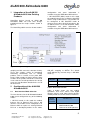
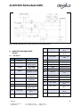
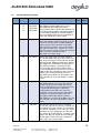
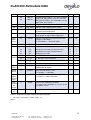
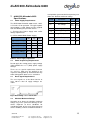
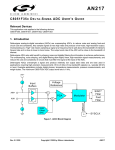
dLAN 200 AVmodule 6400
Data sheet
DESCRIPTION
The dLAN 200 AVmodule 6400 is an integrated device for transmitting and receiving data over
the power line. It holds all functions necessary for the easy creation of HomePlug AV network
devices.
The host interface can be configured to run in two alternative modes:
PHY Mode
As MII PHY interface (IEEE 802.3u 1995, paragraph 22) for interconnection with microcontrollers or Ethernet MAC controllers,
Power Supply
Host Controller
VCORE
VDD
VAA
MII
Tx
PLC
Rx
43 Pin SIP Connector
Host/DTE Mode
As MII host/DTE interface (IEEE 802.3u 1995, paragraph 22) for connecting to an Ethernet
PHY.
INT6400
Linedriver
/ Filters
PLC Rx&Tx
Fig. 1: Block Diagram of the devolo dLAN 200 AVmodule 6400
Revision 6 – 0112/42293
FEATURES
• up to 200 Mbps data rate on the power
line
• 750 m range via coaxial cable
• 400 m range via telephone line
• 300 m range via power cable
• Fully compatible with the HomePlug AV
standard
• Open API for status information and
device configuration
• Quality of service (QoS)
• 128 bit AES network encryption
• Fully integrated HomePlug AV power line
networking controller with integrated MII
(MAC or PHY mode) interfaces
• INT6400 Chipset
• Simplifies development cycle, assembly,
testing, and certification approvals
• Physical dimensions: 27,5mm x 69,5mm
• Cost-optimized design
• Designed for small-footprint embedded
applications
APPLICATIONS
• Backbone for WiFi and UWB
• Higher data rate broadband sharing
• Audio and video streaming as well as file
transfer, TV, STB, IPTV
• Voice over Internet Protocol (VoIP)
• Security Cameras
• Automated Meter Reading (AMR) / Smart
Metering
• Home Automation
• Flush-mounting
1
devolo AG
Charlottenburger Allee 60
D-52068 Aachen
Tel.: +49 (0)241-182 79 0
Fax: +49 (0)241-182 79 999
www.devolo.com
[email protected]
dLAN 200 AVmodule 6400
Devolo provides two different variants:
dLAN 200 AVmodule 6400:
connector male 90°.
dLAN 200 AVmodule 6400 horizontal: connector male 180°.
This document will mainly refer to the standard variant “dLAN 200 AVmodule 6400” for simplicity
reasons.
Contents
1
Integration of the dLAN 200 AVmodule 6400 into Existing Products ............. 3
2
Configuration of the dLAN 200 AVmodule 6400 ................................................... 3
2.1 Host Interface Mode Selection ............................................................................ 3
2.2 MII Ethernet PHY Configuration .......................................................................... 4
2.3 PIN Connections for MII (Ethernet) Modes ...................................................... 4
3
Security Pushbutton ..................................................................................................... 5
4
GPIO’s............................................................................................................................... 5
4.1 System Status LED Indicators ............................................................................ 5
5
Application Examples .................................................................................................. 7
5.1 dLAN 200 AVmodule 6400 based Wallplug HomePlug Device................... 7
5.2 Hybrid Device for power line, coaxial cable, telephone cable.................... 7
6
dLAN 200 AVmodule 6400 Pinout ............................................................................. 8
6.1 Pin Names ................................................................................................................. 8
6.2 Pin Descriptions by Group ................................................................................. 10
7
dLAN 200 AVmodule 6400 Specifications ............................................................ 13
7.1 Power Supply Requirements ............................................................................. 13
7.2 Power Sequencing Requirements.................................................................... 13
7.3 Reset Signal Requirements ............................................................................... 13
7.4 Absolute Maximum Ratings ............................................................................... 13
7.5 DC Characteristics ............................................................................................... 14
7.6 Mechanical Specifications ................................................................................. 14
8
Revision History .......................................................................................................... 14
2
devolo AG
Charlottenburger Allee 60
D-52068 Aachen
Tel.: +49 (0)241-182 79 0
Fax: +49 (0)241-182 79 999
www.devolo.com
[email protected]
dLAN 200 AVmodule 6400
1
Integration of the dLAN 200
AVmodule 6400 into Existing
Products
HomePlug devices based on dLAN 200
AVmodule 6400 can have their designs
partitioned into the major sections shown in
figure 2.
The HomePlug add-in consists of two sections:
configuration and status information is
available using the IEEE 802.3 MDI interface.
• MII HOST/DTE (MAC) mode: In this mode
the module behaves like an Ethernet host/DTE
device using an MII interface. The module can
be configured in MII Host/DTE mode to
connect to any other device that behaves like
an Ethernet PHY. In the MII host/DTE mode,
configuration and status information is
available using the IEEE 802.3 MDI interface.
Fig. 2: Enabled products general architecture
The dLAN 200 AVmodule 6400 and the
coupling and AC zero-cross detector circuitry.
These two sections suffice to incorporate
HomePlug functionality into an existing
product, such as a router, access point, MP3
player, video extender, or game console. Other
sections of the product should be reviewed to
ensure that the overall operation of the design
meets the considerations detailed in the rest of
this datasheet.
2
Configuration of the dLAN 200
AVmodule 6400
2.1
Host Interface Mode Selection
The host interface for the dLAN 200 AVmodule
6400 can be configured to any of the following
modes:
• MII PHY mode: In this mode the module
behaves like an Ethernet PHY using a MII
interface. The module can be configured as an
Ethernet PHY to replace an existing Ethernet
PHY on a developed product. In this mode,
Host mode is selected through the use of the
HM_SEL strapping at GPIO8. The default
mode without any external straps is MII MAC
mode (1).
HM_SEL
Mode
0
MII PHY
1
MII MAC
Table 1: Host mode selection
Table 2 below shows the two module
operations and cases where each digital
interface may be used. Most existing designs
should provide at least one of these interfaces.
Digital
Interface
Operation
Possible Use
PHY Mode
Router or Switch, the dLAN
200 AVmodule 6400
connects to an MII port on a
3
devolo AG
Charlottenburger Allee 60
D-52068 Aachen
Tel.: +49 (0)241-182 79 0
Fax: +49 (0)241-182 79 999
www.devolo.com
[email protected]
dLAN 200 AVmodule 6400
switch chip
Networked device using
network processor with MII
such as networking gaming
and modems
Bridging devices between
other networking
technologies and MII
PCI Card, the dLAN 200
AVmodule 6400 connects to
a PCI/MII bridge chip
MAC Mode
Ethernet to HomePlug
Adapters
Device with an integrated
PHY available, but no MII
available - use an
inexpensive MII PHY to
make a PHY-to-PHY
connection
Table 2: Typical uses for digital interface
operations
2.2
MII Ethernet PHY Configuration
There are additional configuration straps that
are unique to the MII Ethernet PHY mode of
operation shown in Tables 3 to Table 7. Speed
select sets the MII data rate. Auto-negotiation
select enables auto-negotiation or defaults the
MII to speed and duplex settings. After the
modules firmware has been booted the AutoNegotiation, speed and duplex settings will be
overwritten by configurable values. Isolate
controls whether MII signals are active or tristated.
MD_A[4:3]
MII Management
Address
00
0x00
01
0x08
10
0x10
11
0x18
Table 6: MII Ethernet PHY Mode Management
Address Selection
2.3
PIN Connections for MII (Ethernet)
Modes
Proper connections of the configuration straps
mentioned above are detailed in Table 8 for
both modes of operation.
PU Signal should be pulled up to VCCI/O
through a 10 kΩ resistor,
PD Signal should be pulled down to VSS
through a 10 kΩ resistor.
Signal
Name
MII(Ethernet)
MAC Mode
Connection
MII(Ethernet) PHY
Mode Connection
MD_A4
PU or PD
MD_A4 Option
Select
MD_A3
PU or PD
MD_A3 Option
Select
ANEN
PU or PD
ANEN Option Select
SPEED
PU or PD
SPEED Option
Select
SPEED
MII Speed
DUPLEX
NC
Not connected
0
10 Mbps
ISODEF
PD
1
100 Mbps
ISODEF Option
Select
Table 7: Connections of configuration straps
Table 3: MII Ethernet PHY Mode Speed Selection
ANEN
Auto-negotiation
0
Use link speed selection
strap
1
Enable auto-negotiation
Table 4: MII Ethernet PHY Mode Auto-negotiate
Selection
ISODEF
Isolation
0
Normal Operation
1
Isolated
Table 5: MII Ethernet PHY Mode Isolate Selection
4
devolo AG
Charlottenburger Allee 60
D-52068 Aachen
Tel.: +49 (0)241-182 79 0
Fax: +49 (0)241-182 79 999
www.devolo.com
[email protected]
dLAN 200 AVmodule 6400
3
(Figure 4)
Security Pushbutton
The security pushbutton provides an easy
method for pairing two or more dLAN devices.
By pressing the pushbutton for a short period
of time on each device that should be added to
the network the devices are connected as if
they had the same password.
+3.3V
10K
Table 8: boot strapping configuration
4.1
System Status LED Indicators
The system status LED indicators are
controlled by routines in the MAC firmware.
The status LED indicator configuration is listed
in Table 10. The both signals GPIO8 and
GPIO10 for the Powerline Link indication can
be connected to a dual colour LED to realize a
throughput indicator which indicates four states
shown in Table 9.
Dual LED
colour
Module
Pushbutton
green
orange
red
100pF
off
GND
A schematic of the pushbutton circuitry
appears in Figure 3. When the pushbutton is
pressed the pushbutton pin is pulled to ground
(logical ‘0’).
GPIO’s
The four GPIO’s (GPIO8, 9, 10 and
LED_PWR) are used for system status
indication. Although three of these GPIO’s
(GPIO8, 9 and 10) are used as boot strap
configuration. Their state will be latched during
the positive edge of the reset signal. You can
connect a LED according to Figure 4 or 5, or
must at least connect the 3.3 kΩ resistor. The
possible configurations are shown in Table 8.
Pin
MII(Ethernet)
MAC Mode
MII(Ethernet)
PHY Mode
GPIO8
HM_SEL
Pull up
(Figure 4)
Pull down
(Figure 5)
GPIO9
Pull down
(Figure 5)
Pull down
(Figure 5)
GPIO10
Pull up
Pull up
GPIO10 PLC status
ON
OFF
Good
connection
ON
ON
Medium
connection
OFF
ON
Poor
connection
OFF
OFF
No
connection
Figure 4 and Figure 5 illustrate how a pull-up
or pull-down resistor can be connected to
control each LED and provide the appropriate
configuration. The LED_PWR LED indicator
should be connected to ground. Component
values in these figures are typical. The value of
the series current limiting resistor is selected
based on the desired LED current. Note that
the maximum LED current should be limited to
12 mA.
5
devolo AG
Charlottenburger Allee 60
D-52068 Aachen
GPIO8
Table 9: throughput indication
GND
Fig. 3: Pushbutton circuitry
4
(Figure 4)
Tel.: +49 (0)241-182 79 0
Fax: +49 (0)241-182 79 999
www.devolo.com
[email protected]
dLAN 200 AVmodule 6400
Status LED
Module Pin
LED State
On
Flash
Off
Power
LED_PWR
Ready
Load Firmware
Not Ready
Host/Ethernet Link
GPIO9
Ethernet Link
detected
Transmit or
Receive Activity
No Link detected
Powerline Link Red
GPIO10
Powerline Link Green
GPIO8
refer to Table 9. Flashing indicates transmit or receive
activity on the powerline.
Table 10: Status LED indicator configuration
3.3V
dLAN
Module
I/O Pin
3.3K
680
3.3K
680
dLAN
Module
I/O Pin
Pull-up LED Strapping
Pull-down LED Strapping
Fig. 4 and 5: LED strapping
6
devolo AG
Charlottenburger Allee 60
D-52068 Aachen
Tel.: +49 (0)241-182 79 0
Fax: +49 (0)241-182 79 999
www.devolo.com
[email protected]
dLAN 200 AVmodule 6400
5
Application Examples
5.1
dLAN 200 AVmodule 6400 based
Wallplug HomePlug Device
The recommended add-in circuitry is shown
below.
Coupling capacitors and the secondary of the
coupling transformer form a high-pass filter
that allows the Powerline communications
signal to pass, but blocks 50/60Hz AC sine
wave. The resistors parallel to the capacitors
serve to discharge the coupling capacitors
when the device is removed from the AC line.
Fig. 6: dLAN 200 AV module based wall module HomePlug device
In Figure 6, MOV is the first transient
protection stage and limits large voltage
spikes. For
230Vac networks at least a
300Vac MOV should be used. The Schottky
diodes and resistors circuitry is a necessary
transient and overvoltage protection in TX+/path.
5.2
The AC zero cross detector is based on an
opto-isolator to provide the required safety
isolation between the power line and the low
voltage secondary circuitry. The LED of the
opto-isolator is connected to the power line in
series with two high value resistors. The
resistors limit the current (and voltage) that can
flow through the LED during both forward
conduction (ON state) and reverse bias (OFF
state). The emitter of the phototransistor
connects to low voltage ground, and the
collector is pulled up to +3.3VDC to provide the
isolated logic level detector output.
The hybrid bridge of Figure 7 safely couples
communication
signals
between
the
communication node Analog Transmit and
Receive connector pins and the power line or
the coaxial media. In this mode of operation
hybrid networking over power line and coax
media is provided. The device also works as a
bridge between the coax media and the power
line, so that the signals of other communication
nodes can be routed between the two
interfaces.
The high capacitances of the LED and
phototransistor result in a relatively slow
response time. The slow response provides
low pass filtering which greatly reduces timing
shift from noise or OFDM signals on the power
line.
The same technology for data communication
over power lines is also ideally suited for
communication over other wired media
including coaxial cable & telephone cable.
For the hybrid bridge the same Zero-Cross
detector circuitry is used as for the wall plug
device. The transformer couples the module,
the coax connector, and the power line. Also,
the same high pass filter is used to block the
50/60 Hz sine wave.
7
devolo AG
Charlottenburger Allee 60
D-52068 Aachen
Hybrid Device for power line, coaxial
cable, telephone cable
Tel.: +49 (0)241-182 79 0
Fax: +49 (0)241-182 79 999
www.devolo.com
[email protected]
dLAN 200 AVmodule 6400
Fig. 7: Hybrid communication circuitry: Power line and coaxial interface
6
dLAN 200 AVmodule 6400
Pinout
6.1
Pin Names
Pin No.
Pin Name
Function
1
DUPLEX
Not connected
2
SPEED
MII (Ethernet)
Speed Select
12
MII_RXD1
MII Receive Data
Bit 1
13
MII_RXD0
MII Receive Data
Bit 0
14
MII_RXDV
MII Receive Data
Valid
15
MII_RXCLK
MII Receive Clock
16
MII_CRS
MII Carrier Sense
17
MII_RXER
MII Receive Error
18
GND
Ground Reference
19
GPIO9
Ethernet Link LED
20
GPIO10
Powerline Link LED
red
21
MII_TXCLK
MII Transmit Clock
3
ISODEF
Isolate Mode
Default Value
4
ANEN
MII (Ethernet) Auto
Negotiation Enable
5
VCORE
+1.05V with respect
to ground
6
VCORE
+1.05V with respect
to ground
22
MII_TXEN
MII Transmit Enable
23
MII_COL
MII Collision Detect
24
MII_TXD0
MII Transmit Data
Bit 0
7
GND
Ground reference
8
Pushbutton
Security Pushbutton
9
LINE_SYNC
AC line zero-cross
detect signal
25
MII_TXD1
MII Transmit Data
Bit 1
10
MII_RXD3
MII Receive Data
Bit 3
26
MII_TXD2
MII Transmit Data
Bit 2
11
MII_RXD2
MII Receive Data
Bit 2
27
MII_TXD3
MII Transmit Data
Bit 3
8
devolo AG
Charlottenburger Allee 60
D-52068 Aachen
Tel.: +49 (0)241-182 79 0
Fax: +49 (0)241-182 79 999
www.devolo.com
[email protected]
dLAN 200 AVmodule 6400
28
GND
Ground Reference
37
GPIO8
29
MD_A3
MII Management
Address Bit 3
Powerline Link LED
green / HM_SEL
38
GND
Ground Reference
30
MD_A4
MII Management
Address Bit 4
39
TX
Analog Transmit
Output to Coupler
31
MII_MDIO
MII mgmt data I/O
40
TXn
32
MII_MDCLK
MII mgmt data clock
Analog Transmit
Output to Coupler
33
VDD
+3.3V with respect
to ground
41
RXn
Analog Receive
Input from Coupler
34
VDD
+3.3V with respect
to ground
42
RX
Analog Receive
Input from Coupler
35
RESET
Resets all module
logic then low
43
VAA
+11V with respect
to ground
36
LED_PWR
LED Driver Output –
Indicates Power
Good (default
setting)
Table 11: dLAN 200 AVmodule 6400 pin I/O
9
devolo AG
Charlottenburger Allee 60
D-52068 Aachen
Tel.: +49 (0)241-182 79 0
Fax: +49 (0)241-182 79 999
www.devolo.com
[email protected]
dLAN 200 AVmodule 6400
6.2
Pin Descriptions by Group
Group
Pin No
Signal Name
Description
MAC
Mode
PHY
Mode
MII
13
12
11
10
MII_RXD0
MII_RXD1
MII_RXD2
MII_RXD3
MII Receive Data. The PHY controller drives
MII_RXD[3:0] and the MAC core receives
MII_RXD[3:0]. MII_RXD[3:0] transition
synchronously with respect to MII_RXCLK. For
each MII_RXCLK period in which MII_RXDV is
asserted, MII_RXD[3:0] is valid. MII_RXD0 is
the least-significant bit. The PHY controller tristates MII_RXD[3:0] in isolate mode.
I
O
15
MII_RXCLK
MII Receive Clock. MII_RXCLK is a continuous
clock that provides the timing reference for the
transfer of the MII_RXDV and MII_RXD[3:0]
signals from the PHY controller to the MAC
core. The PHY controller sources MII_RXCLK.
MII_RXCLK frequency is equal to 25% of the
data rate of the received signal on the Ethernet
cable. The PHY controller tri-states
MII_RXCLK in isolate mode.
I
O
14
MII_RXDV
MII Receive Data Valid. The PHY controller
asserts MII_RXDV to indicate to the MAC core
that it is presenting the recovered and decoded
data bits on MII_RXD[3:0] and that the data on
MII_RXD[3:0] is synchronous to MII_RXCLK.
MÍI_RXDV transitions synchronously with
respect to MII_RXCLK. MII_RXDV remains
asserted continuously from the first recovered
nibble of the frame through the final recovered
nibble, and is deactivated prior to the first
MII_RXCLK that follows the final nibble. The
PHY controller tri-states MII_RXDV in isolate
mode.
I
O
17
MII_RXER
MII Receive Error. The PHY controller asserts
MII_RXER high for one or more MII_RXCLK
periods to indicate to the MAC core that an
error (a coding error or any error that the PHY
is capable of detecting that is otherwise
undetectable by the MAC) was detected
somewhere in the current frame. MII_RXER
transitions synchronously with respect to
MII_RXCLK. While MII_RXDV is inactive,
MII_RXER has no effect on the MAC core. The
PHY controller tri-states MII_RXER in isolate
mode.
I
O
23
MII_COL
MII Collision Detected. The PHY controller
asserts MII_COL when it detects a collision on
the medium. MII_COL remains asserted while
the collision condition persists. MII_COL signal
transitions are not synchronous to either the
MII_TXCLK or the MII_RXCLK. The MAC core
ignores the MII_COL signal when operating in
the full-duplex mode. The PHY controller tristates MII_COL in isolate mode.
I
O
10
devolo AG
Charlottenburger Allee 60
D-52068 Aachen
Tel.: +49 (0)241-182 79 0
Fax: +49 (0)241-182 79 999
www.devolo.com
[email protected]
dLAN 200 AVmodule 6400
24
25
26
27
MII_TXD0
MII_TXD1
MII_TXD2
MII_TXD3
MII Transmit Data. The MAC core drives
MII_TXD[3:0] and the PHY controller receives
MII_TXD[3:0]. MII_TXD[3:0] transitions
synchronously with respect to MII_TXCLK. For
each MII_TXCLK period in which MII_TXEN is
asserted, MII_TXD[3:0] is valid. MII_TXD0 is
the least-significant bit. The PHY controller
ignores MII_TXD[3:0] in isolate mode.
O
I
21
MII_TXCLK
MII Transmit Clock. MII_TXCLK is a
continuous clock that provides a timing
reference for the transfer of the MII_TXEN and
MII_TXD[3:0] signals from the MAC core to the
PHY controller. The PHY controller sources
MII_TXCLK. The operating frequency of
MII_TXCLK is 25 MHz when operating at 100
Mbps and 2.5 MHz when operating at 10
Mbps. The PHY controller tri-states
MII_TXCLK in isolate mode.
I
O
22
MII_TXEN
MII Transmit Enable. A high assertion on
MII_TXEN indicates that the MAC core is
presenting nibbles to the PHY controller for
transmission. The INT6000 MAC core asserts
MII_TXEN with the first nibble of the preamble
and keeps MII_TXEN asserted while all nibbles
to be transmitted are presented to the MII.
MII_TXEN is deactivated prior to the first
MII_TXCLK following the final nibble of the
frame. MII_TXEN transitions synchronously
with respect to MII_TXCLK. The PHY controller
ignores MII_TXEN in isolate mode.
O
I
16
MII_CRS
MII Carrier Sense. The PHY controller asserts
MII_CRS when either transmit or receive
medium is non-idle. The PHY deasserts
MII_CRS when both transmit and receive
medium are idle. The PHY must ensure that
MII_CRS remains asserted throughout the
duration of a collision condition. The transitions
on the CRS signal are not synchronous to
either the MII_TXCLK or the MII_RXCLK. The
PHY controller tri-states MII_CRS in isolate
mode.
I
O
31
MII_MDIO
MII Management Data In/Out. This is the data
input signal from the PHY controller. The PHY
drives the Read Data synchronously with
respect to the MII_MDCLK clock during the
read cycles. This is also the data output signal
from the MAC core that drives the control
information during the Read/Write cycles to the
PHY controller. The MAC core drives the
MII_MDCLK signal
I/O
I/O
32
MII_MDCLK
MII Management Data Clock. The MAC core
sources MDC as the timing reference for
transfer of information on the MII_MDIO
signals. MII_MDCLK signal has no maximum
high or low times. MII_MDCLK minimum high
and low times are 160 ns each, and the
O
I
11
devolo AG
Charlottenburger Allee 60
D-52068 Aachen
Tel.: +49 (0)241-182 79 0
Fax: +49 (0)241-182 79 999
www.devolo.com
[email protected]
dLAN 200 AVmodule 6400
minimum period for MII_MDCLK is 400 ns.
29
30
MD_A3
MD_A4
MII Management Address. The PHY Controller
samples M_A[4:3] during reset to set the MII
Management address; the valid addresses are
0x00, 0x08, 0x10 & 0x18.
-*
I
Control
9
LINE_SYNC
AC line zero-cross detect signal
I
I
LEDs
36
LED_PWR
Indicates Power Good (default setting)
O
O
19
GPIO9
Indicates Ethernet link and activity, strap to low
for proper boot configuration
I/O
I/O
20
GPIO10
Indicates Powerline Link Status (red LED),
strap to high for proper boot configuration
I/O
I/O
Host
Mode
Select
37
GPIO8
Indicates Powerline Link Status(green LED),
configures Host Mode:
0 = PHY Mode; 1 = Host/DTE Mode
I/O
I/O
Reset
35
RESET
Resets all module logic when low
I
I
AFE
39
40
41
42
TX
TXn
RXn
RX
Analog Transmit Output
Analog Transmit Output (complementary)
Analog Receive Input (complementary)
Analog Receive Input
O
O
I
I
O
O
I
I
Ground Reference
I
I
VCORE
+1.05V with respect to ground
I
I
33,34
VDD
+3.3V with respect to ground
I
I
43
VAA
+11V with respect to ground
I
I
Duplex
Select
1
DUPLEX
Not connected, Function is not supported by
INT6400 based module
-*
I
Speed
Select
2
SPEED
Determine MII interface rate:
0 = 10 Mbps; 1 = 100 Mbps
-*
I
Isolate
Mode
Default
Value
3
ISODEF
Determine default mode for MII Bus:
1 = isolate; 0 = normal operation
-*
I
Auto
Negotiati
on
Enable
4
ANEN
Control auto negotiation capability:
1 = enable auto negotiation; 0 = use the speed
and duplex selects
-*
I
Pushbutt
on
8
Pushbutton
Connector for pushbutton signal
I
I
Power & 7,18,28,38
Ground
5,6
Ground
Table 12: dLAN 200 AVmodule 6400 pin description by group
* - for proper connection in MAC mode see
table 7
12
devolo AG
Charlottenburger Allee 60
D-52068 Aachen
Tel.: +49 (0)241-182 79 0
Fax: +49 (0)241-182 79 999
www.devolo.com
[email protected]
dLAN 200 AVmodule 6400
7
not implied or guaranteed when operating at or
above the Absolute maximum ratings.
dLAN 200 AVmodule 6400
Specifications
7.1
Power Supply Requirements
The dLAN 200 AVmodule 6400 needs 1.05V,
3.3V and 11V for operation. The typical power
consumption is 2.5W. Power may be supplied
from the following two possible sources:
1.) Existing Host Power Supply with similar
voltage requirements
2.) Off line Switch Mode Power Supply
Min
Typ
Max
VCC Supply Voltage
1.00 V 1.05 V 1.10 V
VCC Supply Current
600mA 800mA
VDD Supply Voltage
3.13 V 3.30 V 3.47 V
VDD Supply Current
200mA 300mA
VAA Supply Voltage
10.5 V 11.0 V 11.5 V
VAA Supply Current
80 mA 80 mA
Symbol
Parameter
VCC
Core Supply Voltage
-0.3 V 1.2 V
VIO
I/O Voltage
VSS VDD
-0.3 V +0.3 V
VDD
VAA
TSTORE
Min
Power Supply Voltage -0.3 V 3.6 V
Analog Voltage
-0.3 V 12.5 V
Storage Temperature -40 °C 125
°C
TOPERATE Operation Temperature 0°C
VESD
Max
Electrostatic Discharge
60°C
1000
V
Table 14: Absolute maximum ratings
130
mA
Table 13: Power supply requirements
7.2
Power Sequencing Requirements
Do not apply the analog power supply voltage
(VAA) without the 3.3 V (VDD) power supply
voltage!
There are no special requirements between
VCC and VDD. Both may be applied in any
sequence during power up and removed in any
order during power down versus each other.
7.3
Reset Signal Requirements
The reset signal has to be driven low for at
least 100 ms after all supply voltages are
stable.
Fig. 8: Reset timing – tRSTa = 100 ms min.
7.4
Absolute Maximum Ratings
Operation at or above the absolute maximum
ratings may cause permanent damage to the
device. Exposure to these conditions for
extended periods of time may affect long-term
device reliability. Correct functional behavior is
13
devolo AG
Charlottenburger Allee 60
D-52068 Aachen
Tel.: +49 (0)241-182 79 0
Fax: +49 (0)241-182 79 999
www.devolo.com
[email protected]
dLAN 200 AVmodule 6400
7.5
DC Characteristics
Parameter
Test Conditions
Min
Low-level
input voltage
Max
0.8 V
High-level
input voltage
2.0V
1
Low-level
IOL=4mA, 12mA
output voltage
8
Revision History
Revision
Modifications
1
• Original Issue
2
• Sample circuits updated with
fuse
0.4 V
High-level
output voltage
IOH=-4mA, 2
12mA
2.4V
Low-level
input current
VI=GND
-1µA
High-level
input current
VI=VDD
HighGND ≤ VI ≤ VDD -1µA
impedance
output current
• Current consumption
updated
1µA
3
• Pinout of ISODEF and
DUPLEX corrected
4
• minor
5
• Fig.: 9 updated
• GPIO / LED behaviour
changed
1µA
Table 15: DC characteristics
• Power Sequencing
Requirements
6
• Added: description of second
variant (horizontal mounting)
1) IOL= 12mA for status LEDs
• Added description of
transient and overvoltage
protection in TX+/- path.
IOL= 4mA for all other interfaces
2) IOH= -12mA for status LEDs
• Recommended Varistor
changed to 300Vac type
IOH= -4mA for all other interfaces
7.6
Mechanical Specifications
The dLAN 200 AVmodule 6400 is connected
via an industry standard header using 0.40mm
square pins on 0.127mm centers. For easy
insertion and removal of module devices a
mating female connector can be used.
Alternatively, the device may be soldered
directly to the host board.
© 2009 devolo AG, Aachen (Germany)
The card dimensions including connector are:
devolo, dLAN and the devolo logo are registered
trademarks of devolo AG.
•
•
69.5 x 32.64 x 8.8 mm
(dLAN 200 AVmodule 6400)
While the information in this data sheet has been
compiled with great care, it may not be deemed an
assurance of product characteristics. devolo shall
be liable only to the degree specified in the terms of
sale and delivery.
®
Subject to change without notice. No liability for
technical errors or omissions.
69.5 x 27.5 x 13.8 mm
(dLAN 200 AVmodule 6400 horizontal)
14
devolo AG
Charlottenburger Allee 60
D-52068 Aachen
Tel.: +49 (0)241-182 79 0
Fax: +49 (0)241-182 79 999
www.devolo.com
[email protected]
dLAN 200 AVmodule 6400
Fig. 9: dLAN 200 AVmodule 6400 dimensions
Fig. 10: dLAN 200 AVmodule 6400 horizontal dimensions
15
devolo AG
Charlottenburger Allee 60
D-52068 Aachen
Tel.: +49 (0)241-182 79 0
Fax: +49 (0)241-182 79 999
www.devolo.com
[email protected]