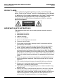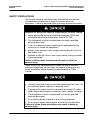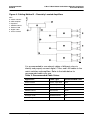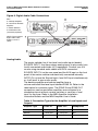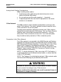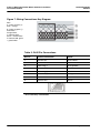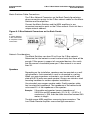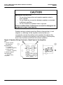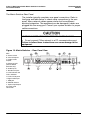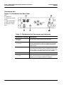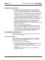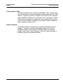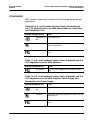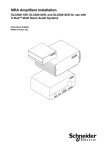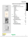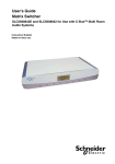
1
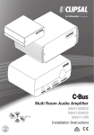
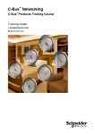
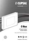
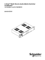
C-Bus™ Multi Room Audio Matrix Switcher Installation SLC5608842 and SLC5608842E Instruction Bulletin Retain for future use. C-Bus™ Multi Room Audio Matrix Switcher Installation Instruction Bulletin 63249-420-265A2 04/2010 HAZARD CATEGORIES AND SPECIAL SYMBOLS Read these instructions carefully and look at the equipment to become familiar with the device before trying to install, operate, service, or maintain it. The following special messages may appear throughout this bulletin or on the equipment to warn of potential hazards or to call attention to information that clarifies or simplifies a procedure. The addition of either symbol to a “Danger” or “Warning” safety label indicates that an electrical hazard exists which will result in personal injury if the instructions are not followed. This is the safety alert symbol. It is used to alert you to potential personal injury hazards. Obey all safety messages that follow this symbol to avoid possible injury or death. Danger indicates an immediately hazardous situation which, if not avoided, will result in death or serious injury. Warning indicates a potentially hazardous situation which, if not avoided, can result in death or serious injury. Caution indicates a potentially hazardous situation which, if not avoided, can result in minor or moderate injury. Caution, used without the safety alert symbol, indicates a potentially hazardous situation which, if not avoided, can result in property damage or improper operation. NOTE: Provides additional information to clarify or simplify a procedure. 2 © 2010 Schneider Electric. All Rights Reserved. 63249-420-265A2 04/2010 C-Bus™ Multi Room Audio Matrix Switcher Installation Instruction Bulletin PLEASE NOTE Electrical equipment should be installed, operated, serviced, and maintained only by qualified personnel. This document is not intended as an instruction manual for untrained persons. No responsibility is assumed by Schneider Electric for any consequences arising out of the use of this manual. FCC CLASS B This device complies with Part 15 of the FCC Rules. Operation is subject to the following two conditions: (1) this device may not cause harmful interference, and (2) this device must accept any interference received, including interference that may cause undesired operation. This equipment has been tested and found to comply with the limits for a Class B digital device, pursuant to Part 15 of the FCC Rules. These limits are designed to provide reasonable protection against harmful interference in a residential installation. This equipment generates, uses, and can radiate radio frequency energy and, if not installed and used in accordance with the instructions, may cause harmful interference to radio communications. However, there is no guarantee that interference will not occur in a particular installation. If this equipment does cause harmful interference to radio or television reception, which can be determined by turning the equipment off and on, the user is encouraged to try to correct the interference by one or more of the following measures: Reorient or relocate the receiving antenna. Increase the separation between the equipment and receiver. Connect the equipment into an outlet on a circuit different from that to which the receiver is connected. Consult the dealer or an experienced radio/TV technician for help. Changes or modifications to this device that are not expressly approved by Schneider Electric could void the user's authority to operate this equipment. © 2010 Schneider Electric. All Rights Reserved. 3 C-Bus™ Multi Room Audio Matrix Switcher Installation Instruction Bulletin 63249-420-265A2 04/2010 PRODUCT LABEL Refer to the warning label appearing on the product illustrated below. Refer to the "Notices" section at the beginning of this bulletin for definitions of the symbols appearing on the label. Carefully read and follow the safety precautions both on the equipment and contained in this bulletin before attempting to install or maintain electrical equipment. IMPORTANT SAFETY INSTRUCTIONS The appliance coupler shall remain readily operable once the product is installed. 1. Read these instructions. 2. Keep these instructions. 3. Heed all warnings. 4. Follow all instructions. 5. Do not use this apparatus near water. 6. Clean only with dry cloth. 7. Do not block any ventilation openings. Install in accordance with the manufacturer’s instructions. 8. Do not install near any heat sources such as radiators, heat registers, stoves, or other apparatus (including amplifiers) that product heat. 9. Do not defeat the purpose of the polarized or grounding-type plug. A polarized plug has two blades with one wider that the other. A grounding type plug has two blades and a third grounding prong. The wide blade or the third prong are provided for your safety. If the provided plug does not fit into your outlet, consult an electrician for replacement of the obsolete outlet. 10. Protect the power cord from being walked on or pinched particularly at plugs, convenience receptacles, and the point where the exit from the apparatus. 11. Only use the attachments/accessories specified by the manufacturer. 12. When a cart is used, use caution when moving the cart/apparatus combination to avoid injury from tip-over. 13. Unplug this apparatus during lightning storms or when unused for long periods of time. 14. Refer all servicing to qualified service personnel. Servicing is required when the apparatus has been damaged in any way such as power supply cord or plug is damaged, liquid has been spilled or objects have fallen into the apparatus, the apparatus has been exposed to rain or moisture, does not operate normally, or has been dropped. 4 © 2010 Schneider Electric. All Rights Reserved. 63249-420-265A2 04/2010 C-Bus™ Multi Room Audio Matrix Switcher Installation Instruction Bulletin INTRODUCTION This bulletin provides instructions for installing a C-Bus™ Multi-Room Audio (MRA) system. The system uses a C-Bus network to distribute and control sound. The MRA system can also be controlled with other C-Bus input units (e.g., Keypads or Touch Screens). The system also has remote-control capabilities. Designed for maximum flexibility and customization, an MRA system can be installed in matrix or standalone configurations to form up to eight audio zones. Amplifiers can be located centrally or they can be located remotely with the speakers. Up to 8 amplifiers can be connected to a matrix switcher and up to 3 matrix switchers can be connected on a C-Bus network. When installing MRA amplifiers in a standalone layout (without a matrix switcher), refer to the MRA Amplifier Installation Instructions, and the MRA Amplifier User's Guide as well as other specific MRA information found on the web at www.schneider-electric.us. Read the Important Safety Instructions section before you begin. After completing the hardware installation tasks, you must program the MRA Matrix Switcher and MRA amplifiers using the configuration software. Before You Begin Before you begin to set up a unit, verify that your order is complete by comparing the contents of the package with the appropriate items in the table below. Also verify that the catalog number on the box label matches your order. Figure 1: MRA System Components KEY: A. Matrix switcher B. Distribution unit C. Low power remote amplifier D. Remote amplifier E. Desktop amplifier © 2010 Schneider Electric. All Rights Reserved. 5 C-Bus™ Multi Room Audio Matrix Switcher Installation Instruction Bulletin 63249-420-265A2 04/2010 Figure 2: MRA Power Supplies KEY: A. High temperature power supply for MRA amplifiers B. Power supply adaptor for use with the Low Power Remote Amplifier C. Low power remote amplifier power supply Table 1: Multi Room Audio Product Catalog Numbers Catalog Number Product Description SLC5608842 MRA Matrix Switcher Standard model for C-Bus MRA systems. The Matrix Switcher distributes digital audio to up to 8 MRA zones. The switcher includes: • 4 stereo analogue inputs • 1 C-Bus digital audio1 optical input • 2 internal AM/FM tuners • 2 infrared (IR) emitter outputs SLC5608842E MRA Matrix Switcher, Deluxe Includes all of the features of the 560884/2, plus streaming audio capabilities using a LAN (with C-Bus Ripple software) or a USB source. Matrix Switchers • 2 rack ears for mounting Amplifiers SLC560125D MRA Desktop Amplifier SLC560125R MRA Remote Amplifier SLC560110R MRA Low Power Remote Amplifier SLC560100E Enclosure only Used with the low power remote amplifier SLC560011 MRA Distribution Unit Encodes a single stereo analogue source into C-Bus digital format. This allows for the connection of an additional audio source to the matrix switcher. Power Supplies SLC5600P243750T High temperature switch mode power supply SLC5600P241250 Power supply For the low power remote amplifier SLC5600P24500S Power supply For the distribution unit 6 © 2010 Schneider Electric. All Rights Reserved. 63249-420-265A2 04/2010 C-Bus™ Multi Room Audio Matrix Switcher Installation Instruction Bulletin SAFETY PRECAUTIONS This section contains important safety precautions that must be followed before attempting to install or maintain electrical equipment. Carefully read and follow the safety precautions below. HAZARD OF ELECTRIC SHOCK, EXPLOSION, OR ARC FLASH Apply appropriate personal protective equipment (PPE) and follow safe electrical work practices. See NFPA 70E. This equipment must be installed and serviced by qualified electrical personnel. Turn off all electrical power supplying this equipment before working on or inside the equipment. Always use a properly rated voltage sensing device to confirm that power is off. Replace all devices, doors, and covers before turning on power to this equipment. Failure to follow these instructions will result in death or serious injury. There are no user serviceable parts inside the Matrix Switcher enclosure. Replacing the fuse does not require opening the unit cover. Installation should typically be performed by a C-Bus installer. HAZARD OF ELECTRIC SHOCK, BURN, OR ARC FLASH Use only the power supply and cords supplied with the units. Do not substitute power supplies or electrical cords. Plug the unit's power cord into a properly-grounded AC power outlet. Never remove the grounding pin from a power cord plug. This equipment must be installed and serviced by qualified electrical personnel. Do not allow liquids to splash or drip on the equipment. Do not place cables where people are likely to trip over them. Failure to follow these instructions can result in death or serious injury. © 2010 Schneider Electric. All Rights Reserved. 7 C-Bus™ Multi Room Audio Matrix Switcher Installation Instruction Bulletin 63249-420-265A2 04/2010 NOTE: In the event of a spill, unplug the equipment immediately and contact technical support. The amplifiers can produce sounds loud enough to cause permanent hearing loss. HAZARD OF PERMANENT HEARING LOSS Keep volume controls at low levels when selecting program sources or when connecting local audio sources to an MRA amplifier. Plug the headphones into the MRA amplifier before placing the ear pieces on your head or in ears. Do not allow children to use the MRA equipment without adequate supervision. Failure to follow these instructions will result in serious injury. The MRA units require adequate ventilation. HAZARD OF OVERHEATING Do not cover or block the vents on the matrix switcher, MRA amplifiers or power supplies. Provide a clear space around the equipment, at least 2 inches (50 mm) to the front and rear and 0.6 inches (15 mm) above. Failure to follow these instructions can result fire, overheating equipment, or serious injury. 8 © 2010 Schneider Electric. All Rights Reserved. 63249-420-265A2 04/2010 C-Bus™ Multi Room Audio Matrix Switcher Installation Instruction Bulletin FEATURES The main features of the MRA system include: Each matrix switcher can distribute digital audio to up to 8 MRA amplifiers. You can install up to 3 matrix switchers on a C-Bus network. The matrix switcher can provide power for the attached amplifiers via the Digital Audio cables. You can connect an external power supply to an amplifier to increase its audio power output. The choice of the audio program for an amplifier can be made at the matrix switcher or in the audio zone where the program is playing. You can use C-Bus input devices to choose the source and to adjust volume, tone and muting. The AM/FM tuners inside the matrix switcher can distribute preset station choices to any of the audio zones. The deluxe matrix switcher distributes streaming audio from several sources using the C-Bus Ripple software application that runs on a PC. You can connect up to 4 stereo analogue line-level inputs to the matrix switcher. If you need to add another source input, you can install an MRA Distribution Unit and power supply. CABLING REQUIREMENTS There are two basic methods of cabling and installing the C-Bus MRA system. The two methods may be combined. Table 2: Cabling Methods METHOD 1: METHOD 2: With all amplifiers installed in a central location where the installation's A/V equipment is located. With the amplifiers distributed remotely throughout the installation. In the Cabling Method 1 - Centrally Located Amplifiers figure shows a typical installation where all of the amplifiers are located near the matrix switcher. The speaker wires run from the central location to the audio zones. The Cabling Method 2 - Remotely Located Amplifiers figure below shows the amplifiers placed remotely in the various zones. © 2010 Schneider Electric. All Rights Reserved. 9 C-Bus™ Multi Room Audio Matrix Switcher Installation Instruction Bulletin 63249-420-265A2 04/2010 Figure 3: Cabling Method 1 – Centrally Located Amplifiers KEY: A. Matrix switcher B. MRA amplifier C. Speakers 1. AM/FM antenna 2. Ethernet LAN 3. Digital audio 4. C-Bus network 10 © 2010 Schneider Electric. All Rights Reserved. 63249-420-265A2 04/2010 C-Bus™ Multi Room Audio Matrix Switcher Installation Instruction Bulletin Figure 4: Cabling Method 2 – Remotely Located Amplifiers KEY: A. Matrix switcher B. MRA amplifier C. Speakers 1. AM/FM antenna 2. Ethernet LAN 3. Digital audio 4. C-Bus network It is recommended to use network cables of different colors to identify and properly connect digital, C Bus, and LAN cables to the matrix switcher and amplifiers. Refer to the table below for recommended cable color use. Table 3: Recommended Cable Colors Application Cable Type Recommended Color C-Bus network Cat.5e, 4 pair UTP Pink Digital audio Cat.5e, 4 pair UTP Green Ethernet LAN Cat.5e, 4 pair UTP Blue AM/FM antenna RG6 coaxial Black Speakers 2-core insulated any Analogue audio Shielded coaxial any Infrared target 3-core insulated any © 2010 Schneider Electric. All Rights Reserved. 11 C-Bus™ Multi Room Audio Matrix Switcher Installation Instruction Bulletin 63249-420-265A2 04/2010 AM/FM Antenna Cabling The RG6 coaxial antenna cable is terminated at the matrix switcher rear panel with a Type-F connector. When using the cable for AM radio reception, you must break the shield in the cable at some point away from the matrix switcher and associated equipment. Figure 5 shows the cable modification required for AM reception. It is not required if you are using only FM reception. Figure 5: Cable Modification for AM Reception KEY: A. Shield (cut back) B. Outer insulation layer (cut back) C. Center conductor and insulation (do not cut) 1. To AM/FM antenna or splitter 2. To matrix switcher Refer to the MRA Application Guides and the MARPA Help for more information about selecting radio station presets. Digital Audio Cabling The Matrix Switcher sends the digital audio to each MRA amplifier. The Cat.5e Digital Audio cables are terminated at the Matrix Switcher using an RJ45 plug. The cable carries: 12 Digital audio signal 27 V d.c. to power the amplifier (see Note) Signals for Infrared (IR) distribution NOTE: The Matrix Switcher can provide power for multiple MRA amplifiers using the Digital Audio cable to distribute power. If you need more audio output power for an amplifier, an external power supply can be installed. © 2010 Schneider Electric. All Rights Reserved. 63249-420-265A2 04/2010 C-Bus™ Multi Room Audio Matrix Switcher Installation Instruction Bulletin Digital Audio Cabling Considerations Consider the following when connecting the Digital Audio cables: The Digital Audio outputs from the matrix switcher or distribution unit must only be used with MRA amplifiers. Use a specific color for Digital Audio cables. Green colored cable is recommended for use with Digital Audio. Do not exceed 147.5 ft. (45 m maximum cable length for individual Digital Audio cables. Avoid laying Digital Audio cables along side electrical power source cabling as electromagnetic interference (EMI) can disrupt the audio signal. The Digital Audio cable can be terminated at a wall plate and run the cables inside the wall to the amplifier, or a wall plate near the amplifier. Then you can use patch leads from the matrix switcher to the wall plate. NOTE: The MRA amplifiers can be configured using a loop in-loop out connection for digital audio and infrared. Do not use loop-in, loop-out connections for power. Additional amplifiers will require a separate power supply. Refer to the C-Bus Multi Room Audio Amplifier Installation Instructions. If loop-in, loop-out is required with the Low Power Remote amplifier, a RJ-45 splitter or RJ-45 combiner (2 female to 1 male, 8-pin passive) will be needed. The figure below shows the connections from the Matrix Switcher to the MRA amplifiers and an optional MRA distribution unit. The additional distribution unit provides an additional audio input source. © 2010 Schneider Electric. All Rights Reserved. 13 C-Bus™ Multi Room Audio Matrix Switcher Installation Instruction Bulletin 63249-420-265A2 04/2010 Figure 6: Digital Audio Cable Connections KEY: A. Desktop Amplifier B. Low Power Remote Amplifier C. Matrix Switcher D. Distribution Unit (secondary-optional) NOTE: The maximum digital audio cable length is 147.5 ft. (45m) Analog Audio The matrix switcher has 4 line-level local audio inputs labeled SOURCE INPUT. Use these stereo analog inputs to play audio from locally connected audio/video (A/V) equipment. Connect your A/V source using standard audio cables with RCA connectors. SOURCE INPUT 4 on the rear panel and the AUX input on the front panel of the matrix switcher are electrically connected internally. NOTE: Do not use the Source Input 4 and AUX input simultaneously as it will result in poor audio quality. The desktop amplifier and remote amplifier have a volume-controlled line-level input labelled ZONE IN. Refer to the table below for connector types. The ZONE IN and ZONE OUT connections can be used when amplifiers are configured in a standalone layout without a matrix switcher or serve as a 'local input' for the zone. Refer to the MRA Amplifier Installation Instruction Bulletin and the MRA Amplifier User's Guide. Table 4: Connection Types for the Amplifier's Local Inputs and Outputs Amplifier Type 14 LOCAL IN ZONE OUT Headphones Desktop 2 – RCA jacks 2 – RCA jacks 3.5 mm stereo Remote 2 – RCA jacks 2 – RCA jacks N/A Low Power Remote 3.5 mm stereo N/A N/A © 2010 Schneider Electric. All Rights Reserved. 63249-420-265A2 04/2010 C-Bus™ Multi Room Audio Matrix Switcher Installation Instruction Bulletin Analog Audio Cabling Considerations When installing audio cables: Avoid laying audio cable along side electrical power source cable to minimize EMI pickup. Do not earth ground the audio negative ( – ) terminals. A separate ground wire from the A/V equipment to the matrix switcher is not needed. C-Bus Network The MRA system's matrix switcher and amplifiers must be on the same C Bus network. The matrix switcher and each amplifier has a C-Bus connection on the rear panel. The high power amplifiers and matrix switcher use C-Bus network cables that are terminated with RJ45 plugs. The Low Power Remote Amplifier uses a removable screw terminal connector. You may daisy chain C-Bus connections at the units. If you use wall plates, they should be clearly marked as C-Bus connection points. Connection to the C-Bus Network The C-Bus network is connected to the MRA Remote and Desktop Amplifiers through two polarity sensitive RJ45 inputs located on the MRA Remote and Desktop Amplifiers. Connect the unit to the C-Bus network with Category 5 unshielded twisted pair C-Bus network cable, and a wired RJ45 plug. Refer to the "Wiring Connections Key Diagram" figure, and the "RJ45 Pin Connections" table for wiring and pin connection information. NOTE: To clearly distinguish C-Bus from other UTP Cat5 cables, it is recommended to use a different colored cable, or clearly label the C-Bus UTP Cat5 cable. NOTE: The Category 5 unshielded twisted pair C-Bus network cable and the wired RJ45 plug are provided by the installer. HAZARD OF ELECTRIC SHOCK, EXPLOSION, OR ARC FLASH Do not connect line voltage to any C-Bus terminal. Failure to follow this instruction can result in personal injury or equipment or property damage. © 2010 Schneider Electric. All Rights Reserved. 15 C-Bus™ Multi Room Audio Matrix Switcher Installation Instruction Bulletin 63249-420-265A2 04/2010 Figure 7: Wiring Connections Key Diagram KEY: A. C-Bus positive (+): blue + orange B. C-Bus negative (-): blue/white + orange/white C. Remote OFF: brown + brown/white* D. Remote ON: green + green/white* Table 5: RJ45 Pin Connections RJ Pin C-Bus Connection Color 1 Remote ON* Green/White 2 Remote ON* Green 3 C-Bus Neg (-) Orange/White 4 C-Bus Pos (+) Blue 5 C-Bus Neg (-) Blue/White 6 C-Bus Pos (+) Orange 7 Remote OFF* Brown/White 8 Remote OFF* Brown *Not internally connected. 16 © 2010 Schneider Electric. All Rights Reserved. 63249-420-265A2 04/2010 C-Bus™ Multi Room Audio Matrix Switcher Installation Instruction Bulletin Matrix Switcher Cable Connections The C-Bus Network Connectors on the Back Panels figure below shows connection points for the C-Bus network cables on the Matrix Switcher and the amplifiers. Connect the Matrix Switcher and the MRA amplifiers to any convenient connection point on the C-Bus network. Each unit has a unique network address. Figure 8: C-Bus Network Connectors on the Back Panels KEY: A. Matrix Switcher C-Bus connections B. Amplifiers C-Bus connections Network Considerations The Matrix Switcher can draw 22 mA from the C-Bus network. Determine the total network current load and verify that there will be enough C-Bus power to support all connected devices. Also verify that the amount of available power per C-Bus network is no more than 2A. Speakers Depending on the installation, speakers may be mounted on a wall using brackets, flush mounted in a wall or concealed in a ceiling. When you mount speakers on brackets, you should install a wall plate with RCA jacks near each speaker. Always use stainless steel mounting hardware for outdoor speaker installations. Use stranded, pure copper speaker cable. Quality speaker cable has low electrical impedance. The impedance of the cable should not exceed 5% of the impedance of the speaker. Example: If the cable and speaker have an impedance of 0.001Ω/m and 8Ω respectively, (5% of 8 ) ÷ (0.001 x 2 conductors) = 200, then the cable should not exceed 200 metres in length The high power MRA amplifiers use spring type connectors. The Low Power Remote Amplifier uses screw type connectors. © 2010 Schneider Electric. All Rights Reserved. 17 C-Bus™ Multi Room Audio Matrix Switcher Installation Instruction Bulletin 63249-420-265A2 04/2010 IMPROPER OPERATION o Do not allow the positive and negative speaker wires to short together. o Do not make any connection between speakers connected to different amplifiers. o Do not connect any speaker wires to ground. Failure to follow these instructions can result in damage to the equipment or poor sound quality. Speaker wiring is polarity-sensitive. Refer to the positive (+) and negative (-) markings on the amplifier and verify that you consistently connect the cables to the speakers throughout the installation. Incorrect wiring polarity can cause poor sound quality due to out-of-phase sound from the various speakers. Figure 9: Speaker Wiring Terminals - Back Panel of the Amplifier KEY: 1. Remote amplifier (SLC560125R, SLC560110R) A. Left speaker (+ positive, -negative) B. Right speaker (+ positive, -negative) 2. Desktop amplifier (SLC560125D) C. Speaker plug receptacle 18 © 2010 Schneider Electric. All Rights Reserved. 63249-420-265A2 04/2010 C-Bus™ Multi Room Audio Matrix Switcher Installation Instruction Bulletin STATUS INDICATORS Unit/Comms Status Indicator This indicator shows the status of the individual unit and its communication during data transfer. The table explains the meaning of each type of LED activity. Table 6: Meaning of Unit Indicator Status LED Activity Meaning On (continuous light) Normal operation; C-Bus power is present Irregular flash Data transfer in progress Off No C-Bus power is connected The orange Unit indicator shows the status of the individual unit. When C Bus is connected, the indicator stays lit. C-Bus Status Indicators This indicator shows the status of the C-Bus network at the unit. The table explains the meaning of each type of LED activity. Table 7: Meaning of C-Bus Indicator Status LED Activity Meaning On (continuous light) Power on and C-Bus network functional and C-Bus network clock on network Flashing Insufficient power to support network Off No C-Bus network connection or no C-Bus network clock on the network The orange C-Bus indicator LED shows the status of the C-Bus network at the unit. If sufficient network voltage (20 V d.c. to 36 V d.c.) and a valid network clock are present, the indicator stays lit. If the network voltage is marginal, the indicator flashes. ETHERNET LAN The deluxe matrix switcher (model SLC5608842E) is supplied with a streaming audio feature. Connect a Cat.5e cable with an RJ45 connector to the LAN port on the Matrix Switcher's rear panel and connect the other end of the cable to an Ethernet LAN switch or hub. Do not plug an Ethernet © 2010 Schneider Electric. All Rights Reserved. 19 C-Bus™ Multi Room Audio Matrix Switcher Installation Instruction Bulletin 63249-420-265A2 04/2010 LAN cable into the C-Bus or Digital Audio connectors on the Matrix Switcher. When using the deluxe model Matrix Switcher, use a PC on the LAN to run the C Bus Ripple application. Refer to Application Note – "Configuring C-Bus Ripple Software". To change the configuration of the Networking capabilities, please consult Application Note – "Configuring MRA with MARPA Software", that includes details for this process. INFRARED (IR) CONTROL An optional Infrared (IR) target device can be connected to the IR TARGET socket on the rear panel of an amplifier. This connection allows an IR remote control (for example a universal learning-type remote control) to operate audio source equipment that is fitted with IR emitters connected to the Matrix Switcher as shown in the IR Control Signal Path for the MRA System figure below. NOTE: IR signals received by external IR targets cannot directly control MRA amplifiers. Such control is accomplished using the IR receiver built into the front panel of the MRA Desktop Amplifier and the amplifier's remote control. Figure 10: IR Control Signal Path for the MRA System KEY: A. Remote control B. IR target C. MRA amplifier D. Digital audio cable E. Matrix switcher F. IR emitter G. Audio source The IR Control Signal Path for the MRA System figure above shows an IR Target or a Shelf Top Target wired to the amplifier. Extend the cable, if necessary, and use a 3.5 mm stereo socket on a wall plate adjacent to the amplifier. Figure 11: IR Target Cable Termination 20 © 2010 Schneider Electric. All Rights Reserved. 63249-420-265A2 04/2010 C-Bus™ Multi Room Audio Matrix Switcher Installation Instruction Bulletin UNIT CONNECTIONS This section describes and illustrates the connection points, indicators and controls on the Multi Room Audio components. The Matrix Switcher - Front and Rear Panels The Matrix Switcher Front Panel The Matrix Switcher provides status and control functions for up to eight audio zones. The main features of the front panel are shown in the figure below. Figure 12: Matrix Switcher - Front Panel View KEY: A. USB connector port (Deluxe Matrix Switcher model only) B. LCD screen C. Zone selection pushbuttons (x8) D. Auxiliary (AUX) port (3.5 mm stereo jack) Table 8: Matrix Switcher Front Panel Features Connection/Indicat Description or Function or USB connector port socket 1 – Type A (Deluxe Matrix Switcher model only) Allows MP3 files to be played from a device such as a USB drive using the streaming audio feature on the Deluxe Matrix Switcher. The front USB port operates independently from the USB socket located on the rear panel. LCD screen Shows the program selection choices. Pressing a Zone selection button displays the name and input source of the zone. If one or more internal tuners are configured, the active radio station(s) along with the approximate signal strength will be displayed on this screen. Zone selection pushbuttons The audio program for each connected audio zone is selected through the eight push buttons. Pressing the button again within 8 seconds selects the next input source and routes it to the zone. AUX port (3.5 mm stereo jack) This socket lets you connect an audio source, such as a portable audio player. The AUX socket is electrically connected to Source Input 4 at the back of the unit. If you are using the front panel AUX socket, do not attach cables to Source Input 4 on the rear panel. Refer to the Audio Inputs on the Matrix Switcher - Rear Panel View figure for the location of Source Input 4. © 2010 Schneider Electric. All Rights Reserved. 21 C-Bus™ Multi Room Audio Matrix Switcher Installation Instruction Bulletin 63249-420-265A2 04/2010 The Matrix Switcher Rear Panel The installer typically completes rear panel connections. Refer to the figure and table below to check cable connections to the rear panel. Many network cables appear similar but have different electrical properties. The equipment can be damaged if cables are plugged into the wrong port. Consult your system installer for proper cable connections. UNSTABLE OPERATION OR NETWORK OVERVOLTAGE Do not connect C-Bus network to a PC communications port. Failure to follow these instructions can cause damage to the equipment. Figure 13: Matrix Switcher - Rear Panel View KEY: A. Power switch B. Infrared outputs C. Digital audio outputs D. Ethernet LAN (Deluxe Matrix Switcher only) E. Audio inputs F. Broadcast inputs G. Unit indicator and C-Bus indicator H. C-Bus RJ45 ports I. Digital audio input J. USB port K. AM/FM antenna L. Optical input/output M. Power cord connection 22 © 2010 Schneider Electric. All Rights Reserved. 63249-420-265A2 04/2010 C-Bus™ Multi Room Audio Matrix Switcher Installation Instruction Bulletin Table 9: Rear Panel Features Connection/Indicator Description or Function Power switch Switches the unit on and off. Infrared Outputs (IR OUT 2 – 3.5 mm) These 3.5 mm sockets connect to IR Emitter leads. IR Emitters are then coupled to IR receivers on A/V equipment to provide remote control from any zone. Digital Audio Outputs 8 – RJ45 Each zone output is used to connect the Matrix Switcher to one amplifier in each audio zone. Ethernet LAN 1 – RJ45 (Deluxe Matrix Switcher only) This RJ45 socket enables connection to a local (computer) network for the streaming functionality of the Deluxe Matrix Switcher. Audio Input (Source Inputs) 4 – RCA pairs Most A/V devices connect to the Matrix Switcher through the four standard stereo Analog inputs. These line level RCA sockets are numbered 1 through 4. Input 4 is electrically tied to the front panel AUX connector. This input should be used as either a line-level input (rear panel) or a headphone-level input (AUX input), not both. Broadcast Inputs 2 – RCA Line level mono audio that is connected here is broadcast to all zones that have an analog input source selected. Refer to the Annunciation section of this manual. Unit indicator and C-Bus indicator Unit and C-Bus indicators show network status and activity. C-Bus Ports 2 – RJ45 There are two connections for the C-Bus network to allow for looping through to additional pieces of equipment. Digital Audio Input 1 – RJ45 Use this connection when using an optional MRA Distribution Unit to provide an additional stereo audio input. USB Port 1– Type B This connection is used for programming the Matrix Switcher during commissioning by the installer using a PC running MARPA configuration software. AM/FM antenna 1 – Type-F coaxial One antenna connection serves both internal AM/FM tuners. Optical input/output Used to connect a digital optical audio source for distribution to any of the eight zones. The digital audio format must be 44.1 or 48 kHz stereo. Some digital audio formats (such as surround sound) are not compatible with the Matrix Switcher. The optional output is provided so that the input can be sent on to another piece of A/V equipment. You cannot use the optical input and the DIGITAL AUDIO IN at the same time. Power cord connector and fuse holder Connect the power cord here to power the Matrix Switcher. The Matrix Switcher also provides power for connected amplifiers that do not have an external power supply. The Matrix Switcher requires a 3.15A, 250V, 5x22mm glass fuse. HI/LO adjustment 2 – trimpots These adjust the level of the audio source connected to the mono broadcast inputs. Use a small Phillips screwdriver to rotate the control if the audio source is too quiet or loud. Refer to the Broadcast Audio Input and Adjustment Locations figure for trimpot locations. © 2010 Schneider Electric. All Rights Reserved. 23 C-Bus™ Multi Room Audio Matrix Switcher Installation Instruction Bulletin 63249-420-265A2 04/2010 Amplifiers Turn off all power to the amplifier before connecting or disconnecting cables. The amplifier is powered by an external power supply or by the matrix switcher through the digital audio cable. Not all cable connection points are used in every installation. The figure below shows the connection points and indicators on the rear panel of the amplifiers. Figure 14: Desktop Amplifier (SLC560125D) Rear Panel KEY: A. Speaker outputs B. Digital audio input C. Zone output D. Local source E. Headphones F. C-Bus network G. Unit and C-Bus Indicators H. Digital audio output I. Optical input J. Infrared (IR) target K. External power Figure 15: Remote Amplifier (SLC560125R) Rear Panel KEY: A. Speaker outputs B. Digital audio input C. Zone out D. Local source E. Power indicator F. C-Bus network G. Unit and C-Bus Indicators H. Digital audio output I. Optical input J. Infrared (IR) target K. External power 24 © 2010 Schneider Electric. All Rights Reserved. 63249-420-265A2 04/2010 C-Bus™ Multi Room Audio Matrix Switcher Installation Instruction Bulletin Figure 16: Low Power Remote Amplifier (SLC560110R) Rear Panel KEY: A. Speaker outputs B. Infrared (IR) target C. Digital input D. Local source E. Unit and C-Bus indicators F. C-Bus network G. (Factory) Programming H. External power Table 10: Amplifier Connectors and Indicators Descriptions Connection/Indica tor Description Speaker outputs The Desktop and Remote Amplifiers use spring-type connectors. The Low Power Amplifier uses screw-terminal connections. Headphones 1 – 3.5 mm stereo This connector is usually wired to a wall plate. The headphones operate independently from the speakers. Use the mute button to turn the speakers on and off. External power input This connects power to the amplifier. An external power supply is connected when a Matrix Switcher is not used, or to increase the high power amplifiers' audio output capacity to 25 W RMS into 4-ohm speakers. DIGITAL AUDIO IN 1 – RJ45 The zone output of the Matrix Switcher is connected to this input. Alternatively, a Distribution Unit can be connected to this input, providing one stereo audio input. MRA amplifiers can select between digital audio input and local input. DIGITAL AUDIO OUT 1 – RJ45 This is used to connect an additional amplifier for use in the same audio zone. Both Amplifiers will use the same audio source). A Cat.5e cable is used to connect to the digital audio input of the second amplifier using a 5600TEE adapter. LOCAL IN 1 – RCA pair, or 3.5 mm stereo Use this to connect a local analogue audio source that is available to this amplifier only. ZONE OUT 1 – RCA pair These are line level outputs of the selected audio source as received by the amplifier. The volume, bass and treble settings of the amplifier affect the outputs. Digital optical input Use this to connect a digital optical audio source to the amplifier. Either a digital audio (zone) or digital optical audio source may be connected to the Amplifier, but not both simultaneously. The digital audio format must be 44.1 or 48 kHz stereo. Some digital audio formats (such as surround sound) are not compatible with the Amplifier. IR TARGET This socket connects to an IR Target, allowing an infrared remote to control equipment located near the Matrix Switcher (through emitters connected to the Matrix Switcher). C-Bus 2 – RJ45, or screw terminal Connects to the C-Bus network. The Low Power Remote Amplifier uses a screw terminal connector. Unit and C-Bus indicators See "Status Indicators" section © 2010 Schneider Electric. All Rights Reserved. 25 C-Bus™ Multi Room Audio Matrix Switcher Installation Instruction Bulletin 63249-420-265A2 04/2010 Distribution Unit Figure 17: Distribution Unit Rear Panel KEY: A. Audio input B. Infrared (IR) emitter output C. Digital audio output D. Power on indicator E. 24V power supply input Table 11: Distribution Unit Connectors and Indicators 26 Connection / Indicator Description Audio input 2 – RCA The line-level stereo analog audio connection. IR emitter output 1 – 3.5 mm This socket connects to an IR Emitter lead. IR Emitters can be coupled to IR receivers on equipment, providing remote control from any zone through the Multi Room Audio system. Power Supply input The 24Vdc Distribution Unit Power Supply is used when connecting the Distribution Unit to a Matrix Switcher. The power supply is not required when the digital audio output is connected to the digital audio input of an amplifier. Power indicator Indicates that power is connected to the unit. Digital Audio Output 1 – RJ45 This RJ45 connection outputs the digital audio that has been converted from the analog input. This connects to a digital input on the Matrix Switcher or amplifier. © 2010 Schneider Electric. All Rights Reserved. 63249-420-265A2 04/2010 C-Bus™ Multi Room Audio Matrix Switcher Installation Instruction Bulletin OPERATION GUIDELINES For optimal MRA system performance, follow these guidelines: Use the power supply designed for the amplifier. Using any other power supply can damage the unit, and void the warranty. Operate the amplifier in an indoor location that is free from direct sunlight or other sources of heat. Provide adequate ventilation. Connecting high level sources with high power signals from a source to the MRA amplifier's stereo input connections will overdrive the amplifier's input and cause poor sound quality. Use line level sources only. Refer to "Connecting a Stereo Source". Covering the amplifier or placing it in an enclosed space can increase internal operating temperatures. Operating the equipment at high temperatures for extended periods will reduce reliability and product life. Turn off power supplying the amplifiers. NOTE: For Desktop amplifiers turn the power switch to OFF before plugging or unplugging power cables or speaker wires. For Remote amplifiers, disconnect the power supply from the wall power outlet. Disconnect the power supply from the wall power outlet before changing any cable connections. PROGRAMMING REQUIREMENTS NOTE: Using software not provided or approved by Clipsal could void the hardware warranty. C-Bus Toolkit Software After an MRA system has been installed, it must be configured using C-Bus Toolkit software and the Multi Room Audio Rapid Programming Application (MARPA). Toolkit software can perform the following: Create a C-Bus project with a Group Address structure that is used by MRA amplifiers and the MARPA software. Enable a C-Bus system clock and burden in the matrix switcher (if required). Configure each MRA amplifier so one or more C-Bus wall switches can control it. © 2010 Schneider Electric. All Rights Reserved. 27 C-Bus™ Multi Room Audio Matrix Switcher Installation Instruction Bulletin 63249-420-265A2 04/2010 MARPA Software MARPA software provides the following capability: Assign an ID to the matrix switcher (in case multiple matrix switchers are used on the same network of a C-Bus installation). Configure parameters for each audio source, for example: Define the label (description) displayed when the source is selected. Configure optional audio annunciation when the source is selected. Set the gain/attenuation for each source. Configure sources and radio station presets. Determine which C-Bus commands are triggered by the Dynamic controls. Configure parameters for each zone, including, whether labels are sent to C-Bus DLT switches. whether the local input source is available. IR maps for dynamic control (if used). MARPA also includes a bundled version of the C-Bus IP Utility for configuring the network streaming feature in the deluxe matrix switcher. If the installation includes one or more touchscreens, PICED programming software (version 4.8 or higher) is required for configuration. C Bus Ripple server software application is required for Matrix Switchers with streaming audio capabilities. 28 © 2010 Schneider Electric. All Rights Reserved. 63249-420-265A2 04/2010 C-Bus™ Multi Room Audio Matrix Switcher Installation Instruction Bulletin C-Bus System Clock The Matrix Switcher has a software-selectable C-Bus system clock with the capability to synchronize data communication on the C-Bus network. Typically the clock is disabled: Successful C-Bus network communications require only one active clock. A maximum of three C-Bus units per network can have the clock enabled. Refer to the C-Bus Toolkit software for additional information and to enable the Matrix Switcher system clock. Software Burden The Matrix Switcher incorporates a software-selectable network burden. To enable a software-selectable burden, first install a hardware burden on the network and then enable the software burden using C-Bus Toolkit software. After the software burden is enabled, remove the hardware burden. © 2010 Schneider Electric. All Rights Reserved. 29 C-Bus™ Multi Room Audio Matrix Switcher Installation Instruction Bulletin 63249-420-265A2 04/2010 TROUBLESHOOTING Table 12: Troubleshooting Symptoms and Possible Causes Symptom Possible Explanation There is no sound after switching the amplifier on (sound worked previously). The volume may have been set to minimum, or the amplifier may have been muted (on a desktop amplifier) before the amplifier was switched off. The default volume, bass or treble settings have changed (when switching the amplifier on). If a power outage occurs when the amplifier is on, the volume, bass and treble settings are saved and become the new defaults. Unexpected behavior occurs after the digital zone connections are changed. The Amplifier’s zone settings are not reset until all power is removed from the amplifier. Alternatively use the Reset Amplifier function on the unit’s C-Bus Status tab in Toolkit. The wrong amplifier is responding to source changes. The "Use Matrix Switcher auto assigned zone" option may not be enabled. This option is in the amplifier’s Zoning tab in Toolkit. After changing the status of this option (on a live network), use the Reset Amplifier function on the C-Bus Status tab. The matrix switcher no longer responds to button presses. Turn the matrix switcher off for several seconds, then on. Use the power switch on the rear of the matrix switcher, next to the power cord socket. The matrix switcher does not power up. The fuse may need replacing. Remove the power cord from the power outlet before replacing the fuse. A mains circuit breaker trips when amplifiers are powered up. This may occur if more than five amplifier power supplies are connected to the same circuit, due to a high inrush current. Dynamic labels don’t work on a C-Bus DLT wall switch. There are several options that need to be selected for labels to function. These options are located: on the More panel accessed by clicking the "More...." button on the amplifier’s C-Bus Control tab in Toolkit. on the DLT wall switch’s Global tab in Toolkit. on the Zones branch of the Project tree in MARPA. An amplifier switches off, particularly If insufficient current is available for the Amplifier, it will switch itself off. This may occur if the amplifier receives its power from a matrix when the volume is loud. switcher. The amplifier may need its own external power supply unit. An Amplifier emits a high-pitched screeching sound when a particular source is selected. This may occur if an output of an amplifier is connected to the input of the matrix switcher. Such a connection should be avoided as it can cause a feedback loop. Audio is not broadcast via the matrix switcher’s high priority (HI) broadcast input. The level of the audio connected to the broadcast input may not be sufficient to trigger the broadcast. Cannot hear any sound when using the optical input The digital audio source may be connected to the optical output instead of the input (on a matrix switcher). Some digital audio formats (such as surround sound) are incompatible with the MRA system. 30 © 2010 Schneider Electric. All Rights Reserved. 63249-420-265A2 04/2010 C-Bus™ Multi Room Audio Matrix Switcher Installation Instruction Bulletin SPECIFICATIONS AND DIMENSIONS Table 13: Specifications-MRA Matrix Switcher Parameter Description Supply Voltage 110-120 Vac Mains frequency range 47 to 53 Hz and 57 to 63 Hz Power consumption 220 VA maximum C-Bus network voltage 15 to 36 Vdc C-Bus sink current 22 mA; the Matrix Switcher does not supply current to the network C-Bus AC input impedance 80 kΩ at 1KHz Network clock and burden Software selectable Source input signal level 2.8 V p-p maximum (47 k Ω) A/D conversion 16 bit PCM Operating temperature 50 to 104 °F (10 to 40 °C ) Operating humidity 10 to 90% RH (non-condensing) Figure 18: Dimensions - MRA Matrix Switcher © 2010 Schneider Electric. All Rights Reserved. 31 C-Bus™ Multi Room Audio Matrix Switcher Installation Instruction Bulletin 63249-420-265A2 04/2010 Table 14: Specifications-MRA Distribution Unit Parameter Description Supply Voltage 27VDC when powered by amplifier via digital audio connection, or 24 VDC @ 500 mA when using an external power pack Analog input signal level 2.8 V p-p maximum (31 k Ω) A/D conversion 16 bit PCM Operating temperature 50 to 104° F (10 to 40° C) Operating humidity 10 to 90% RH (non-condensing) Figure 19: Dimensions-MRA Distribution Unit Table 15: MRA System Audio Output Specifications Parameter 32 Description Frequency response 40 Hz to 20 kHz (+2.4 dB / -0.75 dB) Total harmonic distortion (1 kHz, 20 W RMS into 4 Ω) 0.16% at 1 kHz, 20 W RMS into 4 ohms Signal to noise ratio > 63 db (peak, unweighted) © 2010 Schneider Electric. All Rights Reserved. 63249-420-265A2 04/2010 C-Bus™ Multi Room Audio Matrix Switcher Installation Instruction Bulletin STANDARDS MRA system components comply with the following standards and regulations: Table16X: U.S. and Canadian Product Safety Standards and U.S. FCC Regulations for the MRA Matrix Switcher, Amplifiers, and Distribution Unit Standards/Regulations Title CSA C22.2 No. 205 Signal Equipment UL60065 Audio, Video and Similar Electronic Apparatus Safety Requirements FCC Part 15 Part 15, Class B Digital Device for Home or Office Use Table 17: U.S. and Canadian Product Safety Standards and U.S. FCC Regulations for the MRA Speakers Standards/Regulations FCC Part 15 Title Part 15, Class B Digital Device for Home or Office Use Table 18: U.S. and Canadian Product Safety Standards and U.S. FCC Regulations for the MRA Amplifier Power Supply and Distribution Unit Power Supply Standards/Regulations Title CSA C22.2 No. 205 Signal Equipment UL60950 Information Technology Equipment - Safety: General Requirements FCC Part 15 Part 15, Class B Digital Device for Home or Office Use © 2010 Schneider Electric. All Rights Reserved. 33 C-Bus™ Multi Room Audio Matrix Switcher Installation Instruction Bulletin SUPPORT AND SERVICE Contact the Customer Information Center for technical support by phone at 1-888-778-2733 or e-mail at [email protected]. Contact your local Schneider Electric service representative or C-Bus™ system certified installer for repairs or service to your network. You may also find helpful information on our web site at www.Schneider-Electric.us. Schneider Electric, USA 320 Tech Park Drive, Suite 100 La Vergne, TN, 37086 1-888-778-2733 www.schneider-electric.us C-Bus, Saturn and Neo are trademarks or registered trademarks of Schneider Electric and/or its affiliates in the United States and/or other countries. Electrical equipment should be installed, operated, serviced, and maintained only by qualified personnel. No responsibility is assumed by Schneider Electric for any consequences arising out of the use of this material. © 2010 Schneider Electric. All Rights Reserved. 63249-420-265A2 04/2010