1
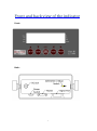
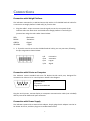
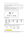
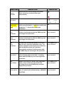
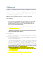
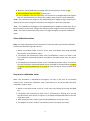
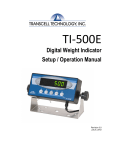
DWP-101
Digital Indicator
User’s Manual
Version 2011
www.digiweighusa.com
Front and back view of the indicator
Front:
Back:
1
Connections
Connection with Weigh Platform
The indicators mounted in an ABS enclosure ship with a 15 ft shielded load cell cable for
a connection to weigh platform’s load cell(s) or junction box.
1. Plug the cable’s 14-pin connector into the signal port on the rear panel of the
indicator. Wire the bare wires and shield to the weigh platform’s load cell(s) or
junction box using the color codes shown below:
RED:
BLACK:
GREEN:
YELLOW:
+Excitation
- Excitation
+Signal
- Signal
2. 2. If you do not wish to use the shielded load cell cable, you may use own, following
the pin assignments shown below:
1/8
3/10
5/12
7/14
+Excitation
-Excitation
+Signal
-Signal
Connection with Printer or Computer
The indicator comes standard with one full duplex RS-232 serial port, designed for
connection to either a PC or a serial printer. Below is the diagram:
2 Receive Data
3 Transmit
5 Signal Ground RS-232
Plug the serial printer, remote display or computer communication cable (not included)
directly into the D-SUB9 serial port connector.
Connection with Power Supply
The indicator comes with an external AC adapter. Simply plug the AC adapter into the its
DC Power Jack first, and then plug into a standard wall outlet.
2
Configuration
The indicator contains two main setup menus: The Setup (“H”) menu, which configures
the indicator to your weigh platform and the User (“A”) menu, which configures the
serial communication port and enables some user options. The Setup and User menus
consist of several menu selections, each with its own sub-menu of choices.
To set up the indicator, you must first enter the appropriate menu mode. Once there,
four of the front panel keys become directional navigators to move around in the menus,
and one key is used to save or SET the selections.
Set up H menu
1. Power off the indicator.
2. On the rear panel move the Calibration/Setup Switch to the opposite position.
3. Power on the indicator. The indicator shows ” H 1” to indicate that you are in Setup
H menu mode.
Use the directional keys to move around in the Setup Menu Chart.
1. To move to a new “H” heading, use the TARE (left) or PRINT (right) key to move right
or left in the Setup Menu Chart.
2. To move to the selection level, press the ZERO (down) key once. The current saved
selection is shown.
3. To view the available selections for the current “H” heading, use the TARE (left) or
PRINT (right) key to move through the selection field.
4. To save a new selection, press the NET/GROSS (Set) key .To exit without saving,
press the UNITS (up) key to return to the current “H” heading.
5. Repeat Steps 1 through 4 until the Setup Menu is programmed.
3
Setup Menu Chart
The User (“A”) menu sub-menus appear when scrolling left or right from the “H” menu.
Some selections shown are not available on some versions.
Exiting the setup menu
1. Power off the indicator.
2. On the rear panel, move the Setup/Calibration Switch back to its original position.
3. Power on the indicator. The display will go through a digit check then go into Normal
Operating mode. All front panel keys will now return to their normal mode of
operation.
USER (“A”) MENU
1. Enter the Setup (“H”) menu.
2. Use the right or left directional keys to move right or left in the Setup (“H”) menu until
the indicator shows ” A 1”.
4
Use the directional keys to move around in the User Menu Chart.
1. To move to a new “A” heading, use the TARE (left) or PRINT (right) key to move
right or left in the User Menu Chart.
2. To move to the selection level, press the ZERO (down) key once. The current saved
selection is shown.
3. To view the available selections for the current “A” heading, use the TARE (left) or
PRINT(right) key to move through the selection field.
4. To save a new selection, press the NET/GROSS (Set) key .To exit without saving,
press the UNITS (up) key to return to the current “A” heading.
5. Repeat Steps 2 through 5 until the User Menu is programmed.
SET
User Menu Chart
A1
Baud Rate
A2
Data Bits,Parity
8n
7O
7E
A3
Transmission Mode
7N
C
d
A4
Display Check
Press ZERO
key to begin
A5
Enable lb/kg Key
0
1
1200 2400 4800 9600
A6
Serial Port Mode
0
1
A7
ID No. Enable
0
1
A8
ID No. Entry
Press ZERO
key to begin
A9
No. of Line Feeds
Press ZERO
key to begin
Setup Menu Descriptions
This section provides more detailed descriptions of the selections found in the Setup
Menu Chart. Factory-set defaults are shown in bold with a checkmark (√).
5
NAME/CODE
DESCRIPTION
CODE/VALUE
H1
Graduation
Specifies number of full-scale graduations.
Value should be consistent with legal
requirements and environmental limits on the
useful system resolution.
500
1,000 1,500
2,000 2,500
3,000 4,000
5,000√ 6,000
8,000 10,000
12,000 20,000
30,000 40,000
50,000
H3
Zero Track
Band
Selects the range within which the scale will
automatically zero. Note that the scale must be
in standstill to automatically zero. Selections
are in Display Divisions.
0d
0.5d √
1d
3d
5d
H4
Zero Range
Selects the range which the scale may be
zeroed. Note that the indicator must be in
standstill to zero the scale.
Sets the level at which motion is detected by
H5
Motion Band comparing the present display update with the
previous one. If motion is not detected for two
seconds or more, scale is in standstill and can
process a Print or Zero command. Maximum
value varies depending on local regulations
H6
Digital Filter
100% √
1.90%
o.25d
1d
3d√
5d
10d
Averages weight readings to produce higher
stability. The higher the filter setting, the
stability but the slower the indicator's response
time. Choose SLO unless a very fast response
is needed.
Fast
H7
Overload
limit
Selects the desire formula which determines
the point at which the indicator shows overload.
All selections are based on the primary unit
selected in H8.
"FS"=Full
scale in primary units.
FS
FS+2%√
FS+1d
FS+9d
H8
Calib. Unit
Selects the primary base unit to be used in the
calibration process. Also the default unit for
normal operation.
1√
2
"1"=primary unit is lb.
"2"=primary unit is kg
6
Nned
slo√
NAME/CODE
H9
Display
Divisions
DESCRIPTION
Determines the desired weight increments.
Value should be consistent with legal
requirements.
CODE/VALUE
1√
2
3 5
H10
Decimal Pt.
H15
Span Calib.
Type
0 √
0.00
0.0000
Selects the Span Calibration type. 1 -one time
1√
calib in the graduation. 2 - two times calib in the 2
graduation. 3 - three times calib in the
3
Determines location of the decimal point.
0.0
0.000
00
graduation.
H16
Zero
Calibration
H17
Span
Calibration
H18
View
Calibration
H19
Key-in Zero
H20
Key-in Span
H21
Factory Reset
Places indicator into the zero calibration
routine. Scrolling down with the ZERO key one
level begins the procedure.
Press ZERO key to
Places indicator into the span calibration
routine. Scrolling down with the ZERO key one
level begins the procedure.
Press ZERO key to
Actuates the function that allows you to view
both the zero and span calibration value. The
values displayed in this function are valid only
after Calibration (H16 & H17) has been
successfully completed. Scrolling down with
the ZERO key one level begins the procedure.
Press ZERO key to
Allows you to key-in zero calibration value in
case of memory loss in the field. Scrolling
down with the ZERO key one level begins the
procedure.
Press ZERO key to
Allows you to key-in a known span calibration
value in case of memory loss in the field.
Scrolling down with the ZERO key one level
begins the procedure.
Press ZERO key to
begin sequence
begin sequence
begin sequence
begin sequence
begin sequence
Press ZERO key to
This sub-menu will reset parameters in the "H"
and "A" menu to the default settings. USE WITH begin sequence
CAUTION!
7
User Menu Descriptions
This section provides more detailed descriptions of the selections found in the
User Menu Chart. Factory-set defaults are shown in bold with a checkmark (√).
8
NAME/CODE
DESCRIPTION
CODE/VALUE
A1
Baud Rate
Selects the baud rate for data transmission through the
serial port.
1200
2400 4800
9600√
19200
A2
Data Bits and
Parity
Selects the number of data bits and parity of serial
transmission.
"8n"=8 data bits with no
parity bit and one stop bit.
"7O"=7 data bits with odd parity bit and one stop bit.
"7E"=7 data bits with even parity bit and one stop bit.
"7n"=7 data bits with no parity bit and two stop bits
8n√
7O
7E
7n
A3
Mode of
Serial
Transmission
Selects when data will be sent out of the serial port to a
printer or computer.
"C" = Continuous mode; send data continuously
"d" = Demand mode; send data when a PRINT
command is issued from the printer, computer, or
indicator.
A4
Display
Check
Actuates the function that illuminates all digit segments,
decimal points, and LCD annunciators in a test
sequence. Pressing the ZERO key to scroll down one
level begins the test sequence.
Press ZERO key
A5
Disable the
lb/kg Key
Allows the lb/kg key to be disabled so that an operator
cannot accidentally press the key and change the
display units.
"0" = Disable the lb/kg key
"1" = Enable the lb/kg
key
0
1√
9
C
d√
to begin
sequence
NAME/CODE
DESCRIPTION
CODE/VALUE
A6
Serial Port
Mode
Select the mode of the RS-232 serial port;
"0" = Full Duplex Mode
"1" = Print Ticket Mode
0
A7
ID No.
Enable
Allows the ID number to be disabled in the Print Ticket
mode. Valid only when A6 is set to "1".
"0" = Disable the ID No.
"1" = Enable the ID No.
0√
1
A8
ID No. Entry
Actuates the function that allows entry of a new ID No.
0-9999994
Valid only when A6 is set to "1". Pressing the ZERO key 123456√
to scroll down one level begins the test sequence.
A9
No. of Line
Feeds
Actuates the function that allows entry of number of line 0-99
feeds to be printed in Print Ticket Mode. Valid only when 8√
A6 is set to "1". Pressing the ZERO key to scroll down
one level begins the test sequence.
Enables hardware handshaking for Ticket Mode. Valid
A10
Handshaking only when A6 is set to "1".
"0" = Disable Handshaking
"1" = Enable
Enable
1√
0√
1
Handshaking
A11
Print Header
To print the header information. Valid only when A6 is
set to "1".
"0" = Disable the ID No.
"1" = Enable the ID No.
0√
1
10
Calibration
The indicator is calibrated by following the procedures embedded in H16 (Zero) and H17
(Span) of the Setup Menu. Each procedure enters a value into the indicator's
non-volatile memory -H16 the zero value (deadweight) and H17 the span value (test
weight). The minimum test weight that can be used is 1% of full-scale capacity. After the
two calibration procedures are executed successfully, you should record both calibration
values in Table 6-1 using the H18 View procedure.
NOTE: This chapter assumes that the indicator is in Setup (“H”) Menu mode.
Zero Calibration
1 While in the Setup mode, scroll to "H 16", then scroll down once using the ZERO
key to enter zero calibration menu. The display will momentarily show "C 0"
followed by a value. This value is the internal A/D count and can prove useful
when trying to troubleshoot setup problems.
2 After making sure that there are no test weights on the platform, press the ZERO
key again to zero out the displayed value.
3 Waiting for about 30 seconds. Press the NET/GROSS key to save the zero point
value. The display will show "EndC0"
4 momentarily, then revert back up to H16. At this time, proceed to the H17 span
calibration to complete indicator calibration.
Span Calibration
The indicator has three types in span calibration that can improve the indicator’s
ability to meet the multi-graduation .
1. While in the Setup mode, scroll to "H 17", then scroll down once using the ZERO
key to enter span calibration menu.
2. The display will momentarily show "C 1" for the span calibration, followed by a
value with one flashing digit. This value will be zero with the Decimal Point
parameter selected in H10. Place the test weight on the weighing mechanism.
3. Use the four directional keys to adjust the displayed value to the actual test weight
value. Increase the flashing digit by pressing the UNITS key. Decrease the flashing
digit by pressing the ZERO key. Pressing the PRINT key or the TARE key will change
the position of the flashing digit. Setting the exact value
4. Waiting for about 30 seconds., press the NET/GROSS key to save the value.
5. If the calibration was successful, and H15=2, the display will show "EndC1"
momentarily, then go to “C2”
6. Repeat 2-4 using different test weight value .
7. If H15=3, the display will show “EndC2” momentarily, the go to “C3”.
11
8. Repeat 2-4 using different test weight value and End C3 then revert to H17.
9. If the calibration was successful, revert to H17.
10. If the calibration was not successful, one of the error messages below will appear.
Take the indicated action to correct the problem then perform a new calibration.
"Err0" -The calibration test weight or the adjusted keyed-in weight is larger than the full
capacity of the scale. Change the calibration test weight or check the input data.
"Err1" -The calibration test weight or the adjusted keyed-in weight is smaller than 1% of
the full capacity of the scale. Change the calibration test weight or check the input data.
"Err2" -The internal resolution of the scale is not high enough to accept the calibration
value.
View calibration values
Note: The values displayed in this procedure are valid only after a successful calibration
has been performed using H16 and H17.
1. While in the Setup mode, scroll to "H 18", then scroll down once using the ZERO
key to enter view calibration menu.
2. The display will momentarily show "CAL 0" followed by a value. This value is the
zero calibration value and should be recorded in the table below. Press any key to
continue.
3. The display will momentarily show "CAL 1" followed by another value. This value is
the span calibration value and should also be recorded in the table below. if H15=2
or H15=3,it can also show “CAL 2” or “CAL 3”. Press any key to return to upper level
(H18).
Key-in zero calibration value
Note: This procedure is intended for emergency use only in the case of non-volatile
memory loss. A valid zero calibration value, obtained from a successful H16 calibration
procedure, must be used.
1. While in the Setup mode, scroll to "H 19" then scroll down once using the ZERO
key.
2. The display will momentarily show "CAL 0", followed by a flashing zero. Use the
four directional keys (shown in Figure 6-1) to adjust the displayed value to the zero
calibration value.
3. After setting the exact value, press the NET/GROSS key to save the value.
4. The display will show "E CAL 0" momentarily then revert back up to H19.
12
Key-in span calibration value
Note: This procedure is intended for emergency use only in the case of non-volatile
memory loss. A valid span calibration value, obtained from a successful H17 calibration
procedure, must be used.
1. While in the Setup mode, scroll to "H 20", then scroll down once using the ZERO key.
2. The display will momentarily show "CAL 1", followed by a flashing zero. Use the four
directional keys (shown in Figure 6-1) to adjust the displayed value to the span
calibration value.
3. After setting the exact value, press the NET/GROSS key to save the value. If H15=2 or
H15=3, the display will also show “CAL 2” or “CAL 3”, the two parameters can be set
too.
4. If the entered value is greater than zero, the display will show "E CAL 1" momentarily
then revert back up to H20. If a value of zero is entered, the indicator will briefly
show "Err 5" then revert back to the screen described above in Step # 2.
13
Operation
Display
Display Details
Keyboard
Units – This key toggles the indicator among the available weight units if enabled in the
User (“A”) menu. Available weight units include lb and kg.
Zero -This key sets the indicator to display zero provided the following conditions are
met:
1
The indicator is displaying Gross weight.
2
The displayed weight is within the zero reset range that is programmed in H4 of
the Setup (“H”) Menu.
3
The scale is not in motion or in overload.
Net/Gross -This key toggles the indicator between Gross weight and Net weight only if
a Tare has been established.
14
Tare -This key is used to establish a Tare provided the following conditions are met:
1 The indicator is not at or below Gross zero.
2 The scale is not in motion or overload.
Print -This key is used to send weight information out to the serial port provided the
scale is not in motion or overload.
Weighing
1
2
3
4
Select the desired weighing unit by pressing the lb/kg key until that unit is
indicated on the display.
If necessary, press the ZERO key to obtain a weight reading of zero.
Place the object to be weighed on the scale’s platter and allow the weight
indication to Stabilize. If the item weight exceeds the scale’s weight capacity, it
displays “❐❐❐❐❐❐”.
Read the weight shown on the display.
Tare Function
To weigh an item in a container, the weight of that container must first be subtracted
from the overall weight to obtain an accurate weight reading. This is known as taring.
1 Select the desired weighing unit by pressing the lb/kg key until that unit is
indicated on the display.
2 If necessary, press the ZERO key to obtain a weight reading of zero.
3 Place the empty container on the scale’s platter and allow the weight indication
to stabilize.
4 Press the TARE key. The display shows zero weight and turns the NET indication
on.
5 Place the material to be weighed in the container and allow the weight
indication to stabilize.
6 Read the weight shown on the display.
7 You may toggle between the gross weight and the net weight by pressing the
NET/GROSS key.
15
Appendix A
Error information:
display
mode
description
□□□□□□
weighing mode
overload or without ADC input
ERR0
H17 Span Calib.
The calibration test weight or the
adjusted keyed-in weight is larger
than the full capacity of the scale.
Change the calibration test weight
or check the input data.
ERR1
H17 Span Calib.
The calibration test weight or the
adjusted keyed-in weight is smaller
than 1% of the full capacity of the
scale. Change the calibration test
weight or check the input data.
ERR2
H17 Span Calib.
The internal resolution of the scale
is not high enough to accept the
calibration value.
ERR3
ERR4
all modes
One or more parameters had lost.
all modes
Rom writing wrong. The indicator
needs to repair.
ERR5
H20 Key-in Span Calib.
If a value of zero is entered, the
indicator will briefly show "Err 5".
ERR9
weighing mode
The
span
calib.parameters
had
been lost. The indicator needs to
reset H17.
16