1
10.5 Safety Check
In the event of an electrical fault after the installation of the
appliance, the electrical system shall be checked for short
circuits, fuse failure or incorrect polarity of connections.
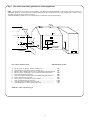
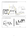
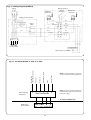
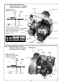
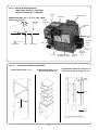
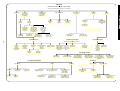
10.6 Pre-wired Remote Y Plan or S Plan System
(See Fig.13).
If the system is fully pre-wired at a junction box remotely from
the boiler it can be connected to the boiler. The diagram showsconnection details of two popular proprietary systems
(Honeywell and Invensys), for these and other systems from
other manufacturers always use the boiler instructions in conjunction with the system instructions..
10. Electrical
(See Figs. 11 to 13).
10.1 The wiring between the appliance and the electrical supply
shall comply with current IEE Wiring Regulations (and any local
regulations which apply) for fixed wiring to a stationary appliance.
The method of connection must allow complete isolation of the
appliance and the supply to the boiler must be the only electrical
supply to the system. This ensures the safety of a single fused
supply.
10.7 Frost Protection
The appliance is supplied with a frost thermostat with the phial
positioned within the boiler casing, this protects the boiler only.
For full frost protection of the property and/or system a frost
thermostat should be fitted so that both the boiler and the
circulating pump circuits are energised under frost
conditions.
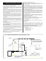
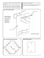
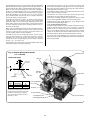
Outdoor Pack control box (See Fig. 3)
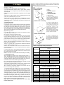
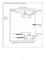
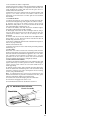
A service switch has been provided to allow the service engineer
to service the appliance from outside the property (See Fig.11) .
NOTE: The appliance provides a permanent external electrical
supply for servicing and should therefore be fed via a circuit
breaker including earth leakage protection.
10.2 To gain access to the electrical terminal strip.
1.
Isolate the mains electrical supply from within the
property
2.
Remove the Outdoor Pack front cover by undoing the two
handwheels on the door and padlock if fitted. Pull forwards
at the top of the panel and lift the front cover to release
from the locating tabs on the base.
3.
Remove the boiler front panel by pulling forwards to
release the ball studs.
4.
Pull the thermostat control knob forwards to remove
from its spindle.
5.
Undo the facia retaining screws and remove the plate.
The engineer should have access to the property to set the
heating system controls to give a central heating demand so
that heat generated during the burner testing can be dissipated.
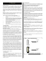
The switch settings are:
'Run' Mode -The boiler is controlled by the programmer. There
is power to the 3-pin trailing socket allowing the use of a light in
low light conditions.
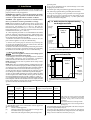
10.3 Mains Wiring
Mains supply - 230 V AC ~ 50 Hz 5A External Fuse to BS1362.
SWITCHED LIVE - Black, NEUTRAL - Blue, EARTH - Green/Yellow,
PERMANENT LIVE-Brown
Mains Cable: 0.75mm2 (24 x 0.20mm) to BS 6500 Table 16.
The supply to the boiler must be the only electrical supply to the
system. This ensures the safety of a single fused supply.
The mains supply four core cable should be connected into the
terminals marked Perm L (Permanent Live), Switch L (Switched
Live), N (Neutral) and E (Earth) on the outdoor control box
terminal strip and securely held in the cable clamp located in the
left-hand side of the outdoor control box.
To secure the cable, remove the clamp retaining screws and lift its
top section up to allow the cable to be fed through. With the cable
in position refit the two screws and fully tighten to grip the cable.
Feed the cable between the side panel and the boiler insulation
jacket to the back of the boiler. Avoid any hot surface and route
through the open/close bush provided on the open side panel of
the Outdoor Pack. Once the cable is outside the Outdoor Pack it
should be protected by conduit until inside the property.
'Service' Mode- There is no power to the boiler but there is
power to the 3-pin trailing socket allowing the use of a light or
vacuum cleaner for servicing purposes.
NOTE: To isolate mains supply to the appliance (including the
Outdoor Pack control box) switch off the supply inside the
property
After serving the appliance the Service engineer must leave the
appliance in the 'run' mode.
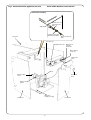
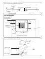
Fig. 11. Service Switch Positions
Service Switch
in
'Run'
Mode
The mains supply three core cable from the Outdoor Pack
control box should be connected into the terminals marked L
(Live), N (Neutral) and E (Earth) on the boiler terminal strip and
securely held in the cable clamp located in the right-hand side of
the electrical tray base. To secure the cable, remove the clamp
retaining screw and pull its inner body out to allow the cable to
be fed through. With the cable in position refit the screw and
fully tighten to grip the cable. The cable clamp on the
Danesmoor Utility (12/14, 15/19 and 20/25) and the Worcester
Bosch (50/70 and 70/90) should be moved to the alternative
position on the right hand side of the boiler electrical control box
Service Switch
in
'Service'
Mode
The appliance must be earthed.
10.4 Programmer
A time clock or programmer may be added to the control
system. A two channel programmer will allow independent
control of the central heating and hot water.
NOTE: Under no circumstances should the timer be connected to
a separate electrical supply. Safety is assured from a single fused
supply to the boiler.
NOTE: ALWAYS SET THE SWITCH TO 'RUN' AFTER SERVICING
13