1
while holding the burner in a vertical position, fill the nozzle holder
with oil and refit the nozzle. Replace the burner and continue to
run the boiler for three minute periods until after-spurting stops.
Note: In order that after-spurting is reduced to a minimum
during the commissioning period it is recommended that a
pressure gauge only is fitted on the external pressure gauge port
on the Electro Oil B11 (See Fig.30). Use of a “T” piece pressure
gauge manifold will increase the oil line volume and hence
increase the degree of after-spurting.
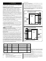
12.12 Run the boiler for a further 15 minute period and then
finally fine tune the air shutter setting to give the CO2 level
specified in Tables 2 to 5 less 0.5%CO . During this period some
smoke will be emitted due to the burning of the organic binder in
the base insulation board. Smoke readings will therefore be
inaccurate at this point.
Note: A flue gas sampling point is located on the boiler top plate.
12.13 Check that the smoke reading is in the range 0-1. If this
cannot be achieved then check that the burner head is set
correctly and the nozzle is in good condition.
12.14 Check that the flue temperature does not exceed the
value specified in Tables 2 to 5. If this is the case then check that
the baffles are correctly located. If the baffles are correctly
located then reduce the pump pressure since nozzle variations
of up to + or – 15% may occur.
12.15 Remove the oil pressure gauge and manifold and check
all oil system joints for any signs of leakage.
12.16 Allow the burner to run for a further five minutes and
then recheck the CO2 level and adjust the air setting if required.
Check that the smoke number is in the range 0-1. Repeat the fine
tuning procedure if found necessary.
12.17 Refit the boiler cabinet top and front panels in the reverse
order to that described in Section 5.
12.18 When the heating circuit has reached full operating
temperature check the whole system for any leaks.
12.19 Locate and fully tighten the top panel to the brace with
the two screws provided ensuring it sits on the side panels..
12.20 Locate the front panel and tighten to the Outdoor Pack
using the two handwheels provided.
12.21 Locking the Outdoor Pack
Provision has been made to lock the outdoor front panel using a
padlock underneath the front of the top panel. A suitable
padlock is the P73 manufactured by Yale Security Products, or
the use of a Padlock which has 20 to 22 mm between the two
centres on the shackle and 15mm to 20mm between the inside
of the body and the shackle and a shackle diameter of 5mm.
For the Security of the Outdoor Pack ensure the top panel is
siting on the side panels and fully tightened to the brace with the
two screws provided.
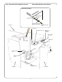
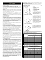
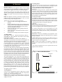
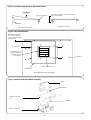
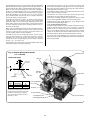
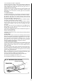
Fig. 28. Electro Oil Inter B9A Burner.
(12/14 model)
Combustion Head
Photocell
2mm
A
Combustion head
Spark gap
2 -2.5 mm
10mm
Adjusting
disc
Draught tube
Transformer
Nozzle block
Nozzle
Output
Dimension
kW
Head Type
A
12
PL 6/7/21.5/10-E
3 mm
14
PL 6/7/21.5/10-E
5 mm
To adjust the nozzle position, undo the
locking screw located at the rear of the
nozzle line and rotate the adjusting
disc one turn anti-clockwise to move
forward by 1 mm.
Pressure Adjustment
Screw
Control box
Oil pump
Air control indicator
Air adjustment screw
(4mm hexagonal head)
23
Lockout reset button