1
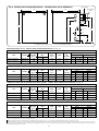
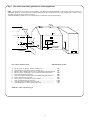
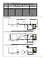
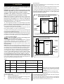
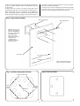
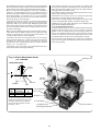
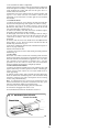
Fig. 2. Outdoor Pack Principal Dimensions. (All Dimensions are in millimetres)
670
Flue terminal
Flue terminal
guard
760
212
267
740
975
68
X
798
148
238
142
X= 806 (26/32 and 90/110)
X= 811 (on all other models)
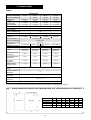
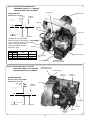
Danesmoor Utility 12/14 Table 2. Electro Oil Inter B9A Burner (See Fig. 29)
NOMINAL BOILER RATING AT NORMAL OPERATING TEMPERATURE
Fuel
28 Sec. Kerosene
28 Sec. Kerosene
Nozzle
Pump
Pressure
(p.s.i.)
0.40 60°ES
0.50 60°ES
130
100
Fuel Flow
Rate
Kg/h
l/h
1.11
1.41
1.30
1.64
Flue Gas
Temp.
(°C)**
180
195
%CO2
10
11.5
Approx.
Air
Setting
6.0
7.0
Appliance
Input
Output
kW
Btu/hr
kW
Btu/hr
13.5 46,000
12
41,000
15.5 53,000
14
48,000
Danesmoor Utility 15/19 and Worcester Bosch 50/70
Table 3. Electro Oil Inter B9B Burner (See Fig. 30)
NOMINAL BOILER RATING AT NORMAL OPERATING TEMPERATURE
Fuel
28 Sec. Kerosene
28 Sec. Kerosene
28 Sec. Kerosene
Nozzle
Pump
Pressure
(p.s.i.)
0.50 60°ES
0.55 80°EH
0.60 60°ES
110
115
105
Fuel Flow
Rate
Kg/h
l/h
1.40
1.77
1.59
2.01
1.78
2.25
Flue Gas
Temp.
(°C)**
215
225
235
%CO2
10.5
10.5
11.5
Approx.
Air
Setting
8.5
8.75
9.0
kW
17
19
21.5
Appliance
Input
Output
Btu/hr
kW
Btu/hr
58,000
15
51,000
65,000
17
58,000
73,000
19
65,000
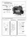
Danesmoor Utility 20/25 and Worcester Bosch 70/90 Table 4. Electro Oil Inter B11C Burner (See Fig. 31)
NOMINAL BOILER RATING AT NORMAL OPERATING TEMPERATURE
Fuel
28 Sec. Kerosene
28 Sec. Kerosene
28 Sec. Kerosene
Nozzle
0.60 80°EH
0.75 80°EH
0.75 80°EH
Pump
Pressure
(p.s.i.)
130
105
130
Fuel Flow
Rate
Kg/h
l/h
1.87 2.37
2.10 2.66
2.34 2.96
Flue Gas
Temp.
(°C)**
190
205
220
%CO2
11.0-11.5
11.5-12.0
12.0-12.5
Approx.
Air
Setting
5.5
6.0
6.5
kW
22.5
25
28
Appliance
Input
Output
Btu/hr
kW
Btu/hr
77,000
20
68,000
86,000
22.5
77,000
96,000
25
85,000
Danesmoor Utility 26/32 and Worcester Bosch 90/110 Table 5. Electro Oil Sterling 40 Burner (See Fig. 32)
NOMINAL BOILER RATING AT NORMAL OPERATING TEMPERATURE
Fuel
28 Sec. Kerosene
28 Sec. Kerosene
28 Sec. Kerosene
Nozzle
Pump
Pressure
(p.s.i.)
0.85 80°EH
0.85 80°EH
1.00 80°EH
110
130
130
Fuel Flow
Rate
Kg/h
l/h
2.36
2.99
2.66
3.37
2.95
3.74
Flue Gas
Temp.
(°C)**
225
240
245
%CO2
11.0-11.5
11.0-11.5
11.5-12.0
Approx.
Air
Setting
11
12
16
kW
28.5
32
35.5
Appliance
Input
Output
Btu/hr
kW
Btu/hr
97,000
26
89,000
109,000
29
99,000
121,000
32
109,000
** NOTE: The flue gas temperature is measured in the gas sampling hole on the flue outlet plate. The probe should be inserted to a depth of 50mm and angled towards the flue outlet. The temperature measured is not an
absolute flue gas temperature and is for general guidance purposes only!
NOTE: The pump pressure given is for general guidance only as variations in nozzle output can be up to ± 15%. It is, therefore, essential that the air is adjusted to give the correct CO2 value.
NOTE: The nozzle type used on 28 Sec. Kerosene outputs are nozzles calibrated specifically for use with 28 Sec. Kerosene which gives less variation in nozzle output than the standard 35 Sec. Gas Oil nozzles. However, if a 28
Sec. Kerosene nozzle is not available at servicing or commissioning it is appropriate to install a 35 Sec. Gas Oil nozzle providing the output, spray angle and pattern of the nozzle is the same as the 28 Sec. Kerosene nozzle (e.g.
0.75 80°EH may be replaced with a 0.75 80°H).
4