1
Analytical Modules, continued
Replacement Thermistor
Wiring Harness
Step
Procedure
1.
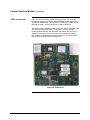
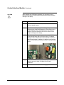
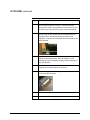
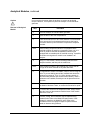
Making note of the connection location for each wire, remove
the wiring that is connected to the Thermistor/Filament Board
that is to be removed. Remove the wires by carefully pulling on
the end of the metal connector.
2.
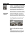
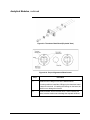
Remove the wiring harness by removing the 2 mm button head
hex screws that secure the 9-pin connector to the manifold.
3.
Install the new wiring harness using the 2 mm button head hex
screws.
4.
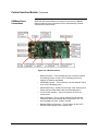
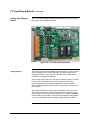
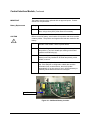
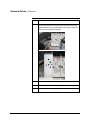
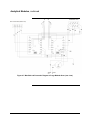
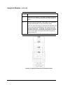
Reconnect wiring to the thermistor boards. Wiring MUST be
connected to the same cells as before. Verify all termination
points.
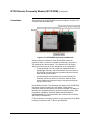
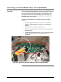
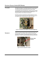
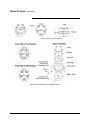
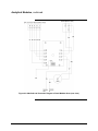
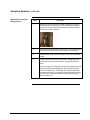
Note: The length of the wiring is such that color coded wires can
connect only to their specified bead. Also note that there are
two wires of each color. Technically, for a specific cell it does
not matter which wire is connected to which lead as long as the
color is correct. However, the wires should be connected as
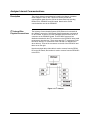
shown in figure 4-11.
A5E31405710001
4-35