1
Model 50 Valve, Continued
Maintenance
Procedures
Valve Removal and
Disassembly
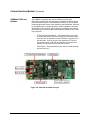
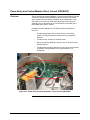
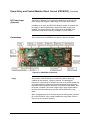
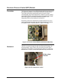
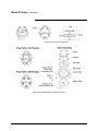
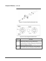
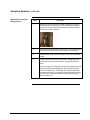
(see Figure 4-5)
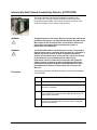
The valve is serviced by disassembling and then thoroughly cleaning the
components to remove all particulates. Ultrasonic cleansing with a
suitable solvent works very well. During the cleaning and re-assembly
process, care must be taken to avoid scratching or damaging the
polished surfaces of the valve. After cleaning, the valve is
reassembled using new Teflon® coated stainless steel diaphragms. DO
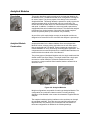
NOT attempt to reuse old diaphragms. Notice the alignment marks on
the three sections of the valve near the actuation ports. The valve should
be reassembled so that these marks line up. If the marks do not line up it
is possible that the center plate is upside down. The screws should be
tightened evenly to 6-8 inch pounds using the appropriate torque
screwdriver with an Allen head bit.
Step
Procedure
1.
Remove the Analytical Module from the Oven as described in
the Analytical Module section of this chapter. It is not required
to power off the analyzer or remove power to the oven.
2.
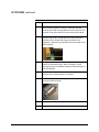
Once the Analytical Module is removed, to remove Model 50
Valve from the module, first disconnect all tubing connected to
the valve.
CAUTION
When disconnecting Valco fastening nuts from Model 50 Valve, exercise
caution not to bend or crimp the stainless steel tubing.
NOTE
Before removing Model 50 Valve from module make note of its
orientation on the module.
CAUTION
4-22
3.
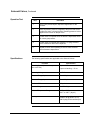
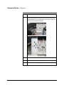
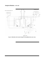
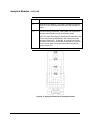
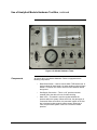
Remove the valve from the oven by unscrewing the two M3 x 35
socket head cap screws securing the Model 50 Valve. These
mounting screws are located between ports 2 and 3 and ports 8
and 9. Refer to Figure 4-5 for port locations.
4.
Place the valve on a clean dust and lint free cloth within a clean
work environment.
Do not place polished top plate, center plate or bottom plate against any
abrasive surface. Place components on a lint free cloth free of foreign
contaminants.
A5E31405710001