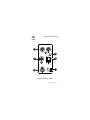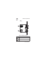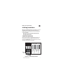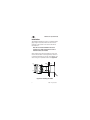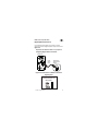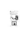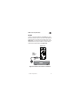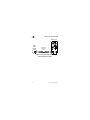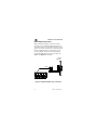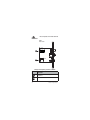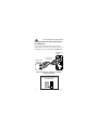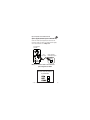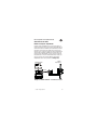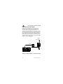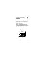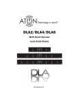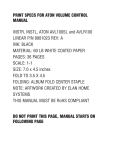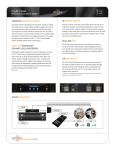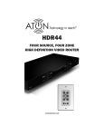
1
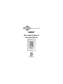
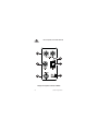
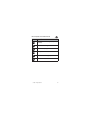
DHSIP
SOURCE INPUT
WALL PLATE
www.atonhome.com
DHSIP Source Input Wall Plate
Safety Information
NOTE: This equipment has been tested and found to comply with the
limits for a Class B digital device, pursuant to part 15 of the FCC Rules.
These limits are designed to provide reasonable protection against
harmful interference in a residential installation. This equipment generates, uses and can radiate radio frequency energy and, if not in-stalled
and used in accordance with the instructions, may cause harmful
interference to radio communications. However, there is no guarantee
that interference will not occur in a particular installation.
If this equipment does cause harmful interference to radio or television
reception, which can be determined by turning the equipment off and
on, the user is encouraged to try to correct the interference by one or
more of the following measures:
• Reorient or relocate the receiving antenna.
• Increase the separation between the equipment and receiver.
• Connect the equipment into an outlet on a circuit different from
that to which the receiver is connected.
• Consult the dealer or an experienced radio/TV technician for help.
CAUTION: Changes or modifications not expressly approved by ATON
could void the user’s authority to operate the equipment
Clean only with a dry soft cloth.
It is important to properly care for your DHSIP. Follow these guidelines
to ensure your device is preserved and protected.
• Do not expose the DHSIP to rain, liquids or moisture for an
extended period of time.
• Do not expose the DHSIP to temperature extremes.
Operating Temperatures & Environments
• Operating Temperature: 32-104°F (0-40° C)
• Humidity: 0-90%
© 2008 • All rights reserved.
1
DHSIP Source Input Wall Plate
Precautions
• Always exercise care when operating a system utilizing the DHSIP.
• Do not install near any heat sources such as radiators, heat reg
isters, stoves, or other apparatus (including amplifiers)
that produce heat.
• In the unlikely event that smoke, abnormal noise, or strange odor
is present, immediately power the DH44 or DH46X Digital Audio
Router that the DHSIP is connected to off. Please report
the problem to your dealer immediately.
• Never attempt to disassemble the DHSIP. You will lose any product
warranty on the unit.
Package Contents
•
•
•
•
2
DHSIP Source Input Wall Plate
Trim Ring
Mounting Screws
Installation Manual
©2008 • All rights reserved.
DHSIP Source Input Wall Plate
1. Introduction
The DHSIP Source Input Wall Plate allows a Local
Source (a source located within a room and not available to the DH44 Digital Audio Router system as a
whole) to easily connect to a DHTP1 Amplified Touch
Pad. It also serves as a source input wall plate for the
DH46X Digital Audio Router in stand-alone applications. The DHSIP provides connections for Analog
Audio, Digital Optical Audio, Digital Coaxial Audio and
IR Control.
Features
• Local Source Wall Plate for DHTP1 Amplified
Touch Pads
• Source Input Wall Plate for DH46X Digital Audio
Router
• Accepts Analog Audio, Digital Optical Audio,
Digital Coaxial Audio
• Converts Analog Audio to Digital
• 3-Position Source Input Selection Switch
• Clipping Indicator
• Gain Adjustment
• IR Output Jack for Source Control
• Rear RJ-45 Jack for Cat-5 Connection to
DHTP1 Amplified Touch Pad or DH46X
© 2008 • All rights reserved.
3
DHSIP Source Input Wall Plate
Front
1
6
2
5
3
4
Figure 1.1: DHSIP Front Callout
4
©2008 • All rights reserved.
DHSIP Source Input Wall Plate
Function
1
Analog Audio Input (L/R)
2
Digital Coaxial Audio Input
3
IR Output
4
Source Input Switch
5
Digital Optical Audio Input
6
Clipping Indicator LED
© 2008 • All rights reserved.
5
DHSIP Source Input Wall Plate
Rear
DHSIP
Side View
GAIN
R
1
L
+4 +8 +4 +8
O1 2 3 4
N
2
Figure 1.2: DHSIP Rear Callout
Function
6
1
Gain Adjustment DIP Switches
2
Output RJ-45 Connector
©2008 • All rights reserved.
DHSIP Source Input Wall Plate
2. Wiring/Installation
Wiring for the DHSIP consists of a single run of Cat-5
wire between the DHTP1 Amplified Touch Pad or
DH46X Digital Audio Router and the mounting location for the DHSIP.
Note: Do not run Cat-5 wires closer than 12"
from high voltage wires.
T-568A Wiring Standard
All Cat-5 connections in a DH44-based system use
the industry standard T-568A wiring scheme as illustrated in Figure 2.1. RJ-45 connectors are used to
terminate Cat-5 wires at both ends.
1 2 3 4 5 6 7 8
BROWN/WHITE
BROWN
BLUE/WHITE
ORANGE
ORANGE/WHITE
BLUE
Shown tab
down
GREEN/WHITE
GREEN
1 2 3 4 5 6 78
Figure 2.1: T-568A Wiring Standard
© 2008 • All rights reserved.
7
DHSIP Source Input Wall Plate
Installation
The DHSIP is designed to mount in a standard singlegang rough-in box (J Box). Mount the unit in close
proximity to the location of the source that will be
connected to it.
Note: Do not mount the DHSIP in the same
rough-in box as high voltage devices such as
electrical outlets or switches.
After running Cat-5 and terminating the ends, route
the wire into the back of the rough-in box, connect it
to the RJ-45 connector on the rear of the DHSIP, and
mount using the 2 provided screws. See Figure 2.2.
Screw
Screw
Rough-In
Box
Stud
DHSIP
Screw
Screw
Cat-5
Figure 2.2: Installing the DHSIP
8
©2008 • All rights reserved.
DHSIP Source Input Wall Plate
3. Connections
Connections for the DHSIP consists of:
1. Source Connections - Front
2. DHTP1 Amplified Touch Pad Connections - Rear
3. DH46X Digital Audio Router - Rear
Source Connections
Sources are connected to the DHSIP in one of three
ways:
1. Analog
2. Digital Coaxial
3. Digital Optical
For best sound quality, use one of the Digital connection methods if the Source has this type of output.
For sources that do not have Digital outputs, use the
Analog option.
Note 1: Make sure that the DHSIP’s Source Input
Switch is correctly set for the type of connection used.
Note 2: Multi-channel digital audio formats (5.1, 7.1,
etc.) are not supported by the DHSIP. Most audio/video
sources allow you to change the digital output to PCM
Stereo. In most cases, this will allow multi-channel audio sources to output a “summed” stereo signal through
the digital output. Consult the audio/video source
manual for details.
Note 3: Some audio sources which utilize a digital
output require that you enable the digital output before
it will function. If there is no audio present, check the
setup menu of the audio source to confirm that the
digital output is enabled.
© 2008 • All rights reserved.
9
DHSIP Source Input Wall Plate
Analog (AUDIO IN L/R)
Use RCA audio patch cables to connect an audio
source that does not have a Digital output as shown
in Figure 3.1.
DHSIP Front
Stereo
RCA Patch
Cables
Audio Source
Analog Output
L
R
Figure 3.1: Audio Source to DHSIP Connections
Analog
Set the RCA/OPT/COAX
Selection Switch to the
RCA position.
10
©2008 • All rights reserved.
DHSIP Source Input Wall Plate
Digital Optical (OPTICAL IN)
Use a Digital Optical Cable to connect an audio
source that hase a Digital Optical output as shown in
Figure 3.2.
Important: See Note 2 & Note 3 on p.9 prior to
configuring Digital Audio connections.
DHSIP Front
Digital
Optical
Cable
Audio Source
Digital Optical
Output
DIGITAL
OPTICAL
Figure 3.2: Audio Source to DHSIP Connections
Digital Optical
Set the RCA/OPT/COAX
Selection Switch to the
OPT position.
© 2008 • All rights reserved.
11
DHSIP Source Input Wall Plate
Digital Coaxial (COAX IN)
Use a Digital Coaxial Cable to connect an audio
source that has a Digital Coaxial output as shown in
Figure 3.3.
Important: See Note 2 & Note 3 on p.9 prior to
configuring Digital Audio connections.
DHSIP Front
Audio Source
Digital Coaxial
Output
DIG
COAX
Digital
Coaxial
Cable
Figure 3.3: Audio Source to DHSIP
Connections - Digital Coaxial
Set the RCA/OPT/COAX
Selection Switch to the
COAX position.
12
©2008 • All rights reserved.
DHSIP Source Input Wall Plate
IR OUT
Connect a standard IR Emitter (ATON AIE2, for example) from the IR OUT port on the front of the DHSIP to
the IR receiver on the front of the audio source (see
Figure 3.4). For sources that have an IR Input port on
the back of the unit, use a 3.5mm to 3.5mm mono
interconnect cable instead (see Figure 3.5).
DHSIP Front
AIE2
Talk-Back
Emitter
CD
Figure 3.4: IR OUT to Local Source - IR Emitter
© 2008 • All rights reserved.
13
DHSIP Source Input Wall Plate
DHSIP Front
Audio
Source
IR Input
IR IN
3.5mm Mono
Interconnect
Cable
Figure 3.5: IR OUT to Audio Source
3.5mm Interconnect Cable
14
©2008 • All rights reserved.
DHSIP Source Input Wall Plate
Rear Connections
DHTP1 Amplified Touch Pad
When utilizing the DHSIP as a means to connect a
Local Source to a specific zone of a DH44-based
system, rear connections consists of plugging in a
Cat-5 wire terminated to an RJ-45 connector wired
to T-568A standard to the RJ-45 jack on the rear of
the DHSIP. The other end simply plugs into the LOCAL
PORT RJ-45 jack on the rear of the zone’s DHTP1
Amplified Touch Pad. See Figure 3.6 for details.
DHSIP
Vista Lateral
DHTP1 Posterior
Cat-5
Figure 3.6: DHSIP to DHTP1 - Rear Connections
© 2008 • All rights reserved.
15
DHSIP Source Input Wall Plate
DH46X Digital Audio Router
When utilizing the DHSIP as a means to connect
an audio source to a DH46X Digital Audio Router in
Stand-Alone mode, rear connections consists of plugging in a Cat-5 wire terminated to an RJ-45 connector
wired to T-568A standard to the RJ-45 jack on the
rear of the DHSIP. The other end simply plugs into
the SOURCE LOOP IN RJ-45 jack on the rear of the
DH46X. See Figure 3.7 for details.
DHSIP
Side View
Cat-5
DH46X Rear
Figure 3.7: DHSIP to DH46X - Rear Connections
16
©2008 • All rights reserved.
DHSIP Source Input Wall Plate
4. Settings/Adjustment
There is one LED on the front of the DHSIP that monitors the output level of connected sources. There
are two sets of DIP switches on the rear of the unit
(marked “GAIN”) designed to adjust the output level
of the connected source.
Note: The GAIN DIP switches are only for Analog
Inputs. The Digital Coaxial and Digital Optical
Inputs do not utilize these switches.
GAIN
R
L
+4 +8 +4 +8
O1 2 3 4
N
Figure 4.1: GAIN DIP Switches
© 2008 • All rights reserved.
17
DHSIP Source Input Wall Plate
Adjusting Analog Audio Source
Output Level
Once all connections are made, the Analog Audio
Source should be adjusted for clipping (distortion)
before the DHSIP is mounted in place.
To adjust the Analog Audio Source Output Level:
1. Ensure that the Analog Audio Source is connected
properly.
2. Power up the source and turn on an audible
signal (Press PLAY, tune to a station, etc.).
3. Select the Source from the zone’s DHTP1 Touchpad. If it is a Local Source connected to a DHTP1,
select LOCAL. If it is a System Source connected
to a DH46X, select the appropriate Source Input
on the Zone’s DHTP1.
4. Adjust the zone’s volume to a normal, comfortable listening level.
5. Observe the CLIP LED on the front of the DHSIP.
If it lights up constantly or consistently, the
source’s output level is too high and needs to be
adjusted.
6. Adjust the GAIN DIP switches according to the
following table:
18
©2008 • All rights reserved.
DHSIP Source Input Wall Plate
Setting
Function
All Down
No GAIN
DIP Switch 1 & 3 UP
+4dB GAIN
DIP Switch 2 & 4 UP
+8dB GAIN
DIP Switch 1, 2, 3 & 4 UP
+10dB GAIN
Try each setting and monitor the CLIP LED until it
does not illuminate.
7. Mount the DHSIP and install Trim Ring.
Note: GAIN adjustment must be set for both
Right and Left Inputs. Both settings should be
the same.
© 2008 • All rights reserved.
19
DHSIP Source Input Wall Plate
Appendix A: Specifications
Sampling Frequency
48kHz
Word Format
24Bit, Stereo
THD + Noise Full Scale
0.004%
Dynamic Range
96dB
L/R Crosstalk @ 1kHz
-90dB
Frequency Response
20Hz-20kHz +/- 0.1dB
Max Output Distance
800 ft
GAIN DIP Switches
All DOWN
No GAIN
DIP Switch 1 & 3 Up
+4dB GAIN
DIP Switch 2 & 4 Up
+8dB GAIN
DIP Switch 1, 2, 3 & 4 Up
+10dB GAIN
Weight
20
.28 lbs/.13 kgs
©2008 • All rights reserved.
Limited Warranty
ATON* warrants to the purchaser/end user (“you”) that the DHSIP Source Input Wall
Plate is to be free from defects in materials and workmanship for a period of two (2)
years from date of purchase (the “Warranty Period”). This warranty is transferable
to subsequent owners of the product as long as the original proof of purchase is
retained. If you discover a defect in material or workmanship within the Warranty
Period, you can obtain warranty service by contacting ATON during the Warranty
Period at (859)-422-7137 or [email protected]. If ATON determines that the
product is in fact defective, ATON shall, at its option, repair or replace the product
free of charge to you.
This warranty shall not apply to equipment (a) not manufactured by ATON, (b) to
equipment which was improperly installed, (c) which was repaired or altered by
persons other than ATON or its authorized representatives or subject to unauthorized
tampering, alteration or modification, (d) damaged due to misuse, negligence, accident, acts of God (including, but not limited to, excess moisture, insects, lightning,
flood, electrical surge, tornado, earthquake, or other catastrophic events beyond
ATON’s control), or (e) subject to improper operation, maintenance or storage or
unreasonable use. The foregoing warranties do not cover reimbursement for labor,
transportation, removal, installation or other expenses which may be incurred in connection with repair or replacement. The foregoing remedies shall be your exclusive
remedies for any breach of warranty.
Further, the foregoing warranty does not extend to equipment sold, but not manufactured by, ATON (“Third Party Products”). With respect to any Third Party Products, the
warranty for such product shall be as provided by the manufacturer of such product,
who will also be responsible for warranty service, and ATON will pass through to you
any transferable warranty actually extended to ATON by the manufacturer.
THE FOREGOING WARRANTIES ARE EXCLUSIVE AND IN LIEU OF ALL OTHER
EXPRESSED AND IMPLIED WARRANTIES. ATON EXPRESSLY DISCLAIMS ALL SUCH
OTHER WARRANTIES, INCLUDING BUT NOT LIMITED TO IMPLIED WARRANTIES OF
MERCHANTABILITY, FITNESS FOR A PARTICULAR PURPOSE AND NON-INFRINGEMENT.
Notwithstanding the above, where applicable, if you qualify as a “consumer” under
the Magnuson-Moss Warranty Act, then you may be entitled to any implied warranties
allowed by law for the Warranty Period. Some states do not allow limitations on how
long an implied Limited Warranty lasts, so the above limitation may not apply to you.
ATTENTION: TO OUR VALUED CONSUMERS
Valid proof of purchase is required for all warranty services. Warranty service
requests made without proof of date of purchase will be denied. Please keep the
original sales receipt for your records and send a copy to request warranty service.
This warranty gives you specific legal rights, and you may also have other rights which
vary from state to state.
* ATON is a division of ELAN Home Systems, LLC.
Tecnología al alcance de todos.™
DHSIP
Placa empotrada de la
entrada de fuente
www.atonhome.com
Placa empotrada de la entrada de fuente
Información de Seguridad
Nota: Este equipo ha sido probado y se ha determinado que cumple
con los límites de un dispositivo digital «Class B», en virtud de la
parte 15 de las reglas de la FCC. Estos límites están diseñados para
proporcionar protección razonable contra interferencia dañina en
una instalación residencial. Este equipo genera, usa y puede irradiar
energía de radiofrecuencia, y si no se instala y se usa de acuerdo con
las instrucciones, puede causar interferencia dañina con las comunicaciones de radio. Sin embargo, no hay garantía que no pueda ocurrir
interferencia en una instalación en particular.
Si este equipo causa interferencia dañina a la recepción de radio o
televisión, lo cual se puede determinar al apagar y encender el equipo,
se recomienda al usuario que trate de corregir la interferencia en una
o más de las siguientes maneras:
• Reoriente o reubique la antena receptora.
• Aumente la separación entre el equipo y el receptor.
• Conecte el equipo en un tomacorriente de un circuito diferente al
cual está conectado el receptor.
• Consulte al distribuidor o a un técnico experimentado de radio o
TV para solicitar ayuda.
PRECAUCIÓN: Los cambios o las modificaciones que Elan Home
Systems que no apruebe explícitamente podrían anular la autoridad
del usuario para operar el equipo.
Límpielo sólo con un paño seco y suave.
Es importante que cuide apropiadamente de su DHSIP. Siga estas instrucciones para asegurar que su aparato sea preservado y protegido.
• No exponga el DHSIP a la lluvia, ni a los líquidos ni a la humedad
por un período prolongado de tiempo.
• No exponga el DHSIP a temperaturas extremas.
Temperaturas y ambientes del funcionamiento
• El rango de temperatura del funcionamiento: 32-104° F (0-40° C)
• El rango de humedad: 0-90%
© 2008 • All rights reserved.
25
Placa empotrada de la entrada de fuente
Precauciones
• Siempre tenga cuidado cuando opere un sistema que utiliza el
DHSIP.
• No lo instale cerca de fuentes de calor tales como radiadores,
registros térmicos, estufas ni otros aparatos (inclusive amplificadores) que produzcan calor.
• En el evento improbable que esté presente el humo, el ruido
anormal u olor raro, apague el DH44 o DH46 Enrutador
Audio Digital inmediatamente. Es importante reportar
el problema inmediatamente a su distribuidor.
• Nunca trate de desmontar el DHSIP. Perderá toda garantía sobre
el producto.
Contenidos del paquete
•
•
•
•
DHSIP Placa empotrada de la entrada de fuente
Anillo de reborde
Tornillos de montaje
Manual de instalación
26
©2008 • All rights reserved.
Placa empotrada de la entrada de fuente
1. Introducción
La DHSIP placa empotrada de la entrada de fuente le
permite conectar fácilmente una Fuente Local (una
fuente que está ubicada en una habitación y no está
disponible al sistema de DH44 Enrutador Digital de
Audio) a un DHTP1 «Touchpad» Amplificado [teclado
sensible al tacto]. También sirve como una placa
empotrada de la entrada de fuente para el DH46X
Enrutador Digital de Audio en las aplicaciones independientes. El DHSIP tiene conexiones para audio
analógico, audio digital óptico, audio digital coaxial y
control infrarrojo [IR].
Detalles
• Placa empotrada de la fuente local para los
DHTP1 «Touchpads» Amplificados
• Placa empotrada de la entrada de fuente para el
DH46X Enrutador Digital de Audio
• Acepta audio analógico, audio digital óptico,
audio digital coaxial
• Convierte audio analógico a audio digital
• Interruptor de 3-posiciones de la selección de la
entrada de fuentes
• Indicador de distorsión
• Ajuste de ganancia
• Toma de salida «IR» para el control de fuente
• Toma RJ-45 posterior para la conexión del cable
Cat-5 a DHTP1 «Touchpad» Amplificado o DH46X
© 2008 • All rights reserved.
27
Placa empotrada de la entrada de fuente
Frente
1
6
2
5
3
4
Dibujo 1.1: Esquema de frente de DHSIP
28
©2008 • All rights reserved.
Placa empotrada de la entrada de fuente
Función
1
Entrada de audio analógico (Izquierdo/
Derecho)
2
Entrada de audio digital coaxial
3
Salida infrarrojo [IR]
4
Interruptor de la entrada de fuente
5
Entrada de audio digital óptico
6
Indicador LED de distorsión
© 2008 • All rights reserved.
29
Placa empotrada de la entrada de fuente
Posterior
DHSIP
Vista Lateral
GAIN
R
1
L
+4 +8 +4 +8
O1 2 3 4
N
2
Dibujo 1.2: Esquema posterior de DHSIP
Función
30
1
Interruptores «DIP» de Ajuste de
Ganancia
2
Conector de Salida RJ-45
©2008 • All rights reserved.
Placa empotrada de la entrada de fuente
2. Cableado/Instalación
El cableado del DHSIP consiste de un solo cable
Cat-5 instalado entre el DHTP1 «Touchpad» Amplificado o DH46X Enrutador Audio Digital y el sitio de
montaje del DHSIP.
Nota: No instale los cables Cat-5 cerca de 12”
de los cables de alto voltaje.
Estándar de Cableado T-568A
Todos las conexiones de cable Cat-5 en un sistema
de DH44 utilizan el esquema de cableado T-568A
de acuerdo con las normas de la industria, como
ilustrado en Dibujo 2.1. Se utilizan los conectores
tipo RJ-45 para terminar las dos puntas de los cables
Cat-5.
1 2 3 4 5 6 7 8
MARRÓN/BLANCO
MARRÓN
AZUL/BLANCO
NARANJA
NARANJA/BLANCO
AZUL
VERDE/BLANCO
VERDE
1 2 3 4 5 6 78
Dibujo 2.1: Estándar de Cableado T-568A
© 2008 • All rights reserved.
31
Placa empotrada de la entrada de fuente
Instalación
El DHSIP está diseñado para montar en una caja de
empalmes de una banda estándar [«J-box»]. Instale
la unidad cerca del sitio de la fuente con la que
estará conectada.
Nota: No instale el DHSIP en la misma caja de
empalmes que tiene dispositivos de alto voltaje,
como tomas eléctricas o interruptores.
Después de instalar el cable Cat-5 y terminar las
puntas, pase el cable en la parte de atrás de la caja
de empalmes, conéctelo al conector tipo RJ-45 en
la parte de atrás del DHSIP, y móntelo, utilizando los
dos tornillos proporcionados. Consulte al Dibujo 2.2.
Caja
de empalmes
Tornillo
Poste de madera
Tornillo
DHSIP
Tornillo
Tornillo
Cat-5
Dibujo 2.2: Para instalar el DHSIP
32
©2008 • All rights reserved.
Placa empotrada de la entrada de fuente
3. Conexiones
Las conexiones del DHSIP consisten en:
1. Conexiones de fuentes – de Frente
2. Conexiones de DHTP1 «Touchpad» Amplificado
– Posterior
3. DH46X Enrutador audio digital – Posterior
Conexiones de fuentes
Las fuentes están conectadas al DHSIP en uno de tres
maneras:
1. Analógico
2. Digital coaxial
3. Óptico digital
Para obtener la calidad de sonido más buena, utilice uno de
los métodos de conexión digital si la fuente tiene este tipo
de salida. Para las fuentes que no tienen salidas digitales,
utilice la opción analógica.
Nota 1: Asegúrese que el Interruptor de Salida de
Fuente está puesto correctamente para el tipo de
conexión elegido.
Nota 2: Los formatos de canales múltiples de audio digital (5.1, 7.1, etc.) no están apoyados por el DHSIP. Sin
embargo, muchas fuentes de audio/video le permiten
cambiar la salida digital a Estéreo «PCM». En la mayoría
de los casos, este permitirá que las fuentes de canales
múltiples de audio envíen una señal «agregada» de estéreo por la salida digital. Consulte el manual de la fuente
de audio/video para más información.
Nota 3: Algunas fuentes de audio que utilizan una
salida digital requieren que active la salida digital antes
de la que va a funcionar. Si el audio no está presente,
revise el menú de sistema de la fuente de audio para
confirmar que la salida digital esté activada.
© 2008 • All rights reserved.
33
Placa empotrada de la entrada de fuente
Analógico (Entrada de audio izquierdo/derecho «AUDIO L/R»)
Utilice los cables de conexión de audio tipo RCA
para conectar una fuente de audio que no tiene una
salida digital, como está ilustrado en el Dibujo 3.1.
Parte delantera
de DHSIP
Cables de conexión
estéreo RCA
Fuente de Audio
Salida Analógica
L
R
Dibujo 3.1: Fuente de audio a las conexiones
analógicas de DHSIP
Ponga el interruptor de
selección RCA/OPT/COAX en
la posición RCA
34
©2008 • All rights reserved.
Placa empotrada de la entrada de fuente
Óptico digital (Entrada óptica «OPTICAL IN»)
Utilice un cable óptico digital para conectar una
fuente de audio que tiene una salida óptica digital,
como está ilustrado en el Dibujo 3.2.
Parte delantera
de DHSIP
Cable
óptico digital
Fuente de Audio
Salida Óptica Digital
DIGITAL
OPTICAL
Dibujo 3.2: Fuente de audio a las conexiones
ópticas digitales de DHSIP
Ponga el interruptor de
selección RCA/OPT/COAX en
la posición OPT
© 2008 • All rights reserved.
35
Placa empotrada de la entrada de fuente
Digital Coaxial (Entrada coaxial «COAX IN»)
Utilice un cable digital coaxial para conectar una
fuente de audio que tiene una salida coaxial digital,
como está ilustrado en el Dibujo 3.3.
Parte delantera
de DHSIP
Fuente de Audio
Salida Digital Coaxial
DIG
COAX
Cable
Digital Coaxial
Dibujo 3.3: Fuente de audio a las conexiones digitales coaxiales de DHSIP
Ponga el interruptor de
selección RCA/OPT/COAX en
la posición COAX.
36
©2008 • All rights reserved.
Placa empotrada de la entrada de fuente
Salida infrarrojo «IR OUT»
Conecte un Emisor Infrarrojo «IR» (AIE2 de ATON, por
ejemplo) del puerto «IR OUT» en la parte delantera
del DHSIP al Receptor IR en la parte delantera de la
fuente de audio (Consulte al Dibujo 3.4). Para las
fuentes que tienen un puerto de Entrada IR en la
parte de atrás de la unidad, utilice un cable mono
de interconexión de 3.5mm a 3.5mm (Consulte al
Dibujo 3.5).
Parte delantera
de DHSIP
AIE2 Emisor
de Respuesta
CD
Dibujo 3.4: «IR OUT» a la fuente local – Emisor IR
© 2008 • All rights reserved.
37
Placa empotrada de la entrada de fuente
Parte delantera
de DHSIP
Fuente de Audio
Entrada IR
IR IN
Cable mono
de interconexión
de 3.5mm
Dibujo 3.5: «IR OUT» a la Fuente de Audio
Cable de interconexión de 3.5mm.
38
©2008 • All rights reserved.
Placa empotrada de la entrada de fuente
Conexiones de atrás
DHTP1 «Touchpad» Amplificado
Cuando utiliza el DHSIP como una manera para conectar una Fuente Local a una zona específica de un
sistema basado en el DH44, las conexiones de atrás
consisten en enchufar un cable Cat-5 que está terminado en un conector RJ-45 que está conectado de
acuerdo del estándar T-568A a la toma RJ-45 en la
parte de atrás del DHSIP. La otra punta se enchufa
simplemente en la toma RJ-45 del Puerto Local que
está en la parte de atrás del DHTP1 «Touchpad»
Amplificado de la zona (Consulte al Dibujo 3.6).
DHSIP
Vista Lateral
DHTP1 Posterior
Cat-5
Dibujo 3.6: DHSIP al DHTP1 – Conexiones de atrás
© 2008 • All rights reserved.
39
Placa empotrada de la entrada de fuente
DH46X Enrutador Audio Digital
Cuando utiliza el DHSIP como una manera para
conectar una fuente de audio al DH46X Enrutador Audio Digital en el Modo Independiente, las
conexiones de atrás consisten en enchufar un cable
Cat-5 que está terminado en un conector RJ-45 que
está conectado de acuerdo del estándar T-568A a la
toma RJ-45 en la parte de atrás del DHSIP. La otra
punta se enchufa simplemente en la toma RJ-45 de
«SOURCE LOOP IN» que está en la parte de atrás del
DH46X. Consulte al Dibujo 3.7.
DHSIP
Vista Lateral
Cat-5
DH46X Posterior
Dibujo 3.7: DHSIP al DH46X – Conexiones de atrás
40
©2008 • All rights reserved.
Placa empotrada de la entrada de fuente
4. Ajustes
Hay un LED que está en la parte delantera del DHSIP
que monitoriza el nivel de salida de las fuentes
conectadas. Hay dos juegos de interruptores «DIP»
que está en la parte de atrás de la unidad (señalado
«GAIN») y están diseñados para ajustar el nivel de
salida de la fuente conectada.
NNota: Los interruptores «GAIN DIP» son para
las entradas analógicas solamente. Las entradas
de Óptica Digital y Digital Coaxial no utilizan
estos interruptores.
GAIN
R
L
+4 +8 +4 +8
O1 2 3 4
N
Dibujo 4.1: Interruptores «GAIN DIP»
© 2008 • All rights reserved.
41
Placa empotrada de la entrada de fuente
Para Ajustar el Nivel de Salida de la
Fuente de Audio Analógico
Cuando todas las conexiones ya se han hecho, la
Fuente de Audio Analógico debe ser ajustada por la
distorsión antes de montar el DHSIP en su sitio.
Para ajustar el nivel de la Salida de la Fuente de
Audio Analógico:
1. Asegúrese que la Fuente de Audio Analógico está
conectada correctamente.
2. Encienda la fuente y seleccione una señal audible
(Oprima «PLAY», sintonice una emisora de radio,
etc.).
3. Seleccione la Fuente del DHTP1 «Touchpad» de
la zona. Si es una Fuente Local que está conecta
da al DHTP1, seleccione «LOCAL». Si es una
Fuente de Sistema que está conectada al
DHTP1, seleccione la Entrada de Fuente
apropiada del DHTP1 de la Zona.
4. Ajuste el volumen de la zona al nivel auditivo
normal y confortable.
5. Observe el «CLIP LED» en la parte delantera del
DHSIP. Si se ilumina constantemente o con
mucha frecuencia, el nivel de salida de la
fuente está demasiado alto y debe ser ajustado.
6. Ajuste los interruptores «GAIN DIP» según la tabla
siguiente:
42
©2008 • All rights reserved.
Placa empotrada de la entrada de fuente
Ajuste
Función
Todos en posición abajo
No Ganancia [«GAIN»]
Interruptores DIP 1 & 3
en posición arriba
+4dB de Ganancia
Interruptores DIP 2 & 4
en posición arriba
+8dB de Ganancia
Interruptores DIP 1, 2, 3
& 4 en posición arriba
+10dB de Ganancia
Pruebe cada ajuste y observe el «CLIP LED» hasta
que no se ilumine.
7. Monte el DHSIP e instale el Anillo de Reborde.
Nota: El ajuste de «GAIN» debe ser ajustado para
las dos Entradas, Izquierda y Derecha. Los dos
ajustes deben ser puestos en la misma posición.
© 2008 • All rights reserved.
43
Placa empotrada de la entrada de fuente
Apéndice A: Especificaciones
Frecuencia de Muestreo
48kHz
Formato de «Word»
24Bit, Estéreo
THD + Relación Señal/
Ruido
0.004%
Rango Dinámico
96dB
I/D Diafonía @ 1kHz
-90dB
Respuesta de Frecuencia
20Hz-20kHz +/- 0.1dB
Distancia de Potencia
de Salida Máxima
800 pies
Interruptores «GAIN DIP»
Todos en posición abajo
No Ganancia [«GAIN»]
Interruptores DIP 1 & 3 en
posición arriba
+4dB de Ganancia
Interruptores DIP 2 & 4 en
posición arriba
+8dB de Ganancia
Interruptores DIP 1, 2, 3 &
4 en posición arriba
+10dB de Ganancia
Peso
.28 libras/.13 kgs
44
©2008 • All rights reserved.
Garantía limitada
ATON* garantiza al comprador/usuario final («usted») que el DHSIP estará libre de
todo defecto de material y mano de obra por un período de un (1) año a partir de
la fecha de compra («Período de Garantía»). Esta garantía se puede transferir a los
propietarios subsiguientes del producto con tal que el comprobante de venta original
haya sido retenido. Si usted descubre un defecto de material o mano de obra durante
el Período de Garantía, puede obtener servicio de garantía al notificar a ATON durante el Período de Garantía al teléfono (859) 422-7131 o a la dirección electrónica:
[email protected]. Si ATON determina que el producto está defectuoso, ATON, a
opción suya, reparará o reemplazará el producto sin costo alguno para usted.
Esta garantía no se aplica si el equipo (a) no fue fabricado por ATON, (b) fue instalado
incorrectamente, (c) fue reparado o cambiado por otras personas no autorizadas por
ATON o estuvo sujeto a modificaciones no autorizadas, (d) está dañado debido a mal
uso, negligencia, accidentes, fenómenos de la naturaleza (incluyendo pero sin limitarse a humedad excesiva, insectos, relámpagos, inundaciones, sobrecargas eléctricas, tornados, terremotos u otros eventos catastróficos que sobrepasan el control de
ATON) o (e) estuvo sujeto a funcionamiento incorrecto, mantenimiento o almacenaje,
o está dañado por uso impropio. Las garantías precedentes no cubren reembolsos
por mano de obra, transporte, remoción, instalación u otros cargos que puedan ser
incurridos relacionados a reparación o reemplazo. Lasá restituciones precedentes
serán sus restituciones exclusivas por incumplimiento alguno de garantía.
Además, la garantía precedente no se extiende a equipo vendido pero no fabricado
por ATON («Productos de Terceros»). Con respecto a algunos Productos de Terceros, la
garantía de tal producto proveerá por el fabricante de lo mismo, quien también será
responsable del servicio de garantía, y ATON le trasferirá a usted alguna garantía
transferible que haya sido extendida a ATON por el fabricante.
LAS GARANTÍAS PRECEDENTES SON EXCLUSIVAS Y REEMPLAZAN TODA OTRA
GARANTÍA EXPRESA O IMPLÍCITA. ATON EXPLÍCITAMENTE NO RECONOCE NINGUNA
OTRA GARANTÍA, INCLUYENDO PERO SIN LIMITARSE A GARANTÍAS IMPLÍCITAS DE
COMERCIABILIDAD, APTITUD PARA UN OBJETIVO PARTICULAR Y NO INFRACCIÓN.
No obstante, donde aplicable, si usted tiene derecho como «consumidor» bajo el
Acto Magnuson-Moss Warranty, por tanto pueda tener derecho a cualquier garantía
implícita que la ley permite durante el Período de Garantía. Algunos estados no
permiten limitaciones de duración de Garantías Limitadas implícitas, por tanto existe
la posibilidad que la limitación más arriba no concierna a usted.
AVISO: A NUESTROS CONSUMIDORES VALIOSOS:
Se requiere un comprobante de venta válido para todo servicio de garantía. Si usted
pide servicio de garantía sin comprobante de la fecha de compra, se rechazará la
petición. Favor de guardar el recibo de venta original en sus archivos y envíe una
copia del mismo para pedir servicio de garantía.
Esta garantía le proporciona derechos legales específicos y usted podría tener otros
derechos que pueden variar de estado a estado.
*ATON es una división de ELAN Home Systems, LLC.
P/N 9900891 REV:A