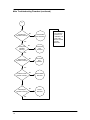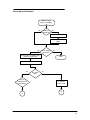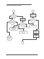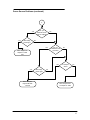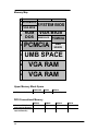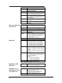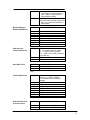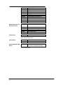
1
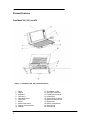
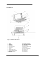
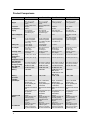
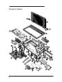
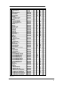
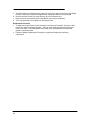
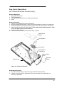
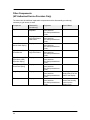
Service Manual HP OmniBook 300, 425, 430, 530 Notice In a continuing effort to improve the quality of our products, technical and environmental information in this document is subject to change without notice. Hewlett-Packard makes no warranty of any kind with regard to this material, including, but not limited to, the implied warranties of merchantability and fitness for a particular purpose. HewlettPackard shall not be liable for errors contained herein or for incidental or consequential damages in connection with the furnishing, performance, or use of this material. Hewlett-Packard assumes no responsibility for the use or reliability of its software on equipment that is not furnished by Hewlett-Packard. As an ENERGY STAR partner, HP has determined that these products meet the ENERGY STAR guidelines for energy efficiency. All Certifications may not be completed at product introduction. Please check with your HP reseller for certification status. This equipment is subject to FCC rules. It will comply with the appropriate FCC rules before final delivery to the buyer. ENERGY STAR is a service mark of the U.S. Environmental Protection Agency. IBM and OS/2 are registered trademarks of International Business Machines Corporation. Pentium and the Intel Inside logo are registered trademarks of Intel Corporation. LapLink Remote Access is a trademark of Traveling Software, Inc. Microsoft, MS-DOS, and Windows are registered trademarks, and the Genuine Microsoft Products logo is a trademark of Microsoft Corporation in the United States of America and in other countries. Hewlett-Packard Company 1996. All Rights Reserved. Reproduction, adaptation, or translation without prior written permission is prohibited except as allowed under copyright laws. Printed in U.S.A. 5965-0244 Table of Contents Table of Figures .........................................................................................................................iv Introduction .................................................................................................................................v Product Overview........................................................................................................................1 Product Features .....................................................................................................................2 OmniBook 300, 425, and 430 ...............................................................................................2 OmniBook 530 .....................................................................................................................3 Product Comparisons...............................................................................................................4 Product at a Glance .................................................................................................................6 Troubleshooting...........................................................................................................................9 OmniBook Self-Test...............................................................................................................10 Loop Back Connectors........................................................................................................10 Troubleshooting Flowchart .....................................................................................................12 Main Troubleshooting Flowchart .........................................................................................13 Power Source Problems .....................................................................................................15 Boot-Up Problems ..............................................................................................................18 Display Problems ...............................................................................................................19 Hard Disk Problems............................................................................................................20 Memory Problems ..............................................................................................................23 Power Management Problems............................................................................................25 Pop-Out Mouse Problems...................................................................................................28 Floppy Drive Problems .......................................................................................................32 Parallel Port Problems........................................................................................................35 Serial Port Problems ..........................................................................................................37 PCMCIA Problems .............................................................................................................39 IR Port Problems ................................................................................................................43 Hardware Repair .......................................................................................................................45 Battery (End User Replaceable).............................................................................................46 Memory (End User Replaceable) ...........................................................................................48 Hard Disk Drive/Flash Card and System ROM (End User Replaceable).................................50 Mouse (End User Replaceable)..............................................................................................52 Small Parts (End User Replaceable) ......................................................................................53 Battery Door .......................................................................................................................53 Battery Door Latch..............................................................................................................53 Blank Modem Door.............................................................................................................53 Memory Door .....................................................................................................................53 I/O Door .............................................................................................................................53 Rubber Feet .......................................................................................................................53 PCMCIA Card Tray.............................................................................................................53 Display (HP Authorized Service Providers Only)....................................................................54 Keyboard (HP Authorized Service Providers Only) ................................................................62 Logic PCA Board (HP Authorized Service Providers Only).....................................................63 Paw Carrier (Paw Active) (HP Authorized Service Providers Only) ........................................65 Other Components (HP Authorized Service Providers Only)..................................................66 Appendix A - Technical and Resource Specifications ................................................................67 Mass Storage Specifications ..................................................................................................67 Card Services and Socket Services Version Matrix................................................................67 Memory Map..........................................................................................................................68 Upper Memory Block Space...................................................................................................68 DOS Conventional Memory ...................................................................................................68 Appendix B - Power On Self Test Codes ...................................................................................69 Beep Codes ...........................................................................................................................69 Display Codes........................................................................................................................70 Appendix C - Password Policy...................................................................................................75 ii Appendix D - Part Numbers.......................................................................................................77 iii Table of Figures Figure 1 - OmniBook 300, 425, and 430 Features .......................................................................2 Figure 2 - OmniBook 530 Features..............................................................................................3 Figure 3 - Serial Loop Back Connector ......................................................................................11 Figure 4 - Parallel Loop Back Connector ...................................................................................11 Figure 5 - OmniBook Memory Modules .....................................................................................48 Figure 6 - Removing the Memory Module..................................................................................49 Figure 7 - Removing Card Slot Tray ..........................................................................................51 Figure 8 - Removing the Mouse ................................................................................................52 Figure 9 - Outer Bottom Case Components ...............................................................................54 Figure 10 - Backplane Standoffs................................................................................................55 Figure 11 - Bottom Case Tabs...................................................................................................55 Figure 12 - Bottom Case Prying Locations.................................................................................56 Figure 13 - I/O Port Prying Location ..........................................................................................56 Figure 14 - Disconnecting Display Cable ...................................................................................57 Figure 15 - Keyboard Flex Cables .............................................................................................58 Figure 16 - Display Grounding Eyelets.......................................................................................58 Figure 17 - Display Cable Probe Position ..................................................................................60 Figure 18 - Reconnecting Display Cable....................................................................................60 Figure 19 - I/O Port Eyelets (all present)....................................................................................61 Figure 20 - I/O Port Eyelets (two matched sets).........................................................................61 Figure 21 - I/O Port Eyelets (only one matched set)...................................................................61 Figure 22 - I/O Port Eyelets (no eyelet in position one) ..............................................................61 Figure 23 - Logic Board PCA Removal......................................................................................63 Figure 24 - Paw Carrier Removal ..............................................................................................65 iv Introduction This document provides reference information for the HP OmniBook 300, HP OmniBook 425, HP OmniBook 430, and HP OmniBook 530. It is intended to be used by HP-qualified service personnel to help with the installation, servicing, and repair of these HP OmniBook PCs. It is a self-paced guide designed to train you to install, configure, and repair the OmniBook Notebook PC. You can follow it without having any equipment available. The following table lists additional sources where supplementary information can be obtained: v Resource HP External Web HP-MCD Internal Web Number/Address http://hpcc998.external.hp.com/mcd/ http://webmcd.cv.hp.com HP MCD Service Engineer [email protected] Comments No usage restriction Restricted to HP internet access only Email address for service related questions and issues Part 1 Product Overview • Product Features • Product Comparisons • Product at a Glance Product Features OmniBook 300, 425, and 430 Figure 1 - OmniBook 300, 425, and 430 Features 1. 2. 3. 4. 5. 6. 7. 8. 9. 10. 2 Latch Display Keyboard Card slot A Card-eject levers On/Off key Mouse Mouse-eject button Display contrast buttons Speaker 11. 12. 13. 14. 15. 16. 17. 18. 19. 20. AC adapter socket Serial port connector Parallel port connector Infrared port System slots (C and D) Memory-expansion slot Modem port Battery compartment Security ring Reset button OmniBook 530 Figure 2 - OmniBook 530 Features 1. 2. 3. 4. 5. 6. 7. 8. 9. 10. 11. Latch Display Keyboard Card slots Card-eject levers On/Off key Mouse Mouse-eject button Display contrast buttons Speaker AC adapter socket 12. 13. 14. 15. 16. 17. 18. 19. 20. 21. Serial port connector Parallel port connector VGA output connector System slots Memory-expansion slot Modem port Battery compartment Security ring Infrared port Reset button 3 Product Comparisons Size Closed Weight Processor Clock Speed Display VGA-out Support Battery OmniBook 300 OmniBook 425 OmniBook 430 OmniBook 530 16.3 x 28.2 x 3.6 cm (6.4 x 11.1 x 1.4 in) 1.31 kg (2.888 lb) w/flash 1.36 kg (2.998) w/hdd 386SXLV 20 MHz 640 x 480 VGA 9-inch diagonal LCD 16 shades of gray none 16.3 x 28.2 x 3.6 cm (6.4 x 11.1 x 1.4 in) 1.31 kg (2.888 lb) w/flash 1.36 kg (2.998) w/hdd 486SLC/e 25 MHz 640 x 480 VGA 9-inch diagonal LCD 16 shades of gray none 16.3 x 28.2 x 3.6 cm (6.4 x 11.1 x 1.4 in) 1.36 kg (2.998 lb) 16.3 x 28.2 x 3.6 cm (6.4 x 11.1 x 1.4 in) 1.36 kg (2.998 lb) 486SLC/e 25 MHz 640 x 480 VGA 9-inch diagonal LCD Intel 486SX 33 MHz 640 x 480 VGA 9-inch diagonal LCD none 4.8 Vdc nickel-metalhydride rechargeable 1.5 V alkaline AA (flash version only) 5 hours w/hdd 9 hours w/flash 100 to 240 Vac (50 to 60 Hz) input 12 Vdc output less than 1.5 hours w/ac adapter 0 to 40 C (32 to 104 F) 4.8 Vdc nickel-metalhydride rechargeable 1.5 V alkaline AA (flash version only) 4.5 hours w/hdd 8 hours w/flash 100 to 240 Vac (50 to 60 Hz) input 12 Vdc output less than 1.5 hours w/ac adapter 0 to 40 C (32 to 104 F) 4.8 Vdc nickel-metalhydride rechargeable 1.5 V lithium AA 640 x 480, 16 or 256 colors 800 x 600, 16 colors 4.8 Vdc nickel-metalhydride rechargeable 0 to 55 C (32 to 131 F) © 4.5 hours 4 hours 100 to 240 Vac (50 to 60 Hz) input 12 Vdc output less than 1.5 hours w/ac adapter 0 to 40 C (32 to 104 F) 100 to 240 Vac (50 to 60 Hz) input 12 Vdc output less than 1.5 hours w/ac adapter 0 to 40 C (32 to 104 F) 0 to 55 C (32 to 131 F) 0 to 55 C (32 to 131 F) 0 to 55 C (32 to 131 F) 90% relative humidity at 40 C (104 F) maximum 90% relative humidity at 40 C (104 F) maximum 90% relative humidity at 40 C (104 F) maximum 90% relative humidity at 40 C (104 F) maximum 40-MB hard disk 10-MB flash disk 2 MB RAM 40-MB hard disk 10-MB flash disk 2 MB RAM 130-MB hard disk Memory Expansion Available Input/Output 2-MB, 4-MB 2-MB, 4-MB 105-MB hard disk 40-MB hard disk 2 MB RAM on 40MB version 4 MB RAM on 105MB version 2-MB, 4-MB 9-pin, 115K baud, RS-232 port 25-pin parallel port 115K baud, bidirectional infrared port Communication port for optional fax/modem 9-pin, 115K baud, RS-232 port 25-pin parallel port 115K baud, bidirectional infrared port Communication port for optional fax/modem 9-pin, 115K baud, RS-232 port 25-pin parallel port 115K baud, bidirectional infrared port Communication port for optional fax/modem 9-pin, 115K baud, RS-232 port 25-pin parallel port 115K baud, bidirectional infrared port Communication port for optional fax/modem Keyboard and Mouse 85 keys Industry-standard, fullsized key spacing Embedded numeric keypad 9 Fn keys Built-in pop-up mouse PCMCIA, Type II, Version 2.0 card slots Two slots available with 85 keys Industry-standard, fullsized key spacing Embedded numeric keypad 12 Fn keys Built-in pop-up mouse PCMCIA, Type II, Version 2.0 card slots Two slots available with 85 keys Industry-standard, fullsized key spacing Embedded numeric keypad 12 Fn keys Built-in pop-up mouse PCMCIA, Type II, Version 2.0 card slots One slot available with 85 keys Industry-standard, fullsized key spacing Embedded numeric keypad 12 Fn keys Built-in pop-up mouse Two PCMCIA Type II slots (one Type III slot) Optional floppy disk Battery Life AC Adapter Recharge Time Operating Temperature Storage Temperature (with data retention) Operating and Storage Humidity Mass Storage Available Memory Expandability 4 4 MB RAM 4-MB, 8-MB Pre-installed Software OmniBook 300 OmniBook 425 OmniBook 430 OmniBook 530 the flash disk version One slot available with the hard disk version © MS Windows 3.1* © MS DOS 5.0* MS Word 2.0* MS Excel 4.0* LapLink Remote ™ Access Phone Book Appointment Book HP Financial Calculator the flash disk version One slot available with the hard disk version © MS Windows 3.1* © MS DOS 5.0* MS Word 2.0* MS Excel 4.0* LapLink Remote ™ Access Phone Book Appointment Book HP Financial Calculator the hard disk version drive © MS Windows 3.1 © MS DOS 6.2 LapLink Remote ™ Access Phone Book Appointment Book HP Financial Calculator © MS Windows 3.11 © MS DOS 6.2 LapLink Remote ™ Access Phone Book Appointment Book HP Financial Calculator *(Note: All components not included can be installed from a retail copy. License for full Microsoft Word, Microsoft Excel, MSDOS, and Microsoft Windows is included with purchase.) 5 Product at a Glance 14 28 14 29 27 17 32 35 11 13 16 33 16 5 10 6 2 1 9 18 2 1 1 1 2 2 15 13 7 2 2 13 24 2 12 2 2 26 5 2 30 2 23 13 4 3 6 19 20 8 2 31 21 22 34 25 6 10 Description Part Number OB300 OB425 OB430 OB530 Standoff 0380-4060 Screw M2x4.6mm (T6) 0515-2396 Mouse 5061-4390 Arm Eject Mouse Spring F1030-00016 Pivot Door Spring F1030-00026 Spring Card Eject F1030-00029 Mouse Latch Spring F1030-00030 Mylar Mouse Shield F1030-20001 Door Battery Door Battery (10 pack) F1030-60912 Door Battery (silver) F1052-40012 10 Pivot Door Pivot Door (PCMCIA) A F1030-40013 Pivot Door (PCMCIA) B F1030-40014 Pivot Door (PCMCIA) Left F1052-40007 11 Door Modem Blank F1030-40016 12 Door RAM F1030-40017 13 Rubber Foot F1030-40018 14 Hinge Cap F1030-40019 15 Mouse Button Latch F1030-40021 16 Battery Door Latch F1030-40025 17 Security Latch F1030-40033 18 Eject Button A F1030-40044 19 Eject Button B F1030-40045 20 Eject Arm Left F1030-40046 21 Eject Arm Right F1030-40047 22 Paw Carrier Srvc Assy F1030-60901 23 Arm Eject Mouse F1030-40050 24 Door I/O F1030-60908 25 Pivot Bracket F1030-60909 26 Bottom Case Bottom Case F1030-60910 Bottom Case (silver) F1052-60908 27 Top Case Top Case F1030-60911 Top Case (silver) F1052-60907 28 LCD Display Assy (new) F1030-60904 29 Keyboard Keyboard USA F1030-80013 Keyboard German F1030-80031 Keyboard Spanish F1030-80032 Keyboard French F1030-80033 Keyboard International English F1030-80057 30 Logic PCA Logic PCA (new) F1030-60907 Logic PCA (new) F1033-60907 Logic PCA (new) F1052-60906 Logic PCA (exchange) F1052-69008 31 System ROM System ROM (ABA) - US English F1033-60908 System ROM (ABB) Int. English F1033-60909 System ROM (ABD) German F1033-60910 System ROM (ABF) French F1033-60911 System ROM (ABE Spanish) F1033-60912 System ROM (ABA) US English F1037-60903 System ROM (ABB) Int. English F1037-60904 System ROM (ABD) German F1037-60905 System ROM (ABE) Spanish F1037-60906 System ROM (ABF) French F1037-60907 32 Battery Pack F1045-60901 33 Hard Drive Tray F1065-60029 34 Flash Tray F1030-60923 35 Mass Storage 5 MB Flash Disk Card F1012-60902 10 MB Flash Disk Card F1013-60901 20 MB Flash Disk Card F1014-60901 40 MB Hard Drive (DOS/Win/PIM) F1035-60901 40 MB Hard Drive (unprogrammed) F1050-60901 105 MB Hard Drive (DOS/Win/PIM) F1037-60908 105 MB Hard Drive (Word/Excel) F1037-60909 105 MB Hard Drive (unprogrammed) F1039-60901 130 MB Hard Drive (unprogrammed) F1057-60901 130 MB Hard Drive (programmed) F1052-60909 Note, this is a partial parts list. For a complete parts list, please refer to Appendix D or the current Product Support Plan. 1 2 3 4 5 6 7 8 9 7 Part 2 Troubleshooting • OmniBook Self Test • Troubleshooting Flowchart OmniBook Self-Test The OmniBook Self-Test provides on-board hardware and firmware diagnostics. To operate the self-test, perform the following steps: 1. 2. 3. 4. 5. Save all files and close all applications: The OmniBook is reset at the end of the self-test. Turn the OmniBook OFF. Press and hold the [Esc] key and press [ON]. You will hear a short three-tone beep. Self Test will initialize and start. To run a test: Highlight the test name and press [ENTER]. Highlight the test name and press [Ctrl][ENTER] to run a longer and more extensive version of a test--not available for all tests. The test runs and its results are reported. 6. To run several tests in a continuous loop: Highlight one or more using [ space bar ] and press [ENTER]. Each test runs and its results are reported. Press [Backspace] to stop the loop. 7. To exit the self-test, press [Esc]. Interpretation of test results A result of “OK” on any test indicates that the test did not find problems while the unit was operating in its current state. A “BAD” result indicates that the test found a problem while the unit was operating in its current state. A “BAD” result should always be confirmed by running the test in a loop for several iterations or running the long version of the test. Further inspection of the unit to rule out configuration or installation conflicts is necessary prior to diagnosing the unit as needing repair. Any test that is halted by [Backspace] is shown as “aborted” and no results are displayed. The OmniBook will not enter sleep mode while the self-test is executing. Loop Back Connectors In order to run the RS232 serial port or parallel port self-test, a loop back connector is needed. The loop back may be placed on either the OmniBook port or at the end of the corresponding cable. This feature is also helpful in diagnosing a defective serial or parallel cable. Loop back connectors may be purchased or can easily be constructed. The following illustrations identify the correct pin-out configurations for the serial and parallel loop back connectors. 10 Figure 3 - Serial Loop Back Connector Figure 4 - Parallel Loop Back Connector 11 Troubleshooting Flowchart The following series of flowcharts is intended as a guide for troubleshooting the OmniBook 300, 425, 430, and 530. Each technician should still rely on personal experience and supplemental knowledge when diagnosing a problem. These tips should be kept in mind when referencing the troubleshooting flowcharts: • • • 12 Use the Main Troubleshooting Flowchart to isolate the problem to a particular area. Use the additional individual troubleshooting flowcharts to narrow down the problem to a specific component or item. Always use supplemental information resources, including the Product Support Plan, Service Notes, and the World Wide Web, to aid in diagnosing problem areas. Main Troubleshooting Flowchart START No See Hard Disk flowchart No See Memory flowchart See DOS or Windows? Get user information: Name Telephone number Unit serial number Repair history Yes Memory OK? (No memory errors) Yes Eliminate all obvious physical problems? No Isolate damage. Refer to repair process Yes No Hard disk operates OK? Yes No OB unit's power light comes on? Unit has at least 11/2 hours battery life? No Single beep during boot-up? See Bootup flowchart No See Power Management flowchart Yes Pop-out mouse works correctly? Yes See something in display? Yes See Power Source flowchart Yes See Hard Disk flowchart No See Mouse flowchart No See Display flowchart Yes External floppy drive operates correctly? No See Floppy Drive flowchart Yes A 13 Main Troubleshooting Flowchart (continued) A Parallel port operates correctly? No See Parallel Port flowchart Yes Serial port operates correctly? No See Serial Port flowchart Yes External VGA operates correctly? No See Serial Port flowchart Yes PCMCIA cards operate correctly? Infrared port operates correctly? Yes 14 No See PCMCIA flowchart No See IR flowchart If you still have a problem, it's in software or in a part of the unit not covered by these flowcharts. Power Source Problems Start: No power lamp, or low battery life Yes Battery in Omnibook? No Turn Omnibook off Remove and reinsert battery Yes HP ac adapter and cable? Connect OB to ac adapter, plug adapter into wall socket No Done Turn on Omnibook Yes Light on continuously (not intermittent)? See power light? No Try different power socket B A 15 Power Source Problems (continued) A Yes B Light on continuously (not intermittent)? Try different power socket No Recheck cables, connections: ac adapter to Yes Ambient temperature within specification? Yes No No Yes Light still intermittent? No Done: Power source problem Done Done: Bring temperature within specifications Done: Suspect bad ac adapter, cable, or connector Ensure power coming from wall socket Ensure battery installed correctly Go to Power Management Problems flowchart C 16 See power light? Power Source Problems (continued) C Can you substitute known good ac adapter? Yes Yes See steady power light? No No Yes Done: Original ac adapter or cable bad Can you substitute known good OB? Yes Yes Done: Suspect original OB base unit bad See steady power light? No Ac adapter warm? No No Done: Suspect bad ac adapter or cable 17 Boot-Up Problems Start: Problems during bootup Press Ctrl Alt Del to get a clean boot Multiple beeps Hear single or multiple beeps during boot? Single beeps Yes See Windows or DOS prompt in display? Done Yes Yes OB support utility disk available? No No OB support utility disk available? No Suspect software problem: locate OB support utility disk and call back Insert OB support utility disk and reboot Yes Done 18 See prompt to enter time and date? No Done: Suspect bad Omnibook base unit Display Problems Start: Power light on, but no display Physical inspection of display Adjust brightness and contrast controls Yes Done See anything in display? No Go to Boot-Up Problems flowchart 19 Hard Disk Problems Start: Hard disk fails to boot up to DOS or Windows; or other hard disk problems See anything in drive C:? Yes Yes Yes Noisy? No HP hard disk? No No Insert hard disk in C: Done Speech: Need hard disk to boot correctly Yes See "Nonsystem disk"? No Done: Hard disk bad Done Suspect corrupt files on hard disk Insert hard disk containing system files Boot from OB companion disk in drive A: Done Do SCANDISK C: Yes A 20 Soft checking OK? No B Hard Disk Problems (continued) A B Do hard checking. Save logs. Let SCANDISK repair errors. Do hard checking. Save logs. Let SCANDISK repair errors. Yes Boot from OB companion disk in drive A: No Space available on hard disk within spec? Do SCANDISK C: Done: Hard disk bad Boot from drive C: Yes Boots without errors? Do CHKDSK C: No Yes No Number of bad sectors out of spec? Suspect software problem Done: Hard disk bad Done Go to Boot-Up Problems flowchart Boot from OB companion disk in drive A: Do SCANDISK C: /AUTOFIX C 21 Hard Disk Problems (continued) C Remove disk from drive A: Boot from drive C: Yes DOS and Windows boot OK? No Give customer general data recovery hints Done Yes Is customer willing to reformat hard disk? No Boot from drive A: Done: Customer must purchase another hard disk Back up hard disk to A: Reformat hard disk Reload image Done 22 Memory Problems Start: Problem with plug-in memory Yes No Intermittent problem? End current session. Run short OB memory self-test Yes Memory self-test OK? Exit software and turn off OB No Remove OB battery, disconnect ac adapter Run long OB memory self-test Yes Memory self-test OK? Run different software to eliminate potential software Yes Remove and examine memory module No Done: Suspect bad memory module Yes Memory appears OK now? Done: Suspect memory module problem Module appropriate and compatible? No With memory module removed, replace battery, attach ac adapter No Done A Done: Memory inappropriate for this model OB 23 Memory Problems (continued) A Power up OB (memory module removed) Yes Memory problem disappears? No Run short OB memory self-test (without memory module) Done: Suspect bad memory module Yes Memory self-test OK? No Run long OB memory self-test (without memory module) Yes Done: Suspect memory module bad 24 Memory self-test OK? No Done: Suspect OB base unit bad Power Management Problems Start: Low battery life Yes Physical inspection: HP battery? Contacts dirty? Physically OK? Done: Suspect software problem Yes Yes Ac adapter attached to OB and wall? No See OB power icon? No Is Windows running? No Start Windows Attach ac adapter Yes Yes Has unit recharged sufficiently? OB Power icon in Control Panel? No Yes Power Mgmnt icon in OB Tools? Recharge sufficiently Yes Yes Power on during recharge? No 1-1/2 hours per charge? No No Speech: Standard or Off means processor always on; uses more power No Ensure power on Done Yes DOS or Windows running? Enable OB power management No Start DOS or Windows A Done 25 Power Management Problems (continued) A Yes Yes Ambient temperature in spec? "Bad/no battery" message? Yes Ensure ac adapter plugged into OB and wall No Charging circuitry may be defective No Yes "Bad/no battery" message? Done: Replace battery or use OB on ac power only PCMCIA cards installed? No Yes Speech: PCMCIA cards can use power even when not on No Speech: DOS games, TSR's, other software can reduce battery life Remove PCMCIA cards, recharge battery Yes Get 1-1/2 hours battery life? 3rd-party software installed? Disable 3rd-party software and recharge battery No Done B 26 No Bring ambient temperature within specification, recharge battery Clean boot: Ctrl Alt Del, press F4 during boot Yes Does battery indicator reach full charge? No Power Management Problems (continued) B Yes No Get 1-1/2 hours battery life? Use MSD to determine what TSR's are running Done Disable TSR's Yes Done Get 1-1/2 hours battery life? No Done: Suspect bad or old battery 27 Pop-Out Mouse Problems Start: OB popout mouse problem Eliminate obvious physical problems Yes See Windows? No Start Windows running Yes Is mouse OB popout mouse? No Disable other mouse Enable OB popout mouse Yes Yes A 28 See mouse pointer? No Done: Suspect software problem (Windows problem) Does mouse pointer move? B Pop-Out Mouse Problems (continued) A Yes Reaches all 4 corners of screen? Yes Yes Is mouse jittery, intermittent? No Can you calibrate mouse? No No Done: Mouse should be OK Suspect bad mouse C 29 Pop-Out Mouse Problems (continued) B Suspect software configuration problem Yes Setup shows correct mouse driver? No Check for correct OB mouse driver Configure Setup for correct OB mouse driver Yes Mouse driver OK? No Look at mouse in Windows Control Panel Yes Mouse moves? No Done: Replace with known good version of correct OB mouse driver Yes See OB punch button? Done: Mouse OK No Set Control Panel for OB punch button mouse Suspect bad mouse Yes OB mouse works OK? No Done Exit Windows, run Setup from DOS command line 30 C Pop-Out Mouse Problems (continued) C Run OB diagnostic program Yes Yes OB mouse operates correctly? No Suspect mouse works in known good OB? Yes Does mouse pass all tests? Boot normally to Windows Can you put suspect mouse in known good OB? Yes Clean boot: Ctrl Alt Del, press F5 when starting No Put known good OB mouse in suspect base unit No Remove mouse from OB base unit, examine mouse, and reinsert Yes Known good mouse works? No No Suspect bad mouse. Run OB diagnostic program Done: Suspect software problem Yes Does mouse pass all tests? No Replace mouse. Have customer call back if problem not solved. Done Done: Suspect bad OB base unit Done 31 Floppy Drive Problems Start: External floppy disk drive problem External FDD is HP device? Yes Yes Cable is correct one? No No Done Locate and attach correct cable Eliminate obvious physical problems: Cable OK? Pins not bent? Cable connected and solidly in connectors? Yes Drive works OK? Done Yes Yes A 32 Has drive ever worked? Inserts, ejects known good disk cleanly? No No B Done: Suspect bad or damaged drive No Floppy Drive Problems (continued) A Clean boot: Ctrl Alt Del, press F5 during boot Yes Drive works OK? No Done Run short selftest twice Yes With original OB turned on, connect good drive and cable Can you swap with known good drive and cable? No Yes Suspect software problem (proceed to B) Yes Good drive works OK? Original drive works OK? Suspect software problem No Done: Suspect bad drive No With known good OB turned on, connect original drive and cable Yes Drive passes self-test OK? With known good OB turned on, connect original drive and cable No Yes Original drive or cable bad Original OB base unit bad Original drive works OK? No Suspect software problem 33 Floppy Drive Problems (continued) B Clean boot: Ctrl Alt Del, press F5 during boot Yes Run OB disk self-test: Put empty, known good disk, formatted for DOS, in drive. Press Enter. No Boot from drive A: with OB companion disk Yes Boots OK? Insert blank, formatted floppy disk, do long-term disk self-test Repeat disk self-test Yes Done: If long-term self-test works but floppy drive still has problem, suspect runtime environment software problem 34 Disk self-test OK? Long-term self-test OK? Change diskette, run self-test again No Yes No Self-test OK? Suspect bad floppy diskette; replace floppy with known good one Done: Suspect bad floppy drive No Parallel Port Problems Start: Problem with parallel port Use PRN command to print a file Yes No Problem with Laplink Remote? Yes Prints file OK? No Other printer available? No Troubleshoot Laplink Remote Done: Parallel port OK Yes Physical inspection: Cable connected? Cable pins OK? Attach OB and use PRN command to print file on different printer Clean boot: Ctrl Alt Del, press F5 during boot Yes Exit to DOS See Windows? Yes No Done: Suspect bad printer or cable Prints file OK? No Run OB self-test diagnostics: CDIAG or OBTEST, depending on unit A 35 Parallel Port Problems (continued) A Yes Self-test OK? Reconfirm: Printer plugged in? On? On line? Done: Bad OB base unit Attach printer to desktop PC Clean boot to DOS on desktop PC: Ctrl Alt Del, press F5 during boot Yes Done: Suspect original OB bad 36 PRN prints file OK? No No Done: Suspect bad printer or cable Serial Port Problems Start: Problem with serial port Yes Problem with Laplink Remote? No Troubleshoot Laplink Remote Install loopback connector Physical inspection: Cable connected? Bent pins? Cable appears OK? Run OB self-test procedure Yes Self-test OK? Connected to what? Modem? Printer? Other? No Done: Serial port OK Yes Done: Suspect bad serial port in OB base unit Loopback connector available? No A 37 Serial Port Problems (continued) A Ensure proper default serial port configuration Yes No Serial port works OK? Done Yes Can you eliminate all potential software conflicts? No Eliminate software conflicts Yes No Serial port works OK? Done Yes Done: Suspect original device or cable bad 38 Plug another device and cable into serial ports Serial port works OK? No Done: Suspect bad OB base unit serial port PCMCIA Problems Start: PCMCIA card problem Determine type of card Yes Known issue with this card? No Seek additional information on card Yes Yes Has card ever worked? Has any software been loaded or modified since card worked? No No Remove card (with power on or off) Visually inspect card: Connectors bent? Damaged? Wet? Suspect software configuration problem Yes Inspection reveals problems? No Reinsert card Done: Suspect bad PCMCIA card B A 39 PCMCIA Problems (continued) A B Clean boot: Ctrl Alt Del, press F5 during boot Press Ctrl Alt Del Run OB self-test Yes Yes Self-test OK? See Windows display? No Exit to DOS prompt Yes See DOS prompt? Suspect bad card Done: Return card to HP HP card? No Done: Contact card vendor Remove card and run CARDINFO Interpret CARDINFO results C 40 No Exit to DOS prompt Done: Software configuration or setup problem Yes No PCMCIA Problems (continued) C Yes No Hardware problem? Done: Suspect bad OB base unit Yes Check CONFIG.SYS and AUTOEXEC.BAT Software problem? No Insert card in top slot Run CARDINFO Done Insert same card in bottom slot Yes Hardware problem in both slots? No Suspect bad card Yes Card is HP device? Run CARDINFO No Interpret results Done: Contact card vendor Done: Replace card D 41 PCMCIA Problems (continued) D Yes Hardware problem in one slot only? Done: Suspect bad OB base unit No Yes Software problem in both slots? Yes Seek further information consult with Technical Support 42 Done: Suspect software configuration problem No Software problem in one slot only? No Done IR Port Problems Start: Problem with infrared (IR) port Yes Problem with Laplink Remote? Clean boot: Ctrl Alt Del, press F5 during boot No Troubleshoot Laplink Remote Run OB self-test Physical inspection: IR port not covered? Painted over? Obscured? Run IR self-test in proper environment Yes Ensure operating distance within specification (1 meter or less) IR self-test OK? Done: Suspect software problem No Move OB to different desk, room Run IR self-test in proper environment Ensure operating environment OK: Not next to bright or oscillating light? Yes Done: Suspect no problem or software problem IR self-test OK? No Done: Suspect bad OB base unit 43 Part 3 Hardware Repair • Battery • Memory • Hard Disk Drive/Flash Card and System ROM • Mouse • Small Parts • Display • Keyboard • Logic PCA Board • Paw Carrier • Other Components CAUTION: Always provide proper grounding when performing any of the following repairs. An electrostatic discharge may cause irreparable damage to the OmniBook and its components Battery (End User Replaceable) All of the monochrome OmniBook models use the same HP Nickel-Metal-Hydride (NiMH) Battery Pack, part number F1045A (service replacement part number F1045-60901). However, for some models, 1.5 V AA batteries can be used in place of the NiMH battery pack. The following table lists all of the monochrome OmniBooks and the batteries that can be used safely in each model. Flash Disk Version Hard Disk Version WARNING: OmniBook 300 • NiMH Battery Pack • AA Alkaline • AA Lithium • NiMH Battery Pack • AA Lithium OmniBook 425 • NiMH Battery Pack • AA Alkaline • AA Lithium • NiMH Battery Pack • AA Lithium OmniBook 430 not applicable OmniBook 530 not applicable • NiMH Battery Pack • AA Lithium • NiMH Battery Pack Do not mutilate, puncture, or dispose of batteries in fire. The batteries can burst or explode, releasing hazardous chemicals. A nickel-metal-hydride rechargeable battery pack must be recycled or disposed of properly. Recycle or discard used size-AA batteries according to the manufacturer’s instructions. Required Equipment • none Removal Procedure 1. Release the two latches on the battery cover on the bottom case, then remove the cover. Refer to the below illustration. 2. Do one of the following to remove the battery: • If an OmniBook battery pack is installed, lift it out by its tab. • If AA batteries are installed in place of the OmniBook battery pack, lift each out individually. 46 Replacement Procedure 1. To replace the battery, do one of the following: • To replace the OmniBook battery pack, insert the rounded side of the pack into the compartment first. It is not possible to fully insert the battery pack incorrectly. • To replace AA batteries, orient them as shown by the symbols in the battery compartment. 2. Replace and latch the battery cover. 47 Memory (End User Replaceable) The OmniBook 530 uses a unique memory module that is not compatible with the OmniBook 300, 425, or 430. The table below summarizes the compatibility of the memory modules for each OmniBook model. Memory Module 2-MB 4-MB 4-MB 8-MB Accessory Number F1041A F1042A F1054A F1055B Service Replacement OB 300 OB 425 OB 430 OB 530 F1041-60901 F1038-60901 F1054-60901 F1055-60002 The following illustration provides a visual representation of the physical differences between the memory module for the OmniBook 300, 425, and 430 and the memory module for the OmniBook 530. OmniBook 300, 425, and 430 OmniBook 530 Figure 5 - OmniBook Memory Modules 48 Required Equipment • Probe (or similar device) for the OmniBook 300, 425, and 430 only CAUTION: To avoid damage due to electrostatic discharge, handle the memory module by the edges only. Removal Procedure 1. Remove the battery and ac adapter from the OmniBook. 2. Slide the memory door off (see below illustration). Figure 6 - Removing the Memory Module 3. Perform the appropriate action for the corresponding OmniBook: • OmniBook 300, 425, or 430 -- Use a probe or similar device to pull on the small post located on the front edge of the memory module. • OmniBook 530 -- Flip out the plastic tab on the memory module and pull the module out. Replacement Procedure 1. Insert the memory module into the slot. (It is not possible to completely insert the memory if it is upside down.) • OmniBook 300, 425, 430 -- the small post on the board faces the bottom surface of the OmniBook. • OmniBook 530 – the plastic tab on the board faces the bottom surface of the OmniBook. 2. Press in the module until it seats fully. 3. Replace the slot cover. 4. Replace the battery and press reset. 49 Hard Disk Drive/Flash Card and System ROM (End User Replaceable) The Hard Disk Drives for the OmniBook 300, 425, 430, and 530 can be reimaged if necessary. If the software is corrupted, or otherwise damaged, on the hard drive, it can be reformatted and the software reloaded. Also, if the hard drive fails and must be replaced, a blank hard drive can be ordered and the appropriate software loaded. The below procedures indicate the proper actions necessary for reloading software on each OmniBook model. For the OmniBook 300 and 425: 1. Place the hard drive into the OmniBook. 2. Reformat the hard drive. 3. Run OBSETUP /F from the System ROM to reload the software onto the hard drive. For the OmniBook 430: 1. Place the hard drive into the OmniBook. 2. Reboot and press Alt then D to boot from the System ROM. 3. Reformat the hard drive. 4. Reload the software image from a set of OmniBook 430 Recovery Disks. The Recovery Disks are available on the HP Internal WW Web at http://webmcd.cv.hp.com/prodsupp/archive/. For the OmniBook 530: 1. Place the hard drive into the OmniBook. 2. Boot from the Companion Disk or other bootable floppy disk. 3. Reformat the hard drive. 4. Reload the software image from a set of OmniBook 530 Recovery Disks. The Recovery Disks are available on the HP Internal WW Web at http://webmcd.cv.hp.com/prodsupp/archive/. 50 Required Equipment • none Removal Procedure 1. Exit all applications, including Windows. 2. Turn the OmniBook off and remove the battery and ac adapter. 3. Turn the OmniBook over, release the two latches on the bottom of the tray, and pull out the tray. See below illustration. Figure 7 - Removing Card Slot Tray 4. Lift the Hard Disk, Flash Card, or System ROM out of the tray. Replacement Procedure 1. Reverse the above steps to replace the Hard Disk, Flash Card, or System ROM. 2. Replace the battery and ac adapter. 3. Press reset. 51 Mouse (End User Replaceable) Required Equipment • none Removal Procedure 1. Press the mouse-eject button to eject the mouse. 2. Pull the mouse firmly away from the OmniBook (see below illustration). The entire mouse assembly will pull free. Figure 8 - Removing the Mouse Replacement Procedure 1. Place the end of the mouse “stick” into the mouse housing. 2. Slide the mouse into the slot and firmly push the mouse until it is completely flush with the side of the OmniBook. 52 Small Parts (End User Replaceable) The following small parts are all end user replaceable. Battery Door Push the two battery door latches away from the battery door. Remove the battery door by lifting up at the notch in the bottom case. Place the battery door, tab side first, over the battery compartment. Slide the two battery latches in place to secure the door. Battery Door Latch Once the battery door is removed (see above), the battery door latches will slide out of the bottom case. To replace, align the sides of the latches with the groves in the slots. Press firmly into place. Blank Modem Door Use a flat-blade screwdriver or similar device to press the small latch on the bottom of the blank modem door. Pull the door free of the bottom case. To replace, simply reinsert the door into the modem slot and press firmly. Memory Door Use a flat-blade screwdriver or similar device to pry the memory door from the bottom case. Replace by aligning the edges of the door with the slots on the bottom case. Press firmly into place. I/O Door To remove the I/O door, open it fully. Flex the middle of the door until the side pins clear the holes in the back case. Reverse to replace. Rubber Feet Place a probe or similar device between the rubber foot and the plastic of the bottom case. Pry upward to pop the foot out. To replace, firmly press the foot into the hole. PCMCIA Card Tray Slide the two tray latches toward each other. Pull the tray out of the card slot. If present, remove the PCMCIA card from the tray. To replace the tray, insert into the appropriate card slot. Slide the two latches away from each other to secure the tray. 53 Display (HP Authorized Service Providers Only) Required Equipment • Appropriate ESD station • Torx #6 screwdriver • 5mm Hexdriver • Two small flat tip screwdrivers (or similar prying devices) • Probe Removal Procedure 1. Remove the battery, ac adapter, mass storage, system card (if applicable), memory module (if installed), modem (if installed), mouse, and any installed PCMCIA accessory cards. 2. Remove the four Rubber Feet and seven Screws from the bottom case (see below illustration). Door - Battery Screw M2x4.6mm(T6) (Qty 6) Battery Rubber Foot (Qty 4) Figure 9 - Outer Bottom Case Components 54 3. Remove the I/O Door and the four standoffs located on the I/O backplane (see figure below). Figure 10 - Backplane Standoffs 4. Two flat tip screwdrivers, or similar prying devices, are needed to remove the Top Case and Display Assemblies. Four plastic tabs hold the Top Case and Bottom Case together. Two tabs are located in each PCMCIA slot (see below illustration). Note, the screws seen in the PCMCIA slot do not need to be removed. Figure 11 - Bottom Case Tabs 55 Place a prying device at a tab location between the metal and plastic of the Bottom Case (see figure below, left). Place another prying device in the PCMCIA eject button (see figure below, right). To release the tab, simultaneously twist prying device A while lifting on prying device B. Use caution with this maneuver, as the plastic tabs can break off the Bottom Case. If this occurs, the Bottom Case must be replaced. Prying device “A” Prying device “B” Figure 12 - Bottom Case Prying Locations 5. Perform step four for each of the four tabs. 6. Once the Bottom Case tabs are released, the Bottom Case and Top Case are being held together only by the display cable and the two keyboard cables. Do not allow the Top Case and Bottom Case to separate at this point. The display cable and keyboard cables will be damaged if they are not properly disconnected. 7. Use a prying device to increase the separation of the Top Case and Bottom Case (see figure below). Do not separate the Top Case and Bottom Case more than 1 cm. A separation greater than 1 cm will damage the keyboard flex cables by pulling them out of the zero-force insertion connectors. The intent is to be able to view the display cable, located to the left of the ac adapter socket. Display Cable Figure 13 - I/O Port Prying Location 56 8. With the separation increased slightly, the display cable can be disconnected using a probe. Use caution to keep the OmniBook on a level surface. With the Top Case partially separated, small internal parts may dislodge when the OmniBook is tilted at a sharp angle. Place the probe at the base of the display cable connector between the two rows of pins. Use a rocking motion to lift the cable from the connector. See the below illustration for proper placement of the probe. Figure 14 - Disconnecting Display Cable 9. With the display cable removed, the Top Case and Bottom Case can be opened partially to gain access to the keyboard flex cables (see below illustration). Do not open the unit completely as this will damage the keyboard flex cables by pulling them out of the zero-force insertion connectors. Open the zero-force insertion connectors and remove the keyboard flex cables. The Top Case can now be removed completely from the Bottom Case. 57 Figure 15 - Keyboard Flex Cables 10. To separate the Keyboard from the Display, five grounding eyelets must be removed from the display posts (see below illustration). Use caution when removing the grounding eyelets, as they can be broken off easily. If this happens, the assembly must be replaced. To prevent the eyelets from breaking, bend the grounding eyelet tabs at the farthest point from the eyelet. Proper Tab Bend Figure 16 - Display Grounding Eyelets 58 11. To remove the Display from the Top Case, the display cable and two grounding cables must be guided through the holes in the Top Case. Replacement Procedure 1. Guide the display posts, display cable and two grounding cables on the Display through the holes in the Top Case. 2. Replace the grounding eyelets over the display posts (see Figure 16). Use caution when replacing the grounding eyelets, as they can be broken off easily. If this happens, the assembly must be replaced. 3. Press the Display and Top Case firmly at each display post to snap the assembly in place. 4. Position the Top Case and Display Assembly over the Bottom Case and insert the two keyboard flex cables into the zero-force insertion connectors. Ensure the connectors are fully closed. Once the keyboard flex cables are secured in the connectors, do not allow them to be pulled out. This will damage the cables. 59 5. To reconnect the display cable, position a probe in the cable as shown in the below illustration. Figure 17 - Display Cable Probe Position 6. Use the probe to connect the display cable into the connector as shown below. Use caution to keep the OmniBook on a level surface. With the Top Case partially separated, small internal parts may dislodge when the OmniBook is tilted at a sharp angle. Figure 18 - Reconnecting Display Cable 7. With the display cable reconnected, the I/O grounding eyelets must be slid into place. Use caution when positioning the I/O grounding eyelets as they can be broken off easily. It is acceptable to reassemble the OmniBook with certain I/O grounding eyelets broken if there is at least one eyelet in each of the four positions AND at least two matched sets remaining. See Figure 19, Figure 20, Figure 21, and Figure 22 for examples. 60 Acceptable to reassemble All eyelets are present. Figure 19 - I/O Port Eyelets (all present) Acceptable to reassemble There are two matched sets and at least one eyelet in each position. Figure 20 - I/O Port Eyelets (two matched sets) Not acceptable to reassemble There is only one matched set. Figure 21 - I/O Port Eyelets (only one matched set) Not acceptable to reassemble There are two matched set, but no eyelet in position one. Figure 22 - I/O Port Eyelets (no eyelet in position one) 8. Open the display and firmly press the Top Case and Bottom Case together around the entire parameter of the OmniBook. This will lock the tabs of the two cases. 9. Replace the seven screws and four standoffs and the remainder of the components. 61 Keyboard (HP Authorized Service Providers Only) Required Equipment • Appropriate ESD station • Torx #6 screwdriver • Two small flat tip screwdrivers (or similar prying devices) • Probe Removal Procedure 1. Follow the Display Removal Procedure to separate the Display and Top Case from the Bottom Case. 2. Once the Display is removed, the Keyboard must now be separated from the Top Case. Hold the Top Case and Keyboard Assembly exactly as shown in the below illustration. Top Case and Keyboard Assembly (upside down) Keyboard (upside down) Backside of the Top Case icon panel. Figure - Keyboard Removal Hand Placement 3. Apply even upward pressure with the fingers of the left hand. At the same time use the tip of the thumb of the right hand to twist the backside of the Top Case icon panel inward and toward the keyboard. There will be a slight bending in the plastic of the Top Case. This is normal and will not damage the assembly. Replacement Procedure 1. To replace the Keyboard, snap it into the Top Case. Ensure the entire perimeter of the Keyboard is securely snapped into place. 2. Follow the Display Replacement Procedure to replace the Display and remaining components. 62 Logic PCA Board (HP Authorized Service Providers Only) Required Equipment • Appropriate ESD station • Torx #6 screwdriver • Two small flat tip screwdrivers (or similar prying devices) • Probe Removal Procedure 1. Follow the Display Removal Procedure to separate the Display and Top Case Assembly from the Bottom Case. 2. Remove the Eject Arms (both right and left) and Mouse Button Latch and Spring (see below illustration). Note, the Mouse Latch Spring is very small and can be misplaced easily. Screw M2x4.6mm(T6) (Qty 5) Eject Arm Right Mouse Button Latch Eject Arm Left Mouse Latch Spring Logic PCA Paw Carrier Flex Cable Slot Eject Arm Spring Eject Button A Eject Button B Eject Arm Spring Figure 23 - Logic Board PCA Removal 63 3. The Eject Buttons and Springs do not need to be removed to gain access to the Logic Board. However, because they can be dislodged easily, setting them aside is recommended. 4. Remove the Paw Carrier Flex Cable from the zero-force insertion slot. 5. Remove the five (5) screws from the Logic Board (see previous illustration). 6. The Logic Board can now be lifted from the Bottom Case. Replacement Procedure 1. To replace the Logic Board, reverse the steps in the Removal Procedure. Ensure the Paw Carrier flex cable is positioned properly – the end of the cable should be folded along the holes in the cable. This folded portion then needs to be placed between the posts and guided on the bottom case. 2. Follow the Display Replacement Procedure to replace the Display and remaining components. 64 Paw Carrier (Paw Active) (HP Authorized Service Providers Only) Required Equipment • Appropriate ESD station • Torx #6 screwdriver • Two small flat tip screwdrivers (or similar prying devices) • Probe Removal Procedure 1. Follow the Logic Board PCA Removal Procedure. 2. Remove the Mylar Mouse Shield. Refer to the below illustration for location of components. 3. The Mouse Eject Arm and Eject Arm Spring may be removed at this point for convenience. 4. Gently bend the Pivot Bracket Tabs upward. Take caution not to break these tabs. If this occurs the Bottom Case must be replaced. 5. Remove the Pivot Bracket. 6. Lift the Paw Carrier from the plastic posts holding it in place. Mylar Mouse Shield Pivot Bracket Paw Carrier Pivot Bracket Tabs (Qty 2) Mouse Eject Arm Bottom Case Eject Arm Spring Figure 24 - Paw Carrier Removal Replacement Procedure 1. To replace the Paw Carrier, reverse the steps in the Removal Procedure. 2. Follow the Logic Board PCA Replacement Procedure to replace the Logic Board and remaining components. 65 Other Components (HP Authorized Service Providers Only) The below table list additional replaceable components and the disassembly procedure(s) necessary to gain access to each. Component Top Case Disassembly Procedure(s) Display Keyboard Bottom Case Display Logic PCA Board Paw Carrier Mouse Button Latch Mouse Latch Spring Display Mylar Mouse Shield Pivot Bracket Display Logic PCA Board Eject Buttons (A&B) Eject Arms (L&R) Eject Arm Spring Display Pivot Doors (A&B) Pivot Door Spring Display Hinge Cap Display Security Latch Display 66 Equipment Torx #6 screwdriver 5mm hexdriver Two flat tip screwdrivers Probe Torx #6 screwdriver 5mm hexdriver Two flat tip screwdrivers Probe Torx #6 screwdriver 5mm hexdriver Two flat tip screwdrivers Probe Torx #6 screwdriver 5mm hexdriver Two flat tip screwdrivers Probe Torx #6 screwdriver 5mm hexdriver Two flat tip screwdrivers Probe Torx #6 screwdriver 5mm hexdriver Two flat tip screwdrivers Probe Torx #6 screwdriver 5mm hexdriver Two flat tip screwdrivers Probe Torx #6 screwdriver 5mm hexdriver Two flat tip screwdrivers Probe Special Notes The Hinge Caps simply slide off of the ends of the Display. Use a probe to remove the Security Latch from the Bottom Case. Appendix A - Technical and Resource Specifications Mass Storage Specifications Average seek Track to Track seek Average Latency Rotational speed Data transfer rate Buffer to disc Buffer to host Buffer size Spindle start time 40MB 105MB 131MB < 19 ms 5 ms 19 ms 6 ms 19ms 6 ms Flash Disk Cards (Typical) 2-3 ms NA 6.67 ms 4503 rev/m 6.72 ms 4464 rev/m 6.72 ms 4464 rev/m NA NA 13-21 Mbits /sec 4.5 Mbytes /sec 11.4 - 19.2 Mbits/sec 4 Mbytes /sec 11.4 - 19.2 Mbits/sec 4 Mbytes/sec 2.5 MBytes/sec 6.0 MBytes/sec 32 Kbytes static RAM 1 sec typical 3 sec maximum 31 Kbytes 31 Kbytes NA <2 sec maximum <2 sec maximum NA Card Services and Socket Services Version Matrix Card Services Socket Services OB300 Card BIOS 1.0 1.01a OB425 Card BIOS 1.0 1.08 OB430 Card BIOS 1.0 1.14 OB530 2.1 2.1 67 Memory Map 300/425 430 SYSTEM BIOS F VGA BIOS E D C B A ROM DOS 430 SYSTEM BIOS VGA BIOS UMB SPACE PCMCIA PCMCIA UMB SPACE VGA RAM UMB SPACE VGA RAM Upper Memory Block Space UMB Space Available OB300/425 64k OB430 64k + 32k OB530 112k contiguous DOS Conventional Memory Windows DOS Box (with LapLink Remote) Exit Windows (with out LapLink Remote) 68 OB300 315 KB OB425 315 OB430 505 OB530 404 435 KB 435 533 437 Appendix B - Power On Self Test Codes Beep Codes Beep Codes are used to identify a Power On Self Test (POST) error that occurs when the screen is not available. Once the screen is operational, diagnostic messages are reported to the screen. There are beep codes for both fatal and nonfatal system board errors. The codes are shown as x-y-z where 2-2-1 represents 2 beeps - pause - 2 beeps - pause - 1 beep. Fatal Errors Non-Fatal Errors 1-1-1 1-1-3 1-1-4 1-2-1 1-2-2 1-2-3 1-3-1 1-3-2 1-3-3 1-3-4 1-4-1 1-4-2 2-1-1 2-1-2 2-1-3 2-1-4 2-2-1 2-2-2 2-2-3 2-2-4 2-3-1 2-3-2 2-3-3 2-3-4 2-4-1 2-4-2 2-4-3 2-4-4 3-1-1 3-1-2 3-1-3 3-1-4 3-2-4 3-3-4 3-4-1 3-4-2 3-4-3 4-2-1 4-2-2 4-2-3 4-2-4 4-3-1 4-3-3 4-3-4 4-4-1 4-4-2 4-4-3 CPU failure CMOS failure BIOS Checksum failure 8253 timer failure DMA setup failure DMA page register failure RAM refresh not verified SMI RAM bad Low 64K RAM failure Low 64K RAM even/odd failure Low 64K RAM address line failure Low 64K RAM parity error Low 64K RAM bit 0 error Low 64K RAM bit 1 error Low 64K RAM bit 2 error Low 64K RAM bit 3 error Low 64K RAM bit 4 error Low 64K RAM bit 5 error Low 64K RAM bit 6 error Low 64K RAM bit 7 error Low 64K RAM bit 8 error Low 64K RAM bit 9 error Low 64K RAM bit 10 error Low 64K RAM bit 11 error Low 64K RAM bit 12 error Low 64K RAM bit 13 error Low 64K RAM bit 14 error Low 64K RAM bit 15 error DMA #2 register error DMA #1 register error 8259 #1 error 8259 #2 error 8042 KB controller error Video initialization error Video retrace failure Video ROM-scan in progress Video ROM-scan error 8253 timer tick test Shutdown/Restart sequence Gate A20 failure Unexpected virtual mode interrupt RAM test in progress 8253 timer channel 2 test Time of day clock test Serial port test Parallel port test Math coprocessor test 69 Display Codes There are a number of Power On Self Test (POST) tests that are performed after the Beep Code tests. Failure of one or more of these tests will result in a displayed failure code (such as 0240). It is extremely important not to interpret a failure code immediately as a hardware failure. The failure should be confirmed with a clean boot. A clean boot is defined as pressing the reset button after removing all accessories (including memory cards, external floppy drive, modems, PCMCIA cards, and printers) and providing a reliable power source. The following list explains a number of POST Display Codes. Note, not all codes are available on all models of the OmniBook. No Error; Self-Test Routine Passed 0000h test passed 80x86 Microprocessor Error 000fh MPU failed self test BIOS ROM Checksum Errors 0010h errors relating to the BIOS rom checksums 0011h Real Time Clock Errors 0110h 0120h 011X where X = bad register RTC clock tick error CMOS Errors 0240h 0241h 0280h 0282h CMOS power bad CMOS checksum bad HP checksum bad EISA checksum bad error code 0281 was previously used 8041 Errors 0301h 0302h 0303h 0305h 0306h 0307h 0308h 0311h 0312h 0341h 0342h 0342h 00343h 00344h 00345h 00346h 0350h 0351h 70 did not read 0AAH command did not respond to 0AAH command bad Response to 0AAH command did not respond when setting keyclick volume did not read 0C0H command did not respond to 0C0H command keyboard fuse is open did not read 060H command did not read data for 060H command did not read kbd interface test cmd did not respond to kbd intrf test add 1-4 to this to get kbd clock line stuck low kbd clock line stuck high kbd data line stuck low kbd clock line stuck high no ACK from kbd test bad ACK from kbd test 0352h 0353h 0354h kbd not connected no response from kbd test kbd test failed error codes 0304, 0313-0314, 0321-0323, 0331-033C were previously used AUX Self Test Errors 03E0h 03E1h 03E2h 03E3h 03E4h 03E5h 03E6h 03E7h 03E8h 03E9h 03EAh 03EBh 03ECh Protected-Mode Switch Error 0401h send enable-aux cmd to 8042 cmd byte failed 8042 failed to accept write-auxdevice cmd write-aux-device cmd not sent by 8042 reset-aux cmd not accepted by 8042 8042 failed to send aux-interface-test no reply for aux-interface-test cmd from 8042 aux device clock line stuck low aux device clock line stuck high aux device data line stuck low aux device data line stuck high no reply for aux-reset cmd from aux aux failed to perform reset send default cmd to 8042 cmd byte failed failed to switch to protected mode error code 0500 was previously used 0503h no serial port 0505h 0543h bad serial port no parallel port Keyboard Device Errors 0600h kbd has keys stuck 06XXh where XX = the scan code of the stuck key System Speed Test Errors 0702h timer failed to interrupt 0703h 0704h 0707h 0708h CPU clock too slow in SLOW speed CPU clock too fast in SLOW speed CPU clock too slow in FAST speed CPU clock too fast in FAST speed Serial and Parallel Test Errors error codes 0700-0701, 0705-0706, 0709-070C were previously used Timer Chip Errors EISA Init Errors 1100h 1200h 1201h failed timer test 110Xh where X = failed timer # no refresh tick refresh signal stuck low 13XY X = slot number where error occurred 71 1300h 1301h 1302h 1303h 1304h 1305h Memory Configuration (POST) Errors 2000h bad port or wrong memory board 2001h 2002h 2003h bad port or wrong board type port reports null or no SIMMs can't mix single and double density SIMM parts physical SIMM config. invalid 20X5h X = the memory bank the checking routine stopped at - banks are numbered 0, 1, 2, or 3 bad memory controller 2005h 2006H DMA Errors Y = error type error code displayed if fdc is not configured properly error code if board is not ready error code if cmos says slot is empty but a card is present in the slot error code if cmos says slot does not have board with readable id but can read board id error code if cmos id and board id do not match error code if incomplete configuration bit is set 21XYh 213Xh 22XYh 0010h DMA controller errors XY= 0001 bbbb = register bbbb of controller 01 failed write/read test XY= 0010 bbbb = register bbbb of controller 02 failed write/read test DMA status register errors X=0 => Controller 1's status register failed X=1 => Controller 2's status register failed DMA Page register errors XY= 0001 abbb = channel bbb of page register bad bit a 0 = ISA (0xxh) register 1 = EISA (4xxh) register DMA page mask error codes 3000-3010 were previously used Real-Mode (0-1Mb) RAM Errors 4000h 4XYZ - the interpretation of this error code is machine dependent error codes 5000-5FFF were previously used RAM Address Line Independence, Parity, & IO_CHK Errors 6100h 6200h 72 errors relating to the address independence test of ram XX = xxxx bbbb = address line bbbb is bad (no. 0 to 19) errors relating to the RAM parity 620X 6300h BIOS and Memory Shadow-RAM Errors 8259 Interrupt Functionality Errors test (low 640k). x = 64k bank no. with problem (i.e. 6204 = bank 4 is bad = address range 40000h to 4ffffh) I/O channel check came active during write read test of protected mode ram 63xx = xx = 256k ram bank/block with problem 6500h shadow RAM BIOS failed 6510h 6520h 65A0h 65B0h 65C0h 65D0h 65E0h 65F0h shadow RAM video BIOS failed shadow RAM option ROM failed A000 shadow RAM test failed B000 shadow RAM test failed C000 shadow RAM test failed D000 shadow RAM test failed E000 shadow RAM test failed F000 shadow RAM test failed 07000h 7XYY where X = 0 master's mask reg. failed X = 1 slave's mask reg. failed YY = XOR of value read & written to the mask reg IRQ 0 error IRQ 8 error 07400h 07500h error code 7600 was previously used Hard Disk Errors 8310h 8311h 8312h controller fail fixed disk fail drive splitting failure error codes 8001-8002, 8100, 8200, 8300 were previously used Flexible Disk Errors 9X0Z 9000H 9001H 9002H 9003H 9005H 9006H 9008H 9009h X = drive number (0..3 correspond to drives A:, B:, FDE#1, FDE#2) Z = determined by the following equates FDC input error FDC output error FDC seek error FDC recall error FDC reset error FDC wrong drive FDC no interrupt FDC track 0 error error codes 90XX and 98XX were previously used 80x87 Numerical CoProcessor Errors 0a001h there is no 80287 in the system 0a002h 0a003h problem with the 80287's registers problem with the 80287's stack 73 Weitek Numerical CoProcessor Errors Video Errors 0a004h 0a005h 0a006h 0a007h 0a008h 0a009h 0a00ah 0a00bh 0a00ch 0a00dh 0a00eh FXCH or FCOMP didn't work FADD didn't work FMUL didn't work FDIV didn't work FSQRT didn't work FPATAN didn't work invalid operation exception err denormal operand exception error zero divide exception error overflow exception error underflow error 0af00h failed to enter protected mode 0af01h 0af02h 0af05h 0af06h 0af0Ch there is no Weitek in the system error in Weitek data register ADD didn't work MULT didn't work Zero Divide exception error 0b009h beep if no video card is installed error codes B001-B008, B100, B200, B301-B307, B400BFFF were previously used Cache Errors 0b308h 0b300h internal cache error P4 cache test failure Protected Mode RAM Errors 0c000h 0CXYZ - the interpretation of this error code is machine dependent error codes D000, D003-D040, D050, D1XX, EXXX, FFXX were previously used 74 Appendix C - Password Policy If the user forgets the system password, there is a master password that will unlock the OmniBook. The user calls Technical Support to determine this master password as follows: 1. Support will tell the user the keys to type at the password entry screen: [alt][shft][f10] 2. The OmniBook generates and displays an encoded master password. This is displayed under the normal password entry area. At this point, this is the only password that will unlock the OmniBook unless the user presses [ESC] to remove the encoded master from the password entry screen. Then the user's stored password can be entered. 3. The user reads the encoded master password to Support. 4. Support runs a program that decodes the encoded password, and reads the decoded password (alphanumeric) to the user. 5. The user types in the decoded password. 6. OmniBook decodes the encoded master password it generated and compares it to the decoded password typed in by the user. 7. If the two passwords match, the OmniBook is unlocked. The forgotten password is automatically erased. Support can then guide the user through the process of entering a new password. 8. If the two passwords do not match, the previous sequence must be repeated until the user correctly enters a master password. The encoded master password is an eight-character alphanumeric sequence that the OmniBook generates at random every time the appropriate keys are pressed in the password entry screen. Because it is generated randomly, a master password can only be used to unlock the OmniBook once. If the user forgets the password at another time, it will require another call to Support. (If the user presses the appropriate keys by mistake, pressing [ESC] will allow entering the stored password.) The password descramble programs for the HP OmniBook PCs are protected as HP Company Private information. They may not be copied, backed-up, printed or distributed. There are only six official copies of each program. In addition to the program being protected, its use is also controlled. HewlettPackard and authorized support providers must ensure with written evidence that the OmniBook that is being "descrambled" is actually in the hands of the unit's actual and current owner. This requires a sales receipt showing the unit serial number and owner's name, or a written statement from the owner attesting that he or she is the owner of the unit. The statement can be a FAX copy of the document. The fact that the unit is in the hands of an HP representative on behalf of the customer is not evidence of ownership. In addition, HP will not descramble a unit for any non-owner, even if it involves law enforcement agencies. If you receive such a request, you should notify management and HP Corporate Legal immediately. (These requests may require a court order prior to our participation.) 75 Further, you must log the name, serial number and date of the running of the descramble program, and file the written backup with the log. The log and backup are subject to standard record retention process and review. The final issue relating to descramble of passwords is that HP cannot provide information to users that would assist them in improperly descrambling a password and opening a unit. 76 Appendix D - Part Numbers Part Number 0380-4060 0515-2396 F1030-00016 F1030-00026 F1030-00029 F1030-00030 F1030-20001 F1030-40013 F1030-40014 F1030-40016 F1030-40017 F1030-40018 F1030-40019 F1030-40021 F1030-40025 F1030-40033 F1030-40044 F1030-40045 F1030-40046 F1030-40047 F1030-40050 F1030-60901 F1030-60904 F1030-60907 F1030-60908 F1030-60909 F1030-60910 F1030-60911 F1030-60912 F1030-60923 F1030-60924 F1030-60925 F1030-60926 F1030-80013 F1030-80015 F1030-80018 F1030-80019 F1030-80031 F1030-80032 F1030-80033 F1030-80044 F1030-80057 F1030-80063 F1033-60901 F1033-60902 F1033-60907 F1033-60908 F1033-60909 F1033-60910 F1033-60911 Description Standoff Screw M2x4.6mm (T6) Arm Eject Mouse Spring Pivot Door Spring Spring Card Eject Mouse Latch Spring Mylar Mouse Shield Pivot Door A Pivot Door B Door Modem Blank Door RAM Rubber Foot Hinge Cap Mouse Button Latch Battery Door Latch Security Latch Eject Button A Eject Button B Eject Arm Left Eject Arm Right Arm Eject Mouse Paw Carrier Srvc Assy LCD Display Assy (new) Logic PCA (new) Door I/O Pivot Bracket Bottom Case Top Case SVC Door Battery (10 pack) SVC Flash Tray Assy SVC ID Plate (10 pack) SVC Short Bar (10 pack) SVC Bat Jumper (10 pack) Keyboard USA Regulatory Label Icon Label Logo - Display Keyboard German Keyboard Spanish Keyboard French Foam Shipping Pouch Keyboard Int English FFC - Theta Regulatory Label (10 pack) SVC Icon Label 425 (10 pack) Logic PCA (new) Sys ROM (ABA) - US English Sys ROM (ABB) Int. English System ROM (ABD) German System ROM (ABF) French OB300 OB425 OB430 OB530 77 Part Number F1033-60912 F1037-60901 F1037-60902 F1037-60903 F1037-60904 F1037-60905 F1037-60906 F1037-60907 F1052-40007 F1052-40012 F1052-60005 F1052-60906 F1052-60907 F1052-60908 F1052-60914 F1052-60915 F1052-69008 F1065-60029 Description OB300 OB425 OB430 OB530 System ROM (ABE) Spanish SVC Icon Label 430 (10 pack) Custom Icon Kit (10 pack) Sys ROM (ABA) US English Sys ROM (ABB) Int. English System ROM (ABD) German System ROM (ABE) Spanish System ROM (ABF) French PCMCIA Door Left Door Battery (silver) Flash Tray Assy w/ plug (qty 1) SVC Logic PCA (new) Top Case (silver) Bottom Case (silver) Icon Label (10 pack) Regulatory Label (10 pack) SVC Logic PCA (exchange) Hard Drive Tray Accessories Floppy drive 0950-2630 Mouse 5061-4390 Power Cord Swiss 8120-2104 Power Cord Danish 8120-2956 Power Cord S. Africa 8120-4211 Power Cord Japan 8120-5342 Power Cord US 8120-6260 Power Cord UK 8120-6261 Power Cord Europe 8120-6262 Power Cord Australia 8120-6346 AC Adaptor-worldwide 9100-5315 F1045-60901 Battery Pack F1041-60901 2MB RAM Exp F1054-60901 4MB RAM Exp F1055-60002 8MB RAM Exp F1038-60901 4MB RAM Exp F1012-60902 5MB Flash disk card F1013-60901 10MB Flash disk card F1014-60901 20MB Flash disk card F1037-60908 105MB HDD DOS/Win/PIM F1037-60909 105MB HDD Word/Excel F1035-60901 40MB HDD w/ DOS,WIN,PIM F1050-60901 40MB Unprogrammed HDD F1039-60901 105MB Unprogrammed HDD F1052-60909 130MB HDD Programmed F1057-60901 130MB Unprogrammed HDD F1040-60901 F1040A Fax/Modem ABA US F1047-60901 Serial cable F1052-60910 VGA cable F1059-60901 Floppy drive cable-parallel F1030-90085 Ops Manual/QuickStart Guide F1030-90086 Manual-Vol.2-Excel,PIM,Word Note, for the most current parts list, always refer to the latest Product Support Plan. 78 HP Part Number 5965-0244