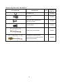
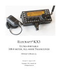
1
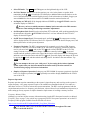
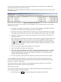
Elecraft® KX3 KX3-2M 2-Meter and KX3-4M 4-Meter Transverter Options Installation and Operating Instructions Revision A5, September 5, 2014 Copyright © 2014, Elecraft, Inc., All Rights Reserved Introduction ...................................................................................................................................... 2 Specifications ................................................................................................................................... 2 Setup and Operation ......................................................................................................................... 3 Configuring the KX3 for the KX3-2M or KX3-4M Module ..................................................................... 3 Antennas ..................................................................................................................................................... 3 Operation .................................................................................................................................................... 4 Frequency Stability ................................................................................................................................ 4 VHF Operating Frequencies ................................................................................................................... 4 KX3-2M/4M Tuning .............................................................................................................................. 5 FM Operation ......................................................................................................................................... 5 Basic Setup ......................................................................................................................................... 5 Repeater Operation ............................................................................................................................. 6 Sending DTMF Tones ........................................................................................................................ 9 Channel Hopping (Scanning) ............................................................................................................. 9 Monitoring the Repeater Input Frequency ......................................................................................... 9 Sleep Mode ....................................................................................................................................... 10 Troubleshooting .............................................................................................................................. 10 Circuit Description ......................................................................................................................... 11 Installing the KX3-2M or 4M Module ........................................................................................... 12 Preparing for Installation .......................................................................................................................... 12 Preventing Electrostatic Discharge Damage ........................................................................................ 12 Choosing an Anti-Static Mat ................................................................................................................ 12 Tools Required ......................................................................................................................................... 13 Parts Supplied ........................................................................................................................................... 13 KX3-2M or 4M Transverter Assembly Bag (E850580)....................................................................... 13 Adapter Board ...................................................................................................................................... 13 Hardware Bag, KX3-2M or 4M (E850635) ......................................................................................... 14 Installation Procedure ............................................................................................................................... 15 Separate the Case Halves ..................................................................................................................... 15 Install the Internal Coaxial Cables ....................................................................................................... 16 Installing the Antenna Coaxial Cable ............................................................................................... 17 Installing the Local Oscillator Coaxial Cable .................................................................................. 20 Prepare the KX3 for the KX3-2M or 4M Module ................................................................................ 23 Installing the KX3-2M or 4M Board .................................................................................................... 25 Customer Service and Support ....................................................................................................... 30 Technical Assistance ............................................................................................................................ 30 Repair / Alignment Service .................................................................................................................. 30 1 Introduction The KX3-2M or 4M transverter extends the frequency range of the KX3 to include the 2 meter or 4 meter Amateur bands and allows reception on frequencies near those bands. Either the 2-meter or the 4-meter transverter may be installed. The transverter plugs into existing connectors inside the KX3. All KX3 functions and modes are available when using either transverter. The KX3-2M or KX3-4M transverter uses a separate antenna connector that bypasses the KXAT3. CAUTION The KX3-2M or KX3-4M module and many components inside your KX3 may be damaged by Electrostatic Discharge (ESD) simply by touching them or a circuit board containing them unless you take specific steps to prevent such damage. If you are installing the KX3-2M or KX3-4M module yourself, see Preventing Electrostatic Discharge Damage on page 12 before opening the package containing the KX3-2M or KX3-4M module or working inside your KX3. Specifications General Transmit Frequency Range: KX3-2M: 144 MHz – 148 MHz KX3-4M: 69.9 MHz – 70.6 MHz (covers all known 4-meter frequency allocations) Receive Frequency Range: Power Consumption: KX3-2M: 120 MHz – 150 MHz, typical, with reduced sensitivity outside of 144-148 MHz KX3-4M: 65 MHz – 72 MHz, typical, with reduced sensitivity outside of 69.9-71 MHz. 120 mA receive, squelch open, typical, in addition to the normal KX3 current demand whenever the 2 meter or 4 meter band is selected. Sleep Mode (see page 10) can reduce the overall radio current to about 150-180 mA in FM Mode (squelched). 1.7 A at 3W output, total radio current, typical for the KX3 when transmitting on 2M or 4M. Receiver, 2M and 4M Sensitivity: MDS -144 dBm, typical, at 500 Hz bandwidth. Transmitter, 2M and 4M Output Power: 2.5 W Minimum with 13.8 Vdc supply (2.5 to 3 watts typical) 2 W Maximum with 11 Vdc supply 1.5 W Maximum with 9 Vdc supply 2 Setup and Operation If you haven’t already done so, follow the instructions starting on page 12 to install the KX3-2M or KX34M module. Before you can use the KX3-2M or KX3-4M module, you must configure the KX3 as follows. Configuring the KX3 for the KX3-2M or KX3-4M Module Attach power to the KX3 and tap B AN D – and AT U T U N E switches simultaneously to turn it on. With the KX3 on, hold the M E N U switch to enter the menu. Turn the VFO knob to FW REVS . The LCD will display the revision of the firmware installed. It must be uC 02.18 or later (a higher number). If not, download and install the latest firmware as described in the KX3 Owner’s manual under Firmware Upgrades. Turn the VFO knob to 2M/4M MODE and turn the VFO Turn the VFO knob to TECH MD and turn the VFO knob to nor. knob if needed to On. The remaining steps require you to unlock the VFO knob for each setting. Unlock the VFO knob by holding K H Z until UNLOCK appears briefly in the VFO B display area. A small padlock symbol in the upper right corner of the display will disappear when VFO is unlocked. Turn the VFO knob to XVn ON . n is the number of the transverter band you wish to assign to the internal 2M or 4M module. You can assign any number from 1 to 9 by tapping the 1 through 9 switches that you have not assigned to an external transverter. The default is 1. After entering the number turn the VFO knob to YES. In the following steps n is the transverter number you chose. Turn the VFO knob to XV n RF and turn the VFO 70 if installing the 4 meter module. knob to 144 if using the 2 meter module or Turn the VFO knob to XV n IF and turn the VFO if using the 4 meter module. knob to 50 if using the 2 meter module or 21 Turn the VFO Turn the VFO knob to XV n OFS and turn the VFO knob to 0.00. Offset is not used with the internal module. If there is a frequency error, use the REF CAL procedure in your KX3 Owner’s Manual. Turn the VFO Tap the M E N U switch to exit the menu. knob to XV n PWR and turn the VFO knob to XV n ADR and turn the VFO knob to H 3.0. knob to Int. trn0. (Continued on next page) 3 Turn the KX3 power off, then on again by tapping the B AN D – and AT U T U N E switches simultaneously for the changes to take effect. 1) Do not turn off your power supply. Always use the front panel switches to turn power on and off. Although disconnecting your external power supply when no batteries are installed in the KX3 will often cause no harm, certain parameter changes may not be saved and it is possible to corrupt some data that could require you to reload the firmware. After cycling power hold M E N U to re-enter the menu and then turn the VFO knob to BND MAP. Tap the B AN D – and B AN D + switches as needed to display 144 for the 2 meter module or 70 for the 4 meter module and then turn the VFO knob, if needed, to display In. Tap the M E N U switch to exit the menu. Antennas Connect your 2 or 4 meter antenna to the female SMA connector mounted on the KX3’s right end plate. Note that when you select the 2 or 4 meter bands, ANT2 appears on the LCD indicating that the SMA connector is in use (see Figure 1 on page 5). The BNC connector is used only for the 160 through 6 meter bands. The antenna system must present a load very close to 50 ohms (have a low SWR) for full power output and efficient operation. The KXAT3 Automatic Tuner option, if installed, does not function on 2 or 4 meters. The 2 or 4 meter RF output is completely separate from the KXAT3 signal path. Antenna polarization (vertical or horizontal) has more effect on signal strengths in the VHF range than it does on the HF bands. Vertical polarization is normally used for FM communications to match the polarization of mobile whips and ‘rubber duck’ antennas on hand held radios. Horizontal polarization is most common for SSB, AM, CW and Data modes. Operation Complete operating information is included in your KX3 Owner’s Manual. The following is specifically to help you get the most from your KX3-2M or KX3-4M in FM mode. Additional information about your KX3-2M or 4M may be found in the FAQ on the Elecraft web site: http://www.elecraft.com/manual/KX3-2M%20FAQ.htm Frequency Stability The standard (uncompensated) frequency stability is sufficient for FM or AM operation. For CW, SSB or Data use, it will be necessary to perform the KX3 extended VFO temperature compensation procedure, providing typical stability of about ± 10 Hz on 2 or 4 meters. This is compatible with 170-Hz-shift RTTY but may not be compatible with some narrowband modes such as JT65 or WSPR. The extended temperature compensation procedure is available on the Elecraft web site: http://www.elecraft.com/manual/KX3%20Custom%20VFO%20TC%20rev%20A9.pdf VHF Operating Frequencies The VHF bands are typically organized by operating mode and type of communications, with frequencies set aside for beacons and sub bands reserved for weak-signal work to avoid interference from local stations. Also, frequencies are set aside for FM communications along with input-output frequency pairs for FM repeaters to avoid interference with other modes. More information about the band plans can be found at www.70mhz.org for 4-meter operation and www.arrl.org/band-plan for 2-meter operation. 4 KX3-2M/4M Tuning Tap the B AN D + or the B AN D ˗ switch to select the 2 or 4 meter band, depending upon which transverter you have installed. As on HF, the KX3 tuning can be done using direct frequency entry or with the VFO knobs. For FM communications you may find tuning more convenient to switch the tuning rate to 5 kHz steps: hold K H Z to switch the tuning rate. Tap R AT E to restore finer tuning steps. This tuning rate is determined by the VFO CRS setting in the menu. It is per-mode and can be set to a convenient value for each mode using the menu. The default values are 5 kHz in FM mode, 500 Hz in SSB (USB or LSB), 100 Hz in CW and 1 kHz in AM. See VFO CRS under Menu Functions in your KX3 Owner’s Manual for information about changing the default step sizes. To make a direct frequency entry, tap F R E Q E N T , then enter 1 to 3 MHz digits, a decimal point, and 0 to 3 kHz digits, followed by tapping . . . (Note that the 7, 8 and 9 number switches are activated by tapping the AF / R F - S Q L , P B T I / I I , and K E Y E R / M I C encoder knobs.) The following sections describe how to store frequencies in memory for quick QSY. For repeater operation the PL tones and offsets are also stored so you can switch to a repeater channel and be ready to communicate with a few simple key presses. Also you can have the KX3 scan preselected channels stored in memory and monitor a second frequency, such as a repeater input frequency, for activity. FM Operation Figure 1 shows the KX3 LCD identifying only those elements mentioned in the this text. See your KX3 Owner’s manual for a complete description of the display. Figure 1. KX3 Display. Basic Setup Set up your KX3 for FM operation on 2 or 4 meters as follows. Enable FM mode as follows. This need be done only once. FM mode will remain on unless you re-enter the menu and turn it off. o Hold M E N U . o Turn the VFO o Tap M E N U to exit the menu. knob to FM MODE and turn the VFO 5 knob to On. Select FM mode: Tap M O D E until FM appears on the right hand edge of the LCD. Set Voice Monitor Level: If you wish to monitor your voice in the phones or speaker while transmitting, hold M O N to switch the VFO B display to MON and then turn the knob to set the level of the audio between 1 and 30. High levels may result in distortion or feedback. Suggest you start with MON 5 or less as shown on the LCD. MON 0 turns the monitor function off. Set Display to CMP/ALC: If the bargraph indicates SWR/RF tap the switch the display to CMP/ALC. KEYER/MIC control to Be sure you have a suitable antenna or dummy load connected to the SMA antenna connector when making the following transmitter adjustments. Set Microphone Gain Level: Press the microphone PTT switch and, while speaking normally into the microphone, adjust the KEYER/MIC control for 5 or 6 bars indicated on the LCD ALC display as shown in Figure 1. Set RF Power Output Level: Exit transmit mode, and hold P W R . The output power setting will be displayed in the VFO B area of the LCD. Adjust the knob for the desired output power, and then tap the knob to exit the power adjustment. Frequency Deviation: The KX3 is programmed with commonly used values of FM frequency deviation (3.5 kHz for voice and 0.36 kHz for PL tone used by repeaters). If different values are used in your area, hold M E N U and use the VFO knob to locate FM DEV on the LCD. This setting is locked to avoid accidental changes. Unlock the control by holding K H Z for several seconds until the padlock symbol to the right of the deviation value shown on the LCD disappears, and then set the desired deviation with the VFO knob. If needed, display and change the PL tone by tapping the 1 switch, and then unlock and change the PL deviation in the same manner. Tap M E N U to exit the menu. Do not attempt to increase your “talk power” by increasing the deviation. Optimum results require that your deviation match the deviation used by the other station. See Troubleshooting on page 10 for more information. Simplex or Repeater Operation: Setting up your KX3-2M/4M for repeater operation is described below. For Simplex operation, hold AL T repeatedly as needed to display SIMPLEX in the VFO B area of the LCD. Repeater Operation Repeater operation requires transmitting on the repeater’s input frequency and receiving on the repeater’s output frequency. Also, many repeaters require a sub-audible tone transmitted with the voice audio or a short burst of tone at 1750 Hz to activate the repeater transmitter. The KX3 can be programmed with the required transmit and receive frequency pairs and tones, selected from a list of standard tone frequencies, to make setting up for any repeater or simplex channel a simple matter of recalling a memory location. Frequency Memory Editor Although you can enter all the necessary information using just the KX3 front panel controls (see Manual Frequency Entry on page 7), the easiest way to program your KX3 for repeater operation is to use the K3 Frequency Editor program available from the Elecraft web site at: http://www.elecraft.com/K3/FreqMemEdit/K3_Freq_Mem_Editor.htm Note that the editor refers to the Elecraft K3 transceiver throughout. The same editor is used with the KX3. 6 To use the editor, connect your computer to the KX3 using the same serial cable you use with the KX3 Utility Program and select the active comm. port. The editor uses a simple spreadsheet format. Figure 2 shows a typical frequency editor screen with 2-meter FM repeater entries. Figure 2. Frequency Editor Screen. Initially the Offset and PL Tone columns will not be displayed. They will appear when you select FM as the mode for any entry ID column: The memory location number. The number will be displayed on the KX3 LCD when the memory is recalled. Up to 100 frequencies can be entered (00-99). Label: User selected up to 4 characters long. The asterisk (*) has special significance for scanning the channels entered to check for activity. See Channel Hopping (Scanning) on page 9 for details. Description: You can enter up 23 characters to identify the use of the frequency. This data is not displayed at the KX3. QSY: Clicking the radio button while the KX3 is connected to the computer switches to KX3 to the band and frequency shown. Also, you can switch to any memory at the KX3 without using the computer. Hold R C L to display the frequency memories in the VFO B area of the LCD. Turn the VFO knob to step through the memory locations. The KX3 will shift to each frequency as each memory location is selected. VFO A: The repeater output frequency (KX3 receive frequency). Mode: Select FM for the Mode A and B columns. Offset: The offset is the difference between the repeater input and output frequencies. Choose the offset from the drop-down list. Be sure to choose the right sign. The offset is positive (+) if the repeater output frequency is above the input frequency and negative (-) if the repeater output frequency is below the input frequency. PL Tone: If required, choose the PL tone frequency from the drop down list for each repeater. Click on Send All to K3 when finished to store the data in the KX3 memories. Note that buttons are provided on the editor tool bar for reading existing memory information from the KX3 and for erasing memories, as a group or individually. Non-repeater entries are made in the same way but without showing an offset, just as you can enter frequencies for any other band or mode covered by the KX3. Manual Frequency Entry You can set up the KX3-2M or 4M for repeater or simplex operation and store the information in the KX3’s memory without a computer as follows: Select FM mode: tap M O D E as needed so FM appears on the right end of the LCD. 7 Enter the KX3 transmit frequency using the VFO knob or with direct frequency entry. For operation with a repeater this will be the repeater input frequency. For operation with a repeater, select the correct offset (difference between repeater input and output frequencies), offset direction (repeater input frequency above or below the output frequency) and the PL tone frequency (if needed) as follows: o The default offset is 600 kHz. You can check the value and change it as needed: hold M E N U and select RPT OFS with the VFO knob, and then use the VFO knob to select the correct offset value displayed in kHz. Tap M E N U to exit. o Hold AL T repeatedly as often as needed until TX + X.XX appears on the LCD VFO B area if the repeater input frequency (KX3-2M or 4M transmit frequency) is higher than the repeater output frequency or until TX – X.XX appears if the repeater input frequency is lower than the repeater output frequency. The X.XX is the offset (difference between repeater input and output frequencies) that you entered above. The + or – sign, indicating the direction of the repeater offset, will appear below FM on the LCD. Be sure you select the correct sign ( + or – ) that corresponds to the direction of the repeater offset. If you selected the wrong sign, you can change it by holding REV. o If the repeater requires a PL tone, hold P I T C H . The VFO B area of the LCD will show PL OFF or PL X.XX, where X.XX is the PL tone frequency. This is a toggle that alternates between tone off and tone on. To change the PL tone frequency, turn the KEYER/MIC knob to step through the standard tone frequencies. Tap M E N U to exit. Selecting the 1750 Hz PL tone frequency adds a 0.5 second tone burst to the beginning of each transmission (for European repeaters). Holding P I T C H while transmitting extends the tone indefinitely. Hold S T O R E and then use the VFO knob to locate the desired memory location shown in the VFO B area of the LCD. Hold S T O R E again or tap any switch to cancel. To recall previouslysaved data, hold R C L (recall) and use the VFO knob to select the desired memory location. Tap any switch to exit. If desired, add labels to each memory location or edit an existing label as follows: o Hold R C L (recall) and use the VFO o Turn the VFO knob. A cursor will appear to the right of the memory number on the LCD. If no label has been stored before, a series of dashes indicating the 5 available character locations will appear. o Turn the VFO knob to step through the available characters (A-Z, 0-9 and various symbols) to choose the first character. o Hold S T O R E to store the label. knob to select the desired memory location. 8 Sending DTMF Tones The KX3 can generate the Dual-Tone Multi-Frequency (DTMF) tones required to activate special services available through many repeaters. Press and hold the PTT to transmit. Tap F R E Q E N T . DTMF ON will appear in the VFO B area of the LCD. Press the following keys to enter the needed characters. The tone will continue as long as each key is pressed. To disable the DTMF keys, release the PTT or tap F R E Q E N T . Character Press 0 – 9 Numbered keys * AT U T U N E # MSG A MODE B A/ B C D AT A D A> B Channel Hopping (Scanning) Scanning or manually tuning across a group of frequencies stored in memory is referred to as channel hopping. This is especially useful to monitor repeaters and specific simplex frequencies. Set up the KX3 for channel hopping as follows: Store all of the frequencies you want to monitor in successive memory locations anywhere between 0 and 99 with an asterisk (*) as the first character of each label. Note that these memory locations must be successively numbered locations with no gaps and all of the frequencies must be within the same band. You can include frequencies within the band that use different modes such as SSB, AM or CW. Tune to any one of the memorized locations by holding R C L (recall) and turning the VFO knob to select one of the memory locations or by clicking on the QSY radio button in the Frequency Editor while it is connected to the KX3. Turn the VFO knob to step the KX3 through the frequencies in the memory locations or press to initiate a live scan across those frequencies. Tap any switch to stop the live scan. S C AN Tap R AT E or change bands to disable channel hopping. Monitoring the Repeater Input Frequency The KX3 allows you to quickly check the repeater input frequency (your transmit frequency) to check for interference. With the KX3 ready to transmit on a repeater, hold R E V . The VFO A display will switch to the repeater input frequency and you will hear any audible signals present. Hold R E V again to return to normal operation. Be sure you hold R E V a second time to switch back to normal operation before transmitting. 9 Sleep Mode Sleep mode allows you to reduce the added current drain of the 2M or 4M module by up to 50% while monitoring a frequency with the receiver squelched. The 2M or 4M module is switched off and reawakened at intervals to check for any activity on the frequency. Hold M E N U and then select 2M/4M with the VFO always on). Use the VFO knob to select the desired time in seconds between checks for a signal: SLEEP .25, .50, .75 or 1.0. For example, SLEEP .50 means the KX3 will wake up and check the frequency for knob. The default setting is nor (receiver a signal every half (0.5) second. Troubleshooting General KX3 troubleshooting suggestions are included in the KX3 Owner’s manual. The most common symptoms and their causes relating to the KX3-2M or KX3-4M modules are listed below. If the problem persists, contact Elecraft Customer Support (page 30) or post a question on the Elecraft e-mail reflector. Be sure you completed all of the settings under Configuring the KX3 for the KX32M or KX3-4M Module on page 3. No FM output: Verify that FM Mode enabled in menu: Hold M E N U , turn the VFO knob to On. MODE and turn the VFO RF Output Decreases After Short Transmission or Poor Receive Sensitivity: Ensure the screw securing the 2M or 4M module to the KX3 end plate is in place and snug (see Figure 22 on page 28). You will need to open the KX3 as if you were changing batteries to see the screw. This screw is essential to avoid overheating the power output transistor in the 2M or 4M module. You can monitor the temperature change while transmitting. Tap D I S P L AY and turn the VFO knob to display PA.2 in the VFO B area of the LCD. The temperature is shown in Celsius. VFO Tuning Noise Heard in Speaker or Phones: Hold M E N U , turn the VFO knob to VFO NR (VFO Noise Reduction) and turn the VFO knob to On. Optionally, in the menu set RX SHFT to 8.0. Even with these settings, there may be very weak noise heard. If your KX3 is equipped with the KXFL3 roofing filer and was purchased prior to January 2014, check to be sure the KXFL3 board was modified as described in the Elecraft KX3 VFO Tuning Noise Suppression Modification document available on the Elecraft web site. Weak or Distorted Audio in FM Mode: Check for proper microphone gain level. Press the microphone PTT switch and, while speaking normally into the microphone, adjust the KEYER/MIC control for 5 or 6 bars indicated on the LCD ALC display as shown in Figure 1. Check that your deviation matches the receiving station (or repeater). For optimum results the deviation used at the transmitting station must match the deviation expected by the receiving station. If the deviation is too low the audio may sound weak. If the deviation is too high, the audio may be broken up and distorted. See Frequency Deviation on page 6 if you need to adjust the deviation. Unable to Access Repeaters: If you are sure you are in a location where your signal should bring up the repeater, check to ensure you are using the correct PL tone, that the PL tone is enabled for transmit and that the offset and offset sign are correct (see Repeater Operation starting on page 6). Be sure the Offset shown on the display (see Figure 1on page 5) is correct for the repeater. 10 knob to FM Unable to Hold Repeater While Transmitting: The most common cause is a weak signal. But if you are sure you are in an area where your signal should be strong at the repeater, over deviation may cause the repeater to shut off. Check with the repeater operator to determine the proper deviation for your voice and for the PL tone or tone burst (if used). If needed adjust the KX3 deviation as described under Frequency Deviation on page 6. Note that there are separate adjustments for voice and PL or tone burst deviation. Wattmeter: The wattmeter is calibrated at the factory. If you feel you have a more accurate lowpower VHF wattmeter or spectrum analyzer and an accurate VHF 50-ohm dummy load, you can adjust the wattmeter calibration. To adjust the wattmeter, hold M E N U and then turn the VFO knob to WMTR XV (transverter wattmeter). Note the default value in case you decide to return to it. Hold KHZ until UNLOCK appears briefly in the VFO B display area and turn the VFO knob to change the wattmeter reading. Turn the knob counter-clockwise to increase the power output or clockwise to decrease the power output. Transmit to see the change and repeat as needed. Circuit Description The KX3-2M transverter operates at an I.F. frequency in the 48 MHz range while the KX3-4M transverter operates at an I.F. frequency in the 23 MHz range. J1 connects the I.F. signals to the KX3. The IF signal passes through a low-pass filter to a CMOS SPDT switch. When transmitting, the CMOS switch passes the I.F. signal through an attenuator (approximately 25 dB). The attenuator allows the KX3 to operate at drive levels high enough to provide accurate power metering. The CMOS switch bypasses the attenuator when receiving. A high-performance double-balanced mixer converts the I.F. to the 2M or 4M band using a local oscillator signal supplied by the KX3 via J4. High-side injection is used on 2 meters, so when the KX3 VFO is set to 144 MHz indicated on the display, the local oscillator frequency is 192 MHz to produce an I.F. frequency in the 48 MHz range. Similarly, high-side injection is used on 4 meters (70 MHz) to produce an I.F. frequency in the 23 MHz range. Another single-pole double-throw CMOS switch connects the mixer to the transmit or receive signal path. In transmit mode, the signal passes through three stages of amplification and then on to the antenna connector J3 through a diode antenna switch and a low-pass filter. The diode antenna switch uses two diodes connected so that when one is forward biased to pass the signal, the other is reverse biased to block the signal. Switching the bias connects the antenna to either the transmit or receive signal path. In receive mode, the signal from the antenna connector is routed through the antenna switch to a low-noise amplifier and then through the single-pole, double throw CMOS switch to the mixer. The mixer converts the incoming signal to the I.F. and passes it directly to the next CMOS switch, bypassing the transmit signal attenuator, and then on to I.F. connector J1. 11 Installing the KX3-2M or 4M Module Preparing for Installation Preventing Electrostatic Discharge Damage ESD damage may occur with static discharges far too little for you to notice. A damaged component may not fail completely at first. Instead, the damage may result in below-normal performance for an extended period of time before you experience a total failure. We strongly recommend you take the following anti-static precautions (listed in order of importance) to ensure there is no voltage difference between the components and any object that touches them: Leave the KX3-2M or 4M PC board in its anti-static packaging until you install it. Wear a conductive wrist strap with a series 1-megohm resistor that will constantly drain off any static charge that accumulates on your body. If you do not have a wrist strap, touch a ground briefly before touching any sensitive parts to discharge your body. Do this frequently while you are working. You can collect a destructive static charge on your body just sitting at the work bench. WARNING DO NOT attach a ground directly to yourself without a current-limiting resistor as this poses a serious shock hazard. A wrist strap must include a 1-megohm resistor to limit the current flow. If you choose to touch an unpainted, metal ground to discharge yourself, do it only when you are not touching live circuits with any part of your body. Use a grounded anti-static mat on your work bench (see below). If you pick up a PC board that was not placed on an anti-static mat or in an anti-static package, touch first a ground plane connection on the board such as a connector shell or mounting point. If you use a soldering iron to work on a circuit board, be sure your iron has an ESD-safe grounded tip tied to the same common ground used by your mat and wrist strap. Choosing an Anti-Static Mat An anti-static mat must bleed off any charge that comes in contact with it at a rate slow enough to avoid a shock or short circuit hazard but fast enough to ensure dangerous charges cannot accumulate. Typically, a mat will have a resistance of up to 1 Gigaohm (109 ohms). Testing a mat requires specialized equipment, so we recommend that you choose an anti-static mat that comes with published resistance specifications and clean it as recommended by the manufacturer. Testing has shown that many inexpensive mats that do not specify their resistance have resistance values much too high to provide adequate protection, even after they were cleaned and treated with special anti-static mat solutions. Suitable anti-static table mats are available from many sources including: U-line (Model 12743 specified at 107 ohms) Desco (Model 66164, specified at 106 to 108 ohms) 3MTM Portable Service Kit (Model 8505 or 8507, specified at 106 to 109 ohms) 12 Tools Required 1. ESD Protection (see Preventing Electrostatic Discharge Damage, page 12). 2. #1 size Phillips screwdrivers. To avoid damaging screws and nuts, a power screwdriver is not recommended. 3. Long Nose Pliers. 4. Soft cloth or clean, soft static dissipating pad to avoid scratching the enclosure. 5. Optional: 5/16” wrench for tightening the antenna connector nut (see Figure 11 on page 19). Parts Supplied Be sure you have the following components in your kit. If anything is missing, contact Elecraft customer support (page 18). KX3-2M or 4M Transverter Assembly Bag (E850580) ILLUSTRATION DESCRIPTION QTY. Printed Circuit Board ESD SENSITIVE! Leave it in its anti-static envelope until it is installed. ELECRAFT PART NO. KX3-2M E850580 1 KX3-4M E850648 Shield Label will be checked to indicate whether the module is for 2M or 4M. 1 E850636 Adapter Board The adapter board is required only if your KX3 is not with the KXAT3 Antenna Tuner option. ILLUSTRATION DESCRIPTION KX3-2M or 4M Adapter Board 13 QTY. ELECRAFT PART NO. 1 E850633 Hardware Bag, KX3-2M or 4M (E850635) QTY. ELECRAFT PART NO. Lock Washer, #4 4 E700004 Spacer, M-F 2 E700304 Screw, Pan Head, Stainless Steel, 4-40, 5/32” (4.0 mm) 2 E700302 Screw, Flat Head 1 E700253 Coaxial Cable, Local Oscillator 1 E980255 1 E850634 ILLUSTRATION DESCRIPTION KX2-M Antenna Cable Assembly The connector on your cable may look different from that shown. 14 Installation Procedure The KX3-2M or 4M module mounts over the exposed area of the RF board in the bottom cover next to the battery holders. It mounts above the KXAT3 Antenna Tuner. An adapter board is included in the kit for those KX3s that do not have the optional Antenna Tuner. Figure 3. KX3-2M or 4M Module Installed in the KX3. Separate the Case Halves Disconnect all cables attached to the KX3 and remove the KXPD3 paddles if installed. Open the KX3 just as you would to install or remove batteries (see Internal Batteries in your Owner’s Manual for details about how to do this). Remove the internal batteries (if present). We recommend removing the batteries whenever you work inside of your KX3 to avoid damage that may be caused by an accidental short circuit. 15 Separate the two halves of the KX3 case by unplugging the battery cable and unplugging the flex cable at the end next to the battery holders as shown in Figure 4. Gently lift up on each end of the flex cable connector and rock it side to side to unplug it. When free, set the front panel assembly aside. Figure 4. Disconnecting the Flex and Battery Cables. Install the Internal Coaxial Cables Two miniature coaxial cables are used to carry RF signals. One cable carries a local oscillator signal from the KX3 main RF board to the KX3-2M or 4M module. The second cable carries RF signals between the KX3-2M or 4M module and an SMA antenna connector mounted on the end panel of the KX3 near the BNC antenna connector. The coaxial cables are equipped with female Ultra Miniature Coaxial (UMC) connectors that snap onto male UMC connectors on the KX3 RF board and the KX3-2M or 4M module (see Figure 5). Figure 5. Miniature Coaxial Connectors. 16 Installing the Antenna Coaxial Cable Remove the KXAT3 Antenna Tuner board as follows. If your KX3 is not equipped with the KXAT3, skip the following steps and go directly to installing the antenna cable on page 18. On the KXAT3 module, unplug the connector for the cable leading to the BNC connector as shown in Figure 6. You can use long-nose pliers to grip the connector as shown in Figure 7. If using the pliers, take care not to damage the pc board or components. Remove the two screws and lock washers shown in Figure 6. Lift the KXAT3 board out, unplugging it from the two connectors shown in Figure 6. Set the KXAT3 board aside in an ESD-safe place. Figure 6. Removing the KXAT3 ATU. 17 Figure 7. Using Long-Nose Pliers to Grip the H.F. Antenna Wire. Install the antenna coaxial cable and SMA connector as follows: Remove the plastic plug from the hole in the end of the KX3 enclosure near the BNC connector. This is most easily done with your long-nose pliers. Figure 8. Removing the Hole Plug. Check the inside surface of the KX3 end panel. The surface should be clean metal free of paint or masking tape as shown in Figure 8. This is important to provide a good ground for the antenna connector and good contact for the KX3-2M or 4M module power transistor heat sink. In the unlikely event you need to clean the metal surface, hold the KX3 with the end downward so any debris from the cleaning will not fall on to the PC board. Check the inside surface of the hole from which you removed the plug (Figure 8). The inside edge must be free of paint or tape; otherwise the antenna connector will not fit. If needed scrape the surface clean, taking care not to scratch the outside surface of the end panel or allow debris to fall inside the KX3 18 Locate the miniature coaxial cable with the SMA connector at one end. If the connector has a nut and lock washer on it (see Figure 9), remove only the nut, sliding it down and off the end of the coax. If your connector does not have the nut and lock washer on it, locate them in the hardware bag and slide the lock washer onto the connector. If the nut turns stiffly due to the solder at the end of the threaded section, thread it on and off again several times so it turns very smoothly. That will make the installation of the connector easier in the following the steps. Figure 9. Preparing the SMA Connector for Installation. One side of the SMA connector is flat. When you install it in the next step, align the flat side of the connector with the flat side of the D-shaped hole in the end panel. Thread the coaxial cable through the hole in the end panel that was occupied by the plug you removed. Before fitting the connector through hole in the end panel, slide one lock washer and the nut over the coax until they rest in the gap at the end of the PC board as shown in Figure 10 and then start the nut onto the SMA connector threads as you slide it through the hole. Be sure the connector does not touch L43 or L40 on the KX3 RF board. If needed, move the inductors slightly to provide clearance as shown in Figure 11. There is a solder-filled via on the RF board directly under the connector. That via is a ground connection between the top and bottom of the RF board so it doesn’t matter if it touches the SMA connector. Figure 10. Installing the SMA Antenna Connector. 19 Figure 11. Positioning L40 or L43 to Provide Clearance. Installing the Local Oscillator Coaxial Cable If your KX3 is equipped with the optional KXFL3 Filter option, remove the KXFL3 board as shown in Figure 12. Set it aside in an ESD-safe place. CAUTION Do not press on the large rectangular gray capacitors. Doing so may detune the filter and require that you re-align it as described in the KXFL3 manual when it is reinstalled. Figure 12. Removing the KXFL3 Filter option board. 20 Install the local oscillator cable as follows: If you have difficulty with the following steps to mate the ultra miniature coax connectors, a short video is available on the Elecraft web site at: http://www.elecraft.com/KX3/kx3.htm. Scroll down to UMCC Connector Montage near the bottom of the web page. Locate the coaxial cable with a miniature connector on each end. Plug one end of the cable into J4 on the KX3 RF board as follows: Shape the end of the cable as shown in Figure 13 to it can be easily placed directly onto J4. Carefully align the cable over the connector and press down on the connector. It will require significant force to mate the connectors, especially when they are new. Press on the connector directly over J4 using a plastic tool such as a pen (see Figure 14) .Take care to press directly on the back of the connector above J4. You will hear and feel a distinct “snap” when they are mated and, of course, the connector will resist being pulled off of J4. Figure 13. Mating the Ultra Miniature Coaxial Connector at J4. Turn the coaxial connector as shown in Figure 14 so the metal part cannot touch C180 on the printed circuit board. If the connector is properly mated you can rotate it without the connector disconnecting. Route the coaxial cable toward the end of the KX3 that has the antenna connector as shown. 21 Figure 14. Orienting the Cable at J4.. If you removed the KXFL3 filter board (see Figure 12 on page 20), replace it now. Replace the retaining screw and ensure it passes into the hole in the KXFL3 board. 22 Prepare the KX3 for the KX3-2M or 4M Module The KX3-2M or 4M PC board mounts on top of the KXAT3 Antenna Tuner board. If you do not have the KXAT3 option installed, your kit will include an adapter board to install in place of the KXAT3. If you do not have the KXAT3 Antenna Tuner installed, disconnect the HF antenna cable from the main RF board as shown in Figure 15. Figure 15. Disconnecting the Antenna Cable from the Main RF Board. Route the antenna coax cable across the RF board, between the toroidal inductors and alongside the standoff exactly as shown in Figure 16. Figure 16. Routing the Antenna Coax. 23 Replace the KXAT3 board as shown in Figure 17 or, if your KX3 is not equipped with the KXAT3 Antenna Tuner option, install the adapter board furnished in its place. Do not disturb the location of the antenna coax you just positioned. There are two multi-pin connectors on the KXAT3 or on the adapter board. Be sure they are properly mated with the corresponding connector(s) on the RF board below as shown in the figure. Reconnect the HF antenna cable. The two pins are tied together electrically so the connector may be inserted with the pins oriented either way. Secure the KXAT3 or adapter board using the two M-F standoffs and lock-washers. Place the lock washers under the standoffs as shown in Figure 18. CAUTION Tighten the M-F standoffs only enough to compress the lock washers. The standoffs are aluminum and you can easily twist the threaded shaft off of the rest of the standoff. Figure 17. Replacing the KXAT3 ATU. Figure 18. KXAT3 or Adapter Mounting Hardware. 24 Installing the KX3-2M or 4M Board Since attaching the coaxial connectors takes significant force, be careful not to damage the KX3-2M or 4M board or any of the components on it when attaching the cables to it. The connectors for the antenna and local oscillator coaxial cables are on the side of the board that faces downward toward the KX3 RF board when it is installed, so the coaxial cables must be attached first. The locations of the coaxial connectors on the KX3-2M or 4M board are shown in Figure 19. Note that the KX3-2M or 4M board has no components directly behind the coaxial connectors. That allows you to place a solid object behind the PC board to support it while pressing the coaxial cable connectors in place as described below. CAUTION Do not try to attach the coaxial cables without supporting the board to avoid stressing the board or the components. The connectors will require as much force as you used on the L.O. connector earlier. Failure to provide good support may destroy the KX32M or 4M board. Figure 19. KX3-2M or 4M Board Coaxial Connector Locations. 25 Attach the coaxial cables to the KX3-2M or 4M board as follows: Connect the local oscillator coaxial cable to the L.O. connector (J4) on the KX3-2M or 4M board using a solid object to support the board from behind while you press the connector in place with a tool such as a plastic pen just as you did before at L.O connector J4. Figure 20 shows a common pencil used to support the board but any solid support that rests directly against the printed circuit board and not the components on the board is suitable. Figure 20. Attaching the Local Oscillator Cable to the KX3-2M or 4M Board. 26 Connect the antenna coax to the ANT connector (J3) on the KX3-2M or 4M board as shown in Figure 21. Figure 21. Attaching the Antenna Coax to the KX3-2M or 4M Board. Install the KX3-2M or 4M board in the KX3 as follows: Mount the KX3-2M or 4M board on the KXAT3 Antenna Tuner board or, if no antenna tuner, the adapter board you installed earlier: Orient the board as shown in Figure 22. There are two multi-pin connectors that mate with connectors on the KXAT3 (or adapter) board. Be sure all the pins engage. Secure the KX3-2M or 4M board with three screws as shown in Figure 22. Use the stainless steel 5/16” (7.9 mm) pan head screws provided, not the black 3/16” (4.8 mm) pan head screws that were originally used to hold the KXAT3 board. CAUTION Be certain you install the black flat head screw that threads into the transistor heat sink. Failure to install this screw will cause the KX3-2M or 4M to shut down after a very short period of operation due to excessive heating of the final transistor. Tuck the local oscillator coax into the space between the heat sink and the battery holders.. 27 Figure 22. Mounting the KX3-2M or 4M Board in the KX3 If you have the KXAT3 installed, route the antenna coax to the KX3-2M or 4M board around the end as shown in Figure 23. Be sure the coaxial cable does not pass over either of the nearby toroidal inductors. Figure 23. Routing the Antenna Coax Between the KXAT3 Inductors Locate the notch on one side of the shield (see Figure 24). The notch is required to clear solder pads on the KX3-2M or 4M board. 28 Figure 24. Shield Notch Location. Place the shield over the metal frame on the KX3-2M or 4M board oriented as shown in Figure 25, and press it down so the small bumps on the frame are in the holes along all four sides of the shield. The bumps latch the shield in place. Do not operate your KX3-2M or 4M with the shield removed. It is required to provide essential isolation between circuits. Figure 25. Installing the Shield. Reassemble the KX3 enclosure (see Figure 4) Reconnect the ribbon cable. Reconnect the battery cable. Replace the batteries (if used). Close the case. That completes the installation of your KX3-2M or 4M module. 29 Customer Service and Support Technical Assistance You can send e-mail to [email protected] and we will respond quickly – typically the same day Monday through Friday. If you need replacement parts, send an e-mail to [email protected]. Telephone assistance is available from 9 A.M. to 5 P.M. Pacific time (weekdays only) at 831-763-4211. Please use email rather than calling when possible since this gives us a written record of the details of your problem and allows us to handle a larger number of requests each day. Repair / Alignment Service If necessary, you may return your Elecraft product to us for repair or alignment. (Note: We offer unlimited email and phone support, so please try that route first as we can usually help you find the problem quickly.) IMPORTANT: You must contact Elecraft before mailing your product to obtain authorization for the return, what address to ship it to and current information on repair fees and turnaround times. (Frequently we can determine the cause of your problem and save you the trouble of shipping it back to us.) Our repair location is different from our factory location in Aptos. We will give you the address to ship your kit to at the time of repair authorization. Packages shipped to Aptos without authorization will incur an additional shipping charge for reshipment from Aptos to our repair depot. Elecraft 1-Year Limited Warranty This warranty is effective as of the date of first consumer purchase (or if shipped from the factory, the date the product is shipped to the customer). It covers both our kits and fully assembled products. For kits, before requesting warranty service, you should fully complete the assembly, carefully following all instructions in the manual. Who is covered: This warranty covers the original owner of the Elecraft product as disclosed to Elecraft at the time of order. Elecraft products transferred by the purchaser to a third party, either by sale, gift, or other method, who is not disclosed to Elecraft at the time of original order, are not covered by this warranty. If the Elecraft product is being bought indirectly for a third party, the third party’s name and address must be provided at time of order to ensure warranty coverage. What is covered: During the first year after date of purchase, Elecraft will replace defective or missing parts free of charge (post-paid). We will also correct any malfunction to kits or assembled units caused by defective parts and materials. Purchaser pays inbound shipping to us for warranty repair; we pay shipping to return the repaired equipment to you by UPS ground service or equivalent to the continental USA and Canada. For Alaska, Hawaii, and other destinations outside the U.S. and Canada, actual return shipping cost is paid by the owner. What is not covered: This warranty does not cover correction of kit assembly errors. It also does not cover misalignment; repair of damage caused by misuse, negligence, battery leakage or corrosion, or builder modifications; or any performance malfunctions involving non-Elecraft accessory equipment. The use of acidcore solder, water-soluble flux solder, or any corrosive or conductive flux or solvent will void this warranty in its entirety. Also not covered is reimbursement for loss of use, inconvenience, customer assembly or alignment time, or cost of unauthorized service. Limitation of incidental or consequential damages: This warranty does not extend to non-Elecraft equipment or components used in conjunction with our products. Any such repair or replacement is the responsibility of the customer. Elecraft will not be liable for any special, indirect, incidental or consequential damages, including but not limited to any loss of business or profits. 30