1
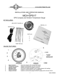
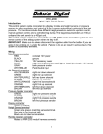
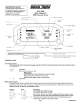
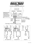
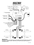
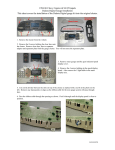
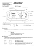
CMD-2000 SERIES REV A
REMOTE UP/DOWN DUAL WINDOW CONTROL
OR LOCK/UNLOCK CONTROL
INTRODUCTION
Thank you for purchasing the CMD-2000 series Remote Window Control from Dakota
Digital, Inc. This, along with many other products that Dakota Digital, Inc. has to offer, represents
the latest in electronics technology for the street rod, classic car and truck, and any custom
vehicle.
The CMD-2000 Remote Window Control system comes complete with receiver, two key
chain transmitters, wiring harness, two dual relay packs, and emergency release switch. An
emergency release switch can be concealed on the underside of the vehicle should the door ever
be closed with the transmitters inside and you on the outside. Pressing this button will allow
reentry to the vehicle.
INSTALLATION
While installation of the CMD-2000 is very straightforward, paying a little attention here and
planning out how the system will fit into your specific vehicle will save some time in the long run.
The receiver should be mounted under the dash up on the fire wall for best access to
wiring. The kick panel is also another good location for the receiver.
Connect the CMD-2000 system as is shown in the wiring diagram. While the wiring
diagram is self explanatory, there are several key areas to pay particular attention to. First, the 12
volt source to the relay packs should be able to supply up to 30 amps. This should have power
whether the key is on or off. The CMD-2000 should only be connected to a 12 volt battery for power
and never solely to a battery charger. The relay packs will typically be mounted inside the doors to
have the fewest wires running through the door jam. The relay packs should be mounted with the
wires exiting the bottom to prevent water from collecting inside the sockets.
ADDITIONAL TRANSMITTERS
The transmitters supplied with your remote system are serial number coded for security.
Each unit can “learn” up to 4 transmitters. It is also possible to program one transmitter into more
than one receiver. If you have more than one vehicle with the CMD-2000 system you can program
all of the transmitters into both units. Transmitters from other manufacturers, such as car alarm
systems, will not work with the CMD-2000.
MAN# 650016
1
DAKOTA DIGITAL
ANTENNA,
DO NOT GROUND
not used
not used
GROUND
CH 1
CH 2
in-line FUSE
All channels must
be connected to
relays if they are
used.
CHANNEL 2
CHANNEL 1
RED: +12 BATTERY
BLUE
GREEN
CHANNEL 3
CHANNEL 4
BLACK: GROUND
PINK
WHITE
YELLOW
CHANNEL 7
PURPLE
CHANNEL 6
BROWN
CHANNEL 5
Wiring harness color code.
GREEN
driver’s window up relay
RED
constant 12 volt battery source
BLUE
passenger’s window up relay
BLACK
chassis ground
WHITE
driver’s window down relay
YELLOW
passenger’s window down relay
PINK or GRAY
CHANNEL 7 relay (optional)
PURPLE
CHANNEL 6 relay (optional)
BROWN
CHANNEL 5 relay (optional)
The remote system output wires are negative switched outputs designed to turn on external
relays. These outputs can only handle 0.25 amps and must be used with a relay. Two dual relay
packs are supplied in the kit. To use all 7 channels you will need to purchase three additional
relays.
WINDOW CONTROL OPERATION
Each key chain transmitter has four buttons. Each button will activate its own independent
channel when pressed. Also, an additional 3 channels can be activated by pressing button 1 and
one of the other three buttons at the same time.
Button 1 activates the driver’s window up. The window will continue to move as long as the
button is held. Button 3 activates the driver’s window down.
Button 2 activates the passenger’s window up. Button 4 activates the passenger’s window
down.
Pressing buttons 1 and 2 at the same time can activate an external relay on Channel 5.
Pressing buttons 1 and 3 at the same time can activate an external relay on Channel 6.
Pressing buttons 1 and 4 at the same time can activate an external relay on Channel 7.
The emergency release switch can be wired to roll the driver’s window down to provide
emergency entry to the vehicle.
MAN# 650016
2
LOCK/UNLOCK OPERATION
Each key chain transmitter has four buttons. Each button will activate its own independent
channel when pressed. Also, an additional 3 channels can be activated by pressing button 1 and
one of the other three buttons at the same time.
Button 1 activates the door actuator to lock the doors. Button 3 activates the door actuator to
unlock the doors. The door actuator will remain powered for as long as the button is held. The
buttons should not be held more than a couple of seconds to avoid damaging the door lock
actuators.
Pressing button 2 can activate an external relay on Channel 2. This can be used for a trunk
latch release or other function.
Pressing button 4 can activate an external relay on Channel 4.
Pressing buttons 1 and 2 at the same time can activate an external relay on Channel 5.
Pressing buttons 1 and 3 at the same time can activate an external relay on Channel 6.
Pressing buttons 1 and 4 at the same time can activate an external relay on Channel 7.
Two additional wires will need to be passed through each door, along with the other power
window wires. This should be done using a flexible rubber tube or rubber grommet to protect the
wires, or by using the optional DAKOTA DIGITAL, INC. MAGNUM SHOOTERS. MAGNUM
SHOOTERS will eliminate the wires running through the door jambs entirely for the cleanest
appearance possible. When these highly conductive brass contacts are mounted to the door and
to the door jamb they eliminate the wires completely. If you would like to use MAGNUM
SHOOTERS they can be ordered directly from DAKOTA DIGITAL, INC. by calling toll free 1-800852-3228. Using either the flexible rubber tube, or MAGNUM SHOOTERS, route the remaining
wires under the dash for the best location and appearance.
MAN# 650016
3
WIRING DIAGRAMS
Wiring a relay for 12 volt accessories
Fused 12V power.
Do not
connect.
GREEN
87
BLUE
30
To 12 volt accessory.
RED
Fused 12V power.
WHITE
To CMD-2000 channel output.
86
85
BLACK
Using a dual relay pack to operate 12 volt accessories.
The blue wire can be used for one channel and the green wire for another channel.
Fused 12V power.
PURPLE
To 12 volt accessory.
BLUE
To 12 volt accessory.
GREEN
BROWN
Do not connect.
To CMD-2000
output.
BLUE
small wire Channel
WHITE
DUAL
RELAY
PACK
RED
FUSED 12V POWER
To CMD-2000
output.
GREEN
small wire Channel
MAN# 650016
4
5
GND
GND
+12V
BLACK
WHITE
GROUND-AT-REST
Switch - contact
positions vary
with style
WHITE
REGULATOR AND SWITCH
NOT INCLUDED
BLACK
BLACK TO SWITCH
WHITE
BROWN
GREEN
BLACK TO MOTOR
WHITE TO SWITCH
BLUE
PURPLE
CHASSIS
GROUND
CONSTANT-ON
FUSED +12V
WHITE TO MOTOR
TO CONSTANT-ON
FUSED 12V
WIRE COLORS COMING FROM
WINDOW REGULATOR MAY
VARY DEPENDING ON
MANUFACTURER.
Connection Ball's, GM,
Specialty, Dakota Digital,
Springfield Streed Rod,
and similiar power
window systems.
DUAL
RELAY
PACK
BLACK
RED
GREEN
small wire
RED
BLUE
small wire
DAKOTA DIGITAL
GREEN
CONSTANT-ON
FUSED 12V
WHITE
not used
not used
GROUND
CH 1
CH 2
MAN# 650016
BLUE
YELLOW
GREEN
small
wire
RED
BLUE
small
wire
GROUND
TAP INTO
WHITE
WIRE
FROM
REMOTE
DUAL
RELAY
PACK
SEALED
SWITCH
Driver's Window
Emergency Entry
Switch
WHITE
BROWN
GREEN
BLUE
PURPLE
ANTENNA,
DO NOT GROUND
TO PASSENGER SIDE
WINDOW REGULATOR
BLACK
6
CHASSIS
GROUND
POWER WIRES
DUAL
RELAY
PACK
BLACK
RED
WINDOW MOTOR WIRES
4-WIRE or 3-WIRE
NOT GROUND-AT-REST
SWITCH
WHITE
BROWN
GREEN
CHASSIS
GROUND
BLUE
BLACK
PURPLE
CHASSIS
GROUND
CONSTANT-ON
FUSED +12V
BLUE
TO CONSTANT-ON
FUSED +12V
DO NOT CONNECT
NOTE THAT +12V WIRE
ON POWER WINDOW SWITCH
IS NO LONGER CONNECTED.
CONNECTING A +12V WIRE
TO THE SWITCH WILL
DAMAGE THE REMOTE
CONTROL UNIT!
BLUE
REGULATOR AND SWITCH
NOT INCLUDED
Connection to
4-wire, center open
power window
switches.
GREEN
small
wire
RED
BLUE
small
wire
GREEN
CONNECT TO
CONSTANT-ON
FUSED +12V
WHITE
BLUE
RED
YELLOW
GROUND
TAP INTO
WHITE
WIRE
FROM
REMOTE
DUAL
RELAY
PACK
SEALED
SWITCH
Driver's Window
Emergency Entry
Switch
WHITE
BROWN
GREEN
BLUE
PURPLE
ANTENNA,
DO NOT GROUND
TO PASSENGER SIDE
WINDOW REGULATOR
DAKOTA DIGITAL
not used
not used
GROUND
CH 1
CH 2
MAN# 650016
POWER WINDOW
SWITCH
GROUND
SPLICE
REGULATOR AND SWITCH
NOT INCLUDED
7
DO NOT USE
DO NOT USE
TO CONSTANT-ON
FUSED +12V
TO CONSTANT-ON
FUSED +12V
Special regulator or
an additional relay module
required for this style
of wiring connection
WHITE
BROWN
GREEN
BLUE
PURPLE
CHASSIS
GROUND
CONSTANT-ON
FUSED +12V
DUAL
RELAY
PACK
BLACK
RED
GREEN
small wire
RED
BLUE
small wire
GREEN
CONNECT TO
CONSTANT-ON
FUSED +12V
WHITE
BLUE
GREEN
small wire
RED
BLUE
small
wire
DUAL
RELAY
PACK
SEALED
SWITCH
WHITE
BROWN
GREEN
BLUE
PURPLE
ANTENNA,
DO NOT GROUND
Driver's Window
Emergency Entry
Switch
GROUND
TAP INTO
WHITE
WIRE
FROM
REMOTE
YELLOW
DAKOTA DIGITAL
not used
not used
GROUND
CH 1
CH 2
MAN# 650016
TO PASSENGER SIDE
WINDOW REGULATOR
8
GROUND
+12V (BATT)
GROUND
5-WIRE
SWITCH
+12V BATTERY
GREEN
BROWN
WHITE
BLUE
PURPLE
GROUND
+12V BATTERY
Connection to door lock motors with a
5-wire switch.
BLACK
RED
GREEN
small wire
GREEN
RED +12V BATTERY
small wire
BLUE
WHITE
DAKOTA DIGITAL
not used
not used
GROUND
CH 1
CH 2
MAN# 650016
ANTENNA,
DO NOT GROUND
9
GROUND
+12V BATTERY
Connection to door lock motors
directly without a switch.
GREEN
BROWN
WHITE
BLUE
PURPLE
GROUND
+12V BATTERY
BLACK
RED
GREEN
small wire
GREEN
RED +12V BATTERY
small wire
BLUE
WHITE
DAKOTA DIGITAL
not used
not used
GROUND
CH 1
CH 2
MAN# 650016
ANTENNA,
DO NOT GROUND
10
DOOR LOCK
SWITCH
GND
+12V
GND
GROUND
+12V BATTERY
DO NOT CONNECT
+12V BATTERY
FACTORY DOOR
LOCK SYSTEM
BLACK
RED
Connection to factory door
lock motors with a 3-wire
switch.
GREEN
small wire
GREEN
RED +12V BATTERY
small wire
BLUE
WHITE
DAKOTA DIGITAL
not used
not used
GROUND
CH 1
CH 2
* wire colors listed in
( ) are for alternate
relay sockets found
in some units.
MAN# 650016
ANTENNA,
DO NOT GROUND
TECHNICAL SUPPORT
If you need any assistance with or have any questions about the wiring or operation of your CMD-2000 remote
system, please call the Dakota Digital technical assistance line at (605) 332-6513 or email us at
[email protected].
TRANSMITTER PROGRAMMING
All of the transmitters to be programmed into the system should be available. This sequence will erase any
previously programmed transmitters. If a transmitter is lost or stolen, go through the programming sequence with the
remaining transmitters and the lost one will be erased. The programming light (LED) is located on the side opposite
the antenna, next to the programming switch.
1. Press and release the programming switch 3 times. The LED should come on and remain on steady.
2. Press button 1 on the first remote. The LED should go out and then come back on steady.
3. Press button 1 on the second remote. The LED should go out and then come back on steady.
4. Repeat this for up to 4 remotes total.
5. When all of the remotes have been programmed in, wait for the LED to go out. The system will now operate
normally with all of the remotes.
wire harness
programming
switch
LED
BATTERY REPLACEMENT
Should the transmitter function become weak or erratic, the battery in the key chain transmitter may be weak. An
indication of a weak battery is that the red indicator may have a dim glow to it when either button is pressed. If this
occurs, first check the system by using the second transmitter provided. If the second transmitter functions properly,
replace the battery in the defective transmitter by the following method:
A. Use a small, flat screw driver or knife to pry the case apart next to the chain.
B. Carefully separate the two case halves.
C. Remove the battery noting the (+) and (-) position.
D. Replace the battery with a new 12 volt type GP23A battery which is available at most electronic stores (Radio
Shack, etc.).
E. Carefully replace the top cover snap it into place.
F. Check transmitter function.
SERVICE AND REPAIR
DAKOTA DIGITAL offers complete service and repair of its product line. In addition, technical consultation is available to help you work through any questions
or problems you may be having installing one of our products. Please read through the Troubleshooting Guide. There, you will find the solution to most problems.
Should you ever need to send the unit back for repairs, please call our technical support line, (605) 332-6513, to request a Return Merchandise Authorization
number. Package the product in a good quality box along with plenty of packing material. Ship the product by UPS or insured Parcel Post. Be sure to include the RMA
number on the package, and include a complete description of the problem with RMA number, your full name and address (street address preferred), and a telephone
number where you can be reached during the day. Any returns for warranty work must include a copy of the dated sales receipt from your place of purchase. Send no
money. We will bill you after repair.
Dakota Digital Limited Lifetime Warranty
DAKOTA DIGITAL warrants to the ORIGINAL PURCHASER of this product that should it, under normal use and condition, be proven defective in material or
workmanship for the lifetime of the original vehicle it was installed in, such defect(s) will be repaired or replaced at Dakota Digital’s option.
This warranty does not cover nor extend to damage to the vehicle’s systems, and does not cover removal or reinstallation of the product. This Warranty does
not apply to any product or part thereof which in the opinion of the Company has been damaged through alteration, improper installation, mishandling, misuse, neglect, or
accident.
This Warranty is in lieu of all other expressed warranties or liabilities. Any implied warranties, including any implied warranty of merchantability, shall be limited
to the duration of this written warranty. No person or representative is authorized to assume, for Dakota Digital, any liability other than expressed herein in connection with
the sale of this product.
MAN# 650016
11