1
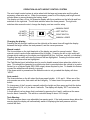
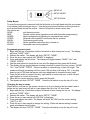
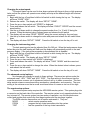
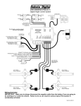
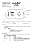
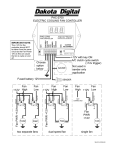
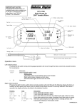
DHC-2000
Digital Height Control System
Introduction
This control system can be connected to a display module and height sensors or pressure
senders to allow monitoring and control of all four corners and optional monitoring of the tank
pressure. The functions include three different height presets for automatic up/down control,
manual up/down control, and a controlled bag dump. The bag pressure senders are 150 psi
units and the tank sender is a 400 psi unit.
This control system can also be connected to an ARR-2000 remote transmitter system to allow
remote control of the air bag system when the key is off.
IMPORTANT: Make sure to always disconnect the negative cable from the battery if you are
going to be working on or under the vehicle. Failure to do so can result in serious injury if the
system is accidentally activated.
Wiring
Main Power connector
RED
constant 12V power
BLACK
ground
YELLOW
12V accessory power
BLUE
night dimming (connect to tail light or head light circuit, +12V active)
GRAY
tank pressure sender
WHITE/BLUE
Park/Neutral input
Air Solenoid connector
WHITE/GREEN
right rear down solenoid
GREEN
right rear up solenoid
WHITE/PURPLE
left rear down solenoid
PURPLE
left rear up solenoid
WHTE/ORANGE right front down solenoid
ORANGE
right front up solenoid
WHITE/BROWN
left front down solenoid
BROWN
left front up solenoid
Pressure Sender connector
GREEN
right rear pressure sender
PURPLE
left rear pressure sender
ORANGE
right front pressure sender
BROWN
left front pressure sender
Display connector
Mates to display
Height Sensor terminal
Green wire goes to matching sensor terminal.
Red wire to red terminal label.
Black wire to black terminal label.
Remote receiver connector
Mates to ARR-2000 module harness connector
1
INITIAL SETUP
The first step is to determine how you want the air control system set up. Is it going to be
height based or pressure based? Pressure based systems are simpler, but do not provide as
accurate control. When using the bag pressure senders, make sure to thread them into a
grounded fitting or else attach a ground wire to the body of the sender.
If height sensors are used, they will need to be mounted on each corner and brackets will
need to be welded onto the vehicle. The sensors have a long arm with a connecting rod that
moves up and down as the bag is raised or lowered. One side mounts to the frame and the
other mounts to the suspension arm. The sensor arm should rotate 30 – 90 degrees from fully
dropped to fully raised. The controller will learn the sensor travel so it can rotate either
clockwise or counter-clockwise.
Once the height sensors are mounted, the cables will need to be routed up to the
controller and attached to the labeled terminals. To insert the wires into the terminals, strip
about ¼” of insulation from the end of the wire, push the button down on the top of the terminal,
insert the wire, and release the button. Pull on the wire gently to make sure it is seated tightly.
After the wires are attached, the next step is to program the sensor travel into the
controller. Once that is done, the system is ready to operate.
POSSIBLE AUTO CONTROL SETUPS:
Height based only:
4 height sensors used and optionally one tank pressure sender.
Height based with pressure monitoring:
4 height sensors used, 4 bag sensors used, and one tank pressure sender.
Pressure based only, 4 bag:
4 pressure sensors used and optionally one tank pressure sender.
Pressure based only, 3 bag (2 front and 1 rear):
3 pressure sensors used and optionally one tank pressure sender.
The right rear sensor input and relay outputs should not be used.
Pressure based only, 2 bag (1 front and 1 rear):
2 pressure sensors used and optionally one tank pressure sender.
The right front and right rear sensor input and relay outputs should not be used.
Pressure based only, 2 bag (1 left and 1 right):
2 pressure sensors used and optionally one tank pressure sender.
The left rear and right rear sensor input relay outputs should not be used.
The controller will automatically determine which mode to operate with depending on
which sensors are connected to it. The display will show “EE” for a sensor that is
disconnected and “- -“ for a sensor that is shorted to ground.
2
OPERATION AS AUTO HEIGHT CONTROL SYSTEM
The auto height control system is active when both the large red power wire and the yellow
accessory power wire are on. When the accessory power is off the display and height control
will shut down to prevent draining the battery down.
The display unit has a 2 line, full character display with three switches on the left side and four
switches on the right side. The left side switches select the three presets. The right side
switches allow manual control, change the display, and are used for setup.
MANUAL RAISE
HI AUTO
MID AUTO
LO AUTO
LEFT SWITCH
RIGHT SWITCH
MANUAL LOWER
Changing the display:
Pressing the left and right switches on the right side at the same time will toggle the display
between the height values, the tank pressure, and the corner pressures.
Manual control:
The four switches on the right hand side of the display are used for manual control. When
manual control is active these switches will be lit brightly. Pressing the left or right switch will
change which readings on the display are highlighted (all four, front two, rear two, or individual).
Pressing the top switch will raise the corners that are highlighted. Pressing the bottom switch
will lower the corners that are highlighted.
The Park/Neutral input (white/blue wire) is used to disable manual down when the vehicle is in
gear. This should be connected to a vehicle wire that is grounded when the vehicle is in park or
neutral (or to a Dakota Digital GSS-1000 output) where required by law. To disable this feature
connect the white/blue wire directly to ground.
If the down switch is pressed and the white/blue wire is not grounded the display will show
“LOCK”.
Auto control:
The three switches on the left select the three preset heights: H, M, and L. When one of the
auto presets are active, that switch will be lit brightly. To select one of the presets, press that
button.
To change any of the 3 presets, manually adjust the height and then press and hold the button
for that preset (H, M, or L) for about 4 seconds. The display will display “SET” and store the
new setting.
A fourth preset is a bag dump that is activated by pressing the H and L switches at the same
time for about 4 seconds. This will do a controlled dump to about 3-5% height.
Tank Warning:
The tank pressure has a user adjustable low warning point. If the tank pressure drops below the
warning point the display will automatically switch to displaying the tank pressure and the
number will flash.
3
SETUP UP
SETUP SELECT
SETUP DOWN
Setup Menus:
To enter the setup mode, press and hold the left switch on the right hand side (the one closest
to the display) while turning the key on. Use the top and bottom switches on the right side to
scroll up and down through the menus. Use the left switch to select a menu item.
The menus are:
DONE
exit the setup routine
REM
Remote system setup (operation mode and transmitter programming)
SENSR
Sensor programming (adjusting for mechanical arm travel)
SPEED
Solenoid control speed (to slow down fast air systems)
WARN
Tank warning point setup
KEYON
Select operation mode when key is turned on.
ADVNC
Advanced control setup options.
Programming sensor travel:
1. Begin with the key off and then hold the left switch in while turning the key on. The display
will show “CODE” “AC41”.
2. Release the switch. The display will show “SETUP” “DONE”.
3. Press the up or down switch until “SENSR” is displayed.
4. Press and release the left switch. The display will toggle between “DUMP” “ALL” and
“DONE” “PRS M”.
5. Use the down switch to dump the air from all of the bags and then press the M switch.
6. The display will now toggle between showing a number for each of the four corners, “RAISE”
“ALL”, and “DONE” “PRS M”. Use the up switch to raise all bags to their full height. The
numbers will begin increasing until they reach 100 and then it will stay at 100. If any bag
does not get to 100 then that sensor may need adjustment to increase the arm travel.
7. Press the left switch to control front only, right switch to control rear only, or both left and
right together to control all 4 corners.
8. When all four corners are fully raised, press the M switch.
9. The display will show “SETUP” “DONE”. Press the left switch or turn the key off to exit.
Changing the key on mode:
When the key is turned on, the system can be set up to go to back to the last mode it was in
before the key was turned off last or it can always start up in the “M” auto mode.
1. Begin with the key off and then hold the left switch in while turning the key on. The display
will show “CODE” “AC41”.
2. Release the switch. The display will show “SETUP” “DONE”.
3. Press the up or down switch until “KEYON” is displayed.
4. Press and release the switch. The display will show “KEYON” and the current setting
(“LAST” or “M”).
5. Press the up or down switch to change the setting. When the desired setting is shown,
press and release the left switch.
6. The display will show “SETUP” “DONE”. Press the left switch or turn the key off to exit.
4
Changing the output speed:
The output speed can be used to slow down systems with large air lines or high pressure
tanks so that the system will operate more reliably and stop at the desired height with minimal
overshoot.
1. Begin with the key off and then hold the left switch in while turning the key on. The display
will show “CODE” “AC41”.
2. Release the switch. The display will show “SETUP” “DONE”.
3. Press the up or down switch until “SPEED” is displayed.
4. Press and release the left switch. The display will show “FRONT” “SPEED” and the current
speed setting.
5. Use the up or down switch to change the speed number from 1 to 15 with 15 being the
slowest. When the desired value is shown press and release the left switch.
6. The display will now show “REAR” “SPEED” along the current setting for the rear bags.
7. Use the up or down switch to change the value and press and release the left switch when
done.
8. The display will show “SETUP” “DONE”. Press the left switch or turn the key off to exit.
Changing the tank warning point:
The tank warning point can be adjusted from 0 to 248 psi. When the tank pressure drops
below this point the tank reading will flash and the display will automatically switch to the tank
pressure display. If the tank pressure sender is disconnected this is disabled.
1. Begin with the key off and then hold the left switch in while turning the key on. The display
will show “CODE” “AC41”.
2. Release the switch. The display will show “SETUP” “DONE”.
3. Press the up or down switch until “WARN” is displayed.
4. Press and release the switch. The display will show “TANK” “WARN” and the current set
point.
5. Press the up or down switch to change the value. When the desired value is shown, press
and release the left switch.
6. The display will show “SETUP” “DONE”. Press the left switch or turn the key off to exit.
The advanced control options:
No changes will normally be made to these settings. There are two options under the
advanced menu, “ADV” “TIME” and “ADV” “ERR”. The time setting is the minimum time the
controller must see a corner out of adjustment before it will try to make a correction. This time
delay avoids nuisance corrections during acceleration, deceleration, and cornering. The error
setting is the minimum error that a corner must have before it is seen as too low or too high.
The remote setup options:
The remote system setup requires the ARR-2000 remote system. This system plugs into
a connector on the back side of the controller. The remote system is only operational when the
key is turned off. The remote system has two modes of operation, one for individual corner
control and another that controls the front bags together and the rear bags together.
The REM selection has another set of menus underneath it. They are:
MODE
select remote operation mode.
PRGM
program the key-chain transmitters into the system.
TEST
test the operation of the key-chain transmitters.
5
Troubleshooting guide.
IMPORTANT: Make sure to always disconnect the negative cable from the battery if you are
going to be working on or under the vehicle. Failure to do so can result in serious injury if the
system is accidentally activated.
Problem
Possible cause
Solution
---------------------------------------------------------------------------------------------------------------------------------------------------Gauge will not light up
RED wire does not have
Connect to a location that has power.
(red light is off)
power.
BLACK wire is not getting
Connect ground to a different location.
a good ground.
Gauge will not light up
YELLOW wire does not
Connect to a location that has power
(red light is flashing slowly)
have power.
with the key on.
The key is not on.
The ignition key must be turned on.
Gauge will not light up
Display harness is unplugged. Seat connectors in tightly at both ends.
(red light is flashing rapidly)
Gauge is damaged.
Return gauge for repair. (see instructions)
Gauge will not light up
The harness to the display is
Inspect harness, contact factory for
(red light is on steady)
damaged.
additional checks or instructions.
Gauge lights up, but
Sender is not connected
Connect wires from gauge to sender
displays “EE”.
to gauge.
terminals.
Wire between controller and
Test and replace wire.
sender is broken.
Sender is not grounding
PSI senders ground through it’s mounting
properly.
threads. Make sure the threads are
clean. Do Not Use Tape or Sealant
on Sender Threads.
Controller is damaged.
Return gauge for repair. (contact factory)
Sender is damaged.
Return for replacement. (see instructions)
Gauge lights up, but
Sender wire is shorted to
Check wire for damaged insulation, replace
displays “--”.
ground.
if necessary.
Sender is damaged.
Return sender for repair. (contact factory)
Gauge lights up, but does
Loose connection on
Reconnect wire going to PWR terminal.
not read correctly.
power wire.
Poor sender ground.
Make sure sender case is getting a solid
ground.
Poor ground connection.
Move ground to different location
Incorrect sender type.
Make sure sender has been replaced with
the correct type.
Display will not dim.
Blue wire is not connected
Check wiring connections.
correctly.
Gauge is damaged.
Return gauge for repair. (contact factory)
Display remains dim at all
Blue wire is getting power
Connect blue wire to a location that only
times.
all of the time.
has power when the headlights are on.
Battery is very low.
Recharge or replace vehicle battery.
Gauge is damaged.
Return gauge for repair. (contact factory)
Switches will not operate
10A fuse is blown.
Replace fuse.
any of the solenoids.
4510 W. 61ST St. N., Sioux Falls, SD 57107
Phone: (605) 332-6513 FAX: (605) 339-4106
www.dakotadigital.com
[email protected]
©Copyright 2005 Dakota Digital Inc.
6