1
3
Configuring the Switch
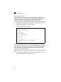
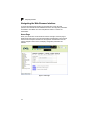
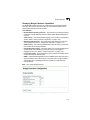
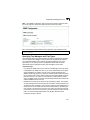
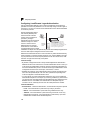
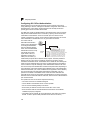
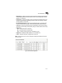
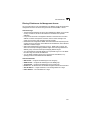
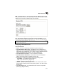
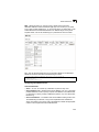
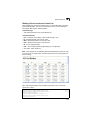
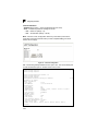
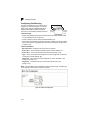
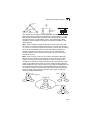
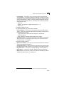
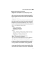
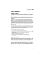
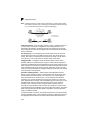
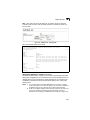
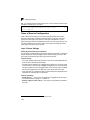
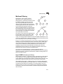
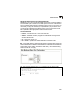
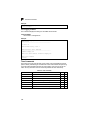
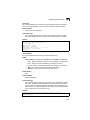
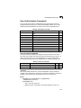
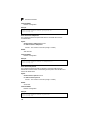
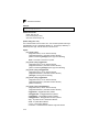
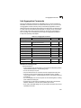
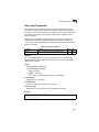
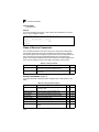
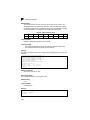
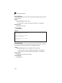
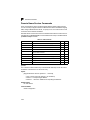
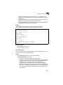
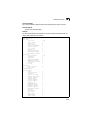
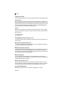
An MST Region consists of a group of interconnected bridges that have the same
MST Configuration Identifiers (including the Region Name, Revision Level and
Configuration Digest – see “Configuring Multiple Spanning Trees” on page 3-136).
An MST Region may contain multiple MSTP Instances. An Internal Spanning Tree
(IST) is used to connect all the MSTP switches within an MST region. A Common
Spanning Tree (CST) interconnects all adjacent MST Regions, and acts as a virtual
bridge node for communications with STP or RSTP nodes in the global network.
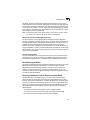
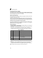
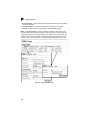
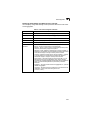
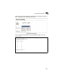
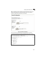
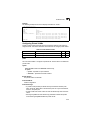
Region 1
Region 1
CIST
CST
IST
Region 2
Region 4
Region 4
Region 3
Region 2
Region 3
MSTP connects all bridges and LAN segments with a single Common and Internal
Spanning Tree (CIST). The CIST is formed as a result of the running spanning tree
algorithm between switches that support the STP, RSTP, MSTP protocols.
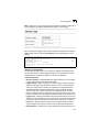
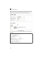
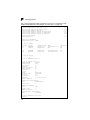
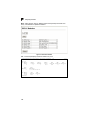
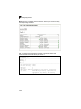
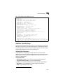
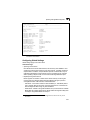
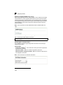
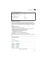
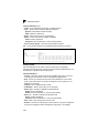
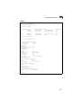
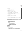
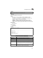
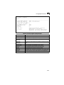
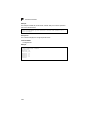
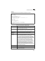
Displaying Global Settings
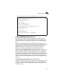
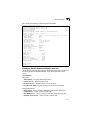
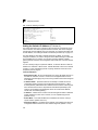
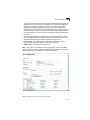
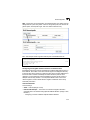
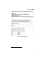
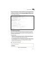
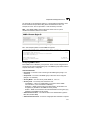
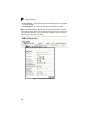
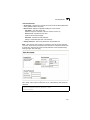
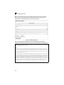
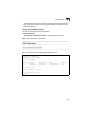
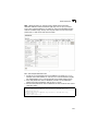
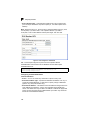
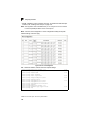
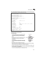
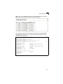
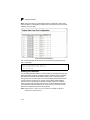
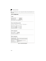
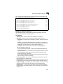
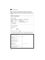
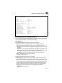
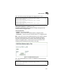
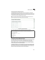
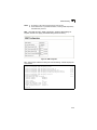
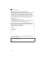
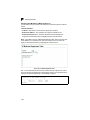
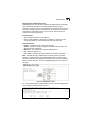
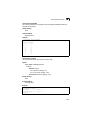
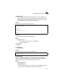
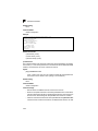
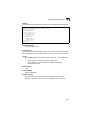
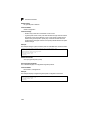
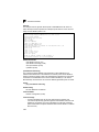
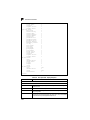
You can display a summary of the current bridge STA information that applies to the
entire switch using the STA Information screen.
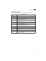
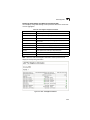
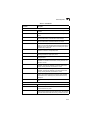
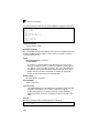
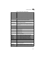
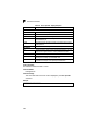
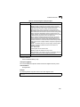
Field Attributes
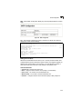
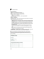
• Spanning Tree State – Shows if the switch is enabled to participate in an
STA-compliant network.
• Bridge ID – A unique identifier for this bridge, consisting of the bridge priority, the
MST Instance ID 0 for the Common Spanning Tree when spanning tree mode is
set to MSTP (page 3-127), and MAC address (where the address is taken from the
switch system).
• Max Age – The maximum time (in seconds) a device can wait without receiving a
configuration message before attempting to reconfigure. All device ports (except
for designated ports) should receive configuration messages at regular intervals.
Any port that ages out STA information (provided in the last configuration
message) becomes the designated port for the attached LAN. If it is a root port, a
new root port is selected from among the device ports attached to the network.
(References to “ports” in this section mean “interfaces,” which includes both ports
and trunks.)
• Hello Time – Interval (in seconds) at which the root device transmits a
configuration message.
• Forward Delay – The maximum time (in seconds) the root device will wait before
changing states (i.e., discarding to learning to forwarding). This delay is required
3-124