1
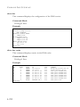
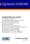
TigerSwitch 10G
Gigabit Ethernet Switch
◆
◆
◆
◆
◆
◆
◆
◆
◆
◆
◆
8 10GBASE XFP slots
Non-blocking switching architecture
Support for a redundant power unit
Spanning Tree Protocol, RSTP, and MSTP
Up to 4 LACP or static 8-port trunks
Layer 2/3/4 CoS support through eight priority queues
Layer 3/4 traffic priority with IP Precedence and IP DSCP
Full support for VLANs with GVRP
IGMP multicast filtering and snooping
Support for jumbo frames up to 9 KB
Manageable via console, Web, SNMP/RMON
Management Guide
SMC8708L2
TigerSwitch 10G
Management Guide
From SMC’s Tiger line of feature-rich workgroup LAN solutions
38 Tesla
Irvine, CA 92618
Phone: (949) 679-8000
May 2005
Pub. # 149100024300A
Information furnished by SMC Networks, Inc. (SMC) is believed to be
accurate and reliable. However, no responsibility is assumed by SMC for its
use, nor for any infringements of patents or other rights of third parties
which may result from its use. No license is granted by implication or otherwise under any patent or patent rights of SMC. SMC reserves the right to
change specifications at any time without notice.
Copyright © 2005 by
SMC Networks, Inc.
38 Tesla
Irvine, CA 92618
All rights reserved. Printed in Taiwan
Trademarks:
SMC is a registered trademark; and EZ Switch, TigerStack and TigerSwitch are trademarks of SMC
Networks, Inc. Other product and company names are trademarks or registered trademarks of their
respective holders.
LIMITED WARRANTY
Limited Warranty Statement: SMC Networks, Inc. (“SMC”) warrants its products to be
free from defects in workmanship and materials, under normal use and service, for the
applicable warranty term. All SMC products carry a standard 90-day limited warranty from
the date of purchase from SMC or its Authorized Reseller. SMC may, at its own discretion,
repair or replace any product not operating as warranted with a similar or functionally
equivalent product, during the applicable warranty term. SMC will endeavor to repair or
replace any product returned under warranty within 30 days of receipt of the product.
The standard limited warranty can be upgraded to a Limited Lifetime* warranty by registering
new products within 30 days of purchase from SMC or its Authorized Reseller. Registration
can be accomplished via the enclosed product registration card or online via the SMC web
site. Failure to register will not affect the standard limited warranty. The Limited Lifetime
warranty covers a product during the Life of that Product, which is defined as the period of
time during which the product is an “Active” SMC product. A product is considered to be
“Active” while it is listed on the current SMC price list. As new technologies emerge, older
technologies become obsolete and SMC will, at its discretion, replace an older product in its
product line with one that incorporates these newer technologies. At that point, the obsolete
product is discontinued and is no longer an “Active” SMC product. A list of discontinued
products with their respective dates of discontinuance can be found at:
http://www.smc.com/index.cfm?action=customer_service_warranty.
All products that are replaced become the property of SMC. Replacement products may be
either new or reconditioned. Any replaced or repaired product carries either a 30-day limited
warranty or the remainder of the initial warranty, whichever is longer. SMC is not responsible
for any custom software or firmware, configuration information, or memory data of
Customer contained in, stored on, or integrated with any products returned to SMC pursuant
to any warranty. Products returned to SMC should have any customer-installed accessory or
add-on components, such as expansion modules, removed prior to returning the product for
replacement. SMC is not responsible for these items if they are returned with the product.
Customers must contact SMC for a Return Material Authorization number prior to returning
any product to SMC. Proof of purchase may be required. Any product returned to SMC
without a valid Return Material Authorization (RMA) number clearly marked on the outside
of the package will be returned to customer at customer’s expense. For warranty claims within
North America, please call our toll-free customer support number at (800) 762-4968.
Customers are responsible for all shipping charges from their facility to SMC. SMC is
responsible for return shipping charges from SMC to customer.
WARRANTIES EXCLUSIVE: IF AN SMC PRODUCT DOES NOT OPERATE AS
WARRANTED ABOVE, CUSTOMER’S SOLE REMEDY SHALL BE REPAIR OR
REPLACEMENT OF THE PRODUCT IN QUESTION, AT SMC’S OPTION. THE
FOREGOING WARRANTIES AND REMEDIES ARE EXCLUSIVE AND ARE IN
LIEU OF ALL OTHER WARRANTIES OR CONDITIONS, EXPRESS OR IMPLIED,
EITHER IN FACT OR BY OPERATION OF LAW, STATUTORY OR OTHERWISE,
INCLUDING WARRANTIES OR CONDITIONS OF MERCHANTABILITY AND
FITNESS FOR A PARTICULAR PURPOSE. SMC NEITHER ASSUMES NOR
AUTHORIZES ANY OTHER PERSON TO ASSUME FOR IT ANY OTHER
v
LIMITED WARRANTY
LIABILITY IN CONNECTION WITH THE SALE, INSTALLATION,
MAINTENANCE OR USE OF ITS PRODUCTS. SMC SHALL NOT BE LIABLE
UNDER THIS WARRANTY IF ITS TESTING AND EXAMINATION DISCLOSE THE
ALLEGED DEFECT IN THE PRODUCT DOES NOT EXIST OR WAS CAUSED BY
CUSTOMER’S OR ANY THIRD PERSON’S MISUSE, NEGLECT, IMPROPER
INSTALLATION OR TESTING, UNAUTHORIZED ATTEMPTS TO REPAIR, OR
ANY OTHER CAUSE BEYOND THE RANGE OF THE INTENDED USE, OR BY
ACCIDENT, FIRE, LIGHTNING, OR OTHER HAZARD.
LIMITATION OF LIABILITY: IN NO EVENT, WHETHER BASED IN CONTRACT
OR TORT (INCLUDING NEGLIGENCE), SHALL SMC BE LIABLE FOR
INCIDENTAL, CONSEQUENTIAL, INDIRECT, SPECIAL, OR PUNITIVE
DAMAGES OF ANY KIND, OR FOR LOSS OF REVENUE, LOSS OF BUSINESS, OR
OTHER FINANCIAL LOSS ARISING OUT OF OR IN CONNECTION WITH THE
SALE, INSTALLATION, MAINTENANCE, USE, PERFORMANCE, FAILURE, OR
INTERRUPTION OF ITS PRODUCTS, EVEN IF SMC OR ITS AUTHORIZED
RESELLER HAS BEEN ADVISED OF THE POSSIBILITY OF SUCH DAMAGES.
SOME STATES DO NOT ALLOW THE EXCLUSION OF IMPLIED WARRANTIES
OR THE LIMITATION OF INCIDENTAL OR CONSEQUENTIAL DAMAGES FOR
CONSUMER PRODUCTS, SO THE ABOVE LIMITATIONS AND EXCLUSIONS
MAY NOT APPLY TO YOU. THIS WARRANTY GIVES YOU SPECIFIC LEGAL
RIGHTS, WHICH MAY VARY FROM STATE TO STATE. NOTHING IN THIS
WARRANTY SHALL BE TAKEN TO AFFECT YOUR STATUTORY RIGHTS.
* SMC will provide warranty service for one year following discontinuance from the active
SMC price list. Under the limited lifetime warranty, internal and external power supplies, fans,
and cables are covered by a standard one-year warranty from date of purchase.
SMC Networks, Inc.
38 Tesla
Irvine, CA 92618
vi
TABLE OF CONTENTS
1
Introduction . . . . . . . . . . . . . . . . . . . . . . . . . . . . . . . . . .1-1
Key Features . . . . . . . . . . . . . . . . . . . . . . . . . . . . . . . . . . . . . . . . . . . . . . . 1-1
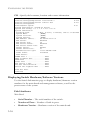
Description of Software Features . . . . . . . . . . . . . . . . . . . . . . . . . . . . . . 1-3
System Defaults . . . . . . . . . . . . . . . . . . . . . . . . . . . . . . . . . . . . . . . . . . . . 1-7
2
Initial Configuration . . . . . . . . . . . . . . . . . . . . . . . . . . 2-1
Connecting to the Switch . . . . . . . . . . . . . . . . . . . . . . . . . . . . . . . . . . . . . 2-1
Configuration Options . . . . . . . . . . . . . . . . . . . . . . . . . . . . . . . . . 2-1
Required Connections . . . . . . . . . . . . . . . . . . . . . . . . . . . . . . . . . 2-2
Remote Connections . . . . . . . . . . . . . . . . . . . . . . . . . . . . . . . . . . 2-4
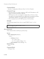
Basic Configuration . . . . . . . . . . . . . . . . . . . . . . . . . . . . . . . . . . . . . . . . . 2-5
Console Connection . . . . . . . . . . . . . . . . . . . . . . . . . . . . . . . . . . . 2-5
Setting Passwords . . . . . . . . . . . . . . . . . . . . . . . . . . . . . . . . . . . . . 2-5
Setting an IP Address . . . . . . . . . . . . . . . . . . . . . . . . . . . . . . . . . . 2-6
Manual Configuration . . . . . . . . . . . . . . . . . . . . . . . . . . . . . . 2-6
Dynamic Configuration . . . . . . . . . . . . . . . . . . . . . . . . . . . . 2-7
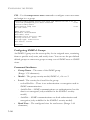
Enabling SNMP Management Access . . . . . . . . . . . . . . . . . . . . . 2-9
Community Strings (for SNMP version 1 and 2c clients) . 2-10
Trap Receivers . . . . . . . . . . . . . . . . . . . . . . . . . . . . . . . . . . . 2-11
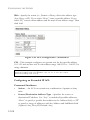
Configuring Access for SNMP Version 3 Clients . . . . . . . 2-11
Saving Configuration Settings . . . . . . . . . . . . . . . . . . . . . . . . . . 2-12
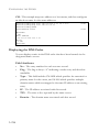
Managing System Files . . . . . . . . . . . . . . . . . . . . . . . . . . . . . . . . . . . . . . 2-13
3
Configuring the Switch . . . . . . . . . . . . . . . . . . . . . . . . 3-1
Using the Web Interface . . . . . . . . . . . . . . . . . . . . . . . . . . . . . . . . . . . . . 3-1
Navigating the Web Browser Interface . . . . . . . . . . . . . . . . . . . . . . . . . . 3-3
Home Page . . . . . . . . . . . . . . . . . . . . . . . . . . . . . . . . . . . . . . . . . . 3-3
Configuration Options . . . . . . . . . . . . . . . . . . . . . . . . . . . . . . . . . 3-4
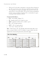
Panel Display . . . . . . . . . . . . . . . . . . . . . . . . . . . . . . . . . . . . . . . . . 3-5
Main Menu . . . . . . . . . . . . . . . . . . . . . . . . . . . . . . . . . . . . . . . . . . 3-6
Basic Configuration . . . . . . . . . . . . . . . . . . . . . . . . . . . . . . . . . . . . . . . . 3-14
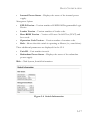
Displaying System Information . . . . . . . . . . . . . . . . . . . . . . . . . 3-14
Displaying Switch Hardware/Software Versions . . . . . . . . . . . 3-16
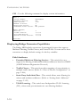
Displaying Bridge Extension Capabilities . . . . . . . . . . . . . . . . . 3-18
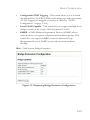
Setting the Switch’s IP Address . . . . . . . . . . . . . . . . . . . . . . . . 3-20
vii
TABLE OF CONTENTS
Manual Configuration . . . . . . . . . . . . . . . . . . . . . . . . . . . . .
Using DHCP/BOOTP . . . . . . . . . . . . . . . . . . . . . . . . . . .
Configuring Support for Jumbo Frames . . . . . . . . . . . . . . . . . .
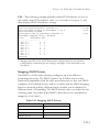
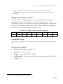
Managing Firmware . . . . . . . . . . . . . . . . . . . . . . . . . . . . . . . . . .
Downloading System Software from a Server . . . . . . . . . .
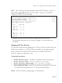
Saving or Restoring Configuration Settings . . . . . . . . . . . . . . .
Downloading Configuration Settings from a Server . . . . .
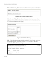
Console Port Settings . . . . . . . . . . . . . . . . . . . . . . . . . . . . . . . . .
Telnet Settings . . . . . . . . . . . . . . . . . . . . . . . . . . . . . . . . . . . . . .
Configuring Event Logging . . . . . . . . . . . . . . . . . . . . . . . . . . . .
System Log Configuration . . . . . . . . . . . . . . . . . . . . . . . . .
Remote Log Configuration . . . . . . . . . . . . . . . . . . . . . . . . .
Displaying Log Messages . . . . . . . . . . . . . . . . . . . . . . . . . .
Sending Simple Mail Transfer Protocol Alerts . . . . . . . . .
Resetting the System . . . . . . . . . . . . . . . . . . . . . . . . . . . . . . . . . .
Setting the System Clock . . . . . . . . . . . . . . . . . . . . . . . . . . . . . .
Configuring SNTP . . . . . . . . . . . . . . . . . . . . . . . . . . . . . . .
Setting the Time Zone . . . . . . . . . . . . . . . . . . . . . . . . . . . .
Simple Network Management Protocol . . . . . . . . . . . . . . . . . . . . . . . .
Enabling the SNMP Agent . . . . . . . . . . . . . . . . . . . . . . . . . . . .
Setting Community Access Strings . . . . . . . . . . . . . . . . . . . . . .
Specifying Trap Managers and Trap Types . . . . . . . . . . . . . . . .
Configuring SNMPv3 Management Access . . . . . . . . . . . . . . .
Setting a Local Engine ID . . . . . . . . . . . . . . . . . . . . . . . . .
Specifying a Remote Engine ID . . . . . . . . . . . . . . . . . . . . .
Configuring SNMPv3 Users . . . . . . . . . . . . . . . . . . . . . . . .
Configuring Remote SNMPv3 Users . . . . . . . . . . . . . . . . .
Configuring SNMPv3 Groups . . . . . . . . . . . . . . . . . . . . . .
Setting SNMPv3 Views . . . . . . . . . . . . . . . . . . . . . . . . . . . .
User Authentication . . . . . . . . . . . . . . . . . . . . . . . . . . . . . . . . . . . . . . . .
Configuring User Accounts . . . . . . . . . . . . . . . . . . . . . . . . . . .
Configuring Local/Remote Logon Authentication . . . . . . . . .
Configuring HTTPS . . . . . . . . . . . . . . . . . . . . . . . . . . . . . . . . . .
Replacing the Default Secure-site Certificate . . . . . . . . . .
Configuring the Secure Shell . . . . . . . . . . . . . . . . . . . . . . . . . . .
Generating the Host Key Pair . . . . . . . . . . . . . . . . . . . . . .
Configuring the SSH Server . . . . . . . . . . . . . . . . . . . . . . . .
viii
3-22
3-22
3-24
3-25
3-27
3-30
3-32
3-33
3-36
3-38
3-38
3-40
3-43
3-44
3-46
3-47
3-47
3-49
3-50
3-53
3-53
3-55
3-58
3-59
3-60
3-61
3-63
3-66
3-72
3-74
3-75
3-76
3-81
3-83
3-84
3-87
3-89
TABLE OF CONTENTS
Configuring Port Security . . . . . . . . . . . . . . . . . . . . . . . . . . . . . . 3-91
Configuring 802.1X Port Authentication . . . . . . . . . . . . . . . . . 3-94
Displaying 802.1X Global Settings . . . . . . . . . . . . . . . . . . . 3-95
Configuring 802.1X Global Settings . . . . . . . . . . . . . . . . . 3-96
Configuring Port Settings for 802.1X . . . . . . . . . . . . . . . . 3-97
Displaying 802.1X Statistics . . . . . . . . . . . . . . . . . . . . . . . 3-101
Filtering IP Addresses for Management Access . . . . . . . . . . . 3-103
Access Control Lists . . . . . . . . . . . . . . . . . . . . . . . . . . . . . . . . . . . . . . . 3-105
Configuring Access Control Lists . . . . . . . . . . . . . . . . . . . . . . 3-105
Setting the ACL Name and Type . . . . . . . . . . . . . . . . . . . 3-106
Configuring a Standard IP ACL . . . . . . . . . . . . . . . . . . . . 3-107
Configuring an Extended IP ACL . . . . . . . . . . . . . . . . . . 3-108
Configuring a MAC ACL . . . . . . . . . . . . . . . . . . . . . . . . . 3-111
Configuring ACL Masks . . . . . . . . . . . . . . . . . . . . . . . . . . . . . . 3-113
Specifying the Mask Type . . . . . . . . . . . . . . . . . . . . . . . . . 3-113
Configuring an IP ACL Mask . . . . . . . . . . . . . . . . . . . . . . 3-114
Configuring a MAC ACL Mask . . . . . . . . . . . . . . . . . . . . 3-117
Binding a Port to an Access Control List . . . . . . . . . . . . . . . . 3-119
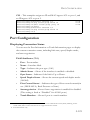
Port Configuration . . . . . . . . . . . . . . . . . . . . . . . . . . . . . . . . . . . . . . . . 3-121
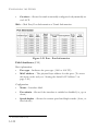
Displaying Connection Status . . . . . . . . . . . . . . . . . . . . . . . . . 3-121
Configuring Interface Connections . . . . . . . . . . . . . . . . . . . . . 3-125
Creating Trunk Groups . . . . . . . . . . . . . . . . . . . . . . . . . . . . . . 3-127
Statically Configuring a Trunk . . . . . . . . . . . . . . . . . . . . . 3-128
Enabling LACP on Selected Ports . . . . . . . . . . . . . . . . . . 3-130
Configuring LACP Parameters . . . . . . . . . . . . . . . . . . . . . 3-132
Displaying LACP Port Counters . . . . . . . . . . . . . . . . . . . 3-135
Displaying LACP Settings and Status for the Local Side 3-136
Displaying LACP Settings and Status for the Remote Side 3-139
Setting Broadcast Storm Thresholds . . . . . . . . . . . . . . . . . . . . 3-141
Configuring Port Mirroring . . . . . . . . . . . . . . . . . . . . . . . . . . . 3-143
Configuring Rate Limits . . . . . . . . . . . . . . . . . . . . . . . . . . . . . . 3-145
Showing Port Statistics . . . . . . . . . . . . . . . . . . . . . . . . . . . . . . . 3-146
Address Table Settings . . . . . . . . . . . . . . . . . . . . . . . . . . . . . . . . . . . . . 3-152
Setting Static Addresses . . . . . . . . . . . . . . . . . . . . . . . . . . . . . . 3-153
Displaying the Address Table . . . . . . . . . . . . . . . . . . . . . . . . . . 3-154
Changing the Aging Time . . . . . . . . . . . . . . . . . . . . . . . . . . . . . 3-156
ix
TABLE OF CONTENTS
Spanning Tree Algorithm Configuration . . . . . . . . . . . . . . . . . . . . . .
Displaying Global Settings . . . . . . . . . . . . . . . . . . . . . . . . . . . .
Configuring Global Settings . . . . . . . . . . . . . . . . . . . . . . . . . . .
Displaying Interface Settings . . . . . . . . . . . . . . . . . . . . . . . . . .
Configuring Interface Settings . . . . . . . . . . . . . . . . . . . . . . . . .
Configuring Multiple Spanning Trees . . . . . . . . . . . . . . . . . . .
Displaying Interface Settings for MSTP . . . . . . . . . . . . . . . . .
Configuring Interface Settings for MSTP . . . . . . . . . . . . . . . .
VLAN Configuration . . . . . . . . . . . . . . . . . . . . . . . . . . . . . . . . . . . . . .
IEEE 802.1Q VLANs . . . . . . . . . . . . . . . . . . . . . . . . . . . . . . .
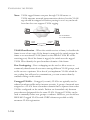
Assigning Ports to VLANs . . . . . . . . . . . . . . . . . . . . . . . .
Forwarding Tagged/Untagged Frames . . . . . . . . . . . . . .
Enabling or Disabling GVRP (Global Setting) . . . . . . . . . . .
Displaying Basic VLAN Information . . . . . . . . . . . . . . . . . . .
Displaying Current VLANs . . . . . . . . . . . . . . . . . . . . . . . . . . .
Creating VLANs . . . . . . . . . . . . . . . . . . . . . . . . . . . . . . . . . . . .
Adding Static Members to VLANs (VLAN Index) . . . . . . . .
Adding Static Members to VLANs (Port Index) . . . . . . . . . .
Configuring VLAN Behavior for Interfaces . . . . . . . . . . . . . .
Configuring Private VLANs . . . . . . . . . . . . . . . . . . . . . . . . . .
Enabling Private VLANs . . . . . . . . . . . . . . . . . . . . . . . . .
Configuring Uplink and Downlink Ports . . . . . . . . . . . .
Configuring Protocol-Based VLANs . . . . . . . . . . . . . . . . . . .
Configuring Protocol Groups . . . . . . . . . . . . . . . . . . . . .
Mapping Protocols to VLANs . . . . . . . . . . . . . . . . . . . . .
Class of Service Configuration . . . . . . . . . . . . . . . . . . . . . . . . . . . . . .
Layer 2 Queue Settings . . . . . . . . . . . . . . . . . . . . . . . . . . . . . . .
Setting the Default Priority for Interfaces . . . . . . . . . . . .
Mapping CoS Values to Egress Queues . . . . . . . . . . . . .
Selecting the Queue Mode . . . . . . . . . . . . . . . . . . . . . . . .
Setting the Service Weight for Traffic Classes . . . . . . . . .
Layer 3/4 Priority Settings . . . . . . . . . . . . . . . . . . . . . . . . . . . .
Mapping Layer 3/4 Priorities to CoS Values . . . . . . . . . .
Selecting IP Precedence/DSCP Priority . . . . . . . . . . . . .
Mapping IP Precedence . . . . . . . . . . . . . . . . . . . . . . . . . .
Mapping DSCP Priority . . . . . . . . . . . . . . . . . . . . . . . . . .
Mapping IP Port Priority . . . . . . . . . . . . . . . . . . . . . . . . .
x
3-156
3-158
3-163
3-168
3-172
3-176
3-180
3-182
3-184
3-184
3-185
3-188
3-189
3-189
3-190
3-192
3-194
3-196
3-197
3-200
3-200
3-201
3-202
3-203
3-204
3-206
3-206
3-206
3-208
3-209
3-210
3-212
3-212
3-213
3-213
3-215
3-217
TABLE OF CONTENTS
Mapping CoS Values to ACLs . . . . . . . . . . . . . . . . . . . . . 3-219
Multicast Filtering . . . . . . . . . . . . . . . . . . . . . . . . . . . . . . . . . . . . . . . . 3-221
IGMP Protocol . . . . . . . . . . . . . . . . . . . . . . . . . . . . . . . . . . . . . 3-222
Layer 2 IGMP (Snooping and Query) . . . . . . . . . . . . . . . . . . . 3-222
Configuring IGMP Snooping and Query Parameters . . . 3-223
Displaying Interfaces Attached to a Multicast Router . . . 3-226
Specifying Static Interfaces for a Multicast Router . . . . . 3-227
Displaying Port Members of Multicast Services . . . . . . . 3-228
Assigning Ports to Multicast Services . . . . . . . . . . . . . . . 3-229
Configuring Domain Name Service . . . . . . . . . . . . . . . . . . . . . . . . . . 3-231
Configuring General DNS Service Parameters . . . . . . . . . . . 3-231
Configuring Static DNS Host to Address Entries . . . . . . . . . 3-234
Displaying the DNS Cache . . . . . . . . . . . . . . . . . . . . . . . . . . . 3-236
4
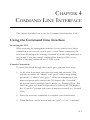
Command Line Interface . . . . . . . . . . . . . . . . . . . . . . 4-1
Using the Command Line Interface . . . . . . . . . . . . . . . . . . . . . . . . . . . . 4-1
Accessing the CLI . . . . . . . . . . . . . . . . . . . . . . . . . . . . . . . . . . . . . 4-1
Console Connection . . . . . . . . . . . . . . . . . . . . . . . . . . . . . . . . . . . 4-1
Telnet Connection . . . . . . . . . . . . . . . . . . . . . . . . . . . . . . . . . . . . 4-2
Entering Commands . . . . . . . . . . . . . . . . . . . . . . . . . . . . . . . . . . . . . . . . 4-4
Keywords and Arguments . . . . . . . . . . . . . . . . . . . . . . . . . . . . . . 4-4
Minimum Abbreviation . . . . . . . . . . . . . . . . . . . . . . . . . . . . . . . . 4-4
Command Completion . . . . . . . . . . . . . . . . . . . . . . . . . . . . . . . . . 4-5
Getting Help on Commands . . . . . . . . . . . . . . . . . . . . . . . . . . . . 4-5
Showing Commands . . . . . . . . . . . . . . . . . . . . . . . . . . . . . . . 4-6
Partial Keyword Lookup . . . . . . . . . . . . . . . . . . . . . . . . . . . . . . . 4-7
Negating the Effect of Commands . . . . . . . . . . . . . . . . . . . . . . . 4-7
Using Command History . . . . . . . . . . . . . . . . . . . . . . . . . . . . . . . 4-7
Understanding Command Modes . . . . . . . . . . . . . . . . . . . . . . . . 4-8
Exec Commands . . . . . . . . . . . . . . . . . . . . . . . . . . . . . . . . . . . . . . 4-8
Configuration Commands . . . . . . . . . . . . . . . . . . . . . . . . . . . . . . 4-9
Command Line Processing . . . . . . . . . . . . . . . . . . . . . . . . . . . . 4-11
Command Groups . . . . . . . . . . . . . . . . . . . . . . . . . . . . . . . . . . . . . . . . . 4-12
Line Commands . . . . . . . . . . . . . . . . . . . . . . . . . . . . . . . . . . . . . . . . . . . 4-14
line . . . . . . . . . . . . . . . . . . . . . . . . . . . . . . . . . . . . . . . . . . . . . . . . 4-15
login . . . . . . . . . . . . . . . . . . . . . . . . . . . . . . . . . . . . . . . . . . . . . . . 4-16
password . . . . . . . . . . . . . . . . . . . . . . . . . . . . . . . . . . . . . . . . . . . 4-17
xi
TABLE OF CONTENTS
timeout login response . . . . . . . . . . . . . . . . . . . . . . . . . . . . . . . .
exec-timeout . . . . . . . . . . . . . . . . . . . . . . . . . . . . . . . . . . . . . . . .
password-thresh . . . . . . . . . . . . . . . . . . . . . . . . . . . . . . . . . . . . .
silent-time . . . . . . . . . . . . . . . . . . . . . . . . . . . . . . . . . . . . . . . . . .
databits . . . . . . . . . . . . . . . . . . . . . . . . . . . . . . . . . . . . . . . . . . . .
parity . . . . . . . . . . . . . . . . . . . . . . . . . . . . . . . . . . . . . . . . . . . . . .
speed . . . . . . . . . . . . . . . . . . . . . . . . . . . . . . . . . . . . . . . . . . . . . .
stopbits . . . . . . . . . . . . . . . . . . . . . . . . . . . . . . . . . . . . . . . . . . . .
disconnect . . . . . . . . . . . . . . . . . . . . . . . . . . . . . . . . . . . . . . . . . .
show line . . . . . . . . . . . . . . . . . . . . . . . . . . . . . . . . . . . . . . . . . . .
General Commands . . . . . . . . . . . . . . . . . . . . . . . . . . . . . . . . . . . . . . . .
enable . . . . . . . . . . . . . . . . . . . . . . . . . . . . . . . . . . . . . . . . . . . . .
disable . . . . . . . . . . . . . . . . . . . . . . . . . . . . . . . . . . . . . . . . . . . . .
configure . . . . . . . . . . . . . . . . . . . . . . . . . . . . . . . . . . . . . . . . . . .
show history . . . . . . . . . . . . . . . . . . . . . . . . . . . . . . . . . . . . . . . .
reload . . . . . . . . . . . . . . . . . . . . . . . . . . . . . . . . . . . . . . . . . . . . . .
end . . . . . . . . . . . . . . . . . . . . . . . . . . . . . . . . . . . . . . . . . . . . . . . .
exit . . . . . . . . . . . . . . . . . . . . . . . . . . . . . . . . . . . . . . . . . . . . . . . .
quit . . . . . . . . . . . . . . . . . . . . . . . . . . . . . . . . . . . . . . . . . . . . . . . .
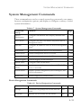
System Management Commands . . . . . . . . . . . . . . . . . . . . . . . . . . . . .
Device Designation Commands . . . . . . . . . . . . . . . . . . . . . . . .
prompt . . . . . . . . . . . . . . . . . . . . . . . . . . . . . . . . . . . . . . . . .
hostname . . . . . . . . . . . . . . . . . . . . . . . . . . . . . . . . . . . . . . .
User Access Commands . . . . . . . . . . . . . . . . . . . . . . . . . . . . . . .
username . . . . . . . . . . . . . . . . . . . . . . . . . . . . . . . . . . . . . . .
enable password . . . . . . . . . . . . . . . . . . . . . . . . . . . . . . . . .
IP Filter Commands . . . . . . . . . . . . . . . . . . . . . . . . . . . . . . . . . .
management . . . . . . . . . . . . . . . . . . . . . . . . . . . . . . . . . . . .
show management . . . . . . . . . . . . . . . . . . . . . . . . . . . . . . .
Web Server Commands . . . . . . . . . . . . . . . . . . . . . . . . . . . . . . .
ip http port . . . . . . . . . . . . . . . . . . . . . . . . . . . . . . . . . . . . .
ip http server . . . . . . . . . . . . . . . . . . . . . . . . . . . . . . . . . . . .
ip http secure-server . . . . . . . . . . . . . . . . . . . . . . . . . . . . . .
ip http secure-port . . . . . . . . . . . . . . . . . . . . . . . . . . . . . . .
Telnet Server Commands . . . . . . . . . . . . . . . . . . . . . . . . . . . . . .
ip telnet server . . . . . . . . . . . . . . . . . . . . . . . . . . . . . . . . . . .
xii
4-18
4-19
4-20
4-21
4-22
4-23
4-23
4-24
4-25
4-25
4-26
4-27
4-28
4-29
4-29
4-30
4-31
4-31
4-32
4-33
4-33
4-34
4-34
4-35
4-36
4-37
4-38
4-39
4-40
4-41
4-42
4-42
4-43
4-44
4-45
4-46
TABLE OF CONTENTS
Secure Shell Commands . . . . . . . . . . . . . . . . . . . . . . . . . . . . . . . 4-46
ip ssh server . . . . . . . . . . . . . . . . . . . . . . . . . . . . . . . . . . . . . 4-50
ip ssh timeout . . . . . . . . . . . . . . . . . . . . . . . . . . . . . . . . . . . 4-51
ip ssh authentication-retries . . . . . . . . . . . . . . . . . . . . . . . . 4-52
ip ssh server-key size . . . . . . . . . . . . . . . . . . . . . . . . . . . . . . 4-52
delete public-key . . . . . . . . . . . . . . . . . . . . . . . . . . . . . . . . . 4-53
ip ssh crypto host-key generate . . . . . . . . . . . . . . . . . . . . . 4-53
ip ssh crypto zeroize . . . . . . . . . . . . . . . . . . . . . . . . . . . . . . 4-54
ip ssh save host-key . . . . . . . . . . . . . . . . . . . . . . . . . . . . . . . 4-55
show ip ssh . . . . . . . . . . . . . . . . . . . . . . . . . . . . . . . . . . . . . 4-56
show ssh . . . . . . . . . . . . . . . . . . . . . . . . . . . . . . . . . . . . . . . 4-56
show public-key . . . . . . . . . . . . . . . . . . . . . . . . . . . . . . . . . . 4-57
Event Logging Commands . . . . . . . . . . . . . . . . . . . . . . . . . . . . 4-59
logging on . . . . . . . . . . . . . . . . . . . . . . . . . . . . . . . . . . . . . . 4-59
logging history . . . . . . . . . . . . . . . . . . . . . . . . . . . . . . . . . . . 4-60
logging host . . . . . . . . . . . . . . . . . . . . . . . . . . . . . . . . . . . . . 4-61
logging facility . . . . . . . . . . . . . . . . . . . . . . . . . . . . . . . . . . . 4-62
logging trap . . . . . . . . . . . . . . . . . . . . . . . . . . . . . . . . . . . . . 4-63
clear log . . . . . . . . . . . . . . . . . . . . . . . . . . . . . . . . . . . . . . . . 4-64
show logging . . . . . . . . . . . . . . . . . . . . . . . . . . . . . . . . . . . . 4-64
show log . . . . . . . . . . . . . . . . . . . . . . . . . . . . . . . . . . . . . . . . 4-66
SMTP Alert Commands . . . . . . . . . . . . . . . . . . . . . . . . . . . . . . . 4-67
logging sendmail host . . . . . . . . . . . . . . . . . . . . . . . . . . . . . 4-68
logging sendmail level . . . . . . . . . . . . . . . . . . . . . . . . . . . . . 4-69
logging sendmail source-email . . . . . . . . . . . . . . . . . . . . . . 4-69
logging sendmail destination-email . . . . . . . . . . . . . . . . . . 4-70
logging sendmail . . . . . . . . . . . . . . . . . . . . . . . . . . . . . . . . . 4-71
show logging sendmail . . . . . . . . . . . . . . . . . . . . . . . . . . . . 4-71
Time Commands . . . . . . . . . . . . . . . . . . . . . . . . . . . . . . . . . . . . 4-72
sntp client . . . . . . . . . . . . . . . . . . . . . . . . . . . . . . . . . . . . . . 4-72
sntp server . . . . . . . . . . . . . . . . . . . . . . . . . . . . . . . . . . . . . . 4-73
sntp poll . . . . . . . . . . . . . . . . . . . . . . . . . . . . . . . . . . . . . . . . 4-74
show sntp . . . . . . . . . . . . . . . . . . . . . . . . . . . . . . . . . . . . . . . 4-75
clock timezone . . . . . . . . . . . . . . . . . . . . . . . . . . . . . . . . . . . 4-76
calendar set . . . . . . . . . . . . . . . . . . . . . . . . . . . . . . . . . . . . . 4-77
show calendar . . . . . . . . . . . . . . . . . . . . . . . . . . . . . . . . . . . 4-77
xiii
TABLE OF CONTENTS
System Status Commands . . . . . . . . . . . . . . . . . . . . . . . . . . . . . 4-78
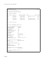
show startup-config . . . . . . . . . . . . . . . . . . . . . . . . . . . . . . 4-78
show running-config . . . . . . . . . . . . . . . . . . . . . . . . . . . . . . 4-81
show system . . . . . . . . . . . . . . . . . . . . . . . . . . . . . . . . . . . . 4-83
show users . . . . . . . . . . . . . . . . . . . . . . . . . . . . . . . . . . . . . . 4-84
show version . . . . . . . . . . . . . . . . . . . . . . . . . . . . . . . . . . . . 4-84
Frame Size Commands . . . . . . . . . . . . . . . . . . . . . . . . . . . . . . . . 4-85
jumbo frame . . . . . . . . . . . . . . . . . . . . . . . . . . . . . . . . . . . . 4-85
Flash/File Commands . . . . . . . . . . . . . . . . . . . . . . . . . . . . . . . . . . . . . . 4-86
copy . . . . . . . . . . . . . . . . . . . . . . . . . . . . . . . . . . . . . . . . . . . . . 4-87
delete . . . . . . . . . . . . . . . . . . . . . . . . . . . . . . . . . . . . . . . . . . . . . . 4-90
dir . . . . . . . . . . . . . . . . . . . . . . . . . . . . . . . . . . . . . . . . . . . . . . . . . 4-91
whichboot . . . . . . . . . . . . . . . . . . . . . . . . . . . . . . . . . . . . . . . . . . 4-92
boot system . . . . . . . . . . . . . . . . . . . . . . . . . . . . . . . . . . . . . . . . . 4-93
Authentication Commands . . . . . . . . . . . . . . . . . . . . . . . . . . . . . . . . . . 4-94
Authentication Sequence . . . . . . . . . . . . . . . . . . . . . . . . . . . . . . 4-94
authentication login . . . . . . . . . . . . . . . . . . . . . . . . . . . . . . . 4-95
authentication enable . . . . . . . . . . . . . . . . . . . . . . . . . . . . . 4-96
RADIUS Client . . . . . . . . . . . . . . . . . . . . . . . . . . . . . . . . . . . . . . 4-97
radius-server host . . . . . . . . . . . . . . . . . . . . . . . . . . . . . . . . 4-98
radius-server port . . . . . . . . . . . . . . . . . . . . . . . . . . . . . . . . 4-99
radius-server key . . . . . . . . . . . . . . . . . . . . . . . . . . . . . . . . . 4-99
radius-server retransmit . . . . . . . . . . . . . . . . . . . . . . . . . . 4-100
radius-server timeout . . . . . . . . . . . . . . . . . . . . . . . . . . . . 4-100
show radius-server . . . . . . . . . . . . . . . . . . . . . . . . . . . . . . 4-101
TACACS+ Client . . . . . . . . . . . . . . . . . . . . . . . . . . . . . . . . . . . 4-102
tacacs-server host . . . . . . . . . . . . . . . . . . . . . . . . . . . . . . . 4-102
tacacs-server port . . . . . . . . . . . . . . . . . . . . . . . . . . . . . . . 4-103
tacacs-server key . . . . . . . . . . . . . . . . . . . . . . . . . . . . . . . . 4-103
show tacacs-server . . . . . . . . . . . . . . . . . . . . . . . . . . . . . . 4-104
Port Security Commands . . . . . . . . . . . . . . . . . . . . . . . . . . . . . 4-104
port security . . . . . . . . . . . . . . . . . . . . . . . . . . . . . . . . . . . . 4-105
802.1X Port Authentication . . . . . . . . . . . . . . . . . . . . . . . . . . . 4-107
dot1x system-auth-control . . . . . . . . . . . . . . . . . . . . . . . . 4-108
dot1x default . . . . . . . . . . . . . . . . . . . . . . . . . . . . . . . . . . . 4-108
dot1x max-req . . . . . . . . . . . . . . . . . . . . . . . . . . . . . . . . . . 4-108
dot1x port-control . . . . . . . . . . . . . . . . . . . . . . . . . . . . . . 4-109
xiv
TABLE OF CONTENTS
dot1x operation-mode . . . . . . . . . . . . . . . . . . . . . . . . . . . 4-110
dot1x re-authenticate . . . . . . . . . . . . . . . . . . . . . . . . . . . . 4-111
dot1x re-authentication . . . . . . . . . . . . . . . . . . . . . . . . . . . 4-111
dot1x timeout quiet-period . . . . . . . . . . . . . . . . . . . . . . . . 4-112
dot1x timeout re-authperiod . . . . . . . . . . . . . . . . . . . . . . . 4-112
dot1x timeout tx-period . . . . . . . . . . . . . . . . . . . . . . . . . . 4-113
show dot1x . . . . . . . . . . . . . . . . . . . . . . . . . . . . . . . . . . . . 4-113
Access Control List Commands . . . . . . . . . . . . . . . . . . . . . . . . . . . . . 4-117
IP ACLs . . . . . . . . . . . . . . . . . . . . . . . . . . . . . . . . . . . . . . . . . . 4-119
access-list ip . . . . . . . . . . . . . . . . . . . . . . . . . . . . . . . . . . . . 4-120
access-list ip extended fragment-auto-mask . . . . . . . . . . . 4-121
permit, deny (Standard ACL) . . . . . . . . . . . . . . . . . . . . . 4-122
permit, deny (Extended ACL) . . . . . . . . . . . . . . . . . . . . . 4-123
show ip access-list . . . . . . . . . . . . . . . . . . . . . . . . . . . . . . . 4-126
access-list ip mask-precedence . . . . . . . . . . . . . . . . . . . . . 4-126
mask (IP ACL) . . . . . . . . . . . . . . . . . . . . . . . . . . . . . . . . . 4-128
show access-list ip mask-precedence . . . . . . . . . . . . . . . . 4-131
ip access-group . . . . . . . . . . . . . . . . . . . . . . . . . . . . . . . . . 4-132
show ip access-group . . . . . . . . . . . . . . . . . . . . . . . . . . . . 4-133
map access-list ip . . . . . . . . . . . . . . . . . . . . . . . . . . . . . . . . 4-133
show map access-list ip . . . . . . . . . . . . . . . . . . . . . . . . . . . 4-134
match access-list ip . . . . . . . . . . . . . . . . . . . . . . . . . . . . . . 4-135
show marking . . . . . . . . . . . . . . . . . . . . . . . . . . . . . . . . . . 4-136
MAC ACLs . . . . . . . . . . . . . . . . . . . . . . . . . . . . . . . . . . . . . . . 4-137
access-list mac . . . . . . . . . . . . . . . . . . . . . . . . . . . . . . . . . 4-138
permit, deny (MAC ACL) . . . . . . . . . . . . . . . . . . . . . . . . . 4-139
show mac access-list . . . . . . . . . . . . . . . . . . . . . . . . . . . . 4-141
access-list mac mask-precedence . . . . . . . . . . . . . . . . . . . 4-141
mask (MAC ACL) . . . . . . . . . . . . . . . . . . . . . . . . . . . . . . . 4-142
show access-list mac mask-precedence . . . . . . . . . . . . . . 4-144
mac access-group . . . . . . . . . . . . . . . . . . . . . . . . . . . . . . . 4-145
show mac access-group . . . . . . . . . . . . . . . . . . . . . . . . . . . 4-145
map access-list mac . . . . . . . . . . . . . . . . . . . . . . . . . . . . . . 4-146
show map access-list mac . . . . . . . . . . . . . . . . . . . . . . . . . 4-147
match access-list mac . . . . . . . . . . . . . . . . . . . . . . . . . . . . 4-148
ACL Information . . . . . . . . . . . . . . . . . . . . . . . . . . . . . . . . . . . 4-149
show access-list . . . . . . . . . . . . . . . . . . . . . . . . . . . . . . . . . 4-149
xv
TABLE OF CONTENTS
show access-group . . . . . . . . . . . . . . . . . . . . . . . . . . . . . .
SNMP Commands . . . . . . . . . . . . . . . . . . . . . . . . . . . . . . . . . . . . . . . .
snmp-server . . . . . . . . . . . . . . . . . . . . . . . . . . . . . . . . . . . . . . . .
show snmp . . . . . . . . . . . . . . . . . . . . . . . . . . . . . . . . . . . . . . . .
snmp-server community . . . . . . . . . . . . . . . . . . . . . . . . . . . . . .
snmp-server contact . . . . . . . . . . . . . . . . . . . . . . . . . . . . . . . . .
snmp-server location . . . . . . . . . . . . . . . . . . . . . . . . . . . . . . . .
snmp-server host . . . . . . . . . . . . . . . . . . . . . . . . . . . . . . . . . . .
snmp-server enable traps . . . . . . . . . . . . . . . . . . . . . . . . . . . . .
snmp-server engine-id . . . . . . . . . . . . . . . . . . . . . . . . . . . . . . .
show snmp engine-id . . . . . . . . . . . . . . . . . . . . . . . . . . . . . . . .
snmp-server view . . . . . . . . . . . . . . . . . . . . . . . . . . . . . . . . . . .
show snmp view . . . . . . . . . . . . . . . . . . . . . . . . . . . . . . . . . . . .
snmp-server group . . . . . . . . . . . . . . . . . . . . . . . . . . . . . . . . . .
show snmp group . . . . . . . . . . . . . . . . . . . . . . . . . . . . . . . . . . .
snmp-server user . . . . . . . . . . . . . . . . . . . . . . . . . . . . . . . . . . . .
show snmp user . . . . . . . . . . . . . . . . . . . . . . . . . . . . . . . . . . . .
Interface Commands . . . . . . . . . . . . . . . . . . . . . . . . . . . . . . . . . . . . . .
interface . . . . . . . . . . . . . . . . . . . . . . . . . . . . . . . . . . . . . . . . . . .
description . . . . . . . . . . . . . . . . . . . . . . . . . . . . . . . . . . . . . . . . .
speed-duplex . . . . . . . . . . . . . . . . . . . . . . . . . . . . . . . . . . . . . . .
negotiation . . . . . . . . . . . . . . . . . . . . . . . . . . . . . . . . . . . . . . . .
capabilities . . . . . . . . . . . . . . . . . . . . . . . . . . . . . . . . . . . . . . . . .
shutdown . . . . . . . . . . . . . . . . . . . . . . . . . . . . . . . . . . . . . . . . . .
switchport broadcast packet-rate . . . . . . . . . . . . . . . . . . . . . . .
clear counters . . . . . . . . . . . . . . . . . . . . . . . . . . . . . . . . . . . . . .
show interfaces status . . . . . . . . . . . . . . . . . . . . . . . . . . . . . . . .
show interfaces counters . . . . . . . . . . . . . . . . . . . . . . . . . . . . .
show interfaces switchport . . . . . . . . . . . . . . . . . . . . . . . . . . . .
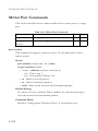
Mirror Port Commands . . . . . . . . . . . . . . . . . . . . . . . . . . . . . . . . . . . .
port monitor . . . . . . . . . . . . . . . . . . . . . . . . . . . . . . . . . . . . . . .
show port monitor . . . . . . . . . . . . . . . . . . . . . . . . . . . . . . . . . .
Rate Limit Commands . . . . . . . . . . . . . . . . . . . . . . . . . . . . . . . . . . . . .
rate-limit . . . . . . . . . . . . . . . . . . . . . . . . . . . . . . . . . . . . . . . . . .
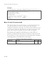
Link Aggregation Commands . . . . . . . . . . . . . . . . . . . . . . . . . . . . . . .
channel-group . . . . . . . . . . . . . . . . . . . . . . . . . . . . . . . . . . . . .
lacp . . . . . . . . . . . . . . . . . . . . . . . . . . . . . . . . . . . . . . . . . . . . . .
xvi
4-149
4-150
4-151
4-152
4-153
4-153
4-154
4-155
4-158
4-159
4-160
4-161
4-162
4-163
4-164
4-166
4-168
4-169
4-170
4-170
4-171
4-172
4-173
4-174
4-175
4-176
4-177
4-178
4-180
4-182
4-182
4-183
4-184
4-185
4-185
4-187
4-188
TABLE OF CONTENTS
lacp system-priority . . . . . . . . . . . . . . . . . . . . . . . . . . . . . . . . . . 4-190
lacp admin-key (Ethernet Interface) . . . . . . . . . . . . . . . . . . . . 4-191
lacp admin-key (Port Channel) . . . . . . . . . . . . . . . . . . . . . . . . . 4-192
lacp port-priority . . . . . . . . . . . . . . . . . . . . . . . . . . . . . . . . . . . . 4-193
show lacp . . . . . . . . . . . . . . . . . . . . . . . . . . . . . . . . . . . . . . . . . . 4-194
Address Table Commands . . . . . . . . . . . . . . . . . . . . . . . . . . . . . . . . . . 4-198
mac-address-table static . . . . . . . . . . . . . . . . . . . . . . . . . . . . . . 4-199
clear mac-address-table dynamic . . . . . . . . . . . . . . . . . . . . . . . 4-200
show mac-address-table . . . . . . . . . . . . . . . . . . . . . . . . . . . . . . 4-201
mac-address-table aging-time . . . . . . . . . . . . . . . . . . . . . . . . . . 4-202
show mac-address-table aging-time . . . . . . . . . . . . . . . . . . . . . 4-203
Spanning Tree Commands . . . . . . . . . . . . . . . . . . . . . . . . . . . . . . . . . . 4-204
spanning-tree . . . . . . . . . . . . . . . . . . . . . . . . . . . . . . . . . . . . . . . 4-205
spanning-tree mode . . . . . . . . . . . . . . . . . . . . . . . . . . . . . . . . . 4-206
spanning-tree forward-time . . . . . . . . . . . . . . . . . . . . . . . . . . . 4-208
spanning-tree hello-time . . . . . . . . . . . . . . . . . . . . . . . . . . . . . . 4-209
spanning-tree max-age . . . . . . . . . . . . . . . . . . . . . . . . . . . . . . . 4-209
spanning-tree priority . . . . . . . . . . . . . . . . . . . . . . . . . . . . . . . . 4-210
spanning-tree pathcost method . . . . . . . . . . . . . . . . . . . . . . . . 4-211
spanning-tree transmission-limit . . . . . . . . . . . . . . . . . . . . . . . 4-212
spanning-tree mst-configuration . . . . . . . . . . . . . . . . . . . . . . . 4-212
mst vlan . . . . . . . . . . . . . . . . . . . . . . . . . . . . . . . . . . . . . . . . . . . 4-213
mst priority . . . . . . . . . . . . . . . . . . . . . . . . . . . . . . . . . . . . . . . . 4-214
name . . . . . . . . . . . . . . . . . . . . . . . . . . . . . . . . . . . . . . . . . . . . . 4-215
revision . . . . . . . . . . . . . . . . . . . . . . . . . . . . . . . . . . . . . . . . . . . 4-216
max-hops . . . . . . . . . . . . . . . . . . . . . . . . . . . . . . . . . . . . . . . . . . 4-216
spanning-tree spanning-disabled . . . . . . . . . . . . . . . . . . . . . . . 4-217
spanning-tree cost . . . . . . . . . . . . . . . . . . . . . . . . . . . . . . . . . . . 4-218
spanning-tree port-priority . . . . . . . . . . . . . . . . . . . . . . . . . . . . 4-219
spanning-tree edge-port . . . . . . . . . . . . . . . . . . . . . . . . . . . . . . 4-220
spanning-tree portfast . . . . . . . . . . . . . . . . . . . . . . . . . . . . . . . . 4-221
spanning-tree link-type . . . . . . . . . . . . . . . . . . . . . . . . . . . . . . . 4-222
spanning-tree mst cost . . . . . . . . . . . . . . . . . . . . . . . . . . . . . . . 4-223
spanning-tree mst port-priority . . . . . . . . . . . . . . . . . . . . . . . . 4-224
spanning-tree protocol-migration . . . . . . . . . . . . . . . . . . . . . . 4-225
show spanning-tree . . . . . . . . . . . . . . . . . . . . . . . . . . . . . . . . . . 4-226
show spanning-tree mst configuration . . . . . . . . . . . . . . . . . . . 4-229
xvii
TABLE OF CONTENTS
VLAN Commands . . . . . . . . . . . . . . . . . . . . . . . . . . . . . . . . . . . . . . . .
Editing VLAN Groups . . . . . . . . . . . . . . . . . . . . . . . . . . . . . .
vlan database . . . . . . . . . . . . . . . . . . . . . . . . . . . . . . . . . . .
vlan . . . . . . . . . . . . . . . . . . . . . . . . . . . . . . . . . . . . . . . . . .
Configuring VLAN Interfaces . . . . . . . . . . . . . . . . . . . . . . . . .
interface vlan . . . . . . . . . . . . . . . . . . . . . . . . . . . . . . . . . . .
switchport mode . . . . . . . . . . . . . . . . . . . . . . . . . . . . . . . .
switchport acceptable-frame-types . . . . . . . . . . . . . . . . .
switchport ingress-filtering . . . . . . . . . . . . . . . . . . . . . . .
switchport native vlan . . . . . . . . . . . . . . . . . . . . . . . . . . . .
switchport allowed vlan . . . . . . . . . . . . . . . . . . . . . . . . . .
switchport forbidden vlan . . . . . . . . . . . . . . . . . . . . . . . .
Displaying VLAN Information . . . . . . . . . . . . . . . . . . . . . . . .
show vlan . . . . . . . . . . . . . . . . . . . . . . . . . . . . . . . . . . . . . .
Configuring Private VLANs . . . . . . . . . . . . . . . . . . . . . . . . . .
pvlan . . . . . . . . . . . . . . . . . . . . . . . . . . . . . . . . . . . . . . . . .
show pvlan . . . . . . . . . . . . . . . . . . . . . . . . . . . . . . . . . . . .
Configuring Protocol-based VLANs . . . . . . . . . . . . . . . . . . . .
protocol-vlan protocol-group (Configuring Groups) . . .
protocol-vlan protocol-group (Configuring Interfaces) .
show protocol-vlan protocol-group . . . . . . . . . . . . . . . . .
show interfaces protocol-vlan protocol-group . . . . . . . .
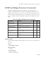
GVRP and Bridge Extension Commands . . . . . . . . . . . . . . . . . . . . .
bridge-ext gvrp . . . . . . . . . . . . . . . . . . . . . . . . . . . . . . . . .
show bridge-ext . . . . . . . . . . . . . . . . . . . . . . . . . . . . . . . . .
switchport gvrp . . . . . . . . . . . . . . . . . . . . . . . . . . . . . . . . .
show gvrp configuration . . . . . . . . . . . . . . . . . . . . . . . . . .
garp timer . . . . . . . . . . . . . . . . . . . . . . . . . . . . . . . . . . . . .
show garp timer . . . . . . . . . . . . . . . . . . . . . . . . . . . . . . . . .
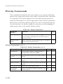
Priority Commands . . . . . . . . . . . . . . . . . . . . . . . . . . . . . . . . . . . . . . .
Priority Commands (Layer 2) . . . . . . . . . . . . . . . . . . . . . . . . . .
queue mode . . . . . . . . . . . . . . . . . . . . . . . . . . . . . . . . . . . .
switchport priority default . . . . . . . . . . . . . . . . . . . . . . . .
queue bandwidth . . . . . . . . . . . . . . . . . . . . . . . . . . . . . . .
queue cos-map . . . . . . . . . . . . . . . . . . . . . . . . . . . . . . . . .
show queue mode . . . . . . . . . . . . . . . . . . . . . . . . . . . . . . .
show queue bandwidth . . . . . . . . . . . . . . . . . . . . . . . . . . .
xviii
4-229
4-230
4-230
4-231
4-232
4-232
4-233
4-234
4-235
4-236
4-237
4-238
4-239
4-239
4-240
4-240
4-241
4-242
4-243
4-244
4-245
4-246
4-247
4-247
4-248
4-249
4-249
4-250
4-251
4-252
4-252
4-253
4-254
4-255
4-256
4-257
4-258
TABLE OF CONTENTS
show queue cos-map . . . . . . . . . . . . . . . . . . . . . . . . . . . . . 4-258
Priority Commands (Layer 3 and 4) . . . . . . . . . . . . . . . . . . . . 4-259
map ip port (Global Configuration) . . . . . . . . . . . . . . . . . 4-259
map ip port (Interface Configuration) . . . . . . . . . . . . . . . 4-260
map ip precedence (Global Configuration) . . . . . . . . . . . 4-261
map ip precedence (Interface Configuration) . . . . . . . . . 4-261
map ip dscp (Global Configuration) . . . . . . . . . . . . . . . . 4-262
map ip dscp (Interface Configuration) . . . . . . . . . . . . . . . 4-263
show map ip port . . . . . . . . . . . . . . . . . . . . . . . . . . . . . . . 4-264
show map ip precedence . . . . . . . . . . . . . . . . . . . . . . . . . . 4-265
show map ip dscp . . . . . . . . . . . . . . . . . . . . . . . . . . . . . . . 4-266
Multicast Filtering Commands . . . . . . . . . . . . . . . . . . . . . . . . . . . . . . . 4-267
IGMP Snooping Commands . . . . . . . . . . . . . . . . . . . . . . . . . 4-268
ip igmp snooping . . . . . . . . . . . . . . . . . . . . . . . . . . . . . . . . 4-268
ip igmp snooping vlan static . . . . . . . . . . . . . . . . . . . . . . . 4-269
ip igmp snooping version . . . . . . . . . . . . . . . . . . . . . . . . . 4-269
show ip igmp snooping . . . . . . . . . . . . . . . . . . . . . . . . . . . 4-270
show mac-address-table multicast . . . . . . . . . . . . . . . . . . 4-271
IGMP Query Commands (Layer 2) . . . . . . . . . . . . . . . . . . . . 4-272
ip igmp snooping querier . . . . . . . . . . . . . . . . . . . . . . . . . 4-272
ip igmp snooping query-count . . . . . . . . . . . . . . . . . . . . . 4-273
ip igmp snooping query-interval . . . . . . . . . . . . . . . . . . . . 4-274
ip igmp snooping query-max-response-time . . . . . . . . . . 4-274
ip igmp snooping router-port-expire-time . . . . . . . . . . . . 4-275
Static Multicast Routing Commands . . . . . . . . . . . . . . . . . . . . 4-276
ip igmp snooping vlan mrouter . . . . . . . . . . . . . . . . . . . . 4-276
show ip igmp snooping mrouter . . . . . . . . . . . . . . . . . . . 4-277
IP Interface Commands . . . . . . . . . . . . . . . . . . . . . . . . . . . . . . . . . . . . 4-278
Basic IP Configuration . . . . . . . . . . . . . . . . . . . . . . . . . . . . . . . 4-278
ip address . . . . . . . . . . . . . . . . . . . . . . . . . . . . . . . . . . . . . 4-279
ip default-gateway . . . . . . . . . . . . . . . . . . . . . . . . . . . . . . . 4-280
ip dhcp restart . . . . . . . . . . . . . . . . . . . . . . . . . . . . . . . . . . . . . . 4-281
show ip interface . . . . . . . . . . . . . . . . . . . . . . . . . . . . . . . . 4-282
show ip redirects . . . . . . . . . . . . . . . . . . . . . . . . . . . . . . . . 4-282
ping . . . . . . . . . . . . . . . . . . . . . . . . . . . . . . . . . . . . . . . . . . 4-283
xix
TABLE OF CONTENTS
DNS Commands . . . . . . . . . . . . . . . . . . . . . . . . . . . . . . . . . . . . . . . . .
ip host . . . . . . . . . . . . . . . . . . . . . . . . . . . . . . . . . . . . . . . .
clear host . . . . . . . . . . . . . . . . . . . . . . . . . . . . . . . . . . . . . .
ip domain-name . . . . . . . . . . . . . . . . . . . . . . . . . . . . . . . .
ip domain-list . . . . . . . . . . . . . . . . . . . . . . . . . . . . . . . . . . .
ip name-server . . . . . . . . . . . . . . . . . . . . . . . . . . . . . . . . . .
ip domain-lookup . . . . . . . . . . . . . . . . . . . . . . . . . . . . . . .
show hosts . . . . . . . . . . . . . . . . . . . . . . . . . . . . . . . . . . . . .
show dns . . . . . . . . . . . . . . . . . . . . . . . . . . . . . . . . . . . . . .
show dns cache . . . . . . . . . . . . . . . . . . . . . . . . . . . . . . . . .
clear dns cache . . . . . . . . . . . . . . . . . . . . . . . . . . . . . . . . .
A
4-284
4-285
4-286
4-287
4-288
4-289
4-290
4-291
4-292
4-292
4-293
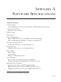
Software Specifications . . . . . . . . . . . . . . . . . . . . . . . . .A-1
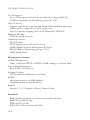
Software Features . . . . . . . . . . . . . . . . . . . . . . . . . . . . . . . . . . . . . . . . . . . A-1
Management Features . . . . . . . . . . . . . . . . . . . . . . . . . . . . . . . . . . . . . . . A-2
Standards . . . . . . . . . . . . . . . . . . . . . . . . . . . . . . . . . . . . . . . . . . . . . . . . . A-2
Management Information Bases . . . . . . . . . . . . . . . . . . . . . . . . . . . . . . . A-3
B
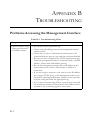
Troubleshooting . . . . . . . . . . . . . . . . . . . . . . . . . . . . . .B-1
Problems Accessing the Management Interface . . . . . . . . . . . . . . . . . . B-1
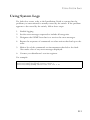
Using System Logs . . . . . . . . . . . . . . . . . . . . . . . . . . . . . . . . . . . . . . . . . . B-3
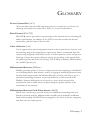
Glossary
Index
xx
TABLES
Table 1-1
Table 1-2
Table 3-1
Table 3-2
Table 3-3
Table 3-4
Table 3-5
Table 3-6
Table 3-7
Table 3-8
Table 3-9
Table 3-10
Table 3-11
Table 3-12
Table 3-13
Table 3-14
Table 3-15
Table 3-16
Table 4-1
Table 4-2
Table 4-3
Table 4-4
Table 4-5
Table 4-6
Table 4-7
Table 4-8
Table 4-9
Table 4-10
Table 4-11
Table 4-12
Table 4-13
Table 4-14
Table 4-15
Table 4-16
Key Features . . . . . . . . . . . . . . . . . . . . . . . . . . . . . . . . . . . . 1-1
System Defaults . . . . . . . . . . . . . . . . . . . . . . . . . . . . . . . . . 1-7
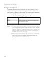
Web Page Configuration Buttons . . . . . . . . . . . . . . . . . . . 3-4
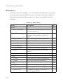
Main Menu . . . . . . . . . . . . . . . . . . . . . . . . . . . . . . . . . . . . . 3-6
Logging Levels . . . . . . . . . . . . . . . . . . . . . . . . . . . . . . . . . 3-39
SNMPv3 Security Models and Levels . . . . . . . . . . . . . . . 3-51
Supported Notification Messages . . . . . . . . . . . . . . . . . . 3-67
HTTPS System Support . . . . . . . . . . . . . . . . . . . . . . . . . 3-82
802.1X Statistics . . . . . . . . . . . . . . . . . . . . . . . . . . . . . . . 3-101
LACP Port Counters . . . . . . . . . . . . . . . . . . . . . . . . . . . 3-135
LACP Internal Configuration Information . . . . . . . . . 3-136
LACP Neighbor Configuration Information . . . . . . . . 3-139
Port Statistics . . . . . . . . . . . . . . . . . . . . . . . . . . . . . . . . . 3-146
Mapping CoS Values to Egress Queues . . . . . . . . . . . . 3-208
CoS Priority Levels . . . . . . . . . . . . . . . . . . . . . . . . . . . . 3-208
Mapping IP Precedence . . . . . . . . . . . . . . . . . . . . . . . . . 3-214
Mapping DSCP Priority . . . . . . . . . . . . . . . . . . . . . . . . . 3-215
Egress Queue Priority Mapping . . . . . . . . . . . . . . . . . . 3-219
General Command Modes . . . . . . . . . . . . . . . . . . . . . . . . 4-8
Configuration Command Modes . . . . . . . . . . . . . . . . . . 4-10
Keystroke Commands . . . . . . . . . . . . . . . . . . . . . . . . . . . 4-11
Command Group Index . . . . . . . . . . . . . . . . . . . . . . . . . 4-12
Line Commands . . . . . . . . . . . . . . . . . . . . . . . . . . . . . . . . 4-14
General Commands . . . . . . . . . . . . . . . . . . . . . . . . . . . . . 4-26
System Management Commands . . . . . . . . . . . . . . . . . . 4-33
Device Designation Commands . . . . . . . . . . . . . . . . . . . 4-33
User Access Commands . . . . . . . . . . . . . . . . . . . . . . . . . 4-35
Default Login Settings . . . . . . . . . . . . . . . . . . . . . . . . . . . 4-36
IP Filter Commands . . . . . . . . . . . . . . . . . . . . . . . . . . . . . 4-38
Web Server Commands . . . . . . . . . . . . . . . . . . . . . . . . . . 4-41
HTTPS System Support . . . . . . . . . . . . . . . . . . . . . . . . . 4-44
Telnet Server Commands . . . . . . . . . . . . . . . . . . . . . . . . 4-45
Secure Shell Commands . . . . . . . . . . . . . . . . . . . . . . . . . 4-47
show ssh - display description . . . . . . . . . . . . . . . . . . . . . 4-56
xxi
TABLES
Table 4-17
Table 4-18
Table 4-19
Table 4-20
Table 4-21
Table 4-22
Table 4-23
Table 4-24
Table 4-25
Table 4-26
Table 4-27
Table 4-28
Table 4-29
Table 4-30
Table 4-31
Table 4-32
Table 4-33
Table 4-34
Table 4-35
Table 4-36
Table 4-37
Table 4-38
Table 4-39
Table 4-40
Table 4-41
Table 4-42
Table 4-43
Table 4-44
Table 4-45
Table 4-46
Table 4-47
Table 4-48
Table 4-49
Table 4-50
Table 4-51
Table 4-52
Table 4-53
xxii
Event Logging Commands . . . . . . . . . . . . . . . . . . . . . . . 4-59
Logging Levels . . . . . . . . . . . . . . . . . . . . . . . . . . . . . . . . . 4-60
show logging flash/ram - display description . . . . . . . . . 4-65
show logging trap - display description . . . . . . . . . . . . . . 4-66
SMTP Alert Commands . . . . . . . . . . . . . . . . . . . . . . . . . 4-67
Time Commands . . . . . . . . . . . . . . . . . . . . . . . . . . . . . . . 4-72
System Status Commands . . . . . . . . . . . . . . . . . . . . . . . . 4-78
Frame Size Commands . . . . . . . . . . . . . . . . . . . . . . . . . . 4-85
Flash/File Commands . . . . . . . . . . . . . . . . . . . . . . . . . . . 4-86
File Directory Information . . . . . . . . . . . . . . . . . . . . . . . 4-91
Authentication Commands . . . . . . . . . . . . . . . . . . . . . . . 4-94
Authentication Sequence Commands . . . . . . . . . . . . . . . 4-94
RADIUS Client Commands . . . . . . . . . . . . . . . . . . . . . . 4-97
TACACS+ Client Commands . . . . . . . . . . . . . . . . . . . . 4-102
Port Security Commands . . . . . . . . . . . . . . . . . . . . . . . . 4-105
802.1X Port Authentication Commands . . . . . . . . . . . 4-107
Access Control List Commands . . . . . . . . . . . . . . . . . . 4-119
IP ACL Commands . . . . . . . . . . . . . . . . . . . . . . . . . . . . 4-119
Egress Queue Priority Mapping . . . . . . . . . . . . . . . . . . 4-134
MAC ACL Commands . . . . . . . . . . . . . . . . . . . . . . . . . 4-137
Mapping CoS Values to MAC ACLs . . . . . . . . . . . . . . 4-146
ACL Information Commands . . . . . . . . . . . . . . . . . . . . 4-149
SNMP Commands . . . . . . . . . . . . . . . . . . . . . . . . . . . . . 4-150
show snmp engine-id - display description . . . . . . . . . . 4-161
show snmp view - display description . . . . . . . . . . . . . 4-163
show snmp group - display description . . . . . . . . . . . . 4-165
show snmp user - display description . . . . . . . . . . . . . . 4-168
Interface Commands . . . . . . . . . . . . . . . . . . . . . . . . . . . 4-169
show interfaces switchport - display description . . . . . 4-181
Mirror Port Commands . . . . . . . . . . . . . . . . . . . . . . . . . 4-182
Rate Limit Commands . . . . . . . . . . . . . . . . . . . . . . . . . . 4-184
Link Aggregation Commands . . . . . . . . . . . . . . . . . . . . 4-186
show lacp counters - display description . . . . . . . . . . . 4-195
show lacp internal - display description . . . . . . . . . . . . 4-195
show lacp neighbors - display description . . . . . . . . . . 4-197
show lacp sysid - display description . . . . . . . . . . . . . . 4-198
Address Table Commands . . . . . . . . . . . . . . . . . . . . . . 4-198
TABLES
Table 4-54
Table 4-55
Table 4-56
Table 4-57
Table 4-58
Table 4-59
Table 4-60
Table 4-61
Table 4-62
Table 4-63
Table 4-64
Table 4-65
Table 4-66
Table 4-67
Table 4-68
Table 4-69
Table 4-70
Table 4-71
Table 4-72
Table 4-73
Table 4-74
Table B-1
Spanning Tree Commands . . . . . . . . . . . . . . . . . . . . . . 4-204
VLAN Commands . . . . . . . . . . . . . . . . . . . . . . . . . . . . . 4-229
Editing VLAN Groups . . . . . . . . . . . . . . . . . . . . . . . . . 4-230
Configuring VLAN Interfaces . . . . . . . . . . . . . . . . . . . . 4-232
Displaying VLAN Information . . . . . . . . . . . . . . . . . . . 4-239
Private VLAN Commands . . . . . . . . . . . . . . . . . . . . . . 4-240
Protocol-based VLAN Commands . . . . . . . . . . . . . . . . 4-242
GVRP and Bridge Extension Commands . . . . . . . . . . 4-247
Priority Commands . . . . . . . . . . . . . . . . . . . . . . . . . . . . 4-252
Priority Commands (Layer 2) . . . . . . . . . . . . . . . . . . . . 4-252
Default CoS Priority Levels . . . . . . . . . . . . . . . . . . . . . . 4-256
Priority Commands (Layer 3 and 4) . . . . . . . . . . . . . . . 4-259
Mapping IP Precedence to CoS Values . . . . . . . . . . . . 4-262
Mapping IP DSCP to CoS Values . . . . . . . . . . . . . . . . . 4-263
Multicast Filtering Commands . . . . . . . . . . . . . . . . . . . 4-267
IGMP Snooping Commands . . . . . . . . . . . . . . . . . . . . . 4-268
IGMP Query Commands (Layer 2) . . . . . . . . . . . . . . . 4-272
Static Multicast Routing Commands . . . . . . . . . . . . . . . 4-276
Basic IP Configuration Commands . . . . . . . . . . . . . . . 4-278
DNS Commands . . . . . . . . . . . . . . . . . . . . . . . . . . . . . . 4-284
show dns cache - display description . . . . . . . . . . . . . . 4-293
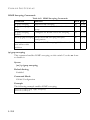
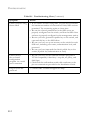
Troubleshooting Chart . . . . . . . . . . . . . . . . . . . . . . . . . . . B-1
xxiii
TABLES
xxiv
FIGURES
Figure 3-1
Figure 3-2
Figure 3-3
Figure 3-4
Figure 3-5
Figure 3-6
Figure 3-7
Figure 3-8
Figure 3-9
Figure 3-10
Figure 3-11
Figure 3-12
Figure 3-13
Figure 3-14
Figure 3-15
Figure 3-16
Figure 3-17
Figure 3-18
Figure 3-19
Figure 3-20
Figure 3-21
Figure 3-22
Figure 3-23
Figure 3-24
Figure 3-25
Figure 3-26
Figure 3-27
Figure 3-28
Figure 3-29
Figure 3-30
Figure 3-31
Figure 3-32
Figure 3-33
Figure 3-34
Figure 3-35
Figure 3-36
Figure 3-37
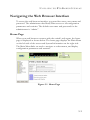
Home Page . . . . . . . . . . . . . . . . . . . . . . . . . . . . . . . . . . . . 3-3
Panel Display . . . . . . . . . . . . . . . . . . . . . . . . . . . . . . . . . . . 3-5
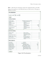
System Information . . . . . . . . . . . . . . . . . . . . . . . . . . . . . 3-15
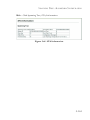
Switch Information . . . . . . . . . . . . . . . . . . . . . . . . . . . . . 3-17
Displaying Bridge Extension Configuration . . . . . . . . . 3-19
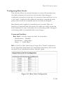
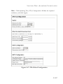
IP Interface Configuration - Manual . . . . . . . . . . . . . . . 3-22
IP Interface Configuration - DHCP . . . . . . . . . . . . . . . 3-23
Configuring Support for Jumbo Frames . . . . . . . . . . . . 3-25
Copy Firmware . . . . . . . . . . . . . . . . . . . . . . . . . . . . . . . . 3-27
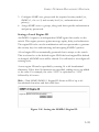
Setting the Startup Code . . . . . . . . . . . . . . . . . . . . . . . . . 3-28
Deleting Files . . . . . . . . . . . . . . . . . . . . . . . . . . . . . . . . . . 3-28
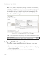
Downloading Configuration Settings for Start-Up . . . . 3-32
Setting the Startup Configuration Settings . . . . . . . . . . . 3-33
Configuring the Console Port . . . . . . . . . . . . . . . . . . . . 3-35
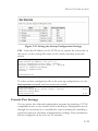
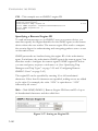
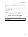
Configuring the Telnet Interface . . . . . . . . . . . . . . . . . . 3-37
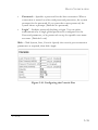
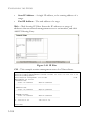
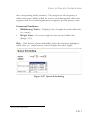
System Logs . . . . . . . . . . . . . . . . . . . . . . . . . . . . . . . . . . . 3-40
Remote Logs . . . . . . . . . . . . . . . . . . . . . . . . . . . . . . . . . . 3-42
Displaying Logs . . . . . . . . . . . . . . . . . . . . . . . . . . . . . . . . 3-43
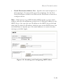
Enabling and Configuring SMTP Alerts . . . . . . . . . . . . 3-45
Resetting the System . . . . . . . . . . . . . . . . . . . . . . . . . . . . 3-46
SNTP Configuration . . . . . . . . . . . . . . . . . . . . . . . . . . . . 3-48
Clock Time Zone . . . . . . . . . . . . . . . . . . . . . . . . . . . . . . 3-49
Enabling the SNMP Agent . . . . . . . . . . . . . . . . . . . . . . . 3-53
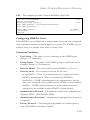
Configuring SNMP Community Strings . . . . . . . . . . . . 3-54
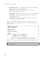
Configuring SNMP Trap Managers . . . . . . . . . . . . . . . . 3-58
Setting the SNMPv3 Engine ID . . . . . . . . . . . . . . . . . . . 3-59
Setting an Engine ID . . . . . . . . . . . . . . . . . . . . . . . . . . . 3-60
Configuring SNMPv3 Users . . . . . . . . . . . . . . . . . . . . . . 3-62
Configuring Remote SNMPv3 Users . . . . . . . . . . . . . . . 3-65
Configuring SNMPv3 Groups . . . . . . . . . . . . . . . . . . . . 3-71
Configuring SNMPv3 Views . . . . . . . . . . . . . . . . . . . . . 3-73
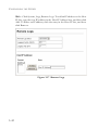
User Accounts . . . . . . . . . . . . . . . . . . . . . . . . . . . . . . . . . 3-76
Authentication Server Settings . . . . . . . . . . . . . . . . . . . . 3-80
HTTPS Settings . . . . . . . . . . . . . . . . . . . . . . . . . . . . . . . . 3-83
SSH Host-Key Settings . . . . . . . . . . . . . . . . . . . . . . . . . . 3-88
SSH Server Settings . . . . . . . . . . . . . . . . . . . . . . . . . . . . . 3-90
Port Security . . . . . . . . . . . . . . . . . . . . . . . . . . . . . . . . . . 3-93
FIGURES
Figure 3-38
Figure 3-39
Figure 3-40
Figure 3-41
Figure 3-42
Figure 3-43
Figure 3-44
Figure 3-45
Figure 3-46
Figure 3-47
Figure 3-48
Figure 3-49
Figure 3-50
Figure 3-51
Figure 3-52
Figure 3-53
Figure 3-54
Figure 3-55
Figure 3-56
Figure 3-57
Figure 3-58
Figure 3-59
Figure 3-60
Figure 3-61
Figure 3-62
Figure 3-63
Figure 3-64
Figure 3-65
Figure 3-66
Figure 3-67
Figure 3-68
Figure 3-69
Figure 3-70
Figure 3-71
Figure 3-72
Figure 3-73
Figure 3-74
xxvi
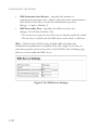
802.1X Global Information . . . . . . . . . . . . . . . . . . . . . . 3-95
802.1X Global Configuration . . . . . . . . . . . . . . . . . . . . . 3-96
802.1X Port Configuration . . . . . . . . . . . . . . . . . . . . . . . 3-98
802.1X Port Statistics . . . . . . . . . . . . . . . . . . . . . . . . . . 3-102
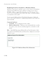
IP Filter . . . . . . . . . . . . . . . . . . . . . . . . . . . . . . . . . . . . . 3-104
Selecting ACL Type . . . . . . . . . . . . . . . . . . . . . . . . . . . 3-107
ACL Configuration - Standard IP . . . . . . . . . . . . . . . . 3-108
ACL Configuration - Extended IP . . . . . . . . . . . . . . . . 3-110
ACL Configuration - MAC . . . . . . . . . . . . . . . . . . . . . . 3-112
Selecting ACL Mask Types . . . . . . . . . . . . . . . . . . . . . . 3-114
ACL Mask Configuration - IP . . . . . . . . . . . . . . . . . . . 3-116
ACL Mask Configuration - MAC . . . . . . . . . . . . . . . . . 3-118
ACL Port Binding . . . . . . . . . . . . . . . . . . . . . . . . . . . . . 3-120
Port - Port Information . . . . . . . . . . . . . . . . . . . . . . . . 3-122
Port - Port Configuration . . . . . . . . . . . . . . . . . . . . . . . 3-126
Static Trunk Configuration . . . . . . . . . . . . . . . . . . . . . . 3-129
LACP Trunk Configuration . . . . . . . . . . . . . . . . . . . . . 3-131
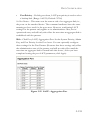
LACP - Aggregation Port . . . . . . . . . . . . . . . . . . . . . . . 3-133
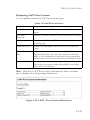
LACP - Port Counters Information . . . . . . . . . . . . . . . 3-135
LACP - Port Internal Information . . . . . . . . . . . . . . . . 3-138
LACP - Port Neighbors Information . . . . . . . . . . . . . . 3-140
Port Broadcast Control . . . . . . . . . . . . . . . . . . . . . . . . . 3-142
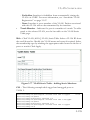
Mirror Port Configuration . . . . . . . . . . . . . . . . . . . . . . 3-144
Rate Limit Configuration . . . . . . . . . . . . . . . . . . . . . . . 3-145
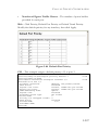
Port Statistics . . . . . . . . . . . . . . . . . . . . . . . . . . . . . . . . . 3-151
Static Addresses . . . . . . . . . . . . . . . . . . . . . . . . . . . . . . . 3-154
Dynamic Addresses . . . . . . . . . . . . . . . . . . . . . . . . . . . . 3-155
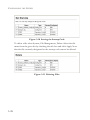
Address Aging . . . . . . . . . . . . . . . . . . . . . . . . . . . . . . . . 3-156
STA Information . . . . . . . . . . . . . . . . . . . . . . . . . . . . . . 3-161
STA Global Configuration . . . . . . . . . . . . . . . . . . . . . . 3-167
STA Port Information . . . . . . . . . . . . . . . . . . . . . . . . . 3-172
STA Port Configuration . . . . . . . . . . . . . . . . . . . . . . . . 3-175
MSTP VLAN Configuration . . . . . . . . . . . . . . . . . . . . 3-178
MSTP Port Information . . . . . . . . . . . . . . . . . . . . . . . . 3-180
MSTP Port Configuration . . . . . . . . . . . . . . . . . . . . . . 3-184
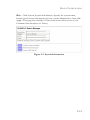
Globally Enabling GVRP . . . . . . . . . . . . . . . . . . . . . . . 3-189
VLAN Basic Information . . . . . . . . . . . . . . . . . . . . . . . 3-190
FIGURES
Figure 3-75
Figure 3-76
Figure 3-77
Figure 3-78
Figure 3-79
Figure 3-80
Figure 3-81
Figure 3-82
Figure 3-83
Figure 3-84
Figure 3-85
Figure 3-86
Figure 3-87
Figure 3-88
Figure 3-89
Figure 3-90
Figure 3-91
Figure 3-92
Figure 3-93
Figure 3-94
Figure 3-95
Figure 3-96
Figure 3-97
Figure 3-98
Figure 3-99
Figure 3-100
Figure 3-101
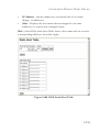
VLAN Current Table . . . . . . . . . . . . . . . . . . . . . . . . . . 3-191
VLAN Static List - Creating VLANs . . . . . . . . . . . . . . 3-193
VLAN Static Table - Adding Static Members . . . . . . . 3-195
VLAN Static Membership by Port . . . . . . . . . . . . . . . . 3-196
VLAN Port Configuration . . . . . . . . . . . . . . . . . . . . . . 3-199
Private VLAN Status . . . . . . . . . . . . . . . . . . . . . . . . . . . 3-201
Private VLAN Link Status . . . . . . . . . . . . . . . . . . . . . . 3-201
Protocol VLAN Configuration . . . . . . . . . . . . . . . . . . . 3-203
Protocol VLAN Port Configuration . . . . . . . . . . . . . . 3-205
Default Port Priority . . . . . . . . . . . . . . . . . . . . . . . . . . . 3-207
Traffic Classes . . . . . . . . . . . . . . . . . . . . . . . . . . . . . . . . 3-209
Queue Mode . . . . . . . . . . . . . . . . . . . . . . . . . . . . . . . . . 3-210
Queue Scheduling . . . . . . . . . . . . . . . . . . . . . . . . . . . . . 3-211
IP Precedence/DSCP Priority Status . . . . . . . . . . . . . . 3-213
IP Precedence Priority . . . . . . . . . . . . . . . . . . . . . . . . . 3-214
IP DSCP Priority . . . . . . . . . . . . . . . . . . . . . . . . . . . . . . 3-216
IP Port Priority Status . . . . . . . . . . . . . . . . . . . . . . . . . . 3-218
IP Port Priority . . . . . . . . . . . . . . . . . . . . . . . . . . . . . . . 3-218
ACL CoS Priority . . . . . . . . . . . . . . . . . . . . . . . . . . . . . 3-220
IGMP Configuration . . . . . . . . . . . . . . . . . . . . . . . . . . . 3-225
Multicast Router Port Information . . . . . . . . . . . . . . . 3-226
Static Multicast Router Port Configuration . . . . . . . . . 3-228
Displaying Port Members of Multicast Services . . . . . 3-229
Specifying Multicast Port Membership . . . . . . . . . . . . 3-230
DNS General Configuration . . . . . . . . . . . . . . . . . . . . . 3-233
DNS Static Host Table . . . . . . . . . . . . . . . . . . . . . . . . . 3-235
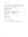
DNS Cache . . . . . . . . . . . . . . . . . . . . . . . . . . . . . . . . . . 3-237
xxvii
FIGURES
xxviii
CHAPTER 1
INTRODUCTION
This switch provides a broad range of features for Layer 2 switching. It
includes a management agent that allows you to configure the features
listed in this manual. The default configuration can be used for most of the
features provided by this switch. However, there are many options that you
should configure to maximize the switch’s performance for your particular
network environment.
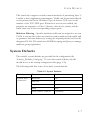
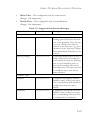
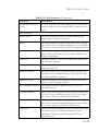
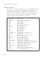
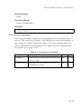
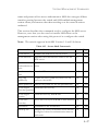
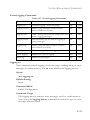
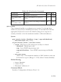
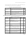
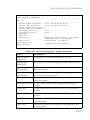
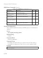
Key Features
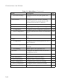
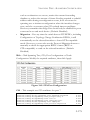
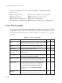
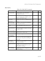
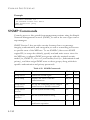
Table 1-1 Key Features
Feature
Description
Configuration
Backup and
Restore
Backup to TFTP server
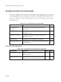
Authentication
Console, Telnet, web – User name / password, RADIUS,
TACACS+
Web – SSL/HTTPS; Telnet – SSH
SNMP v1/2c - Community strings
SNMP version 3 – MD5 or SHA password
Port – IEEE 802.1X, MAC address filtering
Access Control
Lists
Supports up to 32 IP or MAC ACLs
DHCP Client
Supported
DNS
Client and proxy service
Port
Configuration
Speed and duplex mode
1-1
INTRODUCTION
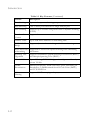
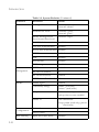
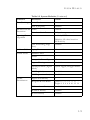
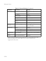
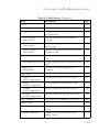
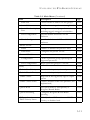
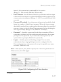
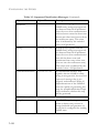
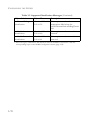
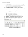
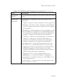
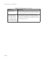
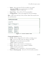
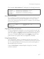
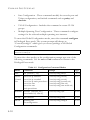
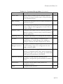
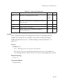
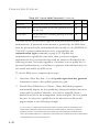
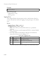
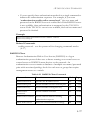
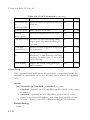
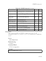
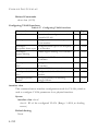
Table 1-1 Key Features (Continued)
Feature
Description
Rate Limiting
Input and output rate limiting per port
Port Mirroring
One or more ports mirrored to single analysis port
Port Trunking
Supports up to 4 trunks using either static or dynamic trunking
(LACP)
Broadcast Storm Supported
Control
Address Table
Up to 16K MAC addresses in forwarding table
IEEE 802.1D
Bridge
Supports dynamic data switching and addresses learning
Store-and-Forwa Supported to ensure wire-speed switching while eliminating
rd Switching
bad frames
1-2
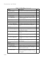
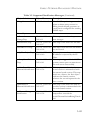
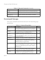
Spanning Tree
Algorithm
Supports standard STP, Rapid Spanning Tree Protocol (RSTP),
and Multiple Spanning Trees (MSTP)
Virtual LANs
Up to 255 using IEEE 802.1Q, port-based, protocol-based, or
private VLANs
Traffic
Prioritization
Default port priority, traffic class map, queue scheduling, IP
Precedence, or Differentiated Services Code Point (DSCP),
and TCP/UDP Port
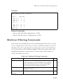
Multicast
Filtering
Supports IGMP snooping and query
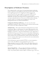
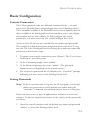
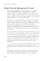
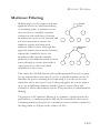
DESCRIPTION OF SOFTWARE FEATURES
Description of Software Features
The switch provides a wide range of advanced performance enhancing
features. Broadcast storm suppression prevents broadcast traffic storms
from engulfing the network. Untagged (port-based), tagged, and
protocol-based VLANs, plus support for automatic GVRP VLAN
registration provide traffic security and efficient use of network
bandwidth. CoS priority queueing ensures the minimum delay for moving
real-time multimedia data across the network. While multicast filtering
provides support for real-time network applications. Some of the
management features are briefly described below.
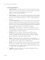
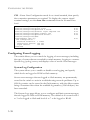
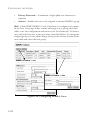
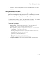
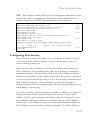
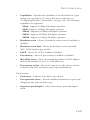
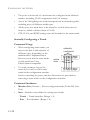
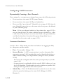
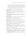
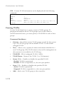
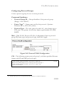
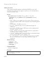
Configuration Backup and Restore – You can save the current
configuration settings to a file on a TFTP server, and later download this
file to restore the switch configuration settings.
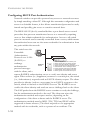
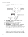
Authentication – This switch authenticates management access via the
console port, Telnet or web browser. User names and passwords can be
configured locally or can be verified via a remote authentication server (i.e.,
RADIUS or TACACS+). Port-based authentication is also supported via
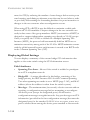
the IEEE 802.1X protocol. This protocol uses Extensible Authentication
Protocol over LANs (EAPOL) to request user credentials from the 802.1X
client, and then uses the EAP between the switch and the authentication
server to verify the client’s right to access the network via an authentication
server (i.e., RADIUS server).
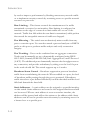
Other authentication options include HTTPS for secure management
access via the web, SSH for secure management access over a
Telnet-equivalent connection, SNMP Version 3, IP address filtering for
SNMP/web/Telnet management access, and MAC address filtering for
port access.
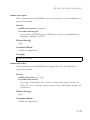
Access Control Lists – ACLs provide packet filtering for IP frames
(based on address, protocol, TCP/UDP port number or TCP control
code) or any frames (based on MAC address or Ethernet type). ACLs can
1-3
INTRODUCTION
by used to improve performance by blocking unnecessary network traffic
or to implement security controls by restricting access to specific network
resources or protocols.
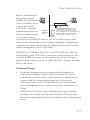
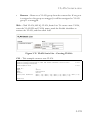
Rate Limiting – This feature controls the maximum rate for traffic
transmitted or received on an interface. Rate limiting is configured on
interfaces at the edge of a network to limit traffic into or out of the
network. Traffic that falls within the rate limit is transmitted, while packets
that exceed the acceptable amount of traffic are dropped.
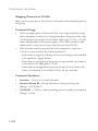
Port Mirroring – The switch can unobtrusively mirror traffic from any
port to a monitor port. You can then attach a protocol analyzer or RMON
probe to this port to perform traffic analysis and verify connection
integrity.
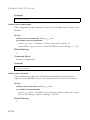
Port Trunking – Ports can be combined into an aggregate connection.
Trunks can be manually set up or dynamically configured using IEEE
802.3-2002 (formerly IEEE 802.3ad) Link Aggregation Control Protocol
(LACP). The additional ports dramatically increase the throughput across
any connection, and provide redundancy by taking over the load if a port
in the trunk should fail. The switch supports up to 4 trunks.
Broadcast Storm Control – Broadcast suppression prevents broadcast
traffic from overwhelming the network. When enabled on a port, the level
of broadcast traffic passing through the port is restricted. If broadcast
traffic rises above a pre-defined threshold, it will be throttled until the level
falls back beneath the threshold.
Static Addresses – A static address can be assigned to a specific interface
on this switch. Static addresses are bound to the assigned interface and will
not be moved. When a static address is seen on another interface, the
address will be ignored and will not be written to the address table. Static
addresses can be used to provide network security by restricting access for
a known host to a specific port.
1-4
DESCRIPTION OF SOFTWARE FEATURES
IEEE 802.1D Bridge – The switch supports IEEE 802.1D transparent
bridging. The address table facilitates data switching by learning addresses,
and then filtering or forwarding traffic based on this information. The
address table supports up to 16K addresses.
Store-and-Forward Switching – The switch copies each frame into its
memory before forwarding them to another port. This ensures that all
frames are a standard Ethernet size and have been verified for accuracy
with the cyclic redundancy check (CRC). This prevents bad frames from
entering the network and wasting bandwidth.
To avoid dropping frames on congested ports, the switch provides 256 KB
for frame buffering. This buffer can queue packets awaiting transmission
on congested networks.
Spanning Tree Algorithm – The switch supports these spanning tree
protocols:
Spanning Tree Protocol (STP, IEEE 802.1D) – This protocol provides
loop detection and recovery by allowing two or more redundant
connections to be created between a pair of LAN segments. When there
are multiple physical paths between segments, this protocol will choose a
single path and disable all others to ensure that only one route exists
between any two stations on the network. This prevents the creation of
network loops. However, if the chosen path should fail for any reason, an
alternate path will be activated to maintain the connection.
Rapid Spanning Tree Protocol (RSTP, IEEE 802.1w) – This protocol
reduces the convergence time for network topology changes to about 3 to
5 seconds, compared to 30 seconds or more for the older IEEE 802.1D
STP standard. It is intended as a complete replacement for STP, but can
still interoperate with switches running the older standard by automatically
reconfiguring ports to STP-compliant mode if they detect STP protocol
messages from attached devices.
1-5
INTRODUCTION
Multiple Spanning Tree Protocol (MSTP, IEEE 802.1s) – This protocol is
a direct extension of RSTP. It can provide an independent spanning tree
for different VLANs. It simplifies network management, provides for even
faster convergence than RSTP by limiting the size of each region, and
prevents VLAN members from being segmented from the rest of the
group (as sometimes occurs with IEEE 802.1D STP).
Virtual LANs – The switch supports up to 255 VLANs. A Virtual LAN is
a collection of network nodes that share the same collision domain
regardless of their physical location or connection point in the network.
The switch supports tagged VLANs based on the IEEE 802.1Q standard.
Members of VLAN groups can be dynamically learned via GVRP, or ports
can be manually assigned to a specific set of VLANs. This allows the
switch to restrict traffic to the VLAN groups to which a user has been
assigned. By segmenting your network into VLANs, you can:
•
•
•
•
•
Eliminate broadcast storms which severely degrade performance in a
flat network.
Simplify network management for node changes/moves by remotely
configuring VLAN membership for any port, rather than having to
manually change the network connection.
Provide data security by restricting all traffic to the originating VLAN.
Use private VLANs to restrict traffic to pass only between data ports
and the uplink ports, thereby isolating adjacent ports within the same
VLAN, and allowing you to limit the total number of VLANs that need
to be configured.
Use protocol VLANs to restrict traffic to specified interfaces based on
protocol type.
Traffic Prioritization – This switch prioritizes each packet based on the
required level of service, using eight priority queues with strict or Weighted
Round Robin Queuing. It uses IEEE 802.1p and 802.1Q tags to prioritize
incoming traffic based on input from the end-station application. These
functions can be used to provide independent priorities for delay-sensitive
data and best-effort data.
1-6
SYSTEM DEFAULTS
This switch also supports several common methods of prioritizing layer 3/
4 traffic to meet application requirements. Traffic can be prioritized based
on the priority bits in the IP frame’s Type of Service (ToS) octet or the
number of the TCP/UDP port. When these services are enabled, the
priorities are mapped to a Class of Service value by the switch, and the
traffic then sent to the corresponding output queue.
Multicast Filtering – Specific multicast traffic can be assigned to its own
VLAN to ensure that it does not interfere with normal network traffic and
to guarantee real-time delivery by setting the required priority level for the
designated VLAN. The switch uses IGMP Snooping and Query to manage
multicast group registration.
System Defaults
The switch’s system defaults are provided in the configuration file
“Factory_Default_Config.cfg.” To reset the switch defaults, this file
should be set as the startup configuration file (page 3-32).
The following table lists some of the basic system defaults.
Table 1-2 System Defaults
Function
Parameter
Default
Console Port
Connection
Baud Rate
auto
Data bits
8
Stop bits
1
Parity
none
Local Console Timeout
0 (disabled)
1-7
INTRODUCTION
Table 1-2 System Defaults (Continued)
Function
Parameter
Default
Authentication
Privileged Exec Level
Username “admin”
Password “admin”
Normal Exec Level
Username “guest”
Password “guest”
Enable Privileged Exec
from Normal Exec Level
Password “super”
RADIUS Authentication
Disabled
TACACS Authentication
Disabled
802.1X Port Authentication Disabled
Web
Management
HTTPS
Enabled
SSH
Disabled
Port Security
Disabled
IP Filtering
Disabled
HTTP Server
Enabled
HTTP Port Number
80
HTTP Secure Server
Enabled
HTTP Secure Port Number 443
SNMP
SNMP Agent
Enabled
Community Strings
“public” (read only)
“private” (read/write)
Traps
Authentication traps: enabled
Link-up-down events: enabled
SNMP V3
View: defaultview
Group: public (read only); private
(read/write)
1-8
Port
Configuration
Admin Status
Enabled
Flow Control*
Disabled
Rate Limiting
Input and output limits
Disabled
SYSTEM DEFAULTS
Table 1-2 System Defaults (Continued)
Function
Parameter
Default
Port Trunking
Static Trunks
None
LACP (all ports)
Disabled
Broadcast Storm Status
Protection
Broadcast Limit Rate
Spanning Tree
Algorithm
Status
Enabled
1042 packets per second
Enabled, MSTP
(Defaults: All values based on
IEEE 802.1s)
Fast Forwarding (Edge
Port)
Disabled
Address Table
Aging Time
300 seconds
Virtual LANs
Default VLAN
1
PVID
1
Acceptable Frame Type
All
Ingress Filtering
Disabled
Switchport Mode (Egress
Mode)
Hybrid: tagged/untagged frames
GVRP (global)
Disabled
GVRP (port interface)
Disabled
Ingress Port Priority
0
Weighted Round Robin
Queue: 0 1 2 3 4 5 6 7
Weight: 1 2 4 6 8 10 12 14
IP Precedence Priority
Disabled
IP DSCP Priority
Disabled
IP Port Priority
Disabled
Traffic
Prioritization
1-9
INTRODUCTION
Table 1-2 System Defaults (Continued)
Function
Parameter
Default
IP Settings
Management. VLAN
Any VLAN configured with an IP
address
IP Address
0.0.0.0
Subnet Mask
255.0.0.0
Default Gateway
0.0.0.0
DHCP
Client: Enabled
DNS
BOOTP
Disabled
Multicast
Filtering
IGMP Snooping
Snooping: Enabled
System Log
Status
Enabled
Messages Logged
Levels 0-7 (all)
Querier: Disabled
Messages Logged to Flash Levels 0-3
SMTP Email
Alerts
Event Handler
Enabled (but no server defined)
SNTP
Clock Synchronization
Disabled
* There are interoperability problems between Flow Control and Head-of-Line
(HOL) blocking for the switch ASIC; Flow Control is therefore not
supported for this switch.
1-10
CHAPTER 2
INITIAL CONFIGURATION
Connecting to the Switch
Configuration Options
The switch includes a built-in network management agent. The agent
offers a variety of management options, including SNMP, RMON and a
web-based interface. A PC may also be connected directly to the switch for
configuration and monitoring via a command line interface (CLI).
Note: The IP address for this switch is obtained via DHCP by default.
To change this address, see “Setting an IP Address” on page 2-6.
The switch’s HTTP web agent allows you to configure switch parameters,
monitor port connections, and display statistics using a standard web
browser such as Netscape Navigator version 6.2 and higher or Microsoft
IE version 5.0 and higher. The switch’s web management interface can be
accessed from any computer attached to the network.
The CLI program can be accessed by a direct connection to the RS-232
serial console port on the switch, or remotely by a Telnet connection over
the network.
The switch’s management agent also supports SNMP (Simple Network
Management Protocol). This SNMP agent permits the switch to be
managed from any system in the network using network management
software such as SMC EliteView.
2-1
INITIAL CONFIGURATION
The switch’s web interface, CLI configuration program, and SNMP agent
allow you to perform the following management functions:
•
•
•
•
•
Set user names and passwords
Set an IP interface for any VLAN
Configure SNMP parameters
Enable/disable any port
Configure the bandwidth of any port by limiting input or output rates
•
Control port access through IEEE 802.1X security or static address
filtering
•
Filter packets using Access Control Lists (ACLs)
•
•
•
•
•
•
•
•
•
•
•
Configure up to 255 IEEE 802.1Q VLANs
Enable GVRP automatic VLAN registration
Configure IGMP multicast filtering
Upload and download system firmware via TFTP
Upload and download switch configuration files via TFTP
Configure Spanning Tree parameters
Configure Class of Service (CoS) priority queuing
Configure up to 4 static or LACP trunks
Enable port mirroring
Set broadcast storm control on any port
Display system information and statistics
Required Connections
The switch provides an RS-232 serial port that enables a connection to a
PC or terminal for monitoring and configuring the switch. A null-modem
console cable is provided with the switch.
Attach a VT100-compatible terminal, or a PC running a terminal
emulation program to the switch. You can use the console cable provided
with this package, or use a null-modem cable that complies with the wiring
assignments shown in the Installation Guide.
2-2
CONNECTING TO THE SWITCH
To connect a terminal to the console port, complete the following steps:
1. Connect the console cable to the serial port on a terminal, or a PC
running terminal emulation software, and tighten the captive retaining
screws on the DB-9 connector.
2. Connect the other end of the cable to the RS-232 serial port on the
switch.
3. Make sure the terminal emulation software is set as follows:
•
•
•
•
•
•
Select the appropriate serial port (COM port 1 or COM port 2).
Set to any of the following baud rates: 9600, 19200, 38400, 57600,
115200 (Note: Set to 9600 baud if want to view all the system
initialization messages.).
Set the data format to 8 data bits, 1 stop bit, and no parity.
Set flow control to none.
Set the emulation mode to VT100.
When using HyperTerminal, select Terminal keys, not Windows
keys.
Notes: 1. When using HyperTerminal with Microsoft® Windows® 2000,
make sure that you have Windows 2000 Service Pack 2 or later
installed. Windows 2000 Service Pack 2 fixes the problem of
arrow keys not functioning in HyperTerminal’s VT100
emulation. See www.microsoft.com for information on
Windows 2000 service packs.
2. Refer to “Line Commands” on page 4-14 for a complete
description of console configuration options.
3. Once you have set up the terminal correctly, the console login
screen will be displayed.
For a description of how to use the CLI, see “Using the Command Line
Interface” on page 4-1. For a list of all the CLI commands and detailed
information on using the CLI, refer to “Command Groups” on page 4-12.
2-3
INITIAL CONFIGURATION
Remote Connections
Prior to accessing the switch’s onboard agent via a network connection,
you must first configure it with a valid IP address, subnet mask, and default
gateway using a console connection, DHCP or BOOTP protocol.
The IP address for this switch is obtained via DHCP by default. To
manually configure this address or enable dynamic address assignment via
DHCP or BOOTP, see “Setting an IP Address” on page 2-6.
Note: You can manage the switch through the same IP address using any
of the 10 Gigabit data ports (Ports 1-8) or though the Fast
Ethernet management port (Port 9). The management port allows
you to build a separate network for management tasks. It acn also
provide faster management access when the data ports are heavily
loaded.
Note: This switch supports four concurrent Telnet/SSH sessions.
After configuring the switch’s IP parameters, you can access the onboard
configuration program from anywhere within the attached network. The
onboard configuration program can be accessed using Telnet from any
computer attached to the network. The switch can also be managed by any
computer using a web browser (Internet Explorer 5.0 or above, or
Netscape Navigator 6.2 or above), or from a network computer using
SNMP network management software.
Note: The onboard program only provides access to basic configuration
functions. To access the full range of SNMP management
functions, you must use SNMP-based network management
software.
2-4
BASIC CONFIGURATION
Basic Configuration
Console Connection
The CLI program provides two different command levels — normal
access level (Normal Exec) and privileged access level (Privileged Exec).
The commands available at the Normal Exec level are a limited subset of
those available at the Privileged Exec level and allow you to only display
information and use basic utilities. To fully configure the switch
parameters, you must access the CLI at the Privileged Exec level.
Access to both CLI levels are controlled by user names and passwords.
The switch has a default user name and password for each level. To log
into the CLI at the Privileged Exec level using the default user name and
password, perform these steps:
1. To initiate your console connection, press <Enter>. The “User Access
Verification” procedure starts.
2. At the Username prompt, enter “admin.”
3. At the Password prompt, also enter “admin.” (The password
characters are not displayed on the console screen.)
4. The session is opened and the CLI displays the “Console#” prompt
indicating you have access at the Privileged Exec level.
Setting Passwords
Note: If this is your first time to log into the CLI program, you should
define new passwords for both default user names using the
“username” command, record them and put them in a safe place.
Passwords can consist of up to 8 alphanumeric characters and are case
sensitive. To prevent unauthorized access to the switch, set the passwords
as follows:
1. Open the console interface with the default user name and password
“admin” to access the Privileged Exec level.
2-5
INITIAL CONFIGURATION
2. Type “configure” and press <Enter>.
3. Type “username guest password 0 password,” for the Normal Exec
level, where password is your new password. Press <Enter>.
4. Type “username admin password 0 password,” for the Privileged Exec
level, where password is your new password. Press <Enter>.
Username: admin
Password:
CLI session with the 8*10GE L2 Switch is opened.
To end the CLI session, enter [Exit].
Console#configure
Console(config)#username guest password 0 [password]
Console(config)#username admin password 0 [password]
Console(config)#
Setting an IP Address
You must establish IP address information for the switch to obtain
management access through the network. This can be done in either of the
following ways:
Manual — You have to input the information, including IP address and
subnet mask. If your management station is not in the same IP subnet as
the switch, you will also need to specify the default gateway router.
Dynamic — The switch sends IP configuration requests to BOOTP or
DHCP address allocation servers on the network.
Manual Configuration
You can manually assign an IP address to the switch. You may also need to
specify a default gateway that resides between this device and management
stations that exist on another network segment. Valid IP addresses consist
of four decimal numbers, 0 to 255, separated by periods. Anything outside
this format will not be accepted by the CLI program.
Note: The IP address for this switch is obtained via DHCP by default.
2-6
BASIC CONFIGURATION
Before you can assign an IP address to the switch, you must obtain the
following information from your network administrator:
•
•
•
IP address for the switch
Default gateway for the network
Network mask for this network
To assign an IP address to the switch, complete the following steps:
1. From the Global Configuration mode prompt, type “interface vlan 1”
to access the interface-configuration mode. Press <Enter>.
2. Type “ip address ip-address netmask,” where “ip-address” is the switch
IP address and “netmask” is the network mask for the network. Press
<Enter>.
3. Type “exit” to return to the global configuration mode prompt. Press
<Enter>.
4. To set the IP address of the default gateway for the network to which
the switch belongs, type “ip default-gateway gateway,” where “gateway”
is the IP address of the default gateway. Press <Enter>.
Console(config)#interface vlan 1
Console(config-if)#ip address 192.168.1.5 255.255.255.0
Console(config-if)#exit
Console(config)#ip default-gateway 192.168.1.254
Console(config)#
Dynamic Configuration
If you select the “bootp” or “dhcp” option, IP will be enabled but will not
function until a BOOTP or DHCP reply has been received. You therefore
need to use the “ip dhcp restart client” command to start broadcasting
service requests. Requests will be sent periodically in an effort to obtain IP
configuration information. (BOOTP and DHCP values can include the IP
address, subnet mask, and default gateway.)
2-7
INITIAL CONFIGURATION
If the “bootp” or “dhcp” option is saved to the startup-config file (step 6),
then the switch will start broadcasting service requests as soon as it is
powered on.
To automatically configure the switch by communicating with BOOTP or
DHCP address allocation servers on the network, complete the following
steps:
1. From the Global Configuration mode prompt, type “interface vlan 1”
to access the interface-configuration mode. Press <Enter>.
2. At the interface-configuration mode prompt, use one of the following
commands:
•
To obtain IP settings via DHCP, type “ip address dhcp” and press
<Enter>.
•
To obtain IP settings via BOOTP, type “ip address bootp” and
press <Enter>.
3. Type “end” to return to the Privileged Exec mode. Press <Enter>.
4. Type “ip dhcp restart client” to begin broadcasting service requests.
Press <Enter>.
5. Wait a few minutes, and then check the IP configuration settings by
typing the “show ip interface” command. Press <Enter>.
2-8
BASIC CONFIGURATION
6. Then save your configuration changes by typing “copy running-config
startup-config.” Enter the startup file name and press <Enter>.
Console(config)#interface vlan 1
Console(config-if)#ip address dhcp
Console(config-if)#end
Console#ip dhcp restart client
Console#show ip interface
IP address and netmask: 192.168.1.54 255.255.255.0 on VLAN 1,
and address mode: DHCP.
Console#copy running-config startup-config
Startup configuration file name []: startup
\Write to FLASH Programming.
\Write to FLASH finish.
Success.
Enabling SNMP Management Access
The switch can be configured to accept management commands from
Simple Network Management Protocol (SNMP) applications such as SMC
EliteView. You can configure the switch to (1) respond to SNMP requests
or (2) generate SNMP traps.
When SNMP management stations send requests to the switch (either to
return information or to set a parameter), the switch provides the
requested data or sets the specified parameter. The switch can also be
configured to send information to SNMP managers (without being
requested by the managers) through trap messages, which inform the
manager that certain events have occurred.
The switch includes an SNMP agent that supports SNMP version 1, 2c,
and 3 clients. To provide management access for version 1 or 2c clients,
you must specify a community string. The switch provides a default MIB
View (i.e., an SNMPv3 construct) for the default “public” community
string that provides read access to the entire MIB tree, and a default view
for the “private” community string that provides read/write access to the
entire MIB tree. However, you may assign new views to version 1 or 2c
community strings that suit your specific security requirements (see page
3-72).
2-9
INITIAL CONFIGURATION
Community Strings (for SNMP version 1 and 2c clients)
Community strings are used to control management access to SNMP
version 1 and 2c stations, as well as to authorize SNMP stations to receive
trap messages from the switch. You therefore need to assign community
strings to specified users, and set the access level.
The default strings are:
•
public - with read-only access. Authorized management stations are
only able to retrieve MIB objects.
•
private - with read-write access. Authorized management stations are
able to both retrieve and modify MIB objects.
To prevent unauthorized access to the switch from SNMP version 1 or 2c
clients, it is recommended that you change the default community strings.
To configure a community string, complete the following steps:
1. From the Privileged Exec level global configuration mode prompt,
type “snmp-server community string mode,” where “string” is the
community access string and “mode” is rw (read/write) or ro (read
only). Press <Enter>. (Note that the default mode is read only.)
2. To remove an existing string, simply type “no snmp-server community
string,” where “string” is the community access string to remove. Press
<Enter>.
Console(config)#snmp-server community admin rw
Console(config)#snmp-server community private
Console(config)#
Note: If you do not intend to support access to SNMP version 1 and 2c
clients, we recommend that you delete both of the default
community strings. If there are no community strings, then SNMP
management access from SNMP v1 and v2c clients is disabled.
2-10
BASIC CONFIGURATION
Trap Receivers
You can also specify SNMP stations that are to receive traps from the
switch. To configure a trap receiver, use the “snmp-server host” command.
From the Privileged Exec level global configuration mode prompt, type:
“snmp-server host host-address community-string
[version {1 | 2c | 3 {auth | noauth | priv}}]”
where “host-address” is the IP address for the trap receiver,
“community-string” specifies access rights for a version 1/2c host, or is
the user name of a version 3 host, “version” indicates the SNMP client
version, and “auth | noauth | priv” means that authentication, no
authentication, or authentication and privacy is used for v3 clients.
Then press <Enter>. For a more detailed description of these parameters,
see “snmp-server host” on page 4-155. The following example creates a
trap host for each type of SNMP client.
Console(config)#snmp-server host 10.1.19.23 batman
Console(config)#snmp-server host 10.1.19.98 robin version 2c
Console(config)#snmp-server host 10.1.19.34 barbie version 3 auth
Console(config)#
Configuring Access for SNMP Version 3 Clients
To configure management access for SNMPv3 clients, you need to first
create a view that defines the portions of MIB that the client can read or
write, assign the view to a group, and then assign the user to a group. The
following example creates one view called “mib-2” that includes the entire
MIB-2 tree branch, and then another view that includes the IEEE 802.1d
bridge MIB. It assigns these respective read and read/write views to a
group call “r&d” and specifies group authentication via MD5 or SHA. In
2-11
INITIAL CONFIGURATION
the last step, it assigns a v3 user to this group, indicating that MD5 will be
used for authentication, provides the password “greenpeace” for
authentication, and the password “einstien” for encryption.
Console(config)#snmp-server
Console(config)#snmp-server
Console(config)#snmp-server
Console(config)#snmp-server
priv des56 einstien
Console(config)#
view mib-2 1.3.6.1.2.1 included
view 802.1d 1.3.6.1.2.1.17 included
group r&d v3 auth mib-2 802.1d
user steve r&d v3 auth md5 greenpeace
For a more detailed explanation on how to configure the switch for access
from SNMP v3 clients, refer to “Simple Network Management Protocol”
on page 3-50, or refer to the specific CLI commands for SNMP starting on
page 4-150.
Saving Configuration Settings
Configuration commands only modify the running configuration file and
are not saved when the switch is rebooted. To save all your configuration
changes in nonvolatile storage, you must copy the running configuration
file to the start-up configuration file using the “copy” command.
To save the current configuration settings, enter the following command:
1. From the Privileged Exec mode prompt, type “copy running-config
startup-config” and press <Enter>.
2. Enter the name of the start-up file. Press <Enter>.
Console#copy running-config startup-config
Startup configuration file name []: startup
\Write to FLASH Programming.
\Write to FLASH finish.
Success.
Console#
2-12
MANAGING SYSTEM FILES
Managing System Files
The switch’s flash memory supports three types of system files that can be
managed by the CLI program, web interface, or SNMP. The switch’s file
system allows files to be uploaded and downloaded, copied, deleted, and
set as a start-up file.
The three types of files are:
•
Configuration — This file type stores system configuration
information and is created when configuration settings are saved.
Saved configuration files can be selected as a system start-up file or can
be uploaded via TFTP to a server for backup. The file named
“Factory_Default_Config.cfg” contains all the system default settings
and cannot be deleted from the system. If the system is booted with
the factory default settings, the switch will also create a file named
“startup1.cfg” that contains all system settings, including information
about the unit identifier and MAC address. The configuration settings
from the factory defaults configuration file are copied to this file,
which is then used to boot the switch. See “Saving or Restoring
Configuration Settings” on page 3-30 for more information. See
“Saving or Restoring Configuration Settings” on page 3-30 for more
information.
•
Operation Code — System software that is executed after boot-up,
also known as run-time code. This code runs the switch operations and
provides the CLI and web management interfaces. See “Managing
Firmware” on page 3-25 for more information.
•
Diagnostic Code — Software that is run during system boot-up, also
known as POST (Power On Self-Test).
Due to the size limit of the flash memory, the switch supports only two
operation code files. However, you can have as many diagnostic code files
and configuration files as available flash memory space allows.
2-13
INITIAL CONFIGURATION
In the system flash memory, one file of each type must be set as the
start-up file. During a system boot, the diagnostic and operation code files
set as the start-up file are run, and then the start-up configuration file is
loaded.
Note that configuration files should be downloaded using a file name that
reflects the contents or usage of the file settings. If you download directly
to the running-config, the system will reboot, and the settings will have to
be copied from the running-config to a permanent file.
2-14
CHAPTER 3
CONFIGURING THE SWITCH
Using the Web Interface
This switch provides an embedded HTTP web agent. Using a web browser
you can configure the switch and view statistics to monitor network
activity. The web agent can be accessed by any computer on the network
using a standard web browser (Internet Explorer 5.0 or above, or Netscape
Navigator 6.2 or above).
Note: You can also use the Command Line Interface (CLI) to manage
the switch over a serial connection to the console port or via
Telnet. For more information on using the CLI, refer to Chapter 4
“Command Line Interface.”
Prior to accessing the switch from a web browser, be sure you have first
performed the following tasks:
1.Configure the switch with a valid IP address, subnet mask, and default
gateway using an out-of-band serial connection, BOOTP or DHCP
protocol. (See “Setting an IP Address” on page 2-6.)
2. Set user names and passwords using an out-of-band serial connection.
Access to the web agent is controlled by the same user names and
passwords as the onboard configuration program. (See “Setting
Passwords” on page 2-5.)
3. After you enter a user name and password, you will have access to the
system configuration program.
Notes: 1. You are allowed three attempts to enter the correct password;
on the third failed attempt the current connection is
terminated.
3-1
CONFIGURING THE SWITCH
2. If you log into the web interface as guest (Normal Exec level),
you can view the configuration settings or change the guest
password. If you log in as “admin” (Privileged Exec level), you
can change the settings on any page.
3. If the path between your management station and this switch
does not pass through any device that uses the Spanning Tree
Algorithm, then you can set the switch port attached to your
management station to fast forwarding (i.e., enable Admin
Edge Port) to improve the switch’s response time to
management commands issued through the web interface. See
“Configuring Interface Settings” on page 3-172.
3-2
NAVIGATING THE WEB BROWSER INTERFACE
Navigating the Web Browser Interface
To access the web-browser interface you must first enter a user name and
password. The administrator has Read/Write access to all configuration
parameters and statistics. The default user name and password for the
administrator is “admin.”
Home Page
When your web browser connects with the switch’s web agent, the home
page is displayed as shown below. The home page displays the Main Menu
on the left side of the screen and System Information on the right side.
The Main Menu links are used to navigate to other menus, and display
configuration parameters and statistics.
Figure 3-1 Home Page
3-3
CONFIGURING THE SWITCH
Configuration Options
Configurable parameters have a dialog box or a drop-down list. Once a
configuration change has been made on a page, be sure to click on the
Apply button to confirm the new setting. The following table summarizes
the web page configuration buttons.
Table 3-1 Web Page Configuration Buttons
Button
Action
Apply
Sets specified values to the system.
Revert
Cancels specified values and restores current values
prior to pressing “Apply.”
Help
Links directly to web help.
Notes: 1. To ensure proper screen refresh, be sure that Internet Explorer
5.x is configured as follows: Under the menu “Tools / Internet
Options / General / Temporary Internet Files / Settings,” the
setting for item “Check for newer versions of stored pages”
should be “Every visit to the page.”
2. When using Internet Explorer 5.0, you may have to manually
refresh the screen after making configuration changes by
pressing the browser’s refresh button.
3-4
NAVIGATING THE WEB BROWSER INTERFACE
Panel Display
The web agent displays an image of the switch’s ports. The Mode can be
set to display different information for the ports, including Active (i.e., up
or down), Duplex (i.e., half or full duplex), or Flow Control1. Clicking on
the image of a port opens the Port Configuration page as described on
page 3-125.
Figure 3-2 Panel Display
1. There are interoperability problems between Flow Control and Head-of-Line (HOL) blocking for the
switch ASIC; Flow Control is therefore not supported for this switch.
3-5
CONFIGURING THE SWITCH
Main Menu
Using the onboard web agent, you can define system parameters, manage
and control the switch, and all its ports, or monitor network conditions.
The following table briefly describes the selections available from this
program.
Table 3-2 Main Menu
Menu
Description
System
3-14
System Information
Provides basic system description, including
contact information
3-14
Switch Information
Shows the number of ports, hardware/
firmware version numbers, and power
status
3-16
Bridge Extension
Shows the bridge extension parameters
3-18
IP Configuration
Sets the IP address for management access
3-20
Jumbo Frames
Enables support for jumbo frames
3-24
File Management
3-25
Copy Operation
Allows the transfer and copying files
3-25
Delete
Allows deletion of files from the flash
memory
3-25
Set Startup
Sets the startup file
3-25
Line
3-33
Console
Sets console port connection parameters
3-33
Telnet
Sets Telnet connection parameters
3-36
3-38
Log
3-6
Page
Logs
Sends error messages to a logging process
3-38
System Logs
Stores and displays error messages
3-43
Remote Logs
Configures the logging of messages to a
remote logging process
3-40
NAVIGATING THE WEB BROWSER INTERFACE
Table 3-2 Main Menu (Continued)
Menu
SMTP
Reset
Description
Page
Sends an SMTP client message to a
participating server
3-44
Restarts the switch
3-46
SNTP
3-47
Configuration
Configures SNTP client settings, including a
specified list of servers
Clock Time Zone
Sets the local time zone for the system clock
SNMP
3-47
3-49
3-50
Configuration
Configures community strings and related
trap functions
3-53
Agent Status
Enables or disables SNMP
3-53
SNMPv3
3-58
Engine ID
Sets the SNMP v3 engine ID
3-59
Remote Engine ID
Sets the SNMP v3 engine ID on a remote
device
3-60
Users
Configures SNMP v3 users
3-61
Remote Users
Configures SNMP v3 users on a remote
device
3-63
Groups
Configures SNMP v3 groups
3-66
Views
Configures SNMP v3 views
3-72
User Accounts
Configures user names, passwords, and
access levels
3-75
Authentication Settings
Configures authentication sequence,
RADIUS and TACACS
3-76
HTTPS Settings
Configures secure HTTP settings
3-81
Security
3-53
SSH
Settings
3-84
Configures Secure Shell server settings
3-89
3-7
CONFIGURING THE SWITCH
Table 3-2 Main Menu (Continued)
Menu
Host-Key Settings
Port Security
802.1X
Description
Generates the host key pair (public and
private)
3-87
Configures per port security, including
status, response for security breach, and
maximum allowed MAC addresses
3-91
Port authentication
3-94
Information
Displays global configuration settings
3-95
Configuration
Configures global configuration parameters
3-96
Port Configuration
Sets the authentication mode for individual
ports
3-97
Statistics
Displays protocol statistics for the selected
port
3-101
ACL
3-105
Configuration
Configures packet filtering based on IP or
MAC addresses
3-105
Mask Configuration
Controls the order in which ACL rules are
checked
3-113
Port Binding
Binds a port to the specified ACL
3-119
Configures IP addresses that are allowed
management access
3-103
IP Filter
Port
3-8
Page
3-121
Port Information
Displays port connection status
3-121
Trunk Information
Displays trunk connection status
3-121
Port Configuration
Configures port connection settings
3-125
Trunk Configuration
Configures trunk connection settings
3-125
Trunk Membership
Specifies ports to group into static trunks
3-128
NAVIGATING THE WEB BROWSER INTERFACE
Table 3-2 Main Menu (Continued)
Menu
Description
LACP
Page
3-127
Configuration
Allows ports to dynamically join trunks
3-130
Aggregation Port
Configures parameters for link aggregation
group members
3-132
Port Counters
Information
Displays statistics for LACP protocol
messages
3-135
Port Internal
Information
Displays settings and operational state for
the local side
3-136
Port Neighbors
Information
Displays settings and operational state for
the remote side
3-139
Sets the broadcast storm threshold for each
port
3-141
Trunk Broadcast Control Sets the broadcast storm threshold for each
trunk
3-141
Mirror Port
Configuration
3-143
Port Broadcast Control
Sets the source and target ports for
mirroring
Rate Limit
3-145
Input
Port Configuration
Sets the input rate limit for each port
3-145
Input
Trunk Configuration
Sets the input rate limit for each trunk
3-145
Output
Port Configuration
Sets the output rate limit for each port
3-145
Output
Trunk Configuration
Sets the output rate limit for each trunk
3-145
Lists Ethernet and RMON port statistics
3-146
Port Statistics
Address Table
3-152
Static Addresses
Displays entries for interface, address or
VLAN
3-153
Dynamic Addresses
Displays or edits static entries in the
Address Table
3-154
3-9
CONFIGURING THE SWITCH
Table 3-2 Main Menu (Continued)
Menu
Address Aging
Description
Page
Sets timeout for dynamically learned entries 3-156
Spanning Tree
3-156
STA
Information
Displays STA values used for the bridge
3-158
Configuration
Configures global bridge settings for STP,
RSTP and MSTP
3-163
Port Information
Displays individual port settings for STA
3-168
Trunk Information
Displays individual trunk settings for STA
3-168
Port Configuration
Configures individual port settings for STA 3-172
Trunk Configuration
Configures individual trunk settings for
STA
3-172
VLAN Configuration
Configures priority and VLANs for a
spanning tree instance
3-176
Port Information
Displays port settings for a specified MST
instance
3-180
Trunk Information
Displays trunk settings for a specified MST
instance
3-180
Port Configuration
Configures port settings for a specified MST 3-182
instance
Trunk Configuration
Configures trunk settings for a specified
MST instance
MSTP
VLAN
3-182
3-184
802.1Q VLAN
3-10
GVRP Status
Enables GVRP VLAN registration protocol 3-189
Basic Information
Displays information on the VLAN type
supported by this switch
Current Table
Shows the current port members of each
3-190
VLAN and whether or not the port is tagged
or untagged
3-189
NAVIGATING THE WEB BROWSER INTERFACE
Table 3-2 Main Menu (Continued)
Menu
Description
Page
Static List
Used to create or remove VLAN groups
3-192
Static Table
Modifies the settings for an existing VLAN 3-194
Static Membership by Configures membership type for interfaces,
Port
including tagged, untagged or forbidden
3-196
Port Configuration
Specifies default PVID and VLAN
attributes
3-197
Trunk Configuration
Specifies default trunk VID and VLAN
attributes
3-197
Status
Enables or disables the private VLAN
3-200
Link Status
Configures the private VLAN
3-201
Configuration
Creates a protocol group, specifying the
supported protocols
3-203
Port Configuration
Maps a protocol group to a VLAN
3-204
Private VLAN
Protocol VLAN
Priority
3-206
Default Port Priority
Sets the default priority for each port
3-206
Default Trunk Priority
Sets the default priority for each trunk
3-206
Traffic Classes
Maps IEEE 802.1p priority tags to output
queues
3-208
Traffic Classes Status
Enables/disables traffic class priorities (not
implemented)
Queue Mode
Sets queue mode to strict priority or
Weighted Round-Robin
3-209
Queue Scheduling
Configures Weighted Round Robin
queueing
3-210
IP Precedence/
DSCP Priority Status
Globally selects IP Precedence or DSCP
Priority, or disables both.
3-213
NA
3-11
CONFIGURING THE SWITCH
Table 3-2 Main Menu (Continued)
Menu
Description
Page
IP Precedence Priority
Sets IP Type of Service priority, mapping
the precedence tag to a class-of-service
value
3-213
IP DSCP Priority
Sets IP Differentiated Services Code Point
priority, mapping a DSCP tag to a
class-of-service value
3-215
IP Port Priority Status
Globally enables or disables IP Port Priority 3-217
IP Port Priority
Sets TCP/UDP port priority, defining the
socket number and associated
class-of-service value
3-217
ACL CoS Priority
Sets the CoS value and corresponding
output queue for packets matching an ACL
rule
3-219
IGMP Snooping
3-12
3-221
IGMP Configuration
Enables multicast filtering; configures
parameters for multicast query
3-223
Multicast Router
Port Information
Displays the ports that are attached to a
neighboring multicast router for each
VLAN ID
3-226
Static Multicast Router
Port Configuration
Assigns ports that are attached to a
neighboring multicast router
3-227
IP Multicast Registration Displays all multicast groups active on this
Table
switch, including multicast IP addresses and
VLAN ID
3-228
IGMP Member
Port Table
3-229
Indicates multicast addresses associated
with the selected VLAN
NAVIGATING THE WEB BROWSER INTERFACE
Table 3-2 Main Menu (Continued)
Menu
Description
DNS
Page
3-231
General Configuration
Enables DNS; configures domain name and 3-231
domain list; and specifies IP address of
name servers for dynamic lookup
Static Host Table
Configures static entries for domain name
to address mapping
3-234
Cache
Displays cache entries discovered by
designated name servers
3-236
3-13
CONFIGURING THE SWITCH
Basic Configuration
Displaying System Information
You can easily identify the system by displaying the device name, location
and contact information.
Field Attributes
•
System Name – Name assigned to the switch system.
•
Object ID – MIB II object ID for switch’s network management
subsystem.
•
Location – Specifies the system location.
•
Contact – Administrator responsible for the system.
•
System Up Time – Length of time the management agent has been
up.
These additional parameters are displayed for the CLI.
•
•
•
•
•
•
•
•
•
•
3-14
MAC Address – The physical layer address for this switch.
Web server – Shows if management access via HTTP is enabled.
Web server port – Shows the TCP port number used by the web
interface.
Web secure server – Shows if management access via HTTPS is
enabled.
Web secure server port – Shows the TCP port used by the HTTPS
interface.
Telnet server – Shows if management access via Telnet is enabled.
Telnet server port – Shows the TCP port used by the Telnet interface.
Authentication login – Shows the user login authentication sequence.
Jumbo Frame – Shows if jumbo frames are enabled.
POST result – Shows results of the power-on self-test
BASIC CONFIGURATION
Web – Click System, System Information. Specify the system name,
location, and contact information for the system administrator, then click
Apply. (This page also includes a Telnet button that allows access to the
Command Line Interface via Telnet.)
Figure 3-3 System Information
3-15
CONFIGURING THE SWITCH
CLI – Specify the hostname, location and contact information.
Console(config)#hostname R&D 5
4-34
Console(config)#snmp-server location WC 9
4-154
Console(config)#snmp-server contact Ted
4-153
Console(config)#exit
Console#show system
4-83
System Description: 8*10GE L2 Switch
System OID String: 1.3.6.1.4.1.259.6.10.76
System Information
System Up Time:
0 days, 4 hours, 5 minutes, and 56.31 seconds
System Name:
[NONE]
System Location:
[NONE]
System Contact:
[NONE]
MAC Address (Unit1):
00-0C-DB-21-11-33
Web Server:
Enabled
Web Server Port:
80
Web Secure Server:
Enabled
Web Secure Server Port: 443
Telnet Server:
Enable
Telnet Server Port:
23
Authentication login:
local RADIUS none
Jumbo Frame:
Disabled
POST Result:
DUMMY Test 1 .................
UART Loopback Test ...........
DRAM Test ....................
Timer Test ...................
PCI Device 1 Test ............
I2C Bus Initialization .......
Switch Int Loopback Test .....
PASS
PASS
PASS
PASS
PASS
PASS
PASS
Done All Pass.
Console#
Displaying Switch Hardware/Software Versions
Use the Switch Information page to display hardware/firmware version
numbers for the main board and management software, as well as the
power status of the system.
Field Attributes
Main Board
3-16
•
Serial Number – The serial number of the switch.
•
Number of Ports – Number of built-in ports.
•
Hardware Version – Hardware version of the main board.
BASIC CONFIGURATION
•
Internal Power Status – Displays the status of the internal power
supply.
Management Software
•
EPLD Version – Version number of EEPROM Programmable Logic
Device.
•
Loader Version – Version number of loader code.
•
Boot-ROM Version – Version of Power-On Self-Test (POST) and
boot code.
•
Operation Code Version – Version number of runtime code.
•
Role – Shows that this switch is operating as Master (i.e., stand alone).
These additional parameters are displayed for the CLI.
•
Unit ID – Unit number in stack.
•
Redundant Power Status – Displays the status of the redundant
power supply.
Web – Click System, Switch Information.
Figure 3-4 Switch Information
3-17
CONFIGURING THE SWITCH
CLI – Use the following command to display version information.
Console#show version
Unit 1
Serial Number:
Hardware Version:
EPLD Version:
Number of Ports:
Main Power Status:
Redundant Power Status:
4-84
A000000022
R01
1.00
9
Up
Not present
Agent (Master)
Unit ID:
Loader Version:
Boot ROM Version:
Operation Code Version:
1
3.0.0.2
3.0.0.6
3.0.0.4
Console#
Displaying Bridge Extension Capabilities
The Bridge MIB includes extensions for managed devices that support
Multicast Filtering, Traffic Classes, and Virtual LANs. You can access these
extensions to display default settings for the key variables.
Field Attributes
3-18
•
Extended Multicast Filtering Services – This switch does not
support the filtering of individual multicast addresses based on GMRP
(GARP Multicast Registration Protocol).
•
Traffic Classes – This switch provides mapping of user priorities to
multiple traffic classes. (Refer to “Class of Service Configuration” on
page 3-206.)
•
Static Entry Individual Port – This switch allows static filtering for
unicast and multicast addresses. (Refer to “Setting Static Addresses”
on page 3-153.)
•
VLAN Learning – This switch uses Independent VLAN Learning
(IVL), where each port maintains its own filtering database.
BASIC CONFIGURATION
•
Configurable PVID Tagging – This switch allows you to override
the default Port VLAN ID (PVID used in frame tags) and egress status
(VLAN-Tagged or Untagged) on each port. (Refer to “VLAN
Configuration” on page 3-184.)
•
Local VLAN Capable – This switch does not support multiple local
bridges outside of the scope of 802.1Q defined VLANs.
•
GMRP – GARP Multicast Registration Protocol (GMRP) allows
network devices to register endstations with multicast groups. This
switch does not support GMRP; it uses the Internet Group
Management Protocol (IGMP) to provide automatic multicast
filtering.
Web – Click System, Bridge Extension.
Figure 3-5 Displaying Bridge Extension Configuration
3-19
CONFIGURING THE SWITCH
CLI – Enter the following command.
Console#show bridge-ext
Max support VLAN numbers:
Max support VLAN ID:
Extended multicast filtering services:
Static entry individual port:
VLAN learning:
Configurable PVID tagging:
Local VLAN capable:
Traffic classes:
Global GVRP status:
GMRP:
Console#
4-248
256
4094
No
Yes
IVL
Yes
No
Enabled
Disabled
Disabled
Setting the Switch’s IP Address
An IP address may be used for management access to the switch over your
network. By default, the switch uses DHCP to assign IP settings to VLAN
1 on the switch. If you wish to manually configure IP settings, you need to
set an IP address and subnet mask that is compatible with your network.
You may also need to establish a default gateway between the switch and
management stations that exist on another network segment.
You can manually configure a specific IP address, or direct the device to
obtain an address from a BOOTP or DHCP server. Valid IP addresses
consist of four decimal numbers, 0 to 255, separated by periods. Anything
outside this format will not be accepted by the CLI program.
Command Attributes
•
3-20
Management VLAN – ID of the configured VLAN (1-4093). This is
the only VLAN through which you can gain management access to the
switch. By default, all ports on the switch are members of VLAN 1, so
a management station can be connected to any port on the switch.
However, if other VLANs are configured and you change the
Management VLAN, you may lose management access to the switch.
In this case, you should reconnect the management station to a port
that is a member of the Management VLAN.
BASIC CONFIGURATION
•
IP Address Mode – Specifies whether IP functionality is enabled via
manual configuration (Static), Dynamic Host Configuration Protocol
(DHCP), or Boot Protocol (BOOTP). If DHCP/BOOTP is enabled,
IP will not function until a reply has been received from the server.
Requests will be broadcast periodically by the switch for an IP address.
(DHCP/BOOTP values can include the IP address, subnet mask, and
default gateway.)
•
IP Address – Address of the VLAN to which the management station
is attached. (Note you can manage the switch through any configured
IP interface.) Valid IP addresses consist of four numbers, 0 to 255,
separated by periods. (Default: 0.0.0.0)
•
Subnet Mask – This mask identifies the host address bits used for
routing to specific subnets. (Default: 255.0.0.0)
•
Gateway IP address – IP address of the gateway router between this
device and management stations that exist on other network segments.
(Default: 0.0.0.0)
•
MAC Address – The MAC address of this switch.
•
Restart DHCP – Requests a new IP address from the DHCP server.
3-21
CONFIGURING THE SWITCH
Manual Configuration
Web – Click System, IP Configuration. Select the VLAN through which
the management station is attached, set the IP Address Mode to “Static.”
Enter the IP address, subnet mask and gateway, then click Apply.
Figure 3-6 IP Interface Configuration - Manual
CLI – Specify the management interface, IP address and default gateway.
Console#config
Console(config)#interface vlan 1
Console(config-if)#ip address 10.1.0.253 255.255.255.0
Console(config-if)#exit
Console(config)#ip default-gateway 10.1.0.254
Console(config)#
4-170
4-279
4-280
Using DHCP/BOOTP
If your network provides DHCP/BOOTP services, you can configure the
switch to be dynamically configured by these services.
3-22
BASIC CONFIGURATION
Web – Click System, IP Configuration. Specify the VLAN to which the
management station is attached, set the IP Address Mode to DHCP or
BOOTP. Click Apply to save your changes. Then click Restart DHCP to
immediately request a new address. Note that the switch will also broadcast
a request for IP configuration settings on each power reset.
Figure 3-7 IP Interface Configuration - DHCP
Note: If you lose your management connection, make a console
connection to the switch and enter “show ip interface” to
determine the new switch address.
CLI – Specify the management interface, and set the IP address mode to
DHCP or BOOTP, and then enter the “ip dhcp restart client” command.
Console#config
Console(config)#interface vlan 1
Console(config-if)#ip address dhcp
Console(config-if)#end
Console#ip dhcp restart
Console#show ip interface
IP Address and Netmask: 192.168.1.58 255.255.255.0 on VLAN
Address Mode:
DHCP
Console#
4-170
4-279
4-281
4-282
1,
3-23
CONFIGURING THE SWITCH
Renewing DCHP – DHCP may lease addresses to clients indefinitely or
for a specific period of time. If the address expires or the switch is moved
to another network segment, you will lose management access to the
switch. In this case, you can reboot the switch or submit a client request to
restart DHCP service via the CLI.
Web – If the address assigned by DHCP is no longer functioning, you will
not be able to renew the IP settings via the web interface. You can only
restart DHCP service via the web interface if the current address is still
available.
CLI – Enter the following command to restart DHCP service.
Console#ip dhcp restart
Console#
4-281
Configuring Support for Jumbo Frames
The switch provides more efficient throughput for large sequential data
transfers by supporting jumbo frames up to 9000 bytes. Compared to
standard Ethernet frames that run only up to 1.5 KB, using jumbo frames
significantly reduces the per-packet overhead required to process protocol
encapsulation fields.
Command Usage
To use jumbo frames, both the source and destination end nodes (such as a
computer or server) must support this feature. Also, when the connection
is operating at full duplex, all switches in the network between the two end
nodes must be able to accept the extended frame size. And for half-duplex
connections, all devices in the collision domain would need to support
jumbo frames.
Command Attributes
•
3-24
Jumbo Packet Status – Configures support for jumbo frames.
(Default: Disabled)
BASIC CONFIGURATION
Web – Click System, Jumbo Frames. Enable or disable support for jumbo
frames, and click Apply.
Figure 3-8 Configuring Support for Jumbo Frames
CLI – This example enables jumbo frames globally for the switch.
Console(config)#jumbo frame
Console(config)#
4-85
Managing Firmware
You can upload/download firmware to or from a TFTP server, or copy
files to and from switch units in a stack. By saving runtime code to a file on
a TFTP server, that file can later be downloaded to the switch to restore
operation. You can also set the switch to use new firmware without
overwriting the previous version. You must specify the method of file
transfer, along with the file type and file names as required.
Command Attributes
•
File Transfer Method – The firmware copy operation includes these
options:
- file to file – Copies a file within the switch directory, assigning it a new
name.
- file to tftp – Copies a file from the switch to a TFTP server.
- tftp to file – Copies a file from a TFTP server to the switch.
•
- file to unit2 – Copies a file from this switch to another unit in the stack.
- unit to file2 – Copies a file from another unit in the stack to this switch.
TFTP Server IP Address – The IP address of a TFTP server.
•
File Type – Specify opcode (operational code) to copy firmware.
2. Stacking is not supported by this switch.
3-25
CONFIGURING THE SWITCH
•
File Name – The file name should not contain slashes (\ or /), the
leading letter of the file name should not be a period (.), and the
maximum length for file names on the TFTP server is 127 characters
or 31 characters for files on the switch. (Valid characters: A-Z, a-z, 0-9,
“.”, “-”, “_”)
•
Source/Destination Unit2 – Stack unit.
Note: Up to two copies of the system software (i.e., the runtime
firmware) can be stored in the file directory on the switch. The
currently designated startup version of this file cannot be deleted.
3-26
BASIC CONFIGURATION
Downloading System Software from a Server
When downloading runtime code, you can specify the destination file
name to replace the current image, or first download the file using a
different name from the current runtime code file, and then set the new
file as the startup file.
Web – Click System, File Management, Copy Operation. Select “tftp to
file” as the file transfer method, enter the IP address of the TFTP server,
set the file type to “opcode,” enter the file name of the software to
download, select a file on the switch to overwrite or specify a new file
name, then click Apply. If you replaced the current firmware used for
startup and want to start using the new operation code, reboot the system
via the System/Reset menu.
Figure 3-9 Copy Firmware
If you download to a new destination file, go to the File Management, Set
Start-Up menu, mark the operation code file used at startup, and click
Apply. To start the new firmware, reboot the system via the System/Reset
menu.
3-27
CONFIGURING THE SWITCH
Figure 3-10 Setting the Startup Code
To delete a file select System, File Management, Delete. Select the file
name from the given list by checking the tick box and click Apply. Note
that the file currently designated as the startup code cannot be deleted.
Figure 3-11 Deleting Files
3-28
BASIC CONFIGURATION
CLI – To download new firmware form a TFTP server, enter the IP
address of the TFTP server, select “config” as the file type, then enter the
source and destination file names. When the file has finished downloading,
set the new file to start up the system, and then restart the switch.
To start the new firmware, enter the “reload” command or reboot the
system.
Console#copy tftp file
TFTP server ip address: 10.1.0.19
Choose file type:
1. config: 2. opcode: <1-2>: 2
Source file name: V3002.bix
Destination file name: V3002
\Write to FLASH Programming.
-Write to FLASH finish.
Success.
Console#config
Console(config)#boot system opcode:V3002
Console(config)#exit
Console#reload
4-87
4-93
4-30
3-29
CONFIGURING THE SWITCH
Saving or Restoring Configuration Settings
You can upload/download configuration settings to/from a TFTP server,
or copy files to and from switch units in a stack. The configuration file can
be later downloaded to restore the switch’s settings.
Command Attributes
•
File Transfer Method – The configuration copy operation includes
these options:
- file to file – Copies a file within the switch directory, assigning it a
new name.
- file to running-config – Copies a file in the switch to the running
configuration.
- file to startup-config – Copies a file in the switch to the startup
configuration.
- file to tftp – Copies a file from the switch to a TFTP server.
- running-config to file – Copies the running configuration to a file.
- running-config to startup-config – Copies the running config to the
startup config.
- running-config to tftp – Copies the running configuration to a TFTP
server.
- startup-config to file – Copies the startup configuration to a file on
the switch.
- startup-config to running-config – Copies the startup config to the
running config.
- startup-config to tftp – Copies the startup configuration to a TFTP
server.
- tftp to file – Copies a file from a TFTP server to the switch.
- tftp to running-config – Copies a file from a TFTP server to the
running config.
- tftp to startup-config – Copies a file from a TFTP server to the
startup config.
3-30
BASIC CONFIGURATION
•
- file to unit3 – Copies a file from this switch to another unit in the
stack.
- unit to file3 – Copies a file from another unit in the stack to this
switch.
TFTP Server IP Address – The IP address of a TFTP server.
•
File Type – Specify config (configuration) to copy configuration
settings.
•
File Name — The configuration file name should not contain slashes
(\ or /), the leading letter of the file name should not be a period (.),
and the maximum length for file names on the TFTP server is 127
characters or 31 characters for files on the switch. (Valid characters:
A-Z, a-z, 0-9, “.”, “-”, “_”)
•
Source/Destination Unit3 – Stack unit.
Note: The maximum number of user-defined configuration files is
limited only by available flash memory space.
3. Stacking is not supported by this switch.
3-31
CONFIGURING THE SWITCH
Downloading Configuration Settings from a Server
You can download the configuration file under a new file name and then
set it as the startup file, or you can specify the current startup
configuration file as the destination file to directly replace it. Note that the
file “Factory_Default_Config.cfg” can be copied to the TFTP server, but
cannot be used as the destination on the switch.
Web – Click System, File Management, Copy Operation. Choose “tftp to
startup-config” or “tftp to file,” and enter the IP address of the TFTP
server. Specify the name of the file to download, select a file on the switch
to overwrite or specify a new file name, and then click Apply.
Figure 3-12 Downloading Configuration Settings for Start-Up
If you download to a new file name using “tftp to startup-config” or “tftp
to file,” the file is automatically set as the start-up configuration file. To use
the new settings, reboot the system via the System/Reset menu. You can
also select any configuration file as the start-up configuration by using the
System/File Management/Set Start-Up page.
3-32
BASIC CONFIGURATION
Figure 3-13 Setting the Startup Configuration Settings
CLI – Enter the IP address of the TFTP server, specify the source file on
the server, set the startup file name on the switch, and then restart the
switch.
Console#copy tftp startup-config
TFTP server ip address: 192.168.1.19
Source configuration file name: config-1
Startup configuration file name [] : startup
\Write to FLASH Programming.
-Write to FLASH finish.
Success.
4-87
Console#reload
To select another configuration file as the start-up configuration, use the
boot system command and then restart the switch.
Console#config
Console(config)#boot system config: startup
Console(config)#exit
Console#reload
4-93
4-30
Console Port Settings
You can access the onboard configuration program by attaching a VT100
compatible device to the switch’s serial console port. Management access
through the console port is controlled by various parameters, including a
password, timeouts, and basic communication settings. These parameters
can be configured via the web or CLI interface.
3-33
CONFIGURING THE SWITCH
Command Attributes
3-34
•
Login Timeout – Sets the interval that the system waits for a user to
log into the CLI. If a login attempt is not detected within the timeout
interval, the connection is terminated for the session.
(Range: 0 - 300 seconds; Default: 0)
•
Exec Timeout – Sets the interval that the system waits until user input
is detected. If user input is not detected within the timeout interval, the
current session is terminated. (Range: 0 - 65535 seconds; Default: 0
seconds)
•
Password Threshold – Sets the password intrusion threshold, which
limits the number of failed logon attempts. When the logon attempt
threshold is reached, the system interface becomes silent for a specified
amount of time (set by the Silent Time parameter) before allowing the
next logon attempt. (Range: 0-120; Default: 3 attempts)
•
Silent Time – Sets the amount of time the management console is
inaccessible after the number of unsuccessful logon attempts has been
exceeded. (Range: 0-65535; Default: 0)
•
Data Bits – Sets the number of data bits per character that are
interpreted and generated by the console port. If parity is being
generated, specify 7 data bits per character. If no parity is required,
specify 8 data bits per character. (Default: 8 bits)
•
Parity – Defines the generation of a parity bit. Communication
protocols provided by some terminals can require a specific parity bit
setting. Specify Even, Odd, or None. (Default: None)
•
Speed – Sets the terminal line’s baud rate for transmit (to terminal) and
receive (from terminal). Set the speed to match the baud rate of the
device connected to the serial port. (Range: 9600, 19200, 38400, 57600,
or 115200 baud, Auto; Default: Auto)
•
Stop Bits – Sets the number of the stop bits transmitted per byte.
(Range: 1-2; Default: 1 stop bit)
BASIC CONFIGURATION
•
Password4 – Specifies a password for the line connection. When a
connection is started on a line with password protection, the system
prompts for the password. If you enter the correct password, the
system shows a prompt. (Default: No password)
•
Login4 – Enables password checking at login. You can select
authentication by a single global password as configured for the
Password parameter, or by passwords set up for specific user-name
accounts. (Default: Local)
Web – Click System, Line, Console. Specify the console port connection
parameters as required, then click Apply.
Figure 3-14 Configuring the Console Port
4. CLI only.
3-35
CONFIGURING THE SWITCH
CLI – Enter Line Configuration mode for the console, then specify the
connection parameters as required. To display the current console port
settings, use the show line command from the Normal Exec level.
Console(config)#line console
Console(config-line)#login local
Console(config-line)#password 0 secret
Console(config-line)#timeout login response 0
Console(config-line)#exec-timeout 0
Console(config-line)#password-thresh 5
Console(config-line)#silent-time 60
Console(config-line)#databits 8
Console(config-line)#parity none
Console(config-line)#speed auto
Console(config-line)#stopbits 1
Console(config-line)#end
Console#show line console
Console configuration:
Password threshold: 5 times
Interactive timeout: Disabled
Login timeout:
Disabled
Silent time:
60
Baudrate:
auto
Databits:
8
Parity:
none
Stopbits:
1
Console#
4-15
4-16
4-17
4-18
4-19
4-20
4-21
4-22
4-23
4-23
4-24
4-25
Telnet Settings
You can access the onboard configuration program over the network using
Telnet (i.e., a virtual terminal). Management access via Telnet can be
enabled/disabled and other various parameters set, including the TCP port
number, timeouts, and a password. These parameters can be configured
via the web or CLI interface.
Command Attributes
3-36
•
Telnet Status – Enables or disables Telnet access to the switch.
(Default: Enabled)
•
Telnet Port Number – Sets the TCP port number for Telnet on the
switch. (Default: 23)
•
Login Timeout – Sets the interval that the system waits for a user to
log into the CLI. If a login attempt is not detected within the timeout
BASIC CONFIGURATION
interval, the connection is terminated for the session.
(Range: 0 - 300 seconds; Default: 300 seconds)
•
Exec Timeout – Sets the interval that the system waits until user input
is detected. If user input is not detected within the timeout interval, the
current session is terminated. (Range: 0 - 65535 seconds; Default: 600
seconds)
•
Password Threshold – Sets the password intrusion threshold, which
limits the number of failed logon attempts. When the logon attempt
threshold is reached, the system interface becomes silent for a specified
amount of time (set by the Silent Time parameter) before allowing the
next logon attempt. (Range: 0-120; Default: 3 attempts)
•
Password5 – Specifies a password for the line connection. When a
connection is started on a line with password protection, the system
prompts for the password. If you enter the correct password, the
system shows a prompt. (Default: No password)
•
Login5 – Enables password checking at login. You can select
authentication by a single global password as configured for the
Password parameter, or by passwords set up for specific user-name
accounts. (Default: Local)
Web – Click System, Line, Telnet. Specify the connection parameters for
Telnet access, then click Apply.
Figure 3-15 Configuring the Telnet Interface
5. CLI only.
3-37
CONFIGURING THE SWITCH
CLI – Enter Line Configuration mode for a virtual terminal, then specify
the connection parameters as required. To display the current virtual
terminal settings, use the show line command from the Normal Exec
level.
Console(config)#line vty
Console(config-line)#login local
Console(config-line)#password 0 secret
Console(config-line)#timeout login response 300
Console(config-line)#exec-timeout 600
Console(config-line)#password-thresh 3
Console(config-line)#end
Console#show line vty
VTY configuration:
Password threshold: 3 times
Interactive timeout: 600 sec
Login timeout:
300 sec
Console#
4-15
4-16
4-17
4-18
4-19
4-20
4-25
Configuring Event Logging
The switch allows you to control the logging of error messages, including
the type of events that are recorded in switch memory, logging to a remote
System Log (syslog) server, and displays a list of recent event messages.
System Log Configuration
The system allows you to enable or disable event logging, and specify
which levels are logged to RAM or flash memory.
Severe error messages that are logged to flash memory are permanently
stored in the switch to assist in troubleshooting network problems. Up to
4096 log entries can be stored in the flash memory, with the oldest entries
being overwritten first when the available log memory (256 kilobytes) has
been exceeded.
The System Logs page allows you to configure and limit system messages
that are logged to flash or RAM memory. The default is for event levels 0
to 3 to be logged to flash and levels 0 to 7 to be logged to RAM.
3-38
BASIC CONFIGURATION
Command Attributes
•
System Log Status – Enables/disables the logging of debug or error
messages to the logging process. (Default: Enabled)
•
Flash Level – Limits log messages saved to the switch’s permanent
flash memory for all levels up to the specified level. For example, if
level 3 is specified, all messages from level 0 to level 3 will be logged to
flash. (Range: 0-7, Default: 3)
Table 3-3 Logging Levels
Level
Level Name
Description
7
Debug
Debugging messages
6
Informational
Informational messages only
5
Notice
Normal but significant condition, such as
cold start
4
Warning
Warning conditions (e.g., return false,
unexpected return)
3
Error
Error conditions (e.g., invalid input, default
used)
2
Critical
Critical conditions (e.g., memory allocation,
or free memory error - resource exhausted)
1
Alert
Immediate action needed
0
Emergency
System unusable
* There are only Level 2, 5 and 6 error messages for the current firmware release.
•
RAM Level – Limits log messages saved to the switch’s temporary
RAM memory for all levels up to the specified level. For example, if
level 7 is specified, all messages from level 0 to level 7 will be logged to
RAM. (Range: 0-7, Default: 7)
Note:The Flash Level must be equal to or less than the RAM Level.
3-39
CONFIGURING THE SWITCH
Web – Click System, Logs, System Logs. Specify System Log Status, set the
level of event messages to be logged to RAM and flash memory, then click
Apply.
Figure 3-16 System Logs
CLI – Enable system logging and then specify the level of messages to be
logged to RAM and flash memory. Use the show logging command to
display the current settings.
Console(config)#logging on
Console(config)#logging history ram 0
Console(config)#exit
Console#show logging ram
Syslog logging:
Disabled
History logging in RAM: level emergencies
Console#
4-59
4-60
4-64
Remote Log Configuration
The Remote Logs page allows you to configure the logging of messages
that are sent to syslog servers or other management stations. You can also
limit the event messages sent to only those messages at or above a
specified level.
Command Attributes
3-40
•
Remote Log Status – Enables/disables the logging of debug or error
messages to the remote logging process. (Default: Disabled)
•
Logging Facility – Sets the facility type for remote logging of syslog
messages. There are eight facility types specified by values of 16 to 23.
BASIC CONFIGURATION
The facility type is used by the syslog server to dispatch log messages
to an appropriate service.
The attribute specifies the facility type tag sent in syslog messages. (See
RFC 3164.) This type has no effect on the kind of messages reported by
the switch. However, it may be used by the syslog server to process
messages, such as sorting or storing messages in the corresponding
database. (Range: 16-23, Default: 23)
•
Logging Trap – Limits log messages that are sent to the remote syslog
server for all levels up to the specified level. For example, if level 3 is
specified, all messages from level 0 to level 3 will be sent to the remote
server. (Range: 0-7, Default: 7)
•
Host IP List – Displays the list of remote server IP addresses that will
receive syslog messages. The maximum number of host IP addresses
allowed is five.
•
Host IP Address – Specifies a new server IP address to add to the
Host IP List.
3-41
CONFIGURING THE SWITCH
Web – Click System, Logs, Remote Logs. To add an IP address to the Host
IP List, type the new IP address in the Host IP Address box, and then click
Add. To delete an IP address, click the entry in the Host IP List, and then
click Remove.
Figure 3-17 Remote Logs
3-42
BASIC CONFIGURATION
CLI – Enter the syslog server host IP address, choose the facility type and
set the logging trap.
Console(config)#logging host 10.1.0.9
Console(config)#logging facility 23
Console(config)#logging trap 4
Console(config)#logging trap
Console(config)#exit
Console#show logging trap
Syslog logging:
Enabled
REMOTELOG status:
Disabled
REMOTELOG facility type:
local use 7
REMOTELOG level type:
Warning conditions
REMOTELOG server ip address: 10.1.0.9
REMOTELOG server ip address: 0.0.0.0
REMOTELOG server ip address: 0.0.0.0
REMOTELOG server ip address: 0.0.0.0
REMOTELOG server ip address: 0.0.0.0
Console#
4-61
4-62
4-63
4-64
Displaying Log Messages
Use the Logs page to scroll through the logged system and event messages.
The switch can store up to 2048 log entries in temporary random access
memory (RAM; i.e., memory flushed on power reset) and up to 4096
entries in permanent flash memory.
Web – Click System, Log, Logs.
Figure 3-18 Displaying Logs
3-43
CONFIGURING THE SWITCH
CLI – This example shows the event message stored in RAM.
Console#show log ram
[1] 00:01:30 2001-01-01
"VLAN 1 link-up notification."
level: 6, module: 5, function: 1, and event no.: 1
[0] 00:01:30 2001-01-01
"Unit 1, Port 1 link-up notification."
level: 6, module: 5, function: 1, and event no.: 1
Console#
4-66
Sending Simple Mail Transfer Protocol Alerts
To alert system administrators of problems, the switch can use SMTP
(Simple Mail Transfer Protocol) to send email messages when triggered by
logging events of a specified level. The messages are sent to specified
SMTP servers on the network and can be retrieved using POP or IMAP
clients.
Command Attributes
3-44
•
Admin Status – Enables/disables the SMTP function. (Default:
Enabled)
•
Email Source Address – Sets the email address used for the “From”
field in alert messages. You may use a symbolic email address that
identifies the switch, or the address of an administrator responsible for
the switch.
•
Severity – Sets the syslog severity threshold level (see table on
page 3-39) used to trigger alert messages. All events at this level or
higher will be sent to the configured email recipients. For example,
using Level 7 will report all events from level 7 to level 0. (Default:
Level 7)
•
SMTP Server List – Specifies a list of up to three recipient SMTP
servers. The switch attempts to connect to the other listed servers if the
first fails. Use the New SMTP Server text field and the Add/Remove
buttons to configure the list.
BASIC CONFIGURATION
•
Email Destination Address List – Specifies the email recipients of
alert messages. You can specify up to five recipients. Use the New
Email Destination Address text field and the Add/Remove buttons to
configure the list.
Web – Click System, Log, SMTP. Enable SMTP, specify a source email
address, and select the minimum severity level. To add an IP address to the
SMTP Server List, type the new IP address in the SMTP Server field and
click Add. To delete an IP address, click the entry in the SMTP Server List
and click Remove. Specify up to five email addresses to receive the alert
messages, and click Apply.
Figure 3-19 Enabling and Configuring SMTP Alerts
3-45
CONFIGURING THE SWITCH
CLI – Enter the IP address of at least one SMTP server, set the syslog
severity level to trigger an email message, and specify the switch (source)
and up to five recipient (destination) email addresses. Enable SMTP with
the logging sendmail command to complete the configuration. Use the
show logging sendmail command to display the current SMTP
configuration.
Console(config)#logging sendmail host 192.168.1.4
Console(config)#logging sendmail level 3
Console(config)#logging sendmail source-email
[email protected]
Console(config)#logging sendmail destination-email
[email protected]
Console(config)#logging sendmail
Console(config)#exit
Console#show logging sendmail
SMTP servers
----------------------------------------------1. 192.168.1.4
4-68
4-69
4-69
4-70
4-71
4-71
SMTP minimum severity level: 4
SMTP destination email addresses
----------------------------------------------1. [email protected]
SMTP source email address: [email protected]
SMTP status:
Console#
Enabled
Resetting the System
Web – Click System, Reset. Click the Reset button to restart the switch.
When prompted, confirm that you want reset the switch.
Figure 3-20 Resetting the System
3-46
BASIC CONFIGURATION
CLI – Use the reload command to restart the switch.
Console#reload
System will be restarted, continue <y/n>?
4-30
Note:When restarting the system, it will always run the Power-On
Self-Test.
Setting the System Clock
Simple Network Time Protocol (SNTP) allows the switch to set its internal
clock based on periodic updates from a time server (SNTP or NTP).
Maintaining an accurate time on the switch enables the system log to
record meaningful dates and times for event entries. You can also manually
set the clock using the CLI. (See “calendar set” on page 4-77.) If the clock
is not set, the switch will only record the time from the factory default set
at the last bootup.
When the SNTP client is enabled, the switch periodically sends a request
for a time update to a configured time server. You can configure up to
three time server IP addresses. The switch will attempt to poll each server
in the configured sequence.
Configuring SNTP
You can configure the switch to send time synchronization requests to
time servers.
Command Attributes
•
SNTP Client – Configures the switch to operate as an SNTP client.
This requires at least one time server to be specified in the SNTP
Server field. (Default: Disabled)
•
SNTP Poll Interval – Sets the interval between sending requests for
a time update from a time server. (Range: 16-16384 seconds;
Default: 16 seconds)
3-47
CONFIGURING THE SWITCH
•
SNTP Server – Sets the IP address for up to three time servers. The
switch attempts to update the time from the first server, if this fails it
attempts an update from the next server in the sequence.
Web – Select SNTP, Configuration. Modify any of the required
parameters, and click Apply.
Figure 3-21 SNTP Configuration
CLI – This example configures the switch to operate as an SNTP client
and then displays the current time and settings.
Console(config)#sntp client
Console(config)#sntp poll 16
Console(config)#sntp server 10.1.0.19 137.82.140.80
128.250.36.2
Console(config)#exit
Console#show sntp
Current time: Jan 6 14:56:05 2004
Poll interval: 60
Current mode: unicast
SNTP status : Enabled
SNTP server 10.1.0.19 137.82.140.80 128.250.36.2
Current server: 128.250.36.2
Console#
3-48
4-72
4-74
4-73
4-75
BASIC CONFIGURATION
Setting the Time Zone
SNTP uses Coordinated Universal Time (or UTC, formerly Greenwich
Mean Time, or GMT) based on the time at the Earth’s prime meridian,
zero degrees longitude. To display a time corresponding to your local time,
you must indicate the number of hours and minutes your time zone is east
(before) or west (after) of UTC.
Command Attributes
•
Current Time – Displays the current time.
•
Name – Assigns a name to the time zone. (Range: 1-29 characters)
•
Hours (0-13) – The number of hours before/after UTC.
•
Minutes (0-59) – The number of minutes before/after UTC.
•
Direction – Configures the time zone to be before (east) or after
(west) UTC.
Web – Select SNTP, Clock Time Zone. Set the offset for your time zone
relative to the UTC, and click Apply.
Figure 3-22 Clock Time Zone
CLI - This example shows how to set the time zone for the system clock.
Console(config)#clock timezone Dhaka hours 6 minute 0 after-UTC
Console(config)#
4-76
3-49
CONFIGURING THE SWITCH
Simple Network Management Protocol
Simple Network Management Protocol (SNMP) is a communication
protocol designed specifically for managing devices on a network.
Equipment commonly managed with SNMP includes switches, routers
and host computers. SNMP is typically used to configure these devices for
proper operation in a network environment, as well as to monitor them to
evaluate performance or detect potential problems.
Managed devices supporting SNMP contain software, which runs locally
on the device and is referred to as an agent. A defined set of variables,
known as managed objects, is maintained by the SNMP agent and used to
manage the device. These objects are defined in a Management
Information Base (MIB) that provides a standard presentation of the
information controlled by the agent. SNMP defines both the format of the
MIB specifications and the protocol used to access this information over
the network.
The switch includes an onboard agent that supports SNMP versions 1, 2c,
and 3. This agent continuously monitors the status of the switch hardware,
as well as the traffic passing through its ports. A network management
station can access this information using software such as SMC EliteView.
Access to the onboard agent from clients using SNMP v1 and v2c is
controlled by community strings. To communicate with the switch, the
management station must first submit a valid community string for
authentication.
Access to the switch using from clients using SNMPv3 provides additional
security features that cover message integrity, authentication, and
encryption; as well as controlling user access to specific areas of the MIB
tree.
The SNMPv3 security structure consists of security models, with each
model having it’s own security levels. There are three security models
defined, SNMPv1, SNMPv2c, and SNMPv3. Users are assigned to
3-50
SIMPLE NETWORK MANAGEMENT PROTOCOL
“groups” that are defined by a security model and specified security levels.
Each group also has a defined security access to set of MIB objects for
reading and writing, which are known as “views.” The switch has a default
view (all MIB objects) and default groups defined for security models v1
and v2c. The following table shows the security models and levels available
and the system default settings.
Table 3-4 SNMPv3 Security Models and Levels
Model Level
Group
Read
View
Write
View
Notify
View
Security
none
Community
string only
defaultview defaultview none
Community
string only
v1
noAuthNoPriv public
defaultview none
(read only)
v1
noAuthNoPriv private
(read/
write)
v1
noAuthNoPriv user defined user defined
v2c
noAuthNoPriv public
defaultview none
(read only)
v2c
noAuthNoPriv private
(read/
write)
v2c
noAuthNoPriv user defined user defined
user defined
user defined Community
string only
v3
noAuthNoPriv user defined user defined
user defined
user defined A user name
match only
user defined
user defined Community
string only
none
Community
string only
defaultview defaultview none
Community
string only
3-51
CONFIGURING THE SWITCH
Table 3-4 SNMPv3 Security Models and Levels (Continued)
Model Level
Group
v3
AuthNoPriv
v3
AuthPriv
Read
View
Write
View
Notify
View
Security
user defined user defined
user defined
user defined Provides user
authentication
via MD5 or
SHA
algorithms
user defined user defined
user defined
user defined Provides user
authentication
via MD5 or
SHA
algorithms
and data
privacy using
DES 56-bit
encryption
Note: The predefined default groups and view can be deleted from the
system. You can then define customized groups and views for the
SNMP clients that require access.
3-52
SIMPLE NETWORK MANAGEMENT PROTOCOL
Enabling the SNMP Agent
Enables SNMPv3 service for all management clients (i.e., versions 1, 2c, 3).
Command Attributes
SNMP Agent Status – Enables SNMP on the switch.
Web – Click SNMP, Agent Status. Enable the SNMP Agent by marking
the Enabled checkbox, and click Apply.
Figure 3-23 Enabling the SNMP Agent
CLI – The following example enables SNMP on the switch.
Console(config)#snmp-server
Console(config)#
4-151
Setting Community Access Strings
You may configure up to five community strings authorized for
management access by clients using SNMP v1 and v2c. All community
strings used for IP Trap Managers should be listed in this table. For
security reasons, you should consider removing the default strings.
Command Attributes
•
SNMP Community Capability – The switch supports up to five
community strings.
•
Current – Displays a list of the community strings currently
configured.
3-53
CONFIGURING THE SWITCH
•
Community String – A community string that acts like a password
and permits access to the SNMP protocol.
Default strings: “public” (read-only), “private” (read/write)
Range: 1-32 characters, case sensitive
•
Access Mode – Specifies the access rights for the community string:
- Read-Only – Authorized management stations are only able to
retrieve MIB objects.
- Read/Write – Authorized management stations are able to both
retrieve and modify MIB objects.
Web – Click SNMP, Configuration. Add new community strings as
required, select the access rights from the Access Mode drop-down list,
then click Add.
Figure 3-24 Configuring SNMP Community Strings
CLI – The following example adds the string “spiderman” with read/write
access.
Console(config)#snmp-server community spiderman rw
Console(config)#
3-54
4-153
SIMPLE NETWORK MANAGEMENT PROTOCOL
Specifying Trap Managers and Trap Types
Traps indicating status changes are issued by the switch to specified trap
managers. You must specify trap managers so that key events are reported
by this switch to your management station (using network management
platforms such as SMC EliteView). You can specify up to five
management stations that will receive authentication failure messages and
other trap messages from the switch.
Command Usage
•
If you specify an SNMP Version 3 host, then the “Trap Manager
Community String” is interpreted as an SNMP user name. If you use
V3 authentication or encryption options (authNoPriv or authPriv), the
user name must first be defined in the SNMPv3 Users page
(page 3-61). Otherwise, the authentication password and/or privacy
password will not exist, and the switch will not authorize SNMP access
for the host. However, if you specify a V3 host with the no
authentication (noAuth) option, an SNMP user account will be
automatically generated, and the switch will authorize SNMP access
for the host.
•
Notifications are issued by the switch as trap messages by default. The
recipient of a trap message does not send a response to the switch.
Traps are therefore not as reliable as inform messages, which include a
request for acknowledgement of receipt. Informs can be used to
ensure that critical information is received by the host. However, note
that informs consume more system resources because they must be
kept in memory until a response is received. Informs also add to
network traffic. You should consider these effects when deciding
whether to issue notifications as traps or informs.
To send an inform to a SNMPv2c host, complete these steps:
1.
2.
3.
4.
Enable the SNMP agent (page 3-53).
Enable trap informs as described in the following pages.
Create a view with the required notification messages (page 3-72).
Create a group that includes the required notify view (page 3-66).
3-55
CONFIGURING THE SWITCH
To send an inform to a SNMPv3 host, complete these steps:
1.
2.
3.
4.
5.
6.
Enable the SNMP agent (page 3-53).
Enable trap informs as described in the following pages.
Create a view with the required notification messages (page 3-72).
Create a group that includes the required notify view (page 3-66).
Specify a remote engine ID where the user resides (page 3-60).
Then configure a remote user (page 3-63).
Command Attributes
•
Trap Manager Capability – This switch supports up to five trap
managers.
•
Current – Displays a list of the trap managers currently configured.
•
Trap Manager IP Address – IP address of a new management station
to receive notification messages.
•
Trap Manager Community String – Specifies a valid community
string for the new trap manager entry. Though you can set this string
in the Trap Managers table, we recommend that you define this string
in the SNMP Configuration page (for Version 1 or 2c clients), or define
a corresponding “User Name” in the SNMPv3 Users page (for Version
3 clients). (Range: 1-32 characters, case sensitive)
•
Trap UDP Port – Specifies the UDP port number used by the trap
manager.
•
Trap Version – Indicates if the user is running SNMP v1, v2c, or v3.
(Default: v1)
•
Trap Security Level – When trap version 3 is selected, you must
specify one of the following security levels. (Default: noAuthNoPriv)
- noAuthNoPriv – There is no authentication or encryption used in
SNMP communications.
- AuthNoPriv – SNMP communications use authentication, but the
data is not encrypted (only available for the SNMPv3 security model).
- AuthPriv – SNMP communications use both authentication and
encryption (only available for the SNMPv3 security model).
3-56
SIMPLE NETWORK MANAGEMENT PROTOCOL
•
Trap Inform – Notifications are sent as inform messages. Note that
this option is only available for version 2c and 3 hosts. (Default: traps
are used)
- Timeout – The number of seconds to wait for an acknowledgment
before resending an inform message. (Range: 0-2147483647
centiseconds; Default: 1500 centiseconds)
- Retry times – The maximum number of times to resend an inform
message if the recipient does not acknowledge receipt. (Range:
0-255; Default: 3)
•
Enable Authentication Traps6 – Issues a notification message to
specified IP trap managers whenever authentication of an SNMP
request fails. (Default: Enabled)
•
Enable Link-up and Link-down Traps6 – Issues a notification
message whenever a port link is established or broken. (Default:
Enabled)
6. These are legacy notifications and therefore when used for SNMP Version 3 hosts, they must be enabled
in conjunction with the corresponding entries in the Notification View (page 3-66).
3-57
CONFIGURING THE SWITCH
Web – Click SNMP, Configuration. Enter the IP address and community
string for each management station that will receive trap messages, specify
the UDP port, SNMP version, trap security level (for v3 clients), trap
inform settings (for v2c/v3 clients), and then click Add. Select the trap
types required using the check boxes for Authentication and Link-up/
down traps, and then click Apply.
Figure 3-25 Configuring SNMP Trap Managers
CLI – This example adds a trap manager and enables authentication traps.
Console(config)#snmp-server host 10.1.19.23 private version 2c
udp-port 162
4-155
Console(config)#snmp-server enable traps authentication
4-158
Configuring SNMPv3 Management Access
To configure SNMPv3 management access to the switch, follow these
steps:
1. If you want to change the default engine ID, do so before configuring
other SNMP parameters.
2. Specify read and write access views for the switch MIB tree.
3-58
SIMPLE NETWORK MANAGEMENT PROTOCOL
3. Configure SNMP user groups with the required security model (i.e.,
SNMP v1, v2c or v3) and security level (i.e., authentication and
privacy).
4. Assign SNMP users to groups, along with their specific authentication
and privacy passwords.
Setting a Local Engine ID
An SNMPv3 engine is an independent SNMP agent that resides on the
switch. This engine protects against message replay, delay, and redirection.
The engine ID is also used in combination with user passwords to generate
the security keys for authenticating and encrypting SNMPv3 packets.
A local engine ID is automatically generated that is unique to the switch.
This is referred to as the default engine ID. If the local engineID is deleted
or changed, all SNMP users will be cleared. You will need to reconfigure all
existing users.
A new engine ID can be specified by entering 10 to 64 hexadecimal
characters. If less than 26 characters are specified, trailing zeroes are added
to the value. For example, the value “1234” is equivalent to “1234”
followed by 60 zeroes.
Web – Click SNMP, SNMPv3, Engine ID. Enter an ID of up to 64
hexadecimal characters and then click Save.
Figure 3-26 Setting the SNMPv3 Engine ID
3-59
CONFIGURING THE SWITCH
CLI – This example sets an SNMPv3 engine ID.
Console(config)#snmp-server engine-id local 12345abcdef
Console(config)#exit
Console#show snmp engine-id
Local SNMP engineID: 8000002a8000000000e8666672
Local SNMP engineBoots: 1
Console#
4-159
4-160
Specifying a Remote Engine ID
To send inform messages to an SNMPv3 user on a remote device, you
must first specify the engine identifier for the SNMP agent on the remote
device where the user resides. The remote engine ID is used to compute
the security digest for authenticating and encrypting packets sent to a user
on the remote host.
SNMP passwords are localized using the engine ID of the authoritative
agent. For informs, the authoritative SNMP agent is the remote agent. You
therefore need to configure the remote agent’s SNMP engine ID before
you can send proxy requests or informs to it. (See “Specifying Trap
Managers and Trap Types” on page 3-55 and “Configuring Remote
SNMPv3 Users” on page 3-63.)
The engine ID can be specified by entering 10 to 64 hexadecimal
characters. If less than 26 characters are specified, trailing zeroes are added
to the value. For example, the value “1234” is equivalent to “1234”
followed by 60 zeroes.
Web – Click SNMP, SNMPv3, Remote Engine ID. Enter an ID of up to
64 hexadecimal characters and then click Save.
Figure 3-27 Setting an Engine ID
3-60
SIMPLE NETWORK MANAGEMENT PROTOCOL
CLI – This example specifies a remote SNMPv3 engine ID.
Console(config)#snmp-server engine-id remote
192.168.1.19 12345abcdef
Console(config)#exit
Console#show snmp engine-id
Local SNMP EngineID: 12345abcdef000000000000000
Local SNMP EngineBoots: 1
Remote SNMP engineID
12345abcdef0
Console#
4-159
4-160
IP address
192.168.1.19
Configuring SNMPv3 Users
Each SNMPv3 user is defined by a unique name. Users must be configured
with a specific security level and assigned to a group. The SNMPv3 group
restricts users to a specific read, write, or notify view.
Command Attributes
•
User Name – The name of user connecting to the SNMP agent.
(Range: 1-32 characters)
•
Group Name – The name of the SNMP group to which the user is
assigned. (Range: 1-32 characters)
•
Security Model – The user security model; SNMP v1, v2c or v3.
•
Security Level – The security level used for the user:
- noAuthNoPriv – There is no authentication or encryption used in
SNMP communications. (This is the default for SNMPv3.)
- AuthNoPriv – SNMP communications use authentication, but the
data is not encrypted (only available for the SNMPv3 security model).
- AuthPriv – SNMP communications use both authentication and
encryption (only available for the SNMPv3 security model).
•
Authentication Protocol – The method used for user authentication.
(Options: MD5, SHA; Default: MD5)
•
Authentication Password – A minimum of eight plain text characters
is required.
•
Privacy Protocol – The encryption algorithm use for data privacy;
only 56-bit DES is currently available.
3-61
CONFIGURING THE SWITCH
•
Privacy Password – A minimum of eight plain text characters is
required.
•
Actions – Enables the user to be assigned to another SNMPv3 group.
Web – Click SNMP, SNMPv3, Users. Click New to configure a user name.
In the New User page, define a name and assign it to a group, then click
Add to save the configuration and return to the User Name list. To delete a
user, check the box next to the user name, then click Delete. To change the
assigned group of a user, click Change Group in the Actions column of the
users table and select the new group.
Figure 3-28 Configuring SNMPv3 Users
3-62
SIMPLE NETWORK MANAGEMENT PROTOCOL
CLI – Use the snmp-server user command to configure a new user name
and assign it to a group.
Console(config)#snmp-server user chris r&d v3 auth md5
greenpeace priv des56 einstien
Console(config)#exit
Console#show snmp user
EngineId: 12345abcdef000000000000000
User Name: chris
Authentication Protocol: MD5
Privacy Protocol: des56
Storage Type: nonvolatile
Row Status: active
4-166
4-168
SNMP remote user
Console#
Configuring Remote SNMPv3 Users
Each SNMPv3 user is defined by a unique name. Users must be configured
with a specific security level and assigned to a group. The SNMPv3 group
restricts users to a specific read and a write view.
To send inform messages to an SNMPv3 user on a remote device, you
must first specify the engine identifier for the SNMP agent on the remote
device where the user resides. The remote engine ID is used to compute
the security digest for authenticating and encrypting packets sent to a user
on the remote host. (See “Specifying Trap Managers and Trap Types” on
page 3-55 and “Specifying a Remote Engine ID” on page 3-60.)
3-63
CONFIGURING THE SWITCH
Command Attributes
•
User Name – The name of user connecting to the SNMP agent.
(Range: 1-32 characters)
•
Group Name – The name of the SNMP group to which the user is
assigned. (Range: 1-32 characters)
•
Engine ID – The engine identifier for the SNMP agent on the remote
device where the remote user resides. Note that the remote engine
identifier must be specified before you configure a remote user. (See
“Specifying a Remote Engine ID” on page 3-60.)
•
Remote IP – The Internet address of the remote device where the
user resides.
•
Security Model – The user security model; SNMP v1, v2c or v3.
(Default: v1)
•
Security Level – The security level used for the user:
- noAuthNoPriv – There is no authentication or encryption used in
SNMP communications. (This is the default for SNMPv3.)
- AuthNoPriv – SNMP communications use authentication, but the
data is not encrypted (only available for the SNMPv3 security
model).
- AuthPriv – SNMP communications use both authentication and
encryption (only available for the SNMPv3 security model).
3-64
•
Authentication Protocol – The method used for user authentication.
(Options: MD5, SHA; Default: MD5)
•
Authentication Password – A minimum of eight plain text characters
is required.
•
Privacy Protocol – The encryption algorithm use for data privacy;
only 56-bit DES is currently available.
•
Privacy Password – A minimum of eight plain text characters is
required.
SIMPLE NETWORK MANAGEMENT PROTOCOL
Web – Click SNMP, SNMPv3, Remote Users. Click New to configure a
user name. In the New User page, define a name and assign it to a group,
then click Add to save the configuration and return to the User Name list.
To delete a user, check the box next to the user name, then click Delete.
Figure 3-29 Configuring Remote SNMPv3 Users
3-65
CONFIGURING THE SWITCH
CLI – Use the snmp-server user command to configure a new user name
and assign it to a group.
Console(config)#snmp-server user mark r&d remote 192.168.1.19 v3
auth md5 greenpeace priv des56 einstien
4-166
Console(config)#exit
Console#show snmp user
4-168
No user exist.
SNMP remote user
EngineId: 12345abcdef0
User Name: mark
Authentication Protocol: MD5
Privacy Protocol: des56
Storage Type: nonvolatile
Row Status: active
Console#
Configuring SNMPv3 Groups
An SNMPv3 group sets the access policy for its assigned users, restricting
them to specific read, write, and notify views. You can use the pre-defined
default groups or create new groups to map a set of SNMP users to SNMP
views.
Command Attributes
•
Group Name – The name of the SNMP group.
(Range: 1-32 characters)
•
Model – The group security model; SNMP v1, v2c or v3.
•
Level – The security level used for the group:
•
3-66
- noAuthNoPriv – There is no authentication or encryption used in
SNMP communications.
- AuthNoPriv – SNMP communications use authentication, but the
data is not encrypted (only available for the SNMPv3 security
model).
- AuthPriv – SNMP communications use both authentication and
encryption (only available for the SNMPv3 security model).
Read View – The configured view for read access. (Range: 1-64
characters)
SIMPLE NETWORK MANAGEMENT PROTOCOL
•
Write View – The configured view for write access.
(Range: 1-64 characters)
•
Notify View – The configured view for notifications.
(Range: 1-64 characters)
Table 3-5 Supported Notification Messages
Object Label
Object ID
Description
newRoot
1.3.6.1.2.1.17.0.1
The newRoot trap indicates that the
sending agent has become the new
root of the Spanning Tree; the trap
is sent by a bridge soon after its
election as the new root, e.g., upon
expiration of the Topology Change
Timer immediately subsequent to its
election.
topologyChange
1.3.6.1.2.1.17.0.2
A topologyChange trap is sent by a
bridge when any of its configured
ports transitions from the Learning
state to the Forwarding state, or
from the Forwarding state to the
Discarding state. The trap is not sent
if a newRoot trap is sent for the
same transition.
coldStart
1.3.6.1.6.3.1.1.5.1
A coldStart trap signifies that the
SNMPv2 entity, acting in an agent
role, is reinitializing itself and that its
configuration may have been
altered.
warmStart
1.3.6.1.6.3.1.1.5.2
A warmStart trap signifies that the
SNMPv2 entity, acting in an agent
role, is reinitializing itself such that
its configuration is unaltered.
RFC 1493 Traps
SNMPv2 Traps
3-67
CONFIGURING THE SWITCH
Table 3-5 Supported Notification Messages (Continued)
Object Label
Object ID
Description
linkDown*
1.3.6.1.6.3.1.1.5.3
A linkDown trap signifies that the
SNMP entity, acting in an agent role,
has detected that the ifOperStatus
object for one of its communication
links is about to enter the down state
from some other state (but not from
the notPresent state). This other
state is indicated by the included
value of ifOperStatus.
linkUp*
1.3.6.1.6.3.1.1.5.4
A linkUp trap signifies that the
SNMP entity, acting in an agent role,
has detected that the ifOperStatus
object for one of its communication
links left the down state and
transitioned into some other state
(but not into the notPresent state).
This other state is indicated by the
included value of ifOperStatus.
authenticationFailure* 1.3.6.1.6.3.1.1.5.5
An authenticationFailure trap
signifies that the SNMPv2 entity,
acting in an agent role, has received
a protocol message that is not
properly authenticated. While all
implementations of the SNMPv2
must be capable of generating this
trap, the snmpEnableAuthenTraps
object indicates whether this trap
will be generated.
RMON Events (V2)
risingAlarm
3-68
1.3.6.1.2.1.16.0.1
The SNMP trap that is generated
when an alarm entry crosses its
rising threshold and generates an
event that is configured for sending
SNMP traps.
SIMPLE NETWORK MANAGEMENT PROTOCOL
Table 3-5 Supported Notification Messages (Continued)
Object Label
Object ID
Description
fallingAlarm
1.3.6.1.2.1.16.0.2
The SNMP trap that is generated
when an alarm entry crosses its
falling threshold and generates an
event that is configured for sending
SNMP traps.
Private Traps
swPowerStatus
ChangeTrap
1.3.6.1.4.1.259.6.10. This trap is sent when the power
76.2.1.0.1
state changes.
swFanFailureTrap
1.3.6.1.4.1.259.6.10. This trap is sent when the fan fails.
76.2.1.0.17
swFanRecoverTrap
1.3.6.1.4.1.259.6.10. This trap is sent when the fan failure
76.2.1.0.18
has recovered.
swIpFilterRejectTrap 1.3.6.1.4.1.259.6.10. This trap is sent when an incorrect
76.2.1.0.40
IP address is rejected by the IP
Filter.
swSmtpConnFailure
Trap
1.3.6.1.4.1.259.6.10. This trap is triggered if the SMTP
76.2.1.0.41
system cannot open a connection to
the mail server successfully.
swMainBoardVer
1.3.6.1.4.1.259.6.10. This trap is sent when the slave
MismatchNotificaiton 76.2.1.0.56
board version is mismatched with
the master board version. This trap
binds two objects, the first object
indicates the master version,
whereas the second represents the
slave version.
swModuleVer
1.3.6.1.4.1.259.6.10. This trap is sent when the slide-in
MismatchNotificaiton 76.2.1.0.57
module version is mismatched with
the main board version.
swThermalRising
Notification
1.3.6.1.4.1.259.6.10. This trap is sent when the
76.2.1.0.58
temperature exceeds the
switchThermalActionRisingThresh
old.
3-69
CONFIGURING THE SWITCH
Table 3-5 Supported Notification Messages (Continued)
Object Label
Object ID
Description
swThermalFalling
Notification
1.3.6.1.4.1.259.6.10. This trap is sent when the
76.2.1.0.59
temperature falls below the
switchThermalActionFallingThresh
old.
swModuleInsertion
Notificaiton
1.3.6.1.4.1.259.6.10. This trap is sent when a module is
76.2.1.0.60
inserted.
swModuleRemoval
Notificaiton
1.3.6.1.4.1.259.6.10. This trap is sent when a module is
76.2.1.0.61
removed.
* These are legacy notifications and therefore must be enabled in conjunction with the
corresponding traps on the SNMP Configuration menu (page 3-58).
3-70
SIMPLE NETWORK MANAGEMENT PROTOCOL
Web – Click SNMP, SNMPv3, Groups. Click New to configure a new
group. In the New Group page, define a name, assign a security model and
level, and then select read, write, and notify views. Click Add to save the
new group and return to the Groups list. To delete a group, check the box
next to the group name, then click Delete.
Figure 3-30 Configuring SNMPv3 Groups
3-71
CONFIGURING THE SWITCH
CLI – Use the snmp-server group command to configure a new group,
specifying the security model and level, and restricting MIB access to
defined read and write views.
Console(config)#snmp-server group secure-users v3 priv read
defaultview write defaultview notify defaultview
Console(config)#exit
Console#show
snmp group
.
.
.
Group Name: secure-users
Security Model: v3
Read View: defaultview
Write View: defaultview
Notify View: defaultview
Storage Type: nonvolatile
Row Status: active
4-163
4-164
Console#
Setting SNMPv3 Views
SNMPv3 views are used to restrict user access to specified portions of the
MIB tree. The predefined view “defaultview” includes access to the entire
MIB tree.
Command Attributes
3-72
•
View Name – The name of the SNMP view. (Range: 1-64 characters)
•
View OID Subtrees – Shows the currently configured object
identifiers of branches within the MIB tree that define the SNMP view.
•
Edit OID Subtrees – Allows you to configure the object identifiers of
branches within the MIB tree. Wild cards can be used to mask a
specific portion of the OID string.
•
Type – Indicates if the object identifier of a branch within the MIB
tree is included or excluded from the SNMP view.
SIMPLE NETWORK MANAGEMENT PROTOCOL
Web – Click SNMP, SNMPv3, Views. Click New to configure a new view.
In the New View page, define a name and specify OID subtrees in the
switch MIB to be included or excluded in the view. Click Back to save the
new view and return to the SNMPv3 Views list. For a specific view, click
on View OID Subtrees to display the current configuration, or click on
Edit OID Subtrees to make changes to the view settings. To delete a view,
check the box next to the view name, then click Delete.
Figure 3-31 Configuring SNMPv3 Views
3-73
CONFIGURING THE SWITCH
CLI – Use the snmp-server view command to configure a new view. This
example view includes the MIB-2 interfaces table, and the wildcard mask
selects all index entries.
Console(config)#snmp-server view ifEntry.a 1.3.6.1.2.1.2.2.1.1.*
included
4-161
Console(config)#exit
Console#show snmp view
4-162
View Name: ifEntry.a
Subtree OID: 1.3.6.1.2.1.2.2.1.1.*
View Type: included
Storage Type: nonvolatile
Row Status: active
View Name: readaccess
Subtree OID: 1.3.6.1.2
View Type: included
Storage Type: nonvolatile
Row Status: active
View Name: defaultview
Subtree OID: 1
View Type: included
Storage Type: nonvolatile
Row Status: active
Console#
User Authentication
You can restrict management access to this switch and provide secure
network access using the following options:
•
•
•
•
•
•
3-74
User Accounts – Manually configure management access rights for
users.
Authentication Settings – Use remote authentication to configure
access rights.
HTTPS Settings – Provide a secure web connection.
SSH Settings – Provide a secure shell (for secure Telnet access).
Port Security – Configure secure addresses for individual ports.
802.1X – Use IEEE 802.1X port authentication to control access to
specific ports.
USER AUTHENTICATION
•
IP Filter – Filters management access to the web, SNMP or Telnet
interface.
Configuring User Accounts
The guest only has read access for most configuration parameters.
However, the administrator has write access for all parameters governing
the onboard agent. You should therefore assign a new administrator
password as soon as possible, and store it in a safe place.
The default guest name is “guest” with the password “guest.” The default
administrator name is “admin” with the password “admin.”
Command Attributes
•
•
Account List – Displays the current list of user accounts and
associated access levels. (Defaults: admin, and guest)
New Account – Displays configuration settings for a new account.
•
- User Name – The name of the user.
(Maximum length: 8 characters; maximum number of users: 16)
- Access Level – Specifies the user level.
(Options: Normal and Privileged)
- Password – Specifies the user password.
(Range: 0-8 characters plain text, case sensitive)
Change Password – Sets a new password for the specified user.
3-75
CONFIGURING THE SWITCH
Web – Click Security, User Accounts. To configure a new user account,
enter the user name, access level, and password, then click Add. To change
the password for a specific user, enter the user name and new password,
confirm the password by entering it again, then click Apply.
Figure 3-32 User Accounts
CLI – Assign a user name to access-level 15 (i.e., administrator), then
specify the password.
Console(config)#username bob access-level 15
Console(config)#username bob password 0 smith
Console(config)#
4-36
Configuring Local/Remote Logon Authentication
Use the Authentication Settings menu to restrict management access based
on specified user names and passwords. You can manually configure access
rights on the switch, or you can use a remote access authentication server
based on RADIUS or TACACS+ protocols.
3-76
USER AUTHENTICATION
Remote Authentication
Dial-in User Service
(RADIUS) and Terminal
console
Web
Access Controller Access
Telnet
Control System Plus
1. Client attempts management access.
(TACACS+) are logon
2. Switch contacts authentication server.
3. Authentication server challenges client.
RADIUS/
authentication protocols
4. Client responds with proper password or key.
TACACS+
5. Authentication server approves access.
server
6. Switch grants management access.
that use software running
on a central server to
control access to RADIUS-aware or TACACS- aware devices on the
network. An authentication server contains a database of multiple user
name/password pairs with associated privilege levels for each user that
requires management access to the switch.
RADIUS uses UDP while TACACS+ uses TCP. UDP only offers best
effort delivery, while TCP offers a connection-oriented transport. Also,
note that RADIUS encrypts only the password in the access-request
packet from the client to the server, while TACACS+ encrypts the entire
body of the packet.
Command Usage
•
By default, management access is always checked against the
authentication database stored on the local switch. If a remote
authentication server is used, you must specify the authentication
sequence and the corresponding parameters for the remote
authentication protocol. Local and remote logon authentication
control management access via the console port, web browser, or
Telnet.
•
RADIUS and TACACS+ logon authentication assign a specific
privilege level for each user name/password pair. The user name,
password, and privilege level must be configured on the authentication
server.
3-77
CONFIGURING THE SWITCH
•
You can specify up to three authentication methods for any user to
indicate the authentication sequence. For example, if you select (1)
RADIUS, (2) TACACS and (3) Local, the user name and password on
the RADIUS server is verified first. If the RADIUS server is not
available, then authentication is attempted using the TACACS+ server,
and finally the local user name and password is checked.
Command Attributes
•
Authentication – Select the authentication, or authentication
sequence required:
- Local – User authentication is performed only locally by the switch.
- Radius – User authentication is performed using a RADIUS server
only.
- TACACS – User authentication is performed using a TACACS+
server only.
- [authentication sequence] – User authentication is performed by up
to three authentication methods in the indicated sequence.
•
RADIUS Settings
- Global – Provides globally applicable RADIUS settings.
- ServerIndex – Specifies one of five RADIUS servers that may be
configured. The switch attempts authentication using the listed
sequence of servers. The process ends when a server either approves
or denies access to a user.
- Server IP Address – Address of authentication server. (Default:
10.1.0.1)
- Server Port Number – Network (UDP) port of authentication
server used for authentication messages. (Range: 1-65535; Default:
1812)
- Secret Text String – Encryption key used to authenticate logon
access for client. Do not use blank spaces in the string. (Maximum
length: 20 characters)
3-78
USER AUTHENTICATION
- Number of Server Transmits – Number of times the switch tries
to authenticate logon access via the authentication server. (Range:
1-30; Default: 2)
- Timeout for a reply – The number of seconds the switch waits for
a reply from the RADIUS server before it resends the request.
(Range: 1-65535; Default: 5)
•
TACACS Settings
- Server IP Address – Address of the TACACS+ server. (Default:
10.11.12.13)
- Server Port Number – Network (TCP) port of TACACS+ server
used for authentication messages. (Range: 1-65535; Default: 49)
- Secret Text String – Encryption key used to authenticate logon
access for client. Do not use blank spaces in the string. (Maximum
length: 20 characters)
Note: The local switch user database has to be set up by manually
entering user names and passwords using the CLI. (See
“username” on page 4-36.)
3-79
CONFIGURING THE SWITCH
Web – Click Security, Authentication Settings. To configure local or
remote authentication preferences, specify the authentication sequence
(i.e., one to three methods), fill in the parameters for RADIUS or
TACACS+ authentication if selected, and click Apply.
Figure 3-33 Authentication Server Settings
3-80
USER AUTHENTICATION
CLI – Specify all the required parameters to enable logon authentication.
Console(config)#authentication login radius
Console(config)#radius-server port 181
Console(config)#radius-server key green
Console(config)#radius-server retransmit 5
Console(config)#radius-server timeout 10
Console(config)#radius-server 1 host 192.168.1.25
Console(config)#exit
Console#show radius-server
4-95
4-99
4-99
4-100
4-100
4-98
4-101
Remote RADIUS server configuration:
Global settings:
Communication key with RADIUS server: *****
Server port number:
181
Retransmit times:
5
Request timeout:
10
Server 1:
Server IP address: 192.168.1.25
Communication key with RADIUS server: *****
Server port number: 181
Retransmit times: 5
Request timeout: 10
Console#config
Console(config)#authentication login tacacs
Console(config)#tacacs-server host 10.20.30.40
Console(config)#tacacs-server port 200
Console(config)#tacacs-server key green
Console(config)#exit
Console#show tacacs-server
Server IP address:
10.20.30.40
Communication key with tacacs server: *****
Server port number:
200
Console#
4-95
4-102
4-103
4-103
4-104
Configuring HTTPS
You can configure the switch to enable the Secure Hypertext Transfer
Protocol (HTTPS) over the Secure Socket Layer (SSL), providing secure
access (i.e., an encrypted connection) to the switch’s web interface.
Command Usage
•
Both the HTTP and HTTPS service can be enabled independently on
the switch. However, you cannot configure both services to use the
same UDP port.
3-81
CONFIGURING THE SWITCH
•
If you enable HTTPS, you must indicate this in the URL that you
specify in your browser: https://device[:port_number]
•
When you start HTTPS, the connection is established in this way:
•
•
- The client authenticates the server using the server’s digital
certificate.
- The client and server negotiate a set of security protocols to use for
the connection.
- The client and server generate session keys for encrypting and
decrypting data.
The client and server establish a secure encrypted connection.
A padlock icon should appear in the status bar for Internet Explorer
5.x or above and Netscape Navigator 6.2 or above.
The following web browsers and operating systems currently support
HTTPS:
Table 3-6 HTTPS System Support
•
Web Browser
Operating System
Internet Explorer 5.0 or later
Windows 98,Windows NT (with service
pack 6a), Windows 2000, Windows XP
Netscape Navigator 6.2 or later
Windows 98,Windows NT (with service
pack 6a), Windows 2000, Windows XP,
Solaris 2.6
To specify a secure-site certificate, see “Replacing the Default
Secure-site Certificate” on page 3-83.
Command Attributes
3-82
•
HTTPS Status – Allows you to enable/disable the HTTPS server
feature on the switch. (Default: Enabled)
•
Change HTTPS Port Number – Specifies the UDP port number
used for HTTPS/SSL connection to the switch’s web interface.
(Default: Port 443)
USER AUTHENTICATION
Web – Click Security, HTTPS Settings. Enable HTTPS and specify the
port number, then click Apply.
Figure 3-34 HTTPS Settings
CLI – This example enables the HTTP secure server and modifies the port
number.
Console(config)#ip http secure-server
Console(config)#ip http secure-port 441
Console(config)#
4-43
4-44
Replacing the Default Secure-site Certificate
When you log onto the web interface using HTTPS (for secure access), a
Secure Sockets Layer (SSL) certificate appears for the switch. By default,
the certificate that Netscape and Internet Explorer display will be
associated with a warning that the site is not recognized as a secure site.
This is because the certificate has not been signed by an approved
certification authority. If you want this warning to be replaced by a
message confirming that the connection to the switch is secure, you must
obtain a unique certificate and a private key and password from a
recognized certification authority.
Note: For maximum security, we recommend you obtain a unique Secure
Sockets Layer certificate at the earliest opportunity. This is because
the default certificate for the switch is not unique to the hardware
you have purchased.
3-83
CONFIGURING THE SWITCH
When you have obtained these, place them on your TFTP server, and use
the following command at the switch's command-line interface to replace
the default (unrecognized) certificate with an authorized one:
Console#copy tftp https-certificate
TFTP server ip address: <server ip-address>
Source certificate file name: <certificate file name>
Source private file name: <private key file name>
Private password: <password for private key>
4-87
Note: The switch must be reset for the new certificate to be activated. To
reset the switch, type “reload” at the command prompt:
Console#reload
Configuring the Secure Shell
The Berkley-standard includes remote access tools originally designed for
Unix systems. Some of these tools have also been implemented for
Microsoft Windows and other environments. These tools, including
commands such as rlogin (remote login), rsh (remote shell), and rcp (remote
copy), are not secure from hostile attacks.
The Secure Shell (SSH) includes server/client applications intended as a
secure replacement for the older Berkley remote access tools. SSH can also
provide remote management access to this switch as a secure replacement
for Telnet. When the client contacts the switch via the SSH protocol, the
switch generates a public-key that the client uses along with a local user
name and password for access authentication. SSH also encrypts all data
transfers passing between the switch and SSH-enabled management
station clients, and ensures that data traveling over the network arrives
unaltered.
Note that you need to install an SSH client on the management station to
access the switch for management via the SSH protocol.
Note: The switch supports both SSH Version 1.5 and 2.0 clients.
3-84
USER AUTHENTICATION
Command Usage
The SSH server on this switch supports both password and public key
authentication. If password authentication is specified by the SSH client,
then the password can be authenticated either locally or via a RADIUS or
TACACS+ remote authentication server, as specified on the
Authentication Settings page (page 3-76). If public key authentication is
specified by the client, then you must configure authentication keys on
both the client and the switch as described in the following section. Note
that regardless of whether you use public key or password authentication,
you still have to generate authentication keys on the switch (SSH Host Key
Settings) and enable the SSH server (Authentication Settings).
To use the SSH server, complete these steps:
1. Generate a Host Key Pair – On the SSH Host Key Settings page, create a
host public/private key pair.
2. Provide Host Public Key to Clients – Many SSH client programs
automatically import the host public key during the initial connection
setup with the switch. Otherwise, you need to manually create a known
hosts file on the management station and place the host public key in it.
An entry for a public key in the known hosts file would appear similar
to the following example:
10.1.0.54 1024 35 15684995401867669259333946775054617325313674890836547254
15020245593199868544358361651999923329781766065830956 10825913212890233
76546801726272571413428762941301196195566782 59566410486957427888146206
51941746772984865468615717739390164779355942303577413098022737087794545240839
71752646358058176716709574804776117
3. Import Client’s Public Key to the Switch – Use the copy tftp public-key
command (page 4-87) to copy a file containing the public key for all the
SSH client’s granted management access to the switch. (Note that these
clients must be configured locally on the switch via the User Accounts
page as described on page 3-75.) The clients are subsequently
authenticated using these keys. The current firmware only accepts
public key files based on standard UNIX format as shown in the
following example for an RSA Version 1 key:
3-85
CONFIGURING THE SWITCH
1024 35 1341081685609893921040944920155425347631641921872958921143173880
05553616163105177594083868631109291232226828519254374603100937187721199696317
81366277414168985132049117204830339254324101637997592371449011938006090253948
40848271781943722884025331159521348610229029789827213532671316294325328189150
45306393916643 [email protected]
4. Set the Optional Parameters – On the SSH Settings page, configure the
optional parameters, including the authentication timeout, the number
of retries, and the server key size.
5. Enable SSH Service – On the SSH Settings page, enable the SSH server
on the switch.
6. Challenge-Response Authentication – When an SSH client attempts to
contact the switch, the SSH server uses the host key pair to negotiate a
session key and encryption method. Only clients that have a private key
corresponding to the public keys stored on the switch can access it.
The following exchanges take place during this process:
a.
b.
c.
d.
e.
The client sends its public key to the switch.
The switch compares the client's public key to those stored in
memory.
If a match is found, the switch uses the public key to encrypt a
random sequence of bytes, and sends this string to the client.
The client uses its private key to decrypt the bytes, and sends the
decrypted bytes back to the switch.
The switch compares the decrypted bytes to the original bytes it
sent. If the two sets match, this means that the client's private key
corresponds to an authorized public key, and the client is
authenticated.
Notes: 1. To use SSH with only password authentication, the host public
key must still be given to the client, either during initial
connection or manually entered into the known host file.
However, you do not need to configure the client’s keys.
2. The SSH server supports up to four client sessions. The
maximum number of client sessions includes both current
Telnet sessions and SSH sessions.
3-86
USER AUTHENTICATION
Generating the Host Key Pair
A host public/private key pair is used to provide secure communications
between an SSH client and the switch. After generating this key pair, you
must provide the host public key to SSH clients and import the client’s
public key to the switch as described in the preceding section (Command
Usage).
Field Attributes
•
Public-Key of Host-Key – The public key for the host.
- RSA (Version 1): The first field indicates the size of the host key
(e.g., 1024), the second field is the encoded public exponent (e.g.,
65537), and the last string is the encoded modulus.
- DSA (Version 2): The first field indicates that the encryption
method used by SSH is based on the Digital Signature Standard
(DSS). The last string is the encoded modulus.
•
Host-Key Type – The key type used to generate the host key pair (i.e.,
public and private keys). (Range: RSA (Version 1), DSA (Version 2),
Both: Default: Both)
The SSH server uses RSA or DSA for key exchange when the client
first establishes a connection with the switch, and then negotiates with
the client to select either DES (56-bit) or 3DES (168-bit) for data
encryption.
•
Save Host-Key from Memory to Flash – Saves the host key from
RAM (i.e., volatile memory to flash memory). Otherwise, the host key
pair is stored to RAM by default. Note that you must select this item
prior to generating the host-key pair.
•
Generate – This button is used to generate the host key pair. Note that
you must first generate the host key pair before you can enable the SSH
server on the SSH Server Settings page.
•
Clear – This button clears the host key from both volatile memory
(RAM) and non-volatile memory (Flash).
3-87
CONFIGURING THE SWITCH
Web – Click Security, SSH, Host-Key Settings. Select the host-key type
from the drop-down box, select the option to save the host key from
memory to flash (if required) prior to generating the key, and then click
Generate.
Figure 3-35 SSH Host-Key Settings
3-88
USER AUTHENTICATION
CLI – This example generates a host-key pair using both the RSA and
DSA algorithms, stores the keys to flash memory, and then displays the
host’s public keys.
Console#ip ssh crypto host-key generate
4-53
Console#ip ssh save host-key
4-55
Console#show public-key host
4-57
Host:
RSA:
1024 65537
127250922544926402131336514546131189679055192360076028653006761
8240969094744832010252487896597759216832222558465238779154647980739
6314033869257931051057652122430528078658854857892726029378660892368
4142327591212760325919683697053439336438445223335188287173896894511
729290510813919642025190932104328579045764891
DSA:
ssh-dss AAAAB3NzaC1kc3MAAACBAN6zwIqCqDb3869jYVXlME1sHL0EcE/
Re6hlasfEthIwmjhLY4O0jqJZpcEQUgCfYlum0Y2uoLka+Py9ieGWQ8f2gobUZKIICu
Kg6vjO9XTs7XKc05xfzkBiKviDa+2OrIz6UK+6vFOgvUDFedlnixYTVo+h5v8r0ea2r
pnO6DkZAAAAFQCNZnx17dwpW8RrVDQnSWw4Qk+6QAAAIEAptkGeB6B5hwagH4gUOCY6
i1TmrmSiJgfwO9OqRPUMbCAkCC+uzxatOo7drnIZypMx+Sx5RUdMGgKS+9ywsa1cWqH
eFY5ilc3lDCNBueeLykZzVS+RS+azTKIk/zrJh8GLG Nq375R55yRxFvmcGIn/
Q7IphPqyJ3o9MK8LFDfmJEAAACAL8A6tESiswP2OFqX7VGoEbzVDSOIRTMFy3iUXtvG
yQAOVSy67Mfc3lMtgqPRUOYXDiwIBp5NXgilCg5z7VqbmRm28mWc5af8TUAgPNWKV6W
0hqmshQdotVzDR1e+XKNTZj0uTwWfjO5Kytdn4MdoTHgrbl/DMdAfjnte8MZZs=
Console#
Configuring the SSH Server
The SSH server includes basic settings for authentication.
Field Attributes
•
SSH Server Status – Allows you to enable/disable the SSH server on
the switch. (Default: Disabled)
•
Version – The Secure Shell version number. Version 2.0 is displayed,
but the switch supports management access via either SSH Version 1.5
or 2.0 clients.
•
SSH Authentication Timeout – Specifies the time interval in
seconds that the SSH server waits for a response from a client during
an authentication attempt.
(Range: 1 to 120 seconds; Default: 120 seconds)
3-89
CONFIGURING THE SWITCH
•
SSH Authentication Retries – Specifies the number of
authentication attempts that a client is allowed before authentication
fails and the client has to restart the authentication process.
(Range: 1-5 times; Default: 3)
•
SSH Server-Key Size – Specifies the SSH server key size.
(Range: 512-896 bits; Default: 768)
- The server key is a private key that is never shared outside the switch.
- The host key is shared with the SSH client, and is fixed at 1024 bits.
Web – Click Security, SSH, Settings. Enable SSH and adjust the
authentication parameters as required, then click Apply. Note that you
must first generate the host key pair on the SSH Host-Key Settings page
before you can enable the SSH server.
Figure 3-36 SSH Server Settings
3-90
USER AUTHENTICATION
CLI – This example enables SSH, sets the authentication parameters, and
displays the current configuration. It shows that the administrator has
made a connection via SHH, and then disables this connection.
Console(config)#ip ssh server
Console(config)#ip ssh timeout 100
Console(config)#ip ssh authentication-retries 5
Console(config)#ip ssh server-key size 512
Console(config)#end
Console#show ip ssh
SSH Enabled - version 2.0
Negotiation timeout: 120 secs; Authentication retries: 3
Server key size: 768 bits
Console#show ssh
Information of secure shell
Session Username Version Encrypt method Negotiation state
------- -------- ------- -------------- ----------------0
admin
2.0
cipher-3des
session-started
Console#disconnect 0
Console#
4-50
4-51
4-52
4-52
4-56
4-56
4-25
Configuring Port Security
Port security is a feature that allows you to configure a switch port with
one or more device MAC addresses that are authorized to access the
network through that port.
When port security is enabled on a port, the switch stops learning new
MAC addresses on the specified port when it has reached a configured
maximum number. Only incoming traffic with source addresses already
stored in the dynamic or static address table will be accepted as authorized
to access the network through that port. If a device with an unauthorized
MAC address attempts to use the switch port, the intrusion will be
detected and the switch can automatically take action by disabling the port
and sending a trap message.
To use port security, specify a maximum number of addresses to allow on
the port and then let the switch dynamically learn the <source MAC
address, VLAN> pair for frames received on the port. Note that you can
also manually add secure addresses to the port using the Static Address
Table (page 3-153). When the port has reached the maximum number of
MAC addresses the selected port will stop learning. The MAC addresses
3-91
CONFIGURING THE SWITCH
already in the address table will be retained and will not age out. Any other
device that attempts to use the port will be prevented from accessing the
switch.
Command Usage
•
•
•
A secure port has the following restrictions:
- It cannot use port monitoring.
- It cannot be a multi-VLAN port.
- It cannot be used as a member of a static or dynamic trunk.
- It should not be connected to a network interconnection device.
The default maximum number of MAC addresses allowed on a secure
port is zero. You must configure a maximum address count from 1 1024 for the port to allow access.
If a port is disabled (shut down) due to a security violation, it must be
manually re-enabled from the Port/Port Configuration page
(page 3-125).
Command Attributes
•
•
•
Port – Port number. (Range: 1-8)
Name – Descriptive text (page 4-170).
Action – Indicates the action to be taken when a port security violation
is detected:
-
•
•
•
3-92
None: No action should be taken. (This is the default.)
Trap: Send an SNMP trap message.
Shutdown: Disable the port.
Trap and Shutdown: Send an SNMP trap message and disable the
port.
Security Status – Enables or disables port security on the port.
(Default: Disabled)
Max MAC Count – The maximum number of MAC addresses that
can be learned on a port. (Range: 0 - 1024, where 0 means disabled)
Trunk – Trunk number if port is a member (page 3-128 and 3-130).
USER AUTHENTICATION
Web – Click Security, Port Security. Set the action to take when an invalid
address is detected on a port, mark the checkbox in the Status column to
enable security for a port, set the maximum number of MAC addresses
allowed on a port, and click Apply.
Figure 3-37 Port Security
CLI – This example selects the target port, sets the port security action to
send a trap and disable the port, specifies a maximum address count, and
then enables port security for the port.
Console(config)#interface ethernet 1/5
Console(config-if)#port security action trap-and-shutdown
Console(config-if)#port security max-mac-count 20
Console(config-if)#port security
Console(config-if)#
4-105
3-93
CONFIGURING THE SWITCH
Configuring 802.1X Port Authentication
Network switches can provide open and easy access to network resources
by simply attaching a client PC. Although this automatic configuration and
access is a desirable feature, it also allows unauthorized personnel to easily
intrude and possibly gain access to sensitive network data.
The IEEE 802.1X (dot1x) standard defines a port-based access control
procedure that prevents unauthorized access to a network by requiring
users to first submit credentials for authentication. Access to all switch
ports in a network can be centrally controlled from a server, which means
that authorized users can use the same credentials for authentication from
any point within the network.
This switch uses the
Extensible
802.1x
Authentication
client
Protocol over LANs
(EAPOL) to
1. Client attempts to access a switch port.
2. Switch sends client an identity request.
exchange
3. Client sends back identity information.
RADIUS
4. Switch forwards this to authentication server.
server
authentication
5. Authentication server challenges client.
6. Client responds with proper credentials.
protocol messages
7. Authentication server approves access.
8. Switch grants client access to this port.
with the client, and a
remote RADIUS authentication server to verify user identity and access
rights. When a client (i.e., Supplicant) connects to a switch port, the switch
(i.e., Authenticator) responds with an EAPOL identity request. The client
provides its identity (such as a user name) in an EAPOL response to the
switch, which it forwards to the RADIUS server. The RADIUS server
verifies the client identity and sends an access challenge back to the client.
The EAP packet from the RADIUS server contains not only the challenge,
but the authentication method to be used. The client can reject the
authentication method and request another, depending on the
configuration of the client software and the RADIUS server. The
authentication method must be MD5. (TLS, TTLS and PEAP will be
supported in future releases.) The client responds to the appropriate
method with its credentials, such as a password or certificate. The
3-94
USER AUTHENTICATION
RADIUS server verifies the client credentials and responds with an accept
or reject packet. If authentication is successful, the switch allows the client
to access the network. Otherwise, network access is denied and the port
remains blocked.
The operation of dot1x on the switch requires the following:
•
The switch must have an IP address assigned.
•
RADIUS authentication must be enabled on the switch and the IP
address of the RADIUS server specified.
•
802.1X must be enabled globally for the switch.
•
Each switch port that will be used must be set to dot1x “Auto” mode.
•
Each client that needs to be authenticated must have dot1x client
software installed and properly configured.
•
The RADIUS server and 802.1X client support EAP. (The switch only
supports EAPOL in order to pass the EAP packets from the server to
the client.)
•
The RADIUS server and client also have to support the same EAP
authentication type – MD5. (Some clients have native support in
Windows, otherwise the dot1x client must support it.)
Displaying 802.1X Global Settings
The 802.1X protocol provides port authentication.
Command Attributes
802.1X System Authentication Control – The global setting for 802.1X.
Web – Click Security, 802.1X, Information.
Figure 3-38 802.1X Global Information
3-95
CONFIGURING THE SWITCH
CLI – This example shows the default global setting for 802.1X.
Console#show dot1x
Global 802.1X Parameters
system-auth-control: enable
4-113
802.1X Port Summary
Port Name Status
1/1
disabled
1/2
disabled
.
.
.
802.1X Port Details
Operation Mode
Single-Host
Single-Host
Mode
Authorized
ForceAuthorized
n/a
ForceAuthorized
n/a
802.1X is disabled on port 1/1
.
.
.
802.1X is disabled on port 1/8
Console#
Configuring 802.1X Global Settings
The 802.1X protocol provides port authentication. The 802.1X protocol
must be enabled globally for the switch system before port settings are
active.
Command Attributes
802.1X System Authentication Control – Sets the global setting for
802.1X. (Default: Disabled)
Web – Select Security, 802.1X, Configuration. Enable 802.1X globally for
the switch, and click Apply.
Figure 3-39 802.1X Global Configuration
CLI – This example enables 802.1X globally for the switch.
Console(config)#dot1x system-auth-control
Console(config)#
3-96
4-108
USER AUTHENTICATION
Configuring Port Settings for 802.1X
When 802.1X is enabled, you need to configure the parameters for the
authentication process that runs between the client and the switch (i.e.,
authenticator), as well as the client identity lookup process that runs
between the switch and authentication server. These parameters are
described in this section.
Command Attributes
•
Status – Indicates if authentication is enabled or disabled on the port.
(Default: Disabled)
•
Operation Mode – Allows single or multiple hosts (clients) to connect
to an 802.1X-authorized port. (Range: Single-Host, Multi-Host;
Default: Single-Host)
•
Max Count – The maximum number of hosts that can connect to a
port when the Multi-Host operation mode is selected.
(Range: 1-1024; Default: 5)
•
Mode – Sets the authentication mode to one of the following options:
- Auto – Requires a dot1x-aware client to be authorized by the
authentication server. Clients that are not dot1x-aware will be denied
access.
- Force-Authorized – Forces the port to grant access to all clients,
either dot1x-aware or otherwise. (This is the default setting.)
- Force-Unauthorized – Forces the port to deny access to all clients,
either dot1x-aware or otherwise.
•
Re-authentication – Sets the client to be re-authenticated after the
interval specified by the Re-authentication Period. Re-authentication
can be used to detect if a new device is plugged into a switch port.
(Default: Disabled)
•
Max Request – Sets the maximum number of times the switch port
will retransmit an EAP request packet to the client before it times out
the authentication session. (Range: 1-10; Default 2)
3-97
CONFIGURING THE SWITCH
•
Quiet Period – Sets the time that a switch port waits after the Max
Request count has been exceeded before attempting to acquire a new
client. (Range: 1-65535 seconds; Default: 60 seconds)
•
Re-authentication Period – Sets the time period after which a
connected client must be re-authenticated. (Range: 1-65535 seconds;
Default: 3600 seconds)
•
TX Period – Sets the time period during an authentication session that
the switch waits before re-transmitting an EAP packet.
(Range: 1-65535; Default: 30 seconds)
•
Authorized –
- Yes – Connected client is authorized.
- No – Connected client is not authorized.
- Blank – Displays nothing when dot1x is disabled on a port.
•
Supplicant – Indicates the MAC address of a connected client.
•
Trunk – Indicates if the port is configured as a trunk port.
Web – Click Security, 802.1X, Port Configuration. Modify the parameters
required, and click Apply.
Figure 3-40 802.1X Port Configuration
3-98
USER AUTHENTICATION
CLI – This example sets the 802.1X parameters on port 2. For a
description of the additional fields displayed in this example, see “show
dot1x” on page 4-113.
Console(config)#interface ethernet 1/2
Console(config-if)#dot1x port-control auto
Console(config-if)#dot1x re-authentication
Console(config-if)#dot1x max-req 5
Console(config-if)#dot1x timeout quiet-period 40
Console(config-if)#dot1x timeout re-authperiod 5
Console(config-if)#dot1x timeout tx-period 40
Console(config-if)#end
4-170
4-108
4-111
4-108
4-112
4-112
4-113
3-99
CONFIGURING THE SWITCH
Console#show dot1x
4-113
Global 802.1X Parameters
system-auth-control: enable
802.1X Port Summary
Port Name
1/1
1/2
.
.
.
1/7
1/8
Status
disabled
enabled
Operation Mode
Single-Host
Single-Host
disabled
disabled
Single-Host
Single-Host
802.1X Port Details
802.1X is disabled on port 1/1
802.1X is enabled on port 1/2
reauth-enabled:
Disable
reauth-period:
3600
quiet-period:
60
tx-period:
30
supplicant-timeout:
30
server-timeout:
10
reauth-max:
2
max-req:
2
Status
Authorized
Operation mode
Single-Host
Max count
5
Port-control
Auto
Supplicant
00-e0-29-94-34-65
Current Identifier
7
Authenticator State Machine
State
Authenticated
Reauth Count
0
Backend State Machine
State
Idle
Request Count
0
Identifier(Server)
6
Reauthentication State Machine
State
Initialize
.
.
.
.
802.1X is disabled on port 1/8
Console#
3-100
Mode
Authorized
ForceAuthorized
yes
Auto
yes
ForceAuthorized
ForceAuthorized
n/a
n/a
USER AUTHENTICATION
Displaying 802.1X Statistics
This switch can display statistics for dot1x protocol exchanges for any
port.
Table 3-7 802.1X Statistics
Parameter
Description
Rx EAPOL Start
The number of EAPOL Start frames that have been
received by this Authenticator.
Rx EAPOL Logoff
The number of EAPOL Logoff frames that have been
received by this Authenticator.
Rx EAPOL Invalid
The number of EAPOL frames that have been received by
this Authenticator in which the frame type is not
recognized.
Rx EAPOL Total
The number of valid EAPOL frames of any type that have
been received by this Authenticator.
Rx EAP Resp/Id
The number of EAP Resp/Id frames that have been
received by this Authenticator.
Rx EAP Resp/Oth
The number of valid EAP Response frames (other than
Resp/Id frames) that have been received by this
Authenticator.
Rx EAP LenError
The number of EAPOL frames that have been received by
this Authenticator in which the Packet Body Length field
is invalid.
Rx Last EAPOLVer
The protocol version number carried in the most recently
received EAPOL frame.
Rx Last EAPOLSrc
The source MAC address carried in the most recently
received EAPOL frame.
Tx EAPOL Total
The number of EAPOL frames of any type that have been
transmitted by this Authenticator.
Tx EAP Req/Id
The number of EAP Req/Id frames that have been
transmitted by this Authenticator.
Tx EAP Req/Oth
The number of EAP Request frames (other than Rq/Id
frames) that have been transmitted by this Authenticator.
3-101
CONFIGURING THE SWITCH
Web – Select Security, 802.1X, Statistics. Select the required port and then
click Query. Click Refresh to update the statistics.
Figure 3-41 802.1X Port Statistics
CLI – This example displays the dot1x statistics for port 4.
Console#show dot1x statistics interface ethernet 1/4
Eth 1/4
Rx: EAPOL
Start
2
EAPOL
Logoff
0
Last
EAPOLVer
1
Last
EAPOLSrc
00-00-E8-98-73-21
Tx: EAPOL
Total
2017
Console#
3-102
EAP
Req/Id
1005
EAPOL
Invalid
0
EAP
Req/Oth
0
4-113
EAPOL
EAP
EAP
EAP
Total
Resp/Id Resp/Oth LenError
1007
672
0
0
USER AUTHENTICATION
Filtering IP Addresses for Management Access
You can create a list of up to 16 IP addresses or IP address groups that are
allowed management access to the switch through the web interface,
SNMP, or Telnet.
Command Usage
•
•
•
•
•
•
The management interfaces are open to all IP addresses by default.
Once you add an entry to a filter list, access to that interface is
restricted to the specified addresses.
If anyone tries to access a management interface on the switch from an
invalid address, the switch will reject the connection, enter an event
message in the system log, and send a trap message to the trap
manager.
IP address can be configured for SNMP, web and Telnet access
respectively. Each of these groups can include up to five different sets
of addresses, either individual addresses or address ranges.
When entering addresses for the same group (i.e., SNMP, web or
Telnet), the switch will not accept overlapping address ranges. When
entering addresses for different groups, the switch will accept
overlapping address ranges.
You cannot delete an individual address from a specified range. You
must delete the entire range, and reenter the addresses.
You can delete an address range just by specifying the start address, or
by specifying both the start address and end address.
Command Attributes
•
Web IP Filter – Configures IP address(es) for the web group.
•
SNMP IP Filter – Configures IP address(es) for the SNMP group.
•
Telnet IP Filter – Configures IP address(es) for the Telnet group.
•
IP Filter List – IP address which are allowed management access to
this interface.
3-103
CONFIGURING THE SWITCH
•
Start IP Address – A single IP address, or the starting address of a
range.
•
End IP Address – The end address of a range.
Web – Click Security, IP Filter. Enter the IP addresses or range of
addresses that are allowed management access to an interface, and click
Add IP Filtering Entry.
Figure 3-42 IP Filter
CLI – This example restricts management access for Telnet clients.
Console(config)#management telnet-client 192.168.1.19
4-39
Console(config)#management telnet-client 192.168.1.25 192.168.1.30
Console(config)#exit
Console#show management all-client
4-40
Management IP Filter
HTTP-Client:
Start IP address
End IP address
----------------------------------------------SNMP-Client:
Start IP address
End IP address
----------------------------------------------TELNET-Client:
Start IP address
End IP address
----------------------------------------------1. 192.168.1.19
192.168.1.19
2. 192.168.1.25
192.168.1.30
Console#
3-104
ACCESS CONTROL LISTS
Access Control Lists
Access Control Lists (ACL) provide packet filtering for IP frames (based
on address, protocol, Layer 4 protocol port number or TCP control code)
or any frames (based on MAC address or Ethernet type). To filter
incoming packets, first create an access list, add the required rules, specify
a mask to modify the precedence in which the rules are checked, and then
bind the list to a specific port.
Configuring Access Control Lists
An ACL is a sequential list of permit or deny conditions that apply to IP
addresses, MAC addresses, or other more specific criteria. This switch tests
ingress or egress packets against the conditions in an ACL one by one. A
packet will be accepted as soon as it matches a permit rule, or dropped as
soon as it matches a deny rule. If no rules match for a list of all permit
rules, the packet is dropped; and if no rules match for a list of all deny
rules, the packet is accepted.
You must configure a mask for an ACL rule before you can bind it to a
port or set the queue or frame priorities associated with the rule. This is
done by specifying masks that control the order in which ACL rules are
checked. The switch includes two system default masks that pass/filter
packets matching the permit/deny rules specified in an ingress ACL. You
can also configure up to seven user-defined masks for an ingress or egress
ACL.
Command Usage
The following restrictions apply to ACLs:
•
•
•
•
Each ACL can have up to 32 rules.
The maximum number of ACLs is also 32.
However, due to resource restrictions, the average number of rules
bound to the ports should not exceed 20.
You must configure a mask for an ACL rule before you can bind it to
a port or set the queue or frame priorities associated with the rule.
3-105
CONFIGURING THE SWITCH
•
•
When an ACL is bound to an interface as an egress filter, all entries in
the ACL must be deny rules. Otherwise, the bind operation will fail.
The switch does not support the explicit “deny any any” rule for the
egress IP ACL or the egress MAC ACLs. If these rules are included in
an ACL, and you attempt to bind the ACL to an interface for egress
checking, the bind operation will fail.
The order in which active ACLs are checked is as follows:
1.
2.
3.
4.
5.
User-defined rules in the Egress MAC ACL for egress ports.
User-defined rules in the Egress IP ACL for egress ports.
User-defined rules in the Ingress MAC ACL for ingress ports.
User-defined rules in the Ingress IP ACL for ingress ports.
Explicit default rule (permit any any) in the ingress IP ACL for ingress
ports.
6. Explicit default rule (permit any any) in the ingress MAC ACL for
ingress ports.
7. If no explicit rule is matched, the implicit default is permit all.
Setting the ACL Name and Type
Use the ACL Configuration page to designate the name and type of an
ACL.
Command Attributes
•
Name – Name of the ACL. (Maximum length: 16 characters)
•
Type – There are three filtering modes:
- Standard: IP ACL mode that filters packets based on the source IP
address.
- Extended: IP ACL mode that filters packets based on source or
destination IP address, as well as protocol type and protocol port
number. If the “TCP” protocol is specified, then you can also filter
packets based on the TCP control code.
- MAC: MAC ACL mode that filters packets based on the source or
destination MAC address and the Ethernet frame type (RFC 1060).
3-106
ACCESS CONTROL LISTS
Web – Click Security, ACL, Configuration. Enter an ACL name in the
Name field, select the list type (IP Standard, IP Extended, or MAC), and
click Add to open the configuration page for the new list.
Figure 3-43 Selecting ACL Type
CLI – This example creates a standard IP ACL named bill.
Console(config)#access-list ip standard bill
Console(config-std-acl)#
4-120
Configuring a Standard IP ACL
Command Attributes
•
Action – An ACL can contain any combination of permit or deny
rules.
•
Address Type – Specifies the source IP address. Use “Any” to include
all possible addresses, “Host” to specify a specific host address in the
Address field, or “IP” to specify a range of addresses with the Address
and SubMask fields. (Options: Any, Host, IP; Default: Any)
•
IP Address – Source IP address.
•
Subnet Mask – A subnet mask containing four integers from 0 to 255,
each separated by a period. The mask uses 1 bits to indicate “match”
and 0 bits to indicate “ignore.” The mask is bitwise ANDed with the
specified source IP address, and compared with the address for each
IP packet entering the port(s) to which this ACL has been assigned.
3-107
CONFIGURING THE SWITCH
Web – Specify the action (i.e., Permit or Deny). Select the address type
(Any, Host, or IP). If you select “Host,” enter a specific address. If you
select “IP,” enter a subnet address and the mask for an address range. Then
click Add.
Figure 3-44 ACL Configuration - Standard IP
CLI – This example configures one permit rule for the specific address
10.1.1.21 and another rule for the address range 168.92.16.x – 168.92.31.x
using a bitmask.
Console(config-std-acl)#permit host 10.1.1.21
Console(config-std-acl)#permit 168.92.16.0 255.255.240.0
Console(config-std-acl)#
4-122
Configuring an Extended IP ACL
Command Attributes
3-108
•
Action – An ACL can contain any combination of permit or deny
rules.
•
Source/Destination Address Type – Specifies the source or
destination IP address. Use “Any” to include all possible addresses,
“Host” to specify a specific host address in the Address field, or “IP”
to specify a range of addresses with the Address and SubMask fields.
(Options: Any, Host, IP; Default: Any)
ACCESS CONTROL LISTS
•
Source/Destination IP Address – Source or destination IP address.
•
Source/Destination Subnet Mask – Subnet mask for source or
destination address. (See the description for SubMask on page 3-107.)
•
Service Type – Packet priority settings based on the following criteria:
- Precedence – IP precedence level. (Range: 0-7)
- TOS – Type of Service level. (Range: 0-15)
- DSCP – DSCP priority level. (Range: 0-63)
•
Protocol – Specifies the protocol type to match as TCP, UDP or
Others, where others indicates a specific protocol number (0-255).
(Options: TCP, UDP, Others; Default: TCP)
•
Source/Destination Port – Source/destination port number for the
specified protocol type. (Range: 0-65535)
•
Source/Destination Port Bit Mask – Decimal number representing
the port bits to match. (Range: 0-65535)
•
Control Code – Decimal number (representing a bit string) that
specifies flag bits in byte 14 of the TCP header. (Range: 0-63)
•
Control Code Bit Mask – Decimal number representing the code bits
to match.
The control bitmask is a decimal number (for an equivalent binary bit
mask) that is applied to the control code. Enter a decimal number,
where the equivalent binary bit “1” means to match a bit and “0”
means to ignore a bit. The following bits may be specified:
-
1 (fin) – Finish
2 (syn) – Synchronize
4 (rst) – Reset
8 (psh) – Push
16 (ack) – Acknowledgement
32 (urg) – Urgent pointer
3-109
CONFIGURING THE SWITCH
For example, use the code value and mask below to catch packets with
the following flags set:
- SYN flag valid, use control-code 2, control bitmask 2
- Both SYN and ACK valid, use control-code 18, control bitmask 18
- SYN valid and ACK invalid, use control-code 2, control bitmask 18
Web – Specify the action (i.e., Permit or Deny). Specify the source and/or
destination addresses. Select the address type (Any, Host, or IP). If you
select “Host,” enter a specific address. If you select “IP,” enter a subnet
address and the mask for an address range. Set any other required criteria,
such as service type, protocol type, or TCP control code. Then click Add.
Figure 3-45 ACL Configuration - Extended IP
CLI – This example adds three rules:
1. Accept any incoming packets if the source address is in subnet 10.7.1.x.
For example, if the rule is matched; i.e., the rule (10.7.1.0 &
255.255.255.0) equals the masked address (10.7.1.2 & 255.255.255.0),
the packet passes through.
3-110
ACCESS CONTROL LISTS
2. Allow TCP packets from class C addresses 192.168.1.0 to any
destination address when set for destination TCP port 80 (i.e., HTTP).
3. Permit all TCP packets from class C addresses 192.168.1.0 with the
TCP control code set to “SYN.”
Console(config-ext-acl)#permit 10.7.1.1 255.255.255.0 any
Console(config-ext-acl)#permit tcp 192.168.1.0 255.255.255.0 any
destination-port 80
Console(config-ext-acl)#permit tcp 192.168.1.0 255.255.255.0 any
control-flag 2 2
Console(config-std-acl)#
4-123
Configuring a MAC ACL
Command Attributes
•
Action – An ACL can contain any combination of permit or deny
rules.
•
Source/Destination Address Type – Use “Any” to include all
possible addresses, “Host” to indicate a specific MAC address, or
“MAC” to specify an address range with the Address and Bitmask
fields. (Options: Any, Host, MAC; Default: Any)
•
Source/Destination MAC Address – Source or destination MAC
address.
•
Source/Destination MAC Bit Mask – Hexidecimal mask for source
or destination MAC address.
•
VID – VLAN ID. (Range: 1-4094)
•
VID Bit Mask – VLAN bitmask. (Range: 1-4094)
•
Ethernet Type – This option can only be used to filter Ethernet II
formatted packets. (Range: 600-fff hex.)
A detailed listing of Ethernet protocol types can be found in RFC
1060. A few of the more common types include 0800 (IP), 0806 (ARP),
8137 (IPX).
•
Ethernet Type Bit Mask – Protocol bitmask. (Range: 600-fff hex.)
3-111
CONFIGURING THE SWITCH
•
Packet Format – This attribute includes the following packet types:
- Any – Any Ethernet packet type.
- Untagged-eth2 – Untagged Ethernet II packets.
- Untagged-802.3 – Untagged Ethernet 802.3 packets.
- Tagged-eth2 – Tagged Ethernet II packets.
- Tagged-802.3 – Tagged Ethernet 802.3 packets.
Command Usage
Egress MAC ACLs only work for destination-mac-known packets, not for
multicast, broadcast, or destination-mac-unknown packets.
Web – Specify the action (i.e., Permit or Deny). Specify the source and/or
destination addresses. Select the address type (Any, Host, or MAC). If you
select “Host,” enter a specific address (e.g., 11-22-33-44-55-66). If you
select “MAC,” enter a base address and a hexidecimal bitmask for an
address range. Set any other required criteria, such as VID, Ethernet type,
or packet format. Then click Add.
Figure 3-46 ACL Configuration - MAC
3-112
ACCESS CONTROL LISTS
CLI – This rule permits packets from any source MAC address to the
destination address 00-e0-29-94-34-de where the Ethernet type is 0800.
Console(config-mac-acl)#permit any host 00-e0-29-94-34-de
ethertype 0800
Console(config-mac-acl)#
4-123
Configuring ACL Masks
You must specify masks that control the order in which ACL rules are
checked. The switch includes two system default masks that pass/filter
packets matching the permit/deny rules specified in an ingress ACL. You
can also configure up to seven user-defined masks for an ingress or egress
ACL. A mask must be bound exclusively to one of the basic ACL types
(i.e., Ingress IP ACL, Egress IP ACL, Ingress MAC ACL or Egress MAC
ACL), but a mask can be bound to up to four ACLs of the same type.
Command Usage
•
•
•
•
Up to seven entries can be assigned to an ACL mask.
Packets crossing a port are checked against all the rules in the ACL
until a match is found. The order in which these packets are checked is
determined by the mask, and not the order in which the ACL rules are
entered.
First create the required ACLs and the ingress or egress masks before
mapping an ACL to an interface.
You must configure a mask for an ACL rule before you can bind it to
a port or set the queue or frame priorities associated with the rule.
Specifying the Mask Type
Use the ACL Mask Configuration page to edit the mask for the Ingress IP
ACL, Egress IP ACL, Ingress MAC ACL or Egress MAC ACL.
3-113
CONFIGURING THE SWITCH
Web – Click Security, ACL, Mask Configuration. Click Edit for one of the
basic mask types to open the configuration page.
Figure 3-47 Selecting ACL Mask Types
CLI – This example creates an IP ingress mask, and then adds two rules.
Each rule is checked in order of precedence to look for a match in the
ACL entries. The first entry matching a mask is applied to the inbound
packet.
Console(config)#access-list ip mask-precedence in
Console(config-ip-mask-acl)#mask host any
Console(config-ip-mask-acl)#mask 255.255.255.0 any
Console(config-ip-mask-acl)#
4-126
4-128
Configuring an IP ACL Mask
This mask defines the fields to check in the IP header.
Command Usage
•
Masks that include an entry for a Layer 4 protocol source port or
destination port can only be applied to packets with a header length of
exactly five bytes.
Command Attributes
•
3-114
Source/Destination Address Type – Specifies the source or
destination IP address. Use “Any” to match any address, “Host” to
ACCESS CONTROL LISTS
specify a host address (not a subnet), or “IP” to specify a range of
addresses. (Options: Any, Host, IP; Default: Any)
•
Source/Destination Subnet Mask – Source or destination address
of rule must match this bitmask. (See the description for SubMask on
page 3-107.)
•
Protocol Mask – Check the protocol field.
•
Service Type Mask – Check the rule for the specified priority type.
(Options: Precedence, TOS, DSCP; Default: TOS)
•
Source/Destination Port Bit Mask – Protocol port of rule must
match this bitmask. (Range: 0-65535)
•
Control Code Bit Mask – Control flags of rule must match this
bitmask. (Range: 0-63)
3-115
CONFIGURING THE SWITCH
Web – Configure the mask to match the required rules in the IP ingress or
egress ACLs. Set the mask to check for any source or destination address, a
specific host address, or an address range. Include other criteria to search
for in the rules, such as a protocol type or one of the service types. Or use
a bitmask to search for specific protocol port(s) or TCP control code(s).
Then click Add.
Figure 3-48 ACL Mask Configuration - IP
3-116
ACCESS CONTROL LISTS
CLI – This shows that the entries in the mask override the precedence in
which the rules are entered into the ACL. In the following example,
packets with the source address 10.1.1.1 are dropped because the “deny
10.1.1.1 255.255.255.255” rule has the higher precedence according the
“mask host any” entry.
Console(config)#access-list ip standard A2
Console(config-std-acl)#permit 10.1.1.0 255.255.255.0
Console(config-std-acl)#deny 10.1.1.1 255.255.255.255
Console(config-std-acl)#exit
Console(config)#access-list ip mask-precedence in
Console(config-ip-mask-acl)#mask host any
Console(config-ip-mask-acl)#mask 255.255.255.0 any
Console(config-ip-mask-acl)#
4-120
4-122
4-126
4-128
Configuring a MAC ACL Mask
This mask defines the fields to check in the packet header.
Command Usage
You must configure a mask for an ACL rule before you can bind it to a
port.
Command Attributes
•
Source/Destination Address Type – Use “Any” to match any
address, “Host” to specify the host address for a single node, or
“MAC” to specify a range of addresses. (Options: Any, Host, MAC;
Default: Any)
•
Source/Destination Bit Mask – Address of rule must match this
bitmask.
•
VID Bitmask – VLAN ID of rule must match this bitmask.
•
Ethernet Type Bit Mask – Ethernet type of rule must match this
bitmask.
•
Packet Format Mask – A packet format must be specified in the rule.
3-117
CONFIGURING THE SWITCH
Web – Configure the mask to match the required rules in the MAC ingress
or egress ACLs. Set the mask to check for any source or destination
address, a host address, or an address range. Use a bitmask to search for
specific VLAN ID(s) or Ethernet type(s). Or check for rules where a
packet format was specified. Then click Add.
Figure 3-49 ACL Mask Configuration - MAC
3-118
ACCESS CONTROL LISTS
CLI – This example shows how to create an Ingress MAC ACL and bind
it to a port. You can then see that the order of the rules have been changed
by the mask.
Console(config)#access-list mac M4
Console(config-mac-acl)#permit any any
Console(config-mac-acl)#deny tagged-eth2 00-11-11-11-11-11
ff-ff-ff-ff-ff-ff any vid 3
Console(config-mac-acl)#end
Console#show access-list
MAC access-list M4:
permit any any
deny tagged-eth2 host 00-11-11-11-11-11 any vid 3
Console(config)#access-list mac mask-precedence in
Console(config-mac-mask-acl)#mask pktformat
ff-ff-ff-ff-ff-ff any vid
Console(config-mac-mask-acl)#exit
Console(config)#interface ethernet 1/12
Console(config-if)#mac access-group M4 in
Console(config-if)#end
Console#show access-list
MAC access-list M4:
deny tagged-eth2 host 00-11-11-11-11-11 any vid 3
permit any any
MAC ingress mask ACL:
mask pktformat host any vid
Console#
4-138
4-139
4-139
4-141
4-141
4-142
4-170
4-145
Binding a Port to an Access Control List
After configuring the Access Control Lists (ACL), you should bind them
to the ports that need to filter traffic. You can only bind a port to one ACL
for each basic type – IP ingress, IP egress, MAC ingress and MAC egress.
Command Usage
•
•
You must configure a mask for an ACL rule before you can bind it to
a port.
This switch supports ACLs for both ingress and egress filtering.
However, you can only bind one IP ACL and one MAC ACL to any
port for ingress filtering, and one IP ACL and one MAC ACL to any
port for egress filtering. In other words, only four ACLs can be bound
to an interface – Ingress IP ACL, Egress IP ACL, Ingress MAC ACL
and Egress MAC ACL.
3-119
CONFIGURING THE SWITCH
•
•
When an ACL is bound to an interface as an egress filter, all entries in
the ACL must be deny rules. Otherwise, the bind operation will fail.
The switch does not support the explicit “deny any any” rule for the
egress IP ACL or the egress MAC ACLs. If these rules are included in
an ACL, and you attempt to bind the ACL to an interface for egress
checking, the bind operation will fail.
Command Attributes
•
Port – Port number. (Range: 1-8)
•
IP – Specifies the IP ACL to bind to a port.
•
MAC – Specifies the MAC ACL to bind to a port.
•
IN – ACL for ingress packets.
•
OUT – ACL for egress packets.
•
ACL Name – Name of the ACL.
Web – Click Security, ACL, Port Binding. Mark the Enable field for the
port you want to bind to an ACL for ingress or egress traffic, select the
required ACL from the drop-down list, then click Apply.
Figure 3-50 ACL Port Binding
3-120
PORT CONFIGURATION
CLI – This examples assigns an IP and MAC ingress ACL to port 1, and
an IP ingress ACL to port 2.
Console(config)#interface ethernet 1/1
Console(config-if)#ip access-group david in
Console(config-if)#mac access-group jerry in
Console(config-if)#exit
Console(config)#interface ethernet 1/2
Console(config-if)#ip access-group david in
Console(config-if)#
4-170
4-132
4-145
Port Configuration
Displaying Connection Status
You can use the Port Information or Trunk Information pages to display
the current connection status, including link state, speed/duplex mode,
and auto-negotiation.
Field Attributes (Web)
•
Port – Port number.
•
Name – Interface label.
•
•
•
Type – Indicates the port type. (10G)
Admin Status – Shows if the interface is enabled or disabled.
Oper Status – Indicates if the link is Up or Down.
•
Speed Duplex Status – Shows the current speed and duplex mode.
(10Gfull)
•
Flow Control Status7 – Indicates the type of flow control currently in
use. (IEEE 802.3x, Back-Pressure or None)
•
Autonegotiation – Shows if auto-negotiation is enabled for disabled.
(This setting is fixed at “Disabled” for all 10G ports.)
•
Trunk Member8 – Shows if port is a trunk member.
7. There are interoperability problems between Flow Control and Head-of-Line (HOL) blocking for the
switch ASIC; Flow Control is therefore not supported for this switch.
8. Port Information only.
3-121
CONFIGURING THE SWITCH
•
Creation9 – Shows if a trunk is manually configured or dynamically set
via LACP.
Web – Click Port, Port Information or Trunk Information.
Figure 3-51 Port - Port Information
Field Attributes (CLI)
Basic information:
•
•
Port type – Indicates the port type. (10G or 100-TX)
MAC address – The physical layer address for this port. (To access
this item on the web, see “Setting the Switch’s IP Address” on
page 3-20.)
Configuration:
•
Name – Interface label.
•
Port admin – Shows if the interface is enabled or disabled (i.e., up or
down).
•
Speed-duplex – Shows the current speed and duplex mode. (Auto, or
fixed choice)
9. Trunk Information only.
3-122
PORT CONFIGURATION
•
Capabilities – Specifies the capabilities to be advertised for a port
during auto-negotiation. (To access this item on the web, see
“Configuring Interface Connections” on page 3-48.) The following
capabilities are supported.
- 10half - Supports 10 Mbps half-duplex operation
- 10full - Supports 10 Mbps full-duplex operation
- 100half - Supports 100 Mbps half-duplex operation
- 100full - Supports 100 Mbps full-duplex operation
- 10Gfull - Supports 10 Gbps full-duplex operation
•
Broadcast storm – Shows if broadcast storm control is enabled or
disabled.
•
Broadcast storm limit – Shows the broadcast storm threshold.
(500 - 262143 packets per second)
•
LACP – Shows if LACP is enabled or disabled.
•
Port security – Shows if port security is enabled or disabled.
•
Max MAC count – Shows the maximum number of MAC address
that can be learned by a port. (0 - 1024 addresses)
•
Port security action – Shows the response to take when a security
violation is detected. (shutdown, trap, trap-and-shutdown)
Current status:
•
Link status – Indicates if the link is up or down.
•
Port operation status – Provides detailed information on port state.
(Displayed only when the link is up.).
•
Operation speed-duplex – Shows the current speed and duplex
mode.
3-123
CONFIGURING THE SWITCH
CLI – This example shows the connection status for Port 5.
Console#show interfaces status ethernet 1/5
Information of Eth 1/5
Basic Information:
Port Type:
10G
Mac Address:
00-0C-DB-21-11-38
Configuration:
Name:
Port Admin:
Up
Speed-duplex:
10G full
Capabilities:
Broadcast Storm:
Enabled
Broadcast Storm Limit: 1042 packets/second
LACP:
Disabled
Port Security:
Disabled
Max MAC Count:
0
Port Security Action:
None
Media Type:
None
Current status:
Link Status:
Up
Port Operation Status: Up
Operation Speed-duplex: 10G full
Console#
3-124
4-177
PORT CONFIGURATION
Configuring Interface Connections
You can use the Port Configuration or Trunk Configuration page to
enable/disable an interface, set auto-negotiation and the interface
capabilities to advertise, or manually fix the speed and duplex mode.
Note: Interface settings for the management port can only be configured
from the CLI.
Command Attributes
•
Port – Port number. (Range: 1-8)
•
Name – Allows you to label an interface. (Range: 1-64 characters)
•
Admin – Allows you to manually disable an interface. You can disable
an interface due to abnormal behavior (e.g., excessive collisions), and
then reenable it after the problem has been resolved. You may also
disable an interface for security reasons.
•
Speed/Duplex10 – Allows you to manually set the port speed and
duplex mode; i.e., with auto-negotiation disabled. (This is fixed at 10G,
full duplex for Ports 1 - 8.)
•
Autonegotiation10 (Port Capabilities) – Allows auto-negotiation to be
enabled/disabled. When auto-negotiation is enabled, you need to
specify the capabilities to be advertised. When auto-negotiation is
disabled, you can force the settings for speed and mode.The following
capabilities are supported.
-
10half - Supports 10 Mbps half-duplex operation
10full - Supports 10 Mbps full-duplex operation
100half - Supports 100 Mbps half-duplex operation
100full - Supports 100 Mbps full-duplex operation
10Gfull - Supports 10 Gbps full-duplex operation
(Default: Disabled for Ports 1-8, enabled for Port 9; Advertised
capabilities for Ports 1-8: 10Gfull, Port 9: 100BASE-TX – 10half,
10full, 100half, 100full)
10. The settings for this parameter cannot be changed.
3-125
CONFIGURING THE SWITCH
•
Trunk – Indicates if a port is a member of a trunk. To create trunks
and select port members, see “Creating Trunk Groups” on page 3-127.
Note: Auto-negotiation must be disabled before you can configure or
force the interface to use the Speed/Duplex Mode.
Web – Click Port, Port Configuration or Trunk Configuration. Modify the
required interface settings, and click Apply.
Figure 3-52 Port - Port Configuration
CLI – Select the interface, and then enter the required settings.
Console(config)#interface ethernet 1/8
Console(config-if)#description RD SW#8
Console(config-if)#shutdown
.
Console(config-if)#no shutdown
Console(config-if)#no negotiation
Console(config-if)#speed-duplex 100half
.
Console(config-if)#negotiation
Console(config-if)#capabilities 100half
Console(config-if)#capabilities 100full
3-126
4-170
4-170
4-174
4-172
4-171
4-173
PORT CONFIGURATION
Creating Trunk Groups
You can create multiple links between devices that work as one virtual,
aggregate link. A port trunk offers a dramatic increase in bandwidth for
network segments where bottlenecks exist, as well as providing a
fault-tolerant link between two switches. You can create up to four trunks.
The switch supports both static trunking and dynamic Link Aggregation
Control Protocol (LACP). Static trunks have to be manually configured at
both ends of the link, and the switches must comply with the Cisco
EtherChannel standard. On the other hand, LACP configured ports can
automatically negotiate a trunked link with LACP-configured ports on
another device. You can configure any number of ports on the switch as
LACP, as long as they are not already configured as part of a static trunk. If
ports on another device are also configured as LACP, the switch and the
other device will negotiate a trunk link between them. If an LACP trunk
consists of more than four ports, all other ports will be placed in a standby
mode. Should one link in the trunk fail, one of the standby ports will
automatically be activated to replace it.
Command Usage
Besides balancing the load across each port in the trunk, the other ports
provide redundancy by taking over the load if a port in the trunk fails.
However, before making any physical connections between devices, use
the web interface or CLI to specify the trunk on the devices at both ends.
When using a port trunk, take note of the following points:
•
Finish configuring port trunks before you connect the corresponding
network cables between switches to avoid creating a loop.
•
You can create up to four trunks on a switch, with up to four 10Gbps
ports per trunk.
•
The ports at both ends of a connection must be configured as trunk
ports.
•
When configuring static trunks on switches of different types, they
must be compatible with the Cisco EtherChannel standard.
3-127
CONFIGURING THE SWITCH
•
The ports at both ends of a trunk must be configured in an identical
manner, including VLAN assignments and CoS settings.
•
Any of the 10 Gigabit ports on the front panel can be trunked together,
including ports of different media types.
•
All the ports in a trunk have to be treated as a whole when moved
from/to, added or deleted from a VLAN.
•
STP, VLAN, and IGMP settings can only be made for the entire trunk.
Statically Configuring a Trunk
Command Usage
•
When configuring static trunks, you
may not be able to link switches of
different types, depending on the
manufacturer’s implementation.
However, note that the static trunks
on this switch are Cisco
EtherChannel compatible.
statically
configured
}
•
active
links
To avoid creating a loop in the
network, be sure you add a static
trunk via the configuration interface
before connecting the ports, and also disconnect the ports before
removing a static trunk via the configuration interface.
Command Attributes
•
Member List (Current) – Shows configured trunks (Trunk ID, Unit,
Port).
•
New – Includes entry fields for creating new trunks.
- Trunk – Trunk identifier. (Range: 1-4)
- Port – Port identifier. (Range: 1-8)
3-128
PORT CONFIGURATION
Web – Click Port, Trunk Membership. Enter a trunk ID of 1-4 in the
Trunk field, select any of the switch ports from the scroll-down port list,
and click Add. After you have completed adding ports to the member list,
click Apply.
Figure 3-53 Static Trunk Configuration
CLI – This example creates trunk 1 with ports 1 and 2. Just connect these
ports to two static trunk ports on another switch to form a trunk.
Console(config)#interface port-channel 1
Console(config-if)#exit
Console(config)#interface ethernet 1/1
Console(config-if)#channel-group 1
Console(config-if)#exit
Console(config)#interface ethernet 1/2
Console(config-if)#channel-group 1
Console(config-if)#end
Console#show interfaces status port-channel 1
Information of Trunk 1
Basic information:
Port type:
10G
Mac address:
00-30-F1-D4-73-A2
Configuration:
Name:
Port admin:
Up
Speed-duplex:
10G full
Capabilities:
Port security:
Disabled
Max MAC count:
0
Current status:
Created by:
User
Link status:
Up
Port operation status: Up
Operation speed-duplex: 10G full
Member Ports: Eth1/1, Eth1/2,
Console#
4-170
4-170
4-187
4-177
3-129
CONFIGURING THE SWITCH
Enabling LACP on Selected Ports
Command Usage
•
If the target switch has also enabled
LACP on the connected ports, the
trunk will be activated automatically.
dynamically
enabled
}
To avoid creating a loop in the
network, be sure you enable LACP
before connecting the ports, and also
disconnect the ports before disabling
LACP.
active
links
backup
link
}
•
configured
members
•
A trunk formed with another switch
using LACP will automatically be assigned the next available trunk ID.
•
If more than four ports attached to the same target switch have LACP
enabled, the additional ports will be placed in standby mode, and will
only be enabled if one of the active links fails.
•
Trunks dynamically established through LACP will also be shown in
the Member List on the Trunk Membership menu (see page 3-128).
Command Attributes
•
Member List (Current) – Shows configured trunks (Unit, Port).
•
New – Includes entry fields for creating new trunks.
- Port – Port identifier. (Range: 1-8)
3-130
PORT CONFIGURATION
Web – Click Port, LACP, Configuration. Select any of the switch ports
from the scroll-down port list and click Add. After you have completed
adding ports to the member list, click Apply.
Figure 3-54 LACP Trunk Configuration
CLI – The following example enables LACP for ports 1 to 6. Just connect
these ports to LACP-enabled trunk ports on another switch to form a
trunk.
Console(config)#interface ethernet 1/1
Console(config-if)#lacp
Console(config-if)#exit
.
.
.
Console(config)#interface ethernet 1/6
Console(config-if)#lacp
Console(config-if)#end
Console#show interfaces status port-channel 1
Information of Trunk 1
Basic information:
Port type:
10G
Mac address:
00-30-F1-D4-73-A2
Configuration:
Name:
Port admin:
Up
Speed-duplex:
10G full
Capabilities:
Port security:
Disabled
Max MAC count:
0
Current status:
Created by:
LACP
Link status:
Up
Port operation status: Up
Operation speed-duplex: 10G full
Flow control type:
None
Member Ports: Eth1/1, Eth1/2, Eth1/3, Eth1/4,
Console#
4-170
4-170
4-177
3-131
CONFIGURING THE SWITCH
Configuring LACP Parameters
Dynamically Creating a Port Channel –
Ports assigned to a common port channel must meet the following criteria:
•
Ports must have the same LACP System Priority.
•
Ports must have the same LACP port Admin Key.
•
However, if the “port channel” Admin Key is set (page 4-142), then the
port Admin Key must be set to the same value for a port to be allowed
to join a channel group.
Note – If the port channel admin key (lacp admin key, page 4-192) is
not set (through the CLI) when a channel group is formed (i.e., it has
a null value of 0), this key is set to the same value as the port admin key
used by the interfaces that joined the group (lacp admin key, as
described in this section and on page 4-191).
Command Attributes
Set Port Actor – This menu sets the local side of an aggregate link;
i.e., the ports on this switch.
•
Port – Port number. (Range: 1-8)
•
System Priority – LACP system priority is used to determine link
aggregation group (LAG) membership, and to identify this device to
other switches during LAG negotiations. (Range: 0-65535; Default:
32768)
- Ports must be configured with the same system priority to join the
same LAG.
- System priority is combined with the switch’s MAC address to form
the LAG identifier. This identifier is used to indicate a specific LAG
during LACP negotiations with other systems.
Admin Key – The LACP administration key must be set to the same
value for ports that belong to the same LAG. (Range: 0-65535;
Default: 1)
•
3-132
PORT CONFIGURATION
•
Port Priority – If a link goes down, LACP port priority is used to select
a backup link. (Range: 0-65535; Default: 32768)
Set Port Partner – This menu sets the remote side of an aggregate link; i.e.,
the ports on the attached device. The command attributes have the same
meaning as those used for the port actor. However, configuring LACP
settings for the partner only applies to its administrative state, not its
operational state, and will only take effect the next time an aggregate link is
established with the partner.
Web – Click Port, LACP, Aggregation Port. Set the System Priority, Admin
Key, and Port Priority for the Port Actor. You can optionally configure
these settings for the Port Partner. (Be aware that these settings only affect
the administrative state of the partner, and will not take effect until the
next time an aggregate link is formed with this device.) After you have
completed setting the port LACP parameters, click Apply.
Figure 3-55 LACP - Aggregation Port
3-133
CONFIGURING THE SWITCH
CLI – The following example configures LACP parameters for ports 1-6.
Ports 1-4 are used as active members of the LAG, ports 5 and 6 are set to
backup mode.
Console(config)#interface ethernet 1/1
4-170
Console(config-if)#lacp actor system-priority 3
4-190
Console(config-if)#lacp actor admin-key 120
4-191
Console(config-if)#lacp actor port-priority 128
4-193
Console(config-if)#exit
.
.
.
Console(config)#interface ethernet 1/6
Console(config-if)#lacp actor system-priority 3
Console(config-if)#lacp actor admin-key 120
Console(config-if)#lacp actor port-priority 512
Console(config-if)#end
Console#show lacp sysid
4-194
Channel Group
System Priority
System MAC Address
------------------------------------------------------------------1
3
00-00-E9-31-31-31
2
32768
00-00-E9-31-31-31
3
32768
00-00-E9-31-31-31
.
.
.
Console#show lacp 1 internal
4-194
Port channel: 1
------------------------------------------------------------------Oper Key: 120
Admin Key: 0
Eth 1/ 1
------------------------------------------------------------------LACPDUs Internal:
30 sec
LACP System Priority: 3
LACP Port Priority:
128
Admin Key:
120
Oper Key:
120
Admin State: defaulted, aggregation, long timeout, LACP-activity
Oper State:
distributing, collecting, synchronization,
aggregation, long timeout, LACP-activity
.
.
.
3-134
PORT CONFIGURATION
Displaying LACP Port Counters
You can display statistics for LACP protocol messages.
Table 3-8 LACP Port Counters
Parameter
Description
LACPDUs Sent
Number of valid LACPDUs transmitted from this channel
group.
LACPDUs
Received
Number of valid LACPDUs received by this channel group.
Marker Sent
Number of valid Marker PDUs transmitted from this
channel group.
Marker Received
Number of valid Marker PDUs received by this channel
group.
Marker Unknown
Pkts
Number of frames received that either (1) Carry the Slow
Protocols Ethernet Type value, but contain an unknown
PDU, or (2) are addressed to the Slow Protocols group MAC
Address, but do not carry the Slow Protocols Ethernet Type.
Marker Illegal Pkts Number of frames that carry the Slow Protocols Ethernet
Type value, but contain a badly formed PDU or an illegal
value of Protocol Subtype.
Web – Click Port, LACP, Port Counters Information. Select a member
port to display the corresponding information.
Figure 3-56 LACP - Port Counters Information
3-135
CONFIGURING THE SWITCH
CLI – The following example displays LACP counters for port channel 1.
Console#show lacp 1 counters
4-194
Port channel: 1
------------------------------------------------------------------Eth 1/ 2
------------------------------------------------------------------LACPDUs Sent:
19
LACPDUs Receive:
10
Marker Sent:
0
Marker Receive:
0
LACPDUs Unknown Pkts: 0
LACPDUs Illegal Pkts: 0
.
.
.
Displaying LACP Settings and Status for the Local Side
You can display configuration settings and the operational state for the
local side of an link aggregation.
Table 3-9 LACP Internal Configuration Information
3-136
Field
Description
Oper Key
Current operational value of the key for the aggregation port.
Admin Key
Current administrative value of the key for the aggregation
port.
LACPDUs
Internal
Number of seconds before invalidating received LACPDU
information.
LACP System
Priority
LACP system priority assigned to this port channel.
PORT CONFIGURATION
Table 3-9 LACP Internal Configuration Information (Continued)
Field
Description
LACP Port
Priority
LACP port priority assigned to this interface within the channel
group.
Admin State,
Administrative or operational values of the actor’s state
parameters:
Oper State
• Expired – The actor’s receive machine is in the expired state;
• Defaulted – The actor’s receive machine is using defaulted
operational partner information, administratively configured
for the partner.
• Distributing – If false, distribution of outgoing frames on this
link is disabled; i.e., distribution is currently disabled and is
not expected to be enabled in the absence of administrative
changes or changes in received protocol information.
• Collecting – Collection of incoming frames on this link is
enabled; i.e., collection is currently enabled and is not
expected to be disabled in the absence of administrative
changes or changes in received protocol information.
• Synchronization – The System considers this link to be
IN_SYNC; i.e., it has been allocated to the correct Link
Aggregation Group, the group has been associated with a
compatible Aggregator, and the identity of the Link
Aggregation Group is consistent with the System ID and
operational Key information transmitted.
• Aggregation – The system considers this link to be
aggregatable; i.e., a potential candidate for aggregation.
• Long timeout – Periodic transmission of LACPDUs uses a
slow transmission rate.
• LACP-Activity – Activity control value with regard to this
link. (0: Passive; 1: Active)
3-137
CONFIGURING THE SWITCH
Web – Click Port, LACP, Port Internal Information. Select a port channel
to display the corresponding information.
Figure 3-57 LACP - Port Internal Information
CLI – The following example displays the LACP configuration settings
and operational state for the local side of port channel 1.
Console#show lacp 1 internal
4-194
Port channel: 1
------------------------------------------------------------------Oper Key: 3
Admin Key: 0
Eth 1/ 2
------------------------------------------------------------------LACPDUs Internal:
30 sec
LACP System Priority: 32768
LACP Port Priority:
32768
Admin Key:
3
Oper Key:
3
Admin State: defaulted, aggregation, long timeout, LACP-activity
Oper State:
distributing, collecting, synchronization,
aggregation, long timeout, LACP-activity
.
.
.
3-138
PORT CONFIGURATION
Displaying LACP Settings and Status for the Remote Side
You can display configuration settings and the operational state for the
remote side of an link aggregation.
Table 3-10 LACP Neighbor Configuration Information
Field
Description
Partner Admin
System ID
LAG partner’s system ID assigned by the user.
Partner Oper System LAG partner’s system ID assigned by the LACP protocol.
ID
Partner Admin
Port Number
Current administrative value of the port number for the
protocol Partner.
Partner Oper
Port Number
Operational port number assigned to this aggregation port
by the port’s protocol partner.
Port Admin Priority
Current administrative value of the port priority for the
protocol partner.
Port Oper Priority
Priority value assigned to this aggregation port by the
partner.
Admin Key
Current administrative value of the Key for the protocol
partner.
Oper Key
Current operational value of the Key for the protocol
partner.
Admin State
Administrative values of the partner’s state parameters. (See
preceding table.)
Oper State
Operational values of the partner’s state parameters. (See
preceding table.)
3-139
CONFIGURING THE SWITCH
Web – Click Port, LACP, Port Neighbors Information. Select a port
channel to display the corresponding information.
Figure 3-58 LACP - Port Neighbors Information
CLI – The following example displays the LACP configuration settings
and operational state for the remote side of port channel 1.
Console#show lacp 1 neighbors
4-194
Port channel 1 neighbors
------------------------------------------------------------------Eth 1/2
------------------------------------------------------------------Partner Admin System ID:
32768, 00-00-00-00-00-00
Partner Oper System ID:
32768, 00-01-F4-78-AE-C0
Partner Admin Port Number: 2
Partner Oper Port Number: 2
Port Admin Priority:
32768
Port Oper Priority:
32768
Admin Key:
0
Oper Key:
3
Admin State:
defaulted, distributing, collecting,
synchronization, long timeout,
Oper State:
distributing, collecting, synchronization,
aggregation, long timeout, LACP-activity
.
.
.
3-140
PORT CONFIGURATION
Setting Broadcast Storm Thresholds
Broadcast storms may occur when a device on your network is
malfunctioning, or if application programs are not well designed or
properly configured. If there is too much broadcast traffic on your
network, performance can be severely degraded or everything can come to
complete halt.
You can protect your network from broadcast storms by setting a
threshold for broadcast traffic for each port. Any broadcast packets
exceeding the specified threshold will then be dropped.
Command Usage
Broadcast control does not effect IP multicast traffic.
Command Attributes
•
Port11 – Port number. (Range: 1-8)
•
Trunk12 – Trunk number
•
Type – Indicates the port type. (10G)
•
Protect Status – Shows whether or not broadcast storm control has
been enabled. (Default: Enabled)
•
Threshold – Threshold as percentage of port bandwidth.
(Options: 1042-262143 packets per second; Default: 1042 pps)
•
Trunk11 – Shows if port is a trunk member.
11. Port Broadcast Control
12. Trunk Broadcast Control
3-141
CONFIGURING THE SWITCH
Web – Click Port, Port Broadcast Control or Trunk Broadcast Control.
Check the Enabled box for any interface, set the threshold, and click
Apply.
Figure 3-59 Port Broadcast Control
CLI – Specify any interface, and then enter the threshold. The following
disables broadcast storm control for port 1, and then sets broadcast
suppression at 6000 packets per second for port 2.
Console(config)#interface ethernet 1/1
4-170
Console(config-if)#no switchport broadcast
4-175
Console(config-if)#exit
Console(config)#interface ethernet 1/2
Console(config-if)#switchport broadcast packet-rate 6000
4-175
Console(config-if)#end
Console#show interfaces switchport ethernet 1/2
4-180
Information of Eth 1/2
Broadcast Threshold:
Enabled, 6000 packets/second
LACP Status:
Enabled
Ingress Rate Limit:
Disabled, 10000M bits per second
Egress Rate Limit:
Disabled, 10000M bits per second
VLAN Membership Mode:
Hybrid
Ingress Rule:
Disabled
Acceptable Frame Type:
All frames
Native VLAN:
1
Priority for Untagged Traffic: 0
GVRP Status:
Disabled
Allowed VLAN:
1(u),
Forbidden VLAN:
Console#
3-142
PORT CONFIGURATION
Configuring Port Mirroring
You can mirror traffic from any source
port to a target port for real-time
analysis. You can then attach a logic
analyzer or RMON probe to the target
port and study the traffic crossing the
source port in a completely unobtrusive
manner.
Source
port(s)
Single
target
port
Command Usage
•
Monitor port speed should match or exceed source port speed,
otherwise traffic may be dropped from the monitor port.
•
All mirror sessions have to share the same destination port.
•
When mirroring port traffic, the target port must be included in the
same VLAN as the source port.
Command Attributes
•
Mirror Sessions – Displays a list of current mirror sessions.
•
Source Port – The port whose traffic will be monitored. (Range: 1-8)
•
Type – Allows you to select which traffic to mirror to the target port,
Rx (receive), Tx (transmit), or Both. (Default: Rx)
•
Target Port – The port that will "mirror" the traffic from the source
port. (Range: 1-8)
3-143
CONFIGURING THE SWITCH
Web – Click Port, Mirror Port Configuration. Specify the source port, the
traffic type to be mirrored, and the monitor port, then click Add.
Figure 3-60 Mirror Port Configuration
CLI – Use the interface command to select the monitor port, then use the
port monitor command to specify the source port. Note that default
mirroring under the CLI is for both received and transmitted packets.
Console(config)#interface ethernet 1/7
Console(config-if)#port monitor ethernet 1/8
Console(config-if)#
3-144
4-170
4-182
PORT CONFIGURATION
Configuring Rate Limits
This function allows the network manager to control the maximum rate
for traffic transmitted or received on an interface. Rate limiting is
configured on interfaces at the edge of a network to limit traffic into or out
of the switch. Traffic that falls within the rate limit is transmitted, while
packets that exceed the acceptable amount of traffic are dropped.
Rate limiting can be applied to individual ports or trunks. When an
interface is configured with this feature, the traffic rate will be monitored
by the hardware to verify conformity. Non-conforming traffic is dropped,
conforming traffic is forwarded without any changes.
Command Attribute
Rate Limit – Sets the output rate limit for an interface.
- Default Status – Disabled
- Default Rate – 10000 Mbps
- Range – 1 - 10000 Mbps
Web - Click Port, Rate Limit, Input/Output Port/Trunk Configuration.
Set the Input Rate Limit Status or Output Rate Limit Status, then set the
rate limit for the individual interfaces, and click Apply.
Figure 3-61 Rate Limit Configuration
3-145
CONFIGURING THE SWITCH
CLI - This example sets the rate limit for input and output traffic passing
through port 1 to 6000 Mbps.
Console(config)#interface ethernet 1/1
Console(config-if)#rate-limit input 6000
Console(config-if)#rate-limit output 6000
Console(config-if)#
4-170
4-185
Showing Port Statistics
You can display standard statistics on network traffic from the Interfaces
Group and Ethernet-like MIBs, as well as a detailed breakdown of traffic
based on the RMON MIB. Interfaces and Ethernet-like statistics display
errors on the traffic passing through each port. This information can be
used to identify potential problems with the switch (such as a faulty port or
unusually heavy loading). RMON statistics provide access to a broad range
of statistics, including a total count of different frame types and sizes
passing through each port. All values displayed have been accumulated
since the last system reboot, and are shown as counts per second. Statistics
are refreshed every 60 seconds by default.
Note: RMON groups 2, 3 and 9 can only be accessed using SNMP
management software such as SMC EliteView.
Table 3-11 Port Statistics
Parameter
Description
Interface Statistics
3-146
Received Octets
The total number of octets received on the interface,
including framing characters.
Received Unicast
Packets
The number of subnetwork-unicast packets delivered to
a higher-layer protocol.
Received Multicast
Packets
The number of packets, delivered by this sub-layer to a
higher (sub-)layer, which were addressed to a multicast
address at this sub-layer.
Received Broadcast
Packets
The number of packets, delivered by this sub-layer to a
higher (sub-)layer, which were addressed to a broadcast
address at this sub-layer.
PORT CONFIGURATION
Table 3-11 Port Statistics (Continued)
Parameter
Description
Received Discarded
Packets
The number of inbound packets which were chosen to
be discarded even though no errors had been detected
to prevent their being deliverable to a higher-layer
protocol. One possible reason for discarding such a
packet could be to free up buffer space.
Received Unknown
Packets
The number of packets received via the interface which
were discarded because of an unknown or unsupported
protocol.
Received Errors
The number of inbound packets that contained errors
preventing them from being deliverable to a
higher-layer protocol.
Transmit Octets
The total number of octets transmitted out of the
interface, including framing characters.
Transmit Unicast
Packets
The total number of packets that higher-level protocols
requested be transmitted to a subnetwork-unicast
address, including those that were discarded or not sent.
Transmit Multicast
Packets
The total number of packets that higher-level protocols
requested be transmitted, and which were addressed to
a multicast address at this sub-layer, including those that
were discarded or not sent.
Transmit Broadcast
Packets
The total number of packets that higher-level protocols
requested be transmitted, and which were addressed to
a broadcast address at this sub-layer, including those
that were discarded or not sent.
Transmit Discarded
Packets
The number of outbound packets which were chosen to
be discarded even though no errors had been detected
to prevent their being transmitted. One possible reason
for discarding such a packet could be to free up buffer
space.
Transmit Errors
The number of outbound packets that could not be
transmitted because of errors.
3-147
CONFIGURING THE SWITCH
Table 3-11 Port Statistics (Continued)
Parameter
Description
Etherlike Statistics
Alignment Errors
The number of alignment errors (missynchronized data
packets).
Late Collisions
The number of times that a collision is detected later
than 512 bit-times into the transmission of a packet.
FCS Errors
A count of frames received on a particular interface that
are an integral number of octets in length but do not
pass the FCS check. This count does not include frames
received with frame-too-long or frame-too-short error.
Excessive Collisions
A count of frames for which transmission on a
particular interface fails due to excessive collisions. This
counter does not increment when the interface is
operating in full-duplex mode.
Single Collision Frames The number of successfully transmitted frames for
which transmission is inhibited by exactly one collision.
Internal MAC Transmit A count of frames for which transmission on a
Errors
particular interface fails due to an internal MAC
sublayer transmit error.
Multiple Collision
Frames
A count of successfully transmitted frames for which
transmission is inhibited by more than one collision.
Carrier Sense Errors
The number of times that the carrier sense condition
was lost or never asserted when attempting to transmit
a frame.
SQE Test Errors
A count of times that the SQE TEST ERROR message
is generated by the PLS sublayer for a particular
interface.
Frames Too Long
A count of frames received on a particular interface that
exceed the maximum permitted frame size.
Deferred Transmissions A count of frames for which the first transmission
attempt on a particular interface is delayed because the
medium was busy.
3-148
PORT CONFIGURATION
Table 3-11 Port Statistics (Continued)
Parameter
Description
Internal MAC Receive
Errors
A count of frames for which reception on a particular
interface fails due to an internal MAC sublayer receive
error.
RMON Statistics
Drop Events
The total number of events in which packets were
dropped due to lack of resources.
Jabbers
The total number of frames received that were longer
than 1518 octets (excluding framing bits, but including
FCS octets), and had either an FCS or alignment error.
Received Bytes
Total number of bytes of data received on the network.
This statistic can be used as a reasonable indication of
Ethernet utilization.
Collisions
The best estimate of the total number of collisions on
this Ethernet segment.
Received Frames
The total number of frames (bad, broadcast and
multicast) received.
Broadcast Frames
The total number of good frames received that were
directed to the broadcast address. Note that this does
not include multicast packets.
Multicast Frames
The total number of good frames received that were
directed to this multicast address.
CRC/Alignment Errors The number of CRC/alignment errors (FCS or
alignment errors).
Undersize Frames
The total number of frames received that were less than
64 octets long (excluding framing bits, but including
FCS octets) and were otherwise well formed.
Oversize Frames
The total number of frames received that were longer
than 1518 octets (excluding framing bits, but including
FCS octets) and were otherwise well formed.
Fragments
The total number of frames received that were less than
64 octets in length (excluding framing bits, but
including FCS octets) and had either an FCS or
alignment error.
3-149
CONFIGURING THE SWITCH
Table 3-11 Port Statistics (Continued)
3-150
Parameter
Description
64 Bytes Frames
The total number of frames (including bad packets)
received and transmitted that were 64 octets in length
(excluding framing bits but including FCS octets).
65-127 Byte Frames
128-255 Byte Frames
256-511 Byte Frames
512-1023 Byte Frames
1024-1518 Byte Frames
1519-1536 Byte Frames
The total number of frames (including bad packets)
received and transmitted where the number of octets
fall within the specified range (excluding framing bits
but including FCS octets).
PORT CONFIGURATION
Web – Click Port, Port Statistics. Select the required interface, and click
Query. You can also use the Refresh button at the bottom of the page to
update the screen.
Figure 3-62 Port Statistics
3-151
CONFIGURING THE SWITCH
CLI – This example shows statistics for port 12.
Console#show interfaces counters ethernet 1/12
4-178
Ethernet 1/12
Iftable stats:
Octets input: 868453, Octets output: 3492122
Unicast input: 7315, Unitcast output: 6658
Discard input: 0, Discard output: 0
Error input: 0, Error output: 0
Unknown protos input: 0, QLen output: 0
Extended iftable stats:
Multi-cast input: 0, Multi-cast output: 17027
Broadcast input: 231, Broadcast output: 7
Ether-like stats:
Alignment errors: 0, FCS errors: 0
Single Collision frames: 0, Multiple collision frames: 0
SQE Test errors: 0, Deferred transmissions: 0
Late collisions: 0, Excessive collisions: 0
Internal mac transmit errors: 0, Internal mac receive errors: 0
Frame too longs: 0, Carrier sense errors: 0
Symbol errors: 0
RMON stats:
Drop events: 0, Octets: 4422579, Packets: 31552
Broadcast pkts: 238, Multi-cast pkts: 17033
Undersize pkts: 0, Oversize pkts: 0
Fragments: 0, Jabbers: 0
CRC align errors: 0, Collisions: 0
Packet size <= 64 octets: 25568, Packet size 65 to 127 octets: 1616
Packet size 128 to 255 octets: 1249, Packet size 256 to 511 octets: 1449
Packet size 512 to 1023 octets: 802, Packet size 1024 to 1518 octets: 871
Console#
Address Table Settings
Switches store the addresses for all known devices. This information is
used to pass traffic directly between the inbound and outbound ports. All
the addresses learned by monitoring traffic are stored in the dynamic
address table. You can also manually configure static addresses that are
bound to a specific port.
3-152
ADDRESS TABLE SETTINGS
Setting Static Addresses
A static address can be assigned to a specific interface on this switch. Static
addresses are bound to the assigned interface and will not be moved.
When a static address is seen on another interface, the address will be
ignored and will not be written to the address table.
Command Attributes
•
Static Address Counts13 – The number of manually configured
addresses.
•
Current Static Address Table – Lists all the static addresses.
•
Interface – Port or trunk associated with the device assigned a static
address.
•
MAC Address – Physical address of a device mapped to this interface.
•
VLAN – ID of configured VLAN (1-4094).
13. Web Only.
3-153
CONFIGURING THE SWITCH
Web – Click Address Table, Static Addresses. Specify the interface, the
MAC address and VLAN, then click Add Static Address.
Figure 3-63 Static Addresses
CLI – This example adds an address to the static address table, but sets it
to be deleted when the switch is reset.
Console(config)#mac-address-table static 00-e0-29-94-34-de
interface ethernet 1/1 vlan 1 delete-on-reset
Console(config)#
4-199
Displaying the Address Table
The Dynamic Address Table contains the MAC addresses learned by
monitoring the source address for traffic entering the switch. When the
destination address for inbound traffic is found in the database, the
packets intended for that address are forwarded directly to the associated
port. Otherwise, the traffic is flooded to all ports.
Command Attributes
•
3-154
Interface – Indicates a port or trunk.
ADDRESS TABLE SETTINGS
•
MAC Address – Physical address associated with this interface.
•
VLAN – ID of configured VLAN (1-4094).
•
Address Table Sort Key – You can sort the information displayed
based on MAC address, VLAN or interface (port or trunk).
•
Dynamic Address Counts – The number of addresses dynamically
learned.
•
Current Dynamic Address Table – Lists all the dynamic addresses.
Web – Click Address Table, Dynamic Addresses. Specify the search type
(i.e., mark the Interface, MAC Address, or VLAN checkbox), select the
method of sorting the displayed addresses, and then click Query.
Figure 3-64 Dynamic Addresses
CLI – This example also displays the address table entries for port 1.
Console#show mac-address-table interface ethernet 1/1
Interface Mac Address
Vlan Type
--------- ----------------- ---- ----------------Eth 1/ 1 00-E0-29-94-34-DE
1 Permanent
Eth 1/ 1 00-20-9C-23-CD-60
2 Learned
Console#
4-201
3-155
CONFIGURING THE SWITCH
Changing the Aging Time
You can set the aging time for entries in the dynamic address table.
Command Attributes
•
•
Aging Status – Enables/disables the aging function.
Aging Time – The time after which a learned entry is discarded.
(Range: 10-1000000 seconds; Default: 300 seconds)
Web – Click Address Table, Address Aging. Specify the new aging time,
click Apply.
Figure 3-65 Address Aging
CLI – This example sets the aging time to 400 seconds.
Console(config)#mac-address-table aging-time 400
Console(config)#
4-202
Spanning Tree Algorithm Configuration
The Spanning Tree Algorithm (STA) can be used to detect and disable
network loops, and to provide backup links between switches, bridges or
routers. This allows the switch to interact with other bridging devices (that
is, an STA-compliant switch, bridge or router) in your network to ensure
that only one route exists between any two stations on the network, and
provide backup links which automatically take over when a primary link
goes down.
3-156
SPANNING TREE ALGORITHM CONFIGURATION
The spanning tree algorithms supported by this switch include these
versions:
•
•
•
STP – Spanning Tree Protocol (IEEE 802.1D)
RSTP – Rapid Spanning Tree Protocol (IEEE 802.1w)
MSTP – Multiple Spanning Tree Protocol (IEEE 802.1s)
STA uses a distributed algorithm to select a bridging device
(STA-compliant switch, bridge or router) that serves as the root of the
spanning tree network. It selects a root port on each bridging device
(except for the root device) which incurs the lowest path cost when
forwarding a packet from that device to the root device. Then it selects a
designated bridging device from each LAN which incurs the lowest path
cost when forwarding a packet from that LAN to the root device. All ports
connected to designated bridging devices are assigned as designated ports.
After determining the lowest cost spanning tree, it enables all root ports
and designated ports, and disables all other ports. Network packets are
therefore only forwarded between root ports and designated ports,
eliminating any possible network loops.
Designated
Root
x
x
x
Designated
Bridge
x
Designated
Port
Root
Port
x
Once a stable network topology has been established, all bridges listen for
Hello BPDUs (Bridge Protocol Data Units) transmitted from the Root
Bridge. If a bridge does not get a Hello BPDU after a predefined interval
(Maximum Age), the bridge assumes that the link to the Root Bridge is
down. This bridge will then initiate negotiations with other bridges to
reconfigure the network to reestablish a valid network topology.
RSTP is designed as a general replacement for the slower, legacy STP.
RSTP is also incorporated into MSTP. RSTP achieves must faster
reconfiguration (i.e., around 1 to 3 seconds, compared to 30 seconds or
3-157
CONFIGURING THE SWITCH
more for STP) by reducing the number of state changes before active ports
start learning, predefining an alternate route that can be used when a node
or port fails, and retaining the forwarding database for ports insensitive to
changes in the tree structure when reconfiguration occurs.
When using STP or RSTP, it may be difficult to maintain a stable path
between all VLAN members. Frequent changes in the tree structure can
easily isolate some of the group members. MSTP (an extension of RSTP) is
designed to support independent spanning trees based on VLAN groups.
Once you specify the VLANs to include in a Multiple Spanning Tree
Instance (MSTI), the protocol will automatically build an MSTI tree to
maintain connectivity among each of the VLANs. MSTP maintains contact
with the global network because each instance is treated as an RSTP node
in the Common Spanning Tree (CST).
Displaying Global Settings
You can display a summary of the current bridge STA information that
applies to the entire switch using the STA Information screen.
Field Attributes
3-158
•
Spanning Tree State – Shows if the switch is enabled to participate
in an STA-compliant network.
•
Bridge ID – A unique identifier for this bridge, consisting of the
bridge priority, the MST Instance ID 0 for the Common Spanning
Tree when spanning tree mode is set to MSTP (page 3-163), and MAC
address (where the address is taken from the switch system).
•
Max Age – The maximum time (in seconds) a device can wait without
receiving a configuration message before attempting to reconfigure.
All device ports (except for designated ports) should receive
configuration messages at regular intervals. Any port that ages out STA
information (provided in the last configuration message) becomes the
designated port for the attached LAN. If it is a root port, a new root
port is selected from among the device ports attached to the network.
SPANNING TREE ALGORITHM CONFIGURATION
(References to “ports” in this section mean “interfaces,” which
includes both ports and trunks.)
•
Hello Time – Interval (in seconds) at which the root device transmits
a configuration message.
•
Forward Delay – The maximum time (in seconds) the root device will
wait before changing states (i.e., discarding to learning to forwarding).
This delay is required because every device must receive information
about topology changes before it starts to forward frames. In addition,
each port needs time to listen for conflicting information that would
make it return to a discarding state; otherwise, temporary data loops
might result.
•
Designated Root – The priority and MAC address of the device in the
Spanning Tree that this switch has accepted as the root device.
- Root Port – The number of the port on this switch that is closest to
the root. This switch communicates with the root device through
this port. If there is no root port, then this switch has been accepted
as the root device of the Spanning Tree network.
- Root Path Cost – The path cost from the root port on this switch
to the root device.
•
Configuration Changes – The number of times the Spanning Tree
has been reconfigured.
•
Last Topology Change – Time since the Spanning Tree was last
reconfigured.
These additional parameters are only displayed for the CLI:
•
Spanning tree mode – Specifies the type of spanning tree used on this
switch:
- STP: Spanning Tree Protocol (IEEE 802.1D)
- RSTP: Rapid Spanning Tree (IEEE 802.1w)
- MSTP: Multiple Spanning Tree (IEEE 802.1s)
•
Instance – Instance identifier of this spanning tree. (This is always 0
for the CIST.)
•
VLANs configuration – VLANs assigned to the CIST.
3-159
CONFIGURING THE SWITCH
3-160
•
Priority – Bridge priority is used in selecting the root device, root port,
and designated port. The device with the highest priority (i.e., lower
numeric value) becomes the STA root device. However, if all devices
have the same priority, the device with the lowest MAC address will
then become the root device.
•
Root Hello Time – Interval (in seconds) at which this device
transmits a configuration message.
•
Root Maximum Age – The maximum time (in seconds) this device
can wait without receiving a configuration message before attempting
to reconfigure. All device ports (except for designated ports) should
receive configuration messages at regular intervals. If the root port ages
out STA information (provided in the last configuration message), a
new root port is selected from among the device ports attached to the
network. (References to “ports” in this section means “interfaces,”
which includes both ports and trunks.)
•
Root Forward Delay – The maximum time (in seconds) this device
will wait before changing states (i.e., discarding to learning to
forwarding). This delay is required because every device must receive
information about topology changes before it starts to forward frames.
In addition, each port needs time to listen for conflicting information
that would make it return to a discarding state; otherwise, temporary
data loops might result.
•
Max hops – The max number of hop counts for the MST region.
•
Remaining hops – The remaining number of hop counts for the MST
instance.
•
Transmission limit – The minimum interval between the
transmission of consecutive RSTP/MSTP BPDUs.
•
Path Cost Method – The path cost is used to determine the best path
between devices. The path cost method is used to determine the range
of values that can be assigned to each interface.
SPANNING TREE ALGORITHM CONFIGURATION
Web – Click Spanning Tree, STA, Information.
Figure 3-66 STA Information
3-161
CONFIGURING THE SWITCH
CLI – This command displays global STA settings, followed by settings for
each port.
Console#show spanning-tree
4-226
Spanning-tree information
--------------------------------------------------------------Spanning tree mode:
MSTP
Spanning tree enable/disable:
enable
Instance:
0
Vlans configuration:
1-4094
Priority:
32768
Bridge Hello Time (sec.):
2
Bridge Max Age (sec.):
20
Bridge Forward Delay (sec.):
15
Root Hello Time (sec.):
2
Root Max Age (sec.):
20
Root Forward Delay (sec.):
15
Max hops:
20
Remaining hops:
20
Designated Root
32768.0.0000ABCD0000
Current root port:
1
Current root cost
200000
Number of topology changes:
1
Last topology changes time (sec.): 13380
Transmission limit:
3
Path Cost Method:
long
--------------------------------------------------------------Eth 1/ 1 information
--------------------------------------------------------------Admin status:
enabled
Role:
disable
State:
discarding
External admin path cost: 1000
Internal admin cost:
1000
External oper path cost: 1000
Internal oper path cost: 1000
Priority:
128
Designated cost:
300000
Designated port:
128.1
Designated root:
32768.0000E8AAAA00
Designated bridge:
32768.0030F1D473A0
Fast forwarding:
disabled
Forward transitions:
0
Admin edge port:
disabled
Oper edge port:
disabled
Admin Link type:
auto
Oper Link type:
point-to-point
enabled
.Spanning Tree Status:
.
.
.
Note: The current root port and current root cost display as zero when
this device is not connected to the network.
3-162
SPANNING TREE ALGORITHM CONFIGURATION
Configuring Global Settings
Global settings apply to the entire switch.
Command Usage
•
Spanning Tree Protocol14
Uses RSTP for the internal state machine, but sends only 802.1D
BPDUs. This creates one spanning tree instance for the entire network.
If multiple VLANs are implemented on a network, the path between
specific VLAN members may be inadvertently disabled to prevent
network loops, thus isolating group members. When operating
multiple VLANs, we recommend selecting the MSTP option.
•
Rapid Spanning Tree Protocol14
RSTP supports connections to either STP or RSTP nodes by
monitoring the incoming protocol messages and dynamically adjusting
the type of protocol messages the RSTP node transmits, as described
below:
- STP Mode – If the switch receives an 802.1D BPDU (i.e., STP BPDU)
after a port’s migration delay timer expires, the switch assumes it is
connected to an 802.1D bridge and starts using only 802.1D BPDUs.
- RSTP Mode – If RSTP is using 802.1D BPDUs on a port and receives
an RSTP BPDU after the migration delay expires, RSTP restarts the
migration delay timer and begins using RSTP BPDUs on that port.
•
Multiple Spanning Tree Protocol
- To allow multiple spanning trees to operate over the network, you
must configure a related set of bridges with the same MSTP
configuration, allowing them to participate in a specific set of
spanning tree instances.
- A spanning tree instance can exist only on bridges that have
compatible VLAN instance assignments.
14. STP and RSTP BPDUs are transmitted as untagged frames, and will cross any VLAN boundaries.
3-163
CONFIGURING THE SWITCH
- Be careful when switching between spanning tree modes. Changing
modes stops all spanning-tree instances for the previous mode and
restarts the system in the new mode, temporarily disrupting user
traffic.
Command Attributes
Basic Configuration of Global Settings
•
Spanning Tree State – Enables/disables STA on this switch.
(Default: Enabled)
•
Spanning Tree Type – Specifies the type of spanning tree used on
this switch:
-
•
STP: Spanning Tree Protocol (IEEE 802.1D); i.e., when this
option is selected, the switch will use RSTP set to STP forced
compatibility mode).
RSTP: Rapid Spanning Tree (IEEE 802.1w)
MSTP: Multiple Spanning Tree (IEEE 802.1s); MSTP is the
default.
Priority – Bridge priority is used in selecting the root device, root port,
and designated port. The device with the highest priority becomes the
STA root device. However, if all devices have the same priority, the
device with the lowest MAC address will then become the root device.
(Note that lower numeric values indicate higher priority.)
- Default: 32768
- Range: 0-61440, in steps of 4096
- Options: 0, 4096, 8192, 12288, 16384, 20480, 24576, 28672, 32768,
36864, 40960, 45056, 49152, 53248, 57344, 61440
Root Device Configuration
•
Hello Time – Interval (in seconds) at which the root device transmits
a configuration message.
- Default: 2
- Minimum: 1
- Maximum: The lower of 10 or [(Max. Message Age / 2) -1]
3-164
SPANNING TREE ALGORITHM CONFIGURATION
•
•
Maximum Age – The maximum time (in seconds) a device can wait
without receiving a configuration message before attempting to
reconfigure. All device ports (except for designated ports) should
receive configuration messages at regular intervals. Any port that ages
out STA information (provided in the last configuration message)
becomes the designated port for the attached LAN. If it is a root port,
a new root port is selected from among the device ports attached to the
network. (References to “ports” in this section mean “interfaces,”
which includes both ports and trunks.)
- Default: 20
- Minimum: The higher of 6 or [2 x (Hello Time + 1)].
- Maximum: The lower of 40 or [2 x (Forward Delay - 1)]
Forward Delay – The maximum time (in seconds) this device will wait
before changing states (i.e., discarding to learning to forwarding). This
delay is required because every device must receive information about
topology changes before it starts to forward frames. In addition, each
port needs time to listen for conflicting information that would make
it return to a discarding state; otherwise, temporary data loops might
result.
- Default: 15
- Minimum: The higher of 4 or [(Max. Message Age / 2) + 1]
- Maximum: 30
Configuration Settings for RSTP
The following attributes apply to both RSTP and MSTP:
•
Path Cost Method – The path cost is used to determine the best path
between devices. The path cost method is used to determine the range
of values that can be assigned to each interface.
- Long: Specifies 32-bit based values that range from 1-200,000,000.
(This is the default.)
- Short: Specifies 16-bit based values that range from 1-65535.
3-165
CONFIGURING THE SWITCH
•
Transmission Limit – The maximum transmission rate for BPDUs
is specified by setting the minimum interval between the transmission
of consecutive protocol messages. (Range: 1-10; Default: 3)
Configuration Settings for MSTP
•
Max Instance Numbers – The maximum number of MSTP
instances to which this switch can be assigned. (Default: 65)
•
Configuration Digest – An MD5 signature key that contains the
VLAN ID to MST ID mapping table. In other words, this key is a
mapping of all VLANs to the CIST.
•
Region Revision15 – The revision for this MSTI. (Range: 0-65535;
Default: 0)
•
Region Name15 – The name for this MSTI. (Maximum length: 32
characters)
•
Max Hop Count – The maximum number of hops allowed in the
MST region before a BPDU is discarded. (Range: 1-40; Default: 20)
15. The MST name and revision number are both required to uniquely identify an MST region.
3-166
SPANNING TREE ALGORITHM CONFIGURATION
Web – Click Spanning Tree, STA, Configuration. Modify the required
attributes, and click Apply.
Figure 3-67 STA Global Configuration
3-167
CONFIGURING THE SWITCH
CLI – This example enables Spanning Tree Protocol, sets the mode to
MST, and then configures the STA and MSTP parameters.
Console(config)#spanning-tree
Console(config)#spanning-tree
Console(config)#spanning-tree
Console(config)#spanning-tree
Console(config)#spanning-tree
Console(config)#spanning-tree
Console(config)#spanning-tree
Console(config)#spanning-tree
Console(config)#spanning-tree
Console(config-mstp)#revision
Console(config-mstp)#name R&D
Console(config-mstp)#max-hops
Console(config-mstp)#
mode mstp
priority 4096
hello-time 5
max-age 38
forward-time 20
pathcost method long
transmission-limit 4
mst-configuration
1
30
4-205
4-206
4-210
4-209
4-209
4-208
4-211
4-212
4-212
4-216
4-215
4-216
Displaying Interface Settings
The STA Port Information and STA Trunk Information pages display the
current status of ports and trunks in the Spanning Tree.
Field Attributes
•
Port – Ports 1 - 8.
•
Spanning Tree – Shows if STA has been enabled on this interface.
•
STA Status – Displays current state of this port within the Spanning
Tree:
-
-
Discarding - Port receives STA configuration messages, but does
not forward packets.
Learning - Port has transmitted configuration messages for an
interval set by the Forward Delay parameter without receiving
contradictory information. Port address table is cleared, and the
port begins learning addresses.
Forwarding - Port forwards packets, and continues learning
addresses.
The rules defining port status are:
-
3-168
A port on a network segment with no other STA compliant
bridging device is always forwarding.
SPANNING TREE ALGORITHM CONFIGURATION
-
-
If two ports of a switch are connected to the same segment and
there is no other STA device attached to this segment, the port
with the smaller ID forwards packets and the other is discarding.
All ports are discarding when the switch is booted, then some of
them change state to learning, and then to forwarding.
•
Forward Transitions – The number of times this port has
transitioned from the Learning state to the Forwarding state.
•
Designated Cost – The cost for a packet to travel from this port to
the root in the current Spanning Tree configuration. The slower the
media, the higher the cost.
•
Designated Bridge – The bridge priority and MAC address of the
device through which this port must communicate to reach the root of
the Spanning Tree.
•
Designated Port – The port priority and number of the port on the
designated bridging device through which this switch must
communicate with the root of the Spanning Tree.
•
Oper Path Cost – The contribution of this port to the path cost of
paths towards the spanning tree root which include this port.
•
Oper Link Type – The operational point-to-point status of the LAN
segment attached to this interface. This parameter is determined by
manual configuration or by auto-detection, as described for Admin
Link Type in STA Port Configuration on page 3-172.
•
Oper Edge Port – This parameter is initialized to the setting for
Admin Edge Port in STA Port Configuration on page 3-172 (i.e., true
or false), but will be set to false if a BPDU is received, indicating that
another bridge is attached to this port.
•
Port Role – Roles are assigned according to whether the port is part
of the active topology connecting the bridge to the root bridge (i.e.,
root port), connecting a LAN through the bridge to the root bridge
(i.e., designated port), or is the MSTI regional root (i.e., master port);
or is an alternate or backup port that may provide connectivity if
other bridges, bridge ports, or LANs fail or are removed. The role is
3-169
CONFIGURING THE SWITCH
set to disabled (i.e., disabled port) if a port has no role within the
spanning tree.
R: Root Port
A: Alternate Port
D: Designated Port
B: Backup Port
Alternate port receives more
useful BPDUs from another
bridge and is therefore not
selected as the designated
R
port.
R
A
D
x
R
A
x
•
Backup port receives more
useful BPDUs from the same
bridge and is therefore not
selected as the designated
port.
R
D
B
B
Trunk Member – Indicates if a port is a member of a trunk.
(STA Port Information only)
These additional parameters are only displayed for the CLI:
3-170
•
Admin status – Shows if this interface is enabled.
•
External path cost – The path cost for the IST. This parameter is
used by the STA to determine the best path between devices.
Therefore, lower values should be assigned to ports attached to faster
media, and higher values assigned to ports with slower media. (Path
cost takes precedence over port priority.)
•
Internal path cost – The path cost for the MST. See the preceding
item.
•
Priority – Defines the priority used for this port in the Spanning Tree
Algorithm. If the path cost for all ports on a switch is the same, the
port with the highest priority (i.e., lowest value) will be configured as
SPANNING TREE ALGORITHM CONFIGURATION
an active link in the Spanning Tree. This makes a port with higher
priority less likely to be blocked if the Spanning Tree Algorithm is
detecting network loops. Where more than one port is assigned the
highest priority, the port with the lowest numeric identifier will be
enabled.
•
Designated root – The priority and MAC address of the device in the
Spanning Tree that this switch has accepted as the root device.
•
Fast forwarding – This field provides the same information as Admin
Edge port, and is only included for backward compatibility with earlier
products.
•
Admin Edge Port – You can enable this option if an interface is
attached to a LAN segment that is at the end of a bridged LAN or to
an end node. Since end nodes cannot cause forwarding loops, they can
pass directly through to the spanning tree forwarding state. Specifying
Edge Ports provides quicker convergence for devices such as
workstations or servers, retains the current forwarding database to
reduce the amount of frame flooding required to rebuild address tables
during reconfiguration events, does not cause the spanning tree to
reconfigure when the interface changes state, and also overcomes
other STA-related timeout problems. However, remember that Edge
Port should only be enabled for ports connected to an end-node
device.
•
Admin Link Type – The link type attached to this interface.
- Point-to-Point – A connection to exactly one other bridge.
- Shared – A connection to two or more bridges.
- Auto – The switch automatically determines if the interface is
attached to a point-to-point link or to shared media.
3-171
CONFIGURING THE SWITCH
Web – Click Spanning Tree, STA, Port Information or STA Trunk
Information.
Figure 3-68 STA Port Information
CLI – This example shows the STA attributes for port 5.
Console#show spanning-tree ethernet 1/5
4-226
Eth 1/ 5 information
-------------------------------------------------------------Admin status:
enabled
Role:
disable
State:
discarding
External admin path cost: 1000
Internal admin cost:
1000
External oper path cost: 1000
Internal oper path cost: 1000
Priority:
128
Designated cost:
0
Designated port:
128.5
Designated root:
32768.0.0000E8AAAA00
Designated bridge:
32768.0.0030F1D473A0
Fast forwarding:
disabled
Forward transitions:
2
Admin edge port:
disabled
Oper edge port:
disabled
Admin Link type:
auto
Oper Link type:
point-to-point
Spanning Tree Status:
enabled
Console#
Configuring Interface Settings
You can configure RSTP and MSTP attributes for specific interfaces,
including port priority, path cost, link type, and edge port. You may use a
different priority or path cost for ports of the same media type to indicate
the preferred path, link type to indicate a point-to-point connection or
3-172
SPANNING TREE ALGORITHM CONFIGURATION
shared-media connection, and edge port to indicate if the attached device
can support fast forwarding. (References to “ports” in this section means
“interfaces,” which includes both ports and trunks.)
Command Attributes
The following attributes are read-only and cannot be changed:
•
Port – Port identifier. (Range: 1-8)
•
STA State – Displays current state of this port within the Spanning
Tree. (See Displaying Interface Settings on page 3-168 for additional
information.)
-
•
Discarding - Port receives STA configuration messages, but does
not forward packets.
Learning - Port has transmitted configuration messages for an
interval set by the Forward Delay parameter without receiving
contradictory information. Port address table is cleared, and the
port begins learning addresses.
Forwarding - Port forwards packets, and continues learning
addresses.
Trunk16 – Indicates if a port is a member of a trunk.
The following interface attributes can be configured:
•
Spanning Tree – Enables/disables STA on this interface. (Default:
Enabled)
•
Priority – Defines the priority used for this port in the Spanning Tree
Protocol. If the path cost for all ports on a switch are the same, the port
with the highest priority (i.e., lowest value) will be configured as an
active link in the Spanning Tree. This makes a port with higher priority
less likely to be blocked if the Spanning Tree Protocol is detecting
network loops. Where more than one port is assigned the highest
priority, the port with lowest numeric identifier will be enabled.
- Default: 128
- Range: 0-240, in steps of 16
16. STA Port Configuration only
3-173
CONFIGURING THE SWITCH
•
Admin Path Cost – This parameter is used by the STA to determine
the best path between devices. Therefore, lower values should be
assigned to ports attached to faster media, and higher values assigned
to ports with slower media. (Path cost takes precedence over port
priority.) Note that when the Path Cost Method is set to short (page
3-63), the maximum path cost is 65,535.
By default, the system automatically detects the speed and duplex
mode used on each port, and configures the path cost according to the
values shown below. Path cost “0” is used to indicate
auto-configuration mode.
•
•
•
•
3-174
Range –
- Ethernet: 200,000-20,000,000
- Fast Ethernet: 20,000-2,000,000
- Gigabit Ethernet: 2,000-200,000
- 10 Gigabit Ethernet: 200-20,000
Default –
- Ethernet – Half duplex: 2,000,000; full duplex: 1,000,000; trunk:
500,000
- Fast Ethernet – Half duplex: 200,000; full duplex: 100,000;
trunk: 50,000
- Gigabit Ethernet – Full duplex: 10,000; trunk: 5,000
- 10 Gigabit Ethernet – Full duplex: 1000; trunk: 500
Admin Link Type – The link type attached to this interface.
- Point-to-Point – A connection to exactly one other bridge.
- Shared – A connection to two or more bridges.
- Auto – The switch automatically determines if the interface is
attached to a point-to-point link or to shared media. (This is the
default setting.)
Admin Edge Port (Fast Forwarding) – You can enable this option if
an interface is attached to a LAN segment that is at the end of a bridged
LAN or to an end node. Since end nodes cannot cause forwarding
loops, they can pass directly through to the spanning tree forwarding
state. Specifying Edge Ports provides quicker convergence for devices
SPANNING TREE ALGORITHM CONFIGURATION
such as workstations or servers, retains the current forwarding
database to reduce the amount of frame flooding required to rebuild
address tables during reconfiguration events, does not cause the
spanning tree to initiate reconfiguration when the interface changes
state, and also overcomes other STA-related timeout problems.
However, remember that Edge Port should only be enabled for ports
connected to an end-node device. (Default: Disabled)
•
Migration – If at any time the switch detects STP BPDUs, including
Configuration or Topology Change Notification BPDUs, it will
automatically set the selected interface to forced STP-compatible
mode. However, you can also use the Protocol Migration button to
manually re-check the appropriate BPDU format (RSTP or
STP-compatible) to send on the selected interfaces. (Default:
Disabled)
Web – Click Spanning Tree, STA, Port Configuration or Trunk
Configuration. Modify the required attributes, then click Apply.
Figure 3-69 STA Port Configuration
CLI – This example sets STA attributes for port 7.
Console(config)#interface ethernet 1/7
Console(config-if)#no spanning-tree spanning-disabled
Console(config-if)#spanning-tree port-priority 0
Console(config-if)#spanning-tree cost 50
Console(config-if)#spanning-tree link-type auto
Console(config-if)#no spanning-tree edge-port
Console(config-if)#spanning-tree protocol-migration
4-170
4-217
4-219
4-218
4-222
4-220
4-225
3-175
CONFIGURING THE SWITCH
Configuring Multiple Spanning Trees
MSTP generates a unique spanning tree for each instance. This provides
multiple pathways across the network, thereby balancing the traffic load,
preventing wide-scale disruption when a bridge node in a single instance
fails, and allowing for faster convergence of a new topology for the failed
instance.
By default all VLANs are assigned to the Internal Spanning Tree (MST
Instance 0) that connects all bridges and LANs within the MST region.
This switch supports up to 65 instances. You should try to group VLANs
which cover the same general area of your network. However, remember
that you must configure all bridges within the same MSTI Region (page
3-166) with the same set of instances, and the same instance (on each
bridge) with the same set of VLANs. Also, note that RSTP treats each
MSTI region as a single node, connecting all regions to the Common
Spanning Tree.
To use multiple spanning trees:
1. Set the spanning tree type to MSTP (STA Configuration, page 3-163).
2. Enter the spanning tree priority for the selected MST instance (MSTP
VLAN Configuration).
3. Add the VLANs that will share this MSTI (MSTP VLAN
Configuration).
Note: All VLANs are automatically added to the IST (Instance 0).
To ensure that the MSTI maintains connectivity across the network, you
must configure a related set of bridges with the same MSTI settings.
3-176
SPANNING TREE ALGORITHM CONFIGURATION
Command Attributes
•
MST Instance – Instance identifier of this spanning tree. (Default: 0)
•
Priority – The priority of a spanning tree instance. (Range: 0-61440 in
steps of 4096; Options: 0, 4096, 8192, 12288, 16384, 20480, 24576,
28672, 32768, 36864, 40960, 45056, 49152, 53248, 57344, 61440;
Default: 32768)
•
VLANs in MST Instance – VLANs assigned this instance.
•
MST ID – Instance identifier to configure. (Range: 0-4094; Default: 0)
•
VLAN ID – VLAN to assign to this selected MST instance.
(Range: 1-4094)
The other global attributes are described under “Displaying Global
Settings,” page 3-158. The attributes displayed by the CLI for individual
interfaces are described under “Displaying Interface Settings,” page 3-168
3-177
CONFIGURING THE SWITCH
Web – Click Spanning Tree, MSTP, VLAN Configuration. Select an
instance identifier from the list, set the instance priority, and click Apply.
To add the VLAN members to an MSTI instance, enter the instance
identifier, the VLAN identifier, and click Add.
Figure 3-70 MSTP VLAN Configuration
3-178
SPANNING TREE ALGORITHM CONFIGURATION
CLI – This displays STA settings for instance 1, followed by settings for
each port.
Console#show spanning-tree mst 1
4-226
Spanning-tree information
--------------------------------------------------------------Spanning tree mode:
MSTP
Spanning tree enabled/disabled:
enabled
Instance:
1
VLANs configuration:
1
Priority:
32768
Bridge Hello Time (sec.):
2
Bridge Max Age (sec.):
20
Bridge Forward Delay (sec.):
15
Root Hello Time (sec.):
2
Root Max Age (sec.):
20
Root Forward Delay (sec.):
15
Max hops:
20
Remaining hops:
20
Designated Root:
32768.1.0030F1D473A0
Current root port:
0
Current root cost:
0
Number of topology changes:
2
Last topology changes time (sec.):85
Transmission limit:
3
Path Cost Method:
long
--------------------------------------------------------------Eth 1/ 7 information
--------------------------------------------------------------Admin status:
enabled
Role:
master
State:
forwarding
External admin path cost: 1000
Internal admin path cost: 1000
External oper path cost: 1000
Internal oper path cost: 1000
Priority:
128
Designated cost:
0
Designated port:
128.1
Designated root:
32768.1.0030F1D473A0
Designated bridge:
32768.1.0030F1D473A0
Fast forwarding:
disabled
Forward transitions:
1
Admin edge port:
disabled
Oper edge port:
disabled
Admin Link type:
auto
Oper Link type:
point-to-point
Spanning Tree Status:
enabled
.
.
.
3-179
CONFIGURING THE SWITCH
CLI – This example sets the priority for MSTI 1, and adds VLANs 1-5 to
this MSTI.
Console(config)#spanning-tree mst configuration
Console(config-mst)#mst 1 priority 4096
Console(config-mstp)#mst 1 vlan 1-5
Console(config-mst)#
4-229
4-214
4-213
Displaying Interface Settings for MSTP
The MSTP Port Information and MSTP Trunk Information pages display
the current status of ports and trunks in the selected MST instance.
Field Attributes
MST Instance ID – Instance identifier to configure.
(Range: 0-4094; Default: 0)
The other attributes are described under “Displaying Interface
Settings,” page 3-168.
Web – Click Spanning Tree, MSTP, Port Information or Trunk
Information. Select the required MST instance to display the current
spanning tree values.
Figure 3-71 MSTP Port Information
3-180
SPANNING TREE ALGORITHM CONFIGURATION
CLI – This displays STA settings for instance 0, followed by settings for
each port. The settings for instance 0 are global settings that apply to the
IST (page 3-158), the settings for other instances only apply to the local
spanning tree.
Console#show spanning-tree mst 0
4-226
Spanning-tree information
--------------------------------------------------------------Spanning tree mode:
MSTP
Spanning tree enabled/disabled:
enabled
Instance:
0
VLANs configuration:
2-4094
Priority:
32768
Bridge Hello Time (sec.):
2
Bridge Max Age (sec.):
20
Bridge Forward Delay (sec.):
15
Root Hello Time (sec.):
2
Root Max Age (sec.):
20
Root Forward Delay (sec.):
15
Max hops:
20
Remaining hops:
20
Designated Root:
32768.0.0000E8AAAA00
Current root port:
1
Current root cost:
10000
Number of topology changes:
12
Last topology changes time (sec.):303
Transmission limit:
3
Path Cost Method:
long
--------------------------------------------------------------Eth 1/ 1 information
--------------------------------------------------------------Admin status:
enabled
Role:
root
State:
forwarding
External admin path cost: 10000
Internal admin path cost: 10000
External oper path cost: 10000
Internal oper path cost: 10000
Priority:
128
Designated cost:
0
Designated port:
128.4
Designated root:
32768.0.0000E8AAAA00
Designated bridge:
32768.0.0000E8AAAA00
Fast forwarding:
disabled
Forward transitions:
2
Admin edge port:
disabled
Oper edge port:
disabled
Admin Link type:
auto
Oper Link type:
point-to-point
Spanning Tree Status:
enabled
.
.
.
3-181
CONFIGURING THE SWITCH
Configuring Interface Settings for MSTP
You can configure the STA interface settings for an MST Instance using
the MSTP Port Configuration and MSTP Trunk Configuration pages.
Field Attributes
The following attributes are read-only and cannot be changed:
•
Port – Port identifier. (Range: 1-8)
•
STA State – Displays current state of this port within the Spanning
Tree. (See Displaying Interface Settings on page 3-168 for additional
information.)
-
•
Discarding - Port receives STA configuration messages, but does
not forward packets.
Learning - Port has transmitted configuration messages for an
interval set by the Forward Delay parameter without receiving
contradictory information. Port address table is cleared, and the
port begins learning addresses.
Forwarding - Port forwards packets, and continues learning
addresses.
Trunk – Indicates if a port is a member of a trunk.
(STA Port Configuration only)
The following interface attributes can be configured:
•
MST Instance ID – Instance identifier to configure. (Range: 0-4094;
Default: 0)
•
Priority – Defines the priority used for this port in the Spanning Tree
Protocol. If the path cost for all ports on a switch are the same, the port
with the highest priority (i.e., lowest value) will be configured as an
active link in the Spanning Tree. This makes a port with higher priority
less likely to be blocked if the Spanning Tree Protocol is detecting
network loops. Where more than one port is assigned the highest
priority, the port with lowest numeric identifier will be enabled.
- Default: 128
- Range: 0-240, in steps of 16
3-182
SPANNING TREE ALGORITHM CONFIGURATION
•
Admin MST Path Cost – This parameter is used by the MSTP to
determine the best path between devices. Therefore, lower values
should be assigned to ports attached to faster media, and higher values
assigned to ports with slower media. (Path cost takes precedence over
port priority.) Note that when the Path Cost Method is set to short
(page 3-63), the maximum path cost is 65,535.
By default, the system automatically detects the speed and duplex
mode used on each port, and configures the path cost according to the
values shown below. Path cost “0” is used to indicate
auto-configuration mode.
•
•
Range –
- Ethernet: 200,000-20,000,000
- Fast Ethernet: 20,000-2,000,000
- Gigabit Ethernet: 2,000-200,000
- 10 Gigabit Ethernet: 200-20,000
Default –
- Ethernet – Half duplex: 2,000,000; full duplex: 1,000,000; trunk:
500,000
- Fast Ethernet – Half duplex: 200,000; full duplex: 100,000;
trunk: 50,000
- Gigabit Ethernet – Full duplex: 10,000; trunk: 5,000
- 10 Gigabit Ethernet – Full duplex: 1000; trunk: 500
3-183
CONFIGURING THE SWITCH
Web – Click Spanning Tree, MSTP, Port Configuration or Trunk
Configuration. Enter the priority and path cost for an interface, and click
Apply.
Figure 3-72 MSTP Port Configuration
CLI – This example sets the MSTP attributes for port 4.
Console(config)#interface ethernet 1/4
Console(config-if)#spanning-tree mst 1 port-priority 0
Console(config-if)#spanning-tree mst 1 cost 50
Console(config-if)
4-170
4-219
4-218
VLAN Configuration
IEEE 802.1Q VLANs
In large networks, routers are used to isolate broadcast traffic for each
subnet into separate domains. This switch provides a similar service at
Layer 2 by using VLANs to organize any group of network nodes into
separate broadcast domains. VLANs confine broadcast traffic to the
originating group, and can eliminate broadcast storms in large networks.
This also provides a more secure and cleaner network environment.
An IEEE 802.1Q VLAN is a group of ports that can be located anywhere
in the network, but communicate as though they belong to the same
physical segment.
3-184
VLAN CONFIGURATION
VLANs help to simplify network management by allowing you to move
devices to a new VLAN without having to change any physical
connections. VLANs can be easily organized to reflect departmental
groups (such as Marketing or R&D), usage groups (such as e-mail), or
multicast groups (used for multimedia applications such as
videoconferencing).
VLANs provide greater network efficiency by reducing broadcast traffic,
and allow you to make network changes without having to update IP
addresses or IP subnets. VLANs inherently provide a high level of network
security since traffic must pass through a configured Layer 3 link to reach a
different VLAN.
This switch supports the following VLAN features:
•
•
•
•
•
•
Up to 255 VLANs based on the IEEE 802.1Q standard
Distributed VLAN learning across multiple switches using explicit or
implicit tagging and GVRP protocol
Port overlapping, allowing a port to participate in multiple VLANs
End stations can belong to multiple VLANs
Passing traffic between VLAN-aware and VLAN-unaware devices
Priority tagging
Assigning Ports to VLANs
Before enabling VLANs for the switch, you must first assign each port to
the VLAN group(s) in which it will participate. By default all ports are
assigned to VLAN 1 as untagged ports. Add a port as a tagged port if you
want it to carry traffic for one or more VLANs, and any intermediate
network devices or the host at the other end of the connection supports
VLANs. Then assign ports on the other VLAN-aware network devices
along the path that will carry this traffic to the same VLAN(s), either
manually or dynamically using GVRP. However, if you want a port on this
switch to participate in one or more VLANs, but none of the intermediate
network devices nor the host at the other end of the connection supports
VLANs, then you should add this port to the VLAN as an untagged port.
3-185
CONFIGURING THE SWITCH
Note: VLAN-tagged frames can pass through VLAN-aware or
VLAN-unaware network interconnection devices, but the VLAN
tags should be stripped off before passing it on to any end-node
host that does not support VLAN tagging.
tagged frames
VA
VA
VA: VLAN Aware
VU: VLAN Unaware
tagged
frames
VA
untagged
frames
VA
VU
VLAN Classification – When the switch receives a frame, it classifies the
frame in one of two ways. If the frame is untagged, the switch assigns the
frame to an associated VLAN (based on the default VLAN ID of the
receiving port). But if the frame is tagged, the switch uses the tagged
VLAN ID to identify the port broadcast domain of the frame.
Port Overlapping – Port overlapping can be used to allow access to
commonly shared network resources among different VLAN groups, such
as file servers or printers. Note that if you implement VLANs which do
not overlap, but still need to communicate, you can connect them by
enabled routing on this switch.
Untagged VLANs – Untagged (or static) VLANs are typically used to
reduce broadcast traffic and to increase security. A group of network users
assigned to a VLAN form a broadcast domain that is separate from other
VLANs configured on the switch. Packets are forwarded only between
ports that are designated for the same VLAN. Untagged VLANs can be
used to manually isolate user groups or subnets. However, you should use
IEEE 802.3 tagged VLANs with GVRP whenever possible to fully
automate VLAN registration.
3-186
VLAN CONFIGURATION
Automatic VLAN Registration – GVRP (GARP VLAN Registration
Protocol) defines a system whereby the switch can automatically learn the
VLANs to which each end station should be assigned. If an end station (or
its network adapter) supports the IEEE 802.1Q VLAN protocol, it can be
configured to broadcast a message to your network indicating the VLAN
groups it wants to join. When this switch receives these messages, it will
automatically place the receiving port in the specified VLANs, and then
forward the message to all other ports. When the message arrives at
another switch that supports GVRP, it will also place the receiving port in
the specified VLANs, and pass the message on to all other ports. VLAN
requirements are propagated in this way throughout the network. This
allows GVRP-compliant devices to be automatically configured for VLAN
groups based solely on endstation requests.
To implement GVRP in a network, first add the host devices to the
required VLANs (using the operating system or other application
software), so that these VLANs can be propagated onto the network. For
both the edge switches attached directly to these hosts, and core switches
in the network, enable GVRP on the links between these devices. You
should also determine security boundaries in the network and disable
GVRP on the boundary ports to prevent advertisements from being
propagated, or forbid those ports from joining restricted VLANs.
Note: If you have host devices that do not support GVRP, you should
configure static or untagged VLANs for the switch ports
connected to these devices (as described in “Adding Static
Members to VLANs (VLAN Index)” on page 3-194). But you can
still enable GVRP on these edge switches, as well as on the core
switches in the network.
3-187
CONFIGURING THE SWITCH
Port-based VLAN
2
1
9
10 11
3
4
5
13
12
6
15 16
14
7
8
18
19
Forwarding Tagged/Untagged Frames
If you want to create a small port-based VLAN for devices attached
directly to a single switch, you can assign ports to the same untagged
VLAN. However, to participate in a VLAN group that crosses several
switches, you should create a VLAN for that group and enable tagging on
all ports.
Ports can be assigned to multiple tagged or untagged VLANs. Each port
on the switch is therefore capable of passing tagged or untagged frames.
When forwarding a frame from this switch along a path that contains any
VLAN-aware devices, the switch should include VLAN tags. When
forwarding a frame from this switch along a path that does not contain any
VLAN-aware devices (including the destination host), the switch must first
strip off the VLAN tag before forwarding the frame. When the switch
receives a tagged frame, it will pass this frame onto the VLAN(s) indicated
by the frame tag. However, when this switch receives an untagged frame
from a VLAN-unaware device, it first decides where to forward the frame,
and then inserts a VLAN tag reflecting the ingress port’s default VID.
3-188
VLAN CONFIGURATION
Enabling or Disabling GVRP (Global Setting)
GARP VLAN Registration Protocol (GVRP) defines a way for switches to
exchange VLAN information in order to register VLAN members on
ports across the network. VLANs are dynamically configured based on
join messages issued by host devices and propagated throughout the
network. GVRP must be enabled to permit automatic VLAN registration,
and to support VLANs which extend beyond the local switch. (Default:
Disabled)
Web – Click VLAN, 802.1Q VLAN, GVRP Status. Enable or disable
GVRP, click Apply
Figure 3-73 Globally Enabling GVRP
CLI – This example enables GVRP for the switch.
Console(config)#bridge-ext gvrp
Console(config)#
4-247
Displaying Basic VLAN Information
The VLAN Basic Information page displays basic information on the
VLAN type supported by the switch.
Field Attributes
•
VLAN Version Number17 – The VLAN version used by this switch
as specified in the IEEE 802.1Q standard.
•
Maximum VLAN ID – Maximum VLAN ID recognized by this
switch.
17. Web Only.
3-189
CONFIGURING THE SWITCH
•
Maximum Number of Supported VLANs – Maximum number of
VLANs that can be configured on this switch.
Web – Click VLAN, 802.1Q VLAN, Basic Information.
Figure 3-74 VLAN Basic Information
CLI – Enter the following command.
Console#show bridge-ext
Max support VLAN numbers:
Max support VLAN ID:
Extended multicast filtering services:
Static entry individual port:
VLAN learning:
Configurable PVID tagging:
Local VLAN capable:
Traffic classes:
Global GVRP status:
GMRP:
Console#
4-248
256
4094
No
Yes
IVL
Yes
No
Enabled
Disabled
Disabled
Displaying Current VLANs
The VLAN Current Table shows the current port members of each
VLAN and whether or not the port supports VLAN tagging. Ports
assigned to a large VLAN group that crosses several switches should use
VLAN tagging. However, if you just want to create a small port-based
VLAN for one or two switches, you can disable tagging.
Command Attributes (Web)
3-190
•
VLAN ID – ID of configured VLAN (1-4094).
•
Up Time at Creation – Time this VLAN was created (i.e., System Up
Time).
VLAN CONFIGURATION
•
Status – Shows how this VLAN was added to the switch.
- Dynamic GVRP: Automatically learned via GVRP.
- Permanent: Added as a static entry.
•
Egress Ports – Shows all the VLAN port members.
•
Untagged Ports – Shows the untagged VLAN port members.
Web – Click VLAN, 802.1Q VLAN, Current Table. Select any ID from
the scroll-down list.
Figure 3-75 VLAN Current Table
Command Attributes (CLI)
•
VLAN – ID of configured VLAN (1-4094, no leading zeroes).
•
Type – Shows how this VLAN was added to the switch.
- Dynamic: Automatically learned via GVRP.
- Static: Added as a static entry.
•
Name – Name of the VLAN (1 to 32 characters).
•
Status – Shows if this VLAN is enabled or disabled.
- Active: VLAN is operational.
- Suspend: VLAN is suspended; i.e., does not pass packets.
•
Ports / Channel groups – Shows the VLAN interface members.
3-191
CONFIGURING THE SWITCH
CLI – Current VLAN information can be displayed with the following
command.
Console#show vlan id 1
VLAN ID:
Type:
Name:
Status:
Ports/Port Channels:
4-239
1
Static
DefaultVlan
Active
Eth1/ 1(S) Eth1/ 2(S) Eth1/ 3(S) Eth1/ 4(S) Eth1/ 5(S)
Eth1/ 6(S) Eth1/ 7(S) Eth1/ 8(S) Eth1/ 9(S)
Console#
Creating VLANs
Use the VLAN Static List to create or remove VLAN groups. To
propagate information about VLAN groups used on this switch to
external network devices, you must specify a VLAN ID for each of these
groups.
Command Attributes
3-192
•
Current – Lists all the current VLAN groups created for this system.
Up to 255 VLAN groups can be defined. VLAN 1 is the default
untagged VLAN.
•
New – Allows you to specify the name and numeric identifier for a
new VLAN group. (The VLAN name is only used for management on
this system; it is not added to the VLAN tag.)
•
VLAN ID – ID of configured VLAN (1-4094).
•
VLAN Name – Name of the VLAN (1 to 32 characters).
•
Status (Web) – Enables or disables the specified VLAN.
- Enable: VLAN is operational.
- Disable: VLAN is suspended; i.e., does not pass packets.
•
State (CLI) – Enables or disables the specified VLAN.
- Active: VLAN is operational.
- Suspend: VLAN is suspended; i.e., does not pass packets.
•
Add – Adds a new VLAN group to the current list.
VLAN CONFIGURATION
•
Remove – Removes a VLAN group from the current list. If any port
is assigned to this group as untagged, it will be reassigned to VLAN
group 1 as untagged.
Web – Click VLAN, 802.1Q VLAN, Static List. To create a new VLAN,
enter the VLAN ID and VLAN name, mark the Enable checkbox to
activate the VLAN, and then click Add.
Figure 3-76 VLAN Static List - Creating VLANs
CLI – This example creates a new VLAN.
Console(config)#vlan database
Console(config-vlan)#vlan 2 name R&D media ethernet state active
Console(config-vlan)#end
Console#show vlan
VLAN ID:
Type:
Name:
Status:
Ports/Port Channels:
4-230
4-231
4-239
1
Static
DefaultVlan
Active
Eth1/ 1(S) Eth1/ 2(S) Eth1/ 3(S) Eth1/ 4(S) Eth1/ 5(S)
Eth1/ 6(S) Eth1/ 7(S) Eth1/ 8(S) Eth1/ 9(S)
Console#
3-193
CONFIGURING THE SWITCH
Adding Static Members to VLANs (VLAN Index)
Use the VLAN Static Table to configure port members for the selected
VLAN index. Assign ports as tagged if they are connected to 802.1Q
VLAN compliant devices, or untagged they are not connected to any
VLAN-aware devices. Or configure a port as forbidden to prevent the
switch from automatically adding it to a VLAN via the GVRP protocol.
Notes: 1. You can also use the VLAN Static Membership by Port page
to configure VLAN groups based on the port index
(page 3-196). However, note that this configuration page can
only add ports to a VLAN as tagged members.
2. VLAN 1 is the default untagged VLAN containing all ports on
the switch, and can only be modified by first reassigning the
default port VLAN ID as described under “Configuring
VLAN Behavior for Interfaces” on page 3-197.
Command Attributes
•
•
•
•
•
•
VLAN – ID of configured VLAN (1-4094).
Name – Name of the VLAN (1 to 32 characters).
Status – Enables or disables the specified VLAN.
- Enable: VLAN is operational.
- Disable: VLAN is suspended; i.e., does not pass packets.
Port – Port identifier. (Range: 1-8)
Trunk – Trunk identifier.
Membership Type – Select VLAN membership for each interface by
marking the appropriate radio button for a port or trunk:
- Tagged: Interface is a member of the VLAN. All packets
transmitted by the port will be tagged, that is, carry a tag and
therefore carry VLAN or CoS information.
- Untagged: Interface is a member of the VLAN. All packets
transmitted by the port will be untagged, that is, not carry a tag and
therefore not carry VLAN or CoS information. Note that an
interface must be assigned to at least one group as an untagged port.
3-194
VLAN CONFIGURATION
•
- Forbidden: Interface is forbidden from automatically joining the
VLAN via GVRP. For more information, see “Automatic VLAN
Registration” on page 3-187.
- None: Interface is not a member of the VLAN. Packets associated
with this VLAN will not be transmitted by the interface.
Trunk Member – Indicates if a port is a member of a trunk. To add a
trunk to the selected VLAN, use the last table on the VLAN Static
Table page.
Web – Click VLAN, 802.1Q VLAN, Static Table. Select a VLAN ID from
the scroll-down list. Modify the VLAN name and status if required. Select
the membership type by marking the appropriate radio button in the list of
ports or trunks. Click Apply.
Figure 3-77 VLAN Static Table - Adding Static Members
CLI – The following example adds tagged and untagged ports to
VLAN 2.
Console(config)#interface ethernet 1/1
Console(config-if)#switchport allowed vlan add 2 tagged
Console(config-if)#exit
Console(config)#interface ethernet 1/2
Console(config-if)#switchport allowed vlan add 2 untagged
Console(config-if)#exit
Console(config)#interface ethernet 1/13
Console(config-if)#switchport allowed vlan add 2 tagged
Console(config-if)#
4-170
4-237
3-195
CONFIGURING THE SWITCH
Adding Static Members to VLANs (Port Index)
Use the VLAN Static Membership by Port menu to assign VLAN groups
to the selected interface as a tagged member.
Command Attributes
•
Interface – Port (1-8) or trunk identifier.
•
Member – VLANs for which the selected interface is a tagged
member.
•
Non-Member – VLANs for which the selected interface is not a
tagged member.
Web – Open VLAN, 802.1Q VLAN, Static Membership by Port. Select an
interface from the scroll-down box (Port or Trunk). Click Query to display
membership information for the interface. Select a VLAN ID, and then
click Add to add the interface as a tagged member, or click Remove to
remove the interface. After configuring VLAN membership for each
interface, click Apply.
Figure 3-78 VLAN Static Membership by Port
CLI – This example adds Port 3 to VLAN 1 as a tagged port, and removes
Port 3 from VLAN 2.
Console(config)#interface ethernet 1/3
Console(config-if)#switchport allowed vlan add 1 tagged
Console(config-if)#switchport allowed vlan remove 2
Console(config-if)#
3-196
4-170
4-237
VLAN CONFIGURATION
Configuring VLAN Behavior for Interfaces
You can configure VLAN behavior for specific interfaces, including the
default VLAN identifier (PVID), accepted frame types, ingress filtering,
GVRP status, and GARP timers.
Command Usage
•
GVRP – GARP VLAN Registration Protocol defines a way for
switches to exchange VLAN information in order to automatically
register VLAN members on interfaces across the network.
•
GARP – Group Address Registration Protocol is used by GVRP to
register or deregister client attributes for client services within a
bridged LAN. The default values for the GARP timers are
independent of the media access method or data rate. These values
should not be changed unless you are experiencing difficulties with
GVRP registration/deregistration.
Command Attributes
•
PVID – VLAN ID assigned to untagged frames received on the
interface. (Default: 1)
If an interface is not a member of VLAN 1 and you assign its PVID to
this VLAN, the interface will automatically be added to VLAN 1 as an
untagged member. For all other VLANs, an interface must first be
configured as an untagged member before you can assign its PVID to
that group.
•
•
Acceptable Frame Type – Sets the interface to accept all frame types,
including tagged or untagged frames, or only tagged frames. When set
to receive all frame types, any received frames that are untagged are
assigned to the default VLAN. (Option: All, Tagged; Default: All)
Ingress Filtering – Determines how to process frames tagged for
VLANs for which the ingress port is not a member.
(Default: Disabled)
-
Ingress filtering only affects tagged frames.
3-197
CONFIGURING THE SWITCH
-
-
-
If ingress filtering is disabled and a port receives frames tagged for
VLANs for which it is not a member, these frames will be flooded
to all other ports (except for those VLANs explicitly forbidden on
this port).
If ingress filtering is enabled and a port receives frames tagged for
VLANs for which it is not a member, these frames will be
discarded.
Ingress filtering does not affect VLAN independent BPDU
frames, such as GVRP or STP. However, they do affect VLAN
dependent BPDU frames, such as GMRP.
•
GVRP Status – Enables/disables GVRP for the interface. GVRP
must be globally enabled for the switch before this setting can take
effect. (See “Displaying Bridge Extension Capabilities” on page 3-18.)
When disabled, any GVRP packets received on this port will be
discarded and no GVRP registrations will be propagated from other
ports. (Default: Disabled)
•
GARP Join Timer18 – The interval between transmitting requests/
queries to participate in a VLAN group. (Range: 20-1000 centiseconds;
Default: 20)
•
GARP Leave Timer18 – The interval a port waits before leaving a
VLAN group. This time should be set to more than twice the join time.
This ensures that after a Leave or LeaveAll message has been issued,
the applicants can rejoin before the port actually leaves the group.
(Range: 60-3000 centiseconds; Default: 60)
•
GARP LeaveAll Timer18 – The interval between sending out a
LeaveAll query message for VLAN group participants and the port
leaving the group. This interval should be considerably larger than the
Leave Time to minimize the amount of traffic generated by nodes
rejoining the group.
(Range: 500-18000 centiseconds; Default: 1000)
18. Timer settings must follow this rule: 2 x (join timer) < leave timer < leaveAll timer
3-198
VLAN CONFIGURATION
•
•
Mode – Indicates VLAN membership mode for an interface. (Default:
Hybrid)
- 1Q Trunk – Specifies a port as an end-point for a VLAN trunk.
A trunk is a direct link between two switches, so the port transmits
tagged frames that identify the source VLAN. Note that frames
belonging to the port’s default VLAN (i.e., associated with the
PVID) are also transmitted as tagged frames.
- Hybrid – Specifies a hybrid VLAN interface. The port may
transmit tagged or untagged frames.
Trunk Member – Indicates if a port is a member of a trunk. To add a
trunk to the selected VLAN, use the last table on the VLAN Static
Table page.
Web – Click VLAN, 802.1Q VLAN, Port Configuration or Trunk
Configuration. Fill in the required settings for each interface, click Apply.
Figure 3-79 VLAN Port Configuration
3-199
CONFIGURING THE SWITCH
CLI – This example sets port 3 to accept only tagged frames, assigns
PVID 3 as the native VLAN ID, enables GVRP, sets the GARP timers,
and then sets the switchport mode to hybrid.
Console(config)#interface ethernet 1/3
Console(config-if)#switchport acceptable-frame-types tagged
Console(config-if)#switchport ingress-filtering
Console(config-if)#switchport native vlan 3
Console(config-if)#switchport gvrp
Console(config-if)#garp timer join 20
Console(config-if)#garp timer leave 90
Console(config-if)#garp timer leaveall 2000
Console(config-if)#switchport mode hybrid
Console(config-if)#
4-170
4-234
4-235
4-236
4-249
4-250
4-233
Configuring Private VLANs
Private VLANs provide port-based security and isolation between ports
within the assigned VLAN. Data traffic on downlink ports can only be
forwarded to, and from, uplink ports. (Note that private VLANs and
normal VLANs can exist simultaneously within the same switch.)
Uplink Ports
Primary VLAN
(promiscuous ports)
x
Downlink Ports
Secondary VLAN
(private ports)
Enabling Private VLANs
Use the Private VLAN Status page to enable/disable the Private VLAN
function.
3-200
VLAN CONFIGURATION
Web – Click VLAN, Private VLAN, Status. Select Enable or Disable from
the scroll-down box, and click Apply.
Figure 3-80 Private VLAN Status
CLI – This example enables private VLANs.
Console(config)#pvlan
Console(config)#
4-240
Configuring Uplink and Downlink Ports
Use the Private VLAN Link Status page to set ports as downlink or uplink
ports. Ports designated as downlink ports can not communicate with any
other ports on the switch except for the uplink ports. Uplink ports can
communicate with any other ports on the switch and with any designated
downlink ports.
Web – Click VLAN, Private VLAN, Link Status. Mark the ports that will
serve as uplinks and downlinks for the private VLAN, then click Apply.
Figure 3-81 Private VLAN Link Status
3-201
CONFIGURING THE SWITCH
CLI – This configures port 3 as an uplink and port 5 and 6 as downlinks.
Console(config)#pvlan up-link ethernet 1/3 down-link ethernet 1/5-6
Console(config)#end
Console#show pvlan
Private VLAN status: Enabled
Up-link port:
Ethernet 1/3
Down-link port:
Ethernet 1/5
Ethernet 1/6
Console#
4-240
Configuring Protocol-Based VLANs
The network devices required to support multiple protocols cannot be
easily grouped into a common VLAN. This may require non-standard
devices to pass traffic between different VLANs in order to encompass all
the devices participating in a specific protocol. This kind of configuration
deprives users of the basic benefits of VLANs, including security and easy
accessibility.
To avoid these problems, you can configure this switch with
protocol-based VLANs that divide the physical network into logical
VLAN groups for each required protocol. When a frame is received at a
port, its VLAN membership can then be determined based on the
protocol type being used by the inbound packets.
Command Usage
To configure protocol-based VLANs, follow these steps:
1. First configure VLAN groups for the protocols you want to use
(page 3-192). Although not mandatory, we suggest configuring a
separate VLAN for each major protocol running on your network.
Do not add port members at this time.
2. Create a protocol group for each of the protocols you want to assign
to a VLAN using the Protocol VLAN Configuration page.
3. Then map the protocol for each interface to the appropriate VLAN
using the Protocol VLAN Port Configuration page.
3-202
VLAN CONFIGURATION
Configuring Protocol Groups
Create a protocol group for one or more protocols.
Command Attributes
•
Protocol Group ID – Group identifier of this protocol group.
(Range: 1-2147483647)
•
Frame Type19 – Frame type used by this protocol. (Options:
Ethernet, RFC_1042, LLC_other)
•
Protocol Type – The only option for the LLC_other frame type is
IPX_raw. The options for all other frames types include: IP, ARP,
RARP.
Web – Click VLAN, Protocol VLAN, Configuration. Enter a protocol
group ID, frame type and protocol type, then click Apply.
Figure 3-82 Protocol VLAN Configuration
CLI – The following creates protocol group 1, and then specifies Ethernet
frames with IP and ARP protocol types.
Console(config)#protocol-vlan protocol-group 1
add frame-type ethernet protocol-type ip
Console(config)#protocol-vlan protocol-group 1
add frame-type ethernet protocol-type arp
Console(config)#
4-243
19. SNAP frame types are not supported by this switch due to hardware limitations.
3-203
CONFIGURING THE SWITCH
Mapping Protocols to VLANs
Map a protocol group to a VLAN for each interface that will participate in
the group.
Command Usage
•
When creating a protocol-based VLAN, only assign interfaces using
this configuration screen. If you assign interfaces using any of the other
VLAN menus such as the VLAN Static Table (page 3-194) or VLAN
Static Membership by Port menu (page 3-196), these interfaces will
admit traffic of any protocol type into the associated VLAN.
•
When a frame enters a port that has been assigned to a protocol
VLAN, it is processed in the following manner:
- If the frame is tagged, it will be processed according to the standard
rules applied to tagged frames.
- If the frame is untagged and the protocol type matches, the frame is
forwarded to the appropriate VLAN.
- If the frame is untagged but the protocol type does not match, the
frame is forwarded to the default VLAN for this interface.
Command Attributes
3-204
•
Interface – Port (1-8) or trunk identifier.
•
Protocol Group ID – Group identifier of this protocol group.
(Range: 1-2147483647)
•
VLAN ID – VLAN to which matching protocol traffic is forwarded.
(Range: 1-4094)
VLAN CONFIGURATION
Web – Click VLAN, Protocol VLAN, Port Configuration. Select a a port
or trunk, enter a protocol group ID, the corresponding VLAN ID, and
click Apply.
Figure 3-83 Protocol VLAN Port Configuration
CLI – The following maps the traffic entering Port 1 which matches the
protocol type specified in protocol group 1 to VLAN 3.
Console(config)#interface ethernet 1/1
Console(config-if)#protocol-vlan protocol-group 1 vlan 3
Console(config-if)#
4-243
3-205
CONFIGURING THE SWITCH
Class of Service Configuration
Class of Service (CoS) allows you to specify which data packets have
greater precedence when traffic is buffered in the switch due to
congestion. This switch supports CoS with eight priority queues for each
port. Data packets in a port’s high-priority queue will be transmitted before
those in the lower-priority queues. You can set the default priority for each
interface, and configure the mapping of frame priority tags to the switch’s
priority queues.
Layer 2 Queue Settings
Setting the Default Priority for Interfaces
You can specify the default port priority for each interface on the switch.
All untagged packets entering the switch are tagged with the specified
default port priority, and then sorted into the appropriate priority queue at
the output port.
Command Usage
•
This switch provides eight priority queues for each port. It uses
Weighted Round Robin to prevent head-of-queue blockage.
•
The default priority applies for an untagged frame received on a port
set to accept all frame types (i.e, receives both untagged and tagged
frames). This priority does not apply to IEEE 802.1Q VLAN tagged
frames. If the incoming frame is an IEEE 802.1Q VLAN tagged
frame, the IEEE 802.1p User Priority bits will be used.
•
If the output port is an untagged member of the associated VLAN,
these frames are stripped of all VLAN tags prior to transmission.
Command Attributes
•
Default Priority20 – The priority that is assigned to untagged frames
received on the specified interface. (Range: 0 - 7, Default: 0)
20. CLI displays this information as “Priority for untagged traffic.”
3-206
CLASS OF SERVICE CONFIGURATION
•
Number of Egress Traffic Classes – The number of queue buffers
provided for each port.
Web – Click Priority, Default Port Priority or Default Trunk Priority.
Modify the default priority for any interface, then click Apply.
Figure 3-84 Default Port Priority
CLI – This example assigns a default priority of 5 to port 3.
Console(config)#interface ethernet 1/3
4-170
Console(config-if)#switchport priority default 5
4-254
Console(config-if)#end
Console#show interfaces switchport ethernet 1/3
4-180
Information of Eth 1/5
Broadcast threshold:
Enabled, 500 packets/second
LACP status:
Disabled
Ingress rate limit:
Disable, 1000M bits per second
Egress rate limit:
Disable, 1000M bits per second
VLAN membership mode:
Hybrid
Ingress rule:
Disabled
Acceptable frame type:
All frames
Native VLAN:
1
Priority for untagged traffic: 0
GVRP status:
Disabled
Allowed VLAN:
1(u),
Forbidden VLAN:
Console#
3-207
CONFIGURING THE SWITCH
Mapping CoS Values to Egress Queues
This switch processes Class of Service (CoS) priority tagged traffic by
using eight priority queues for each port, with service schedules based on
strict or Weighted Round Robin (WRR). Up to eight separate traffic
priorities are defined in IEEE 802.1p. The default priority levels are
assigned according to recommendations in the IEEE 802.1p standard as
shown in the following table.
Table 3-12 Mapping CoS Values to Egress Queues
Queue
0
1
2
3
4
5
6
7
Priority
2
0
1
3
4
5
6
7
The priority levels recommended in the IEEE 802.1p standard for various
network applications are shown in the following table. However, you can
map the priority levels to the switch’s output queues in any way that
benefits application traffic for your own network.
Table 3-13 CoS Priority Levels
Priority Level
Traffic Type
1
Background
2
(Spare)
0 (default)
Best Effort
3
Excellent Effort
4
Controlled Load
5
Video, less than 100 milliseconds latency and jitter
6
Voice, less than 10 milliseconds latency and jitter
7
Network Control
Command Attributes
•
Priority – CoS value. (Range: 0-7, where 7 is the highest priority)
•
Traffic Class21 – Output queue buffer. (Range: 0-7, where 7 is the
highest CoS priority queue)
21. CLI shows Queue ID.
3-208
CLASS OF SERVICE CONFIGURATION
Web – Click Priority, Traffic Classes. Assign priorities to the traffic classes
(i.e., output queues), then click Apply.
Figure 3-85 Traffic Classes
CLI – The following example shows how to change the CoS assignments
to a one-to-one mapping.
Console(config)#interface ethernet 1/1
Console(config-if)#queue cos-map 0 0
Console(config-if)#queue cos-map 1 1
Console(config-if)#queue cos-map 2 2
Console(config-if)#end
Console#show queue cos-map ethernet 1/1
Information of Eth 1/1
CoS Value:
0 1 2 3 4 5 6 7
Priority Queue: 0 1 2 3 4 5 6 7
Console#
4-170
4-256
4-258
* Mapping specific values for CoS priorities is implemented as an interface
configuration command, but any changes will apply to the all interfaces on
the switch.
Selecting the Queue Mode
You can set the switch to service the queues based on a strict rule that
requires all traffic in a higher priority queue to be processed before lower
priority queues are serviced, or use Weighted Round-Robin (WRR)
queuing that specifies a relative weight of each queue. WRR uses a
3-209
CONFIGURING THE SWITCH
predefined relative weight for each queue that determines the percentage
of service time the switch services each queue before moving on to the
next queue. This prevents the head-of-line blocking that can occur with
strict priority queuing.
Command Attributes
•
WRR - Weighted Round-Robin shares bandwidth at the egress ports
by using scheduling weights 1, 2, 4, 6, 8, 10, 12, 14 for queues 0 through
7 respectively. (This is the default selection.)
•
Strict - Services the egress queues in sequential order, transmitting all
traffic in the higher priority queues before servicing lower priority
queues.
Web – Click Priority, Queue Mode. Select Strict or WRR, then click Apply.
Figure 3-86 Queue Mode
CLI – The following sets the queue mode to strict priority service mode.
Console(config)#queue mode strict
Console(config)#exit
Console#show queue mode
4-253
4-257
Queue mode: strict
Console#
Setting the Service Weight for Traffic Classes
This switch uses the Weighted Round Robin (WRR) algorithm to
determine the frequency at which it services each priority queue. As
described in “Mapping CoS Values to Egress Queues” on page 3-208, the
traffic classes are mapped to one of the eight egress queues provided for
each port. You can assign a weight to each of these queues (and thereby to
3-210
CLASS OF SERVICE CONFIGURATION
the corresponding traffic priorities). This weight sets the frequency at
which each queue will be polled for service, and subsequently affects the
response time for software applications assigned a specific priority value.
Command Attributes
•
WRR Setting Table22 – Displays a list of weights for each traffic class
(i.e., queue).
•
Weight Value – Set a new weight for the selected traffic class.
(Range: 1-15)
Web – Click Priority, Queue Scheduling. Select the interface, highlight a
traffic class (i.e., output queue), enter a weight, then click Apply.
Figure 3-87 Queue Scheduling
22. CLI shows Queue ID.
3-211
CONFIGURING THE SWITCH
CLI – The following example shows how to assign WRR weights to each
of the priority queues.
Console(config)#interface ethernet 1/1
Console(config-if)#queue bandwidth 1 3 5 7 9 11 13 15
Console(config-if)#end
Console#show queue bandwidth
Information of Eth 1/1
Queue ID Weight
-------- -----0
1
1
3
2
5
3
7
4
9
5
11
6
13
7
15
Information of Eth 1/2
Queue ID Weight
.
.
.
4-255
4-258
Layer 3/4 Priority Settings
Mapping Layer 3/4 Priorities to CoS Values
This switch supports several common methods of prioritizing layer 3/4
traffic to meet application requirements. Traffic priorities can be specified
in the IP header of a frame, using the priority bits in the Type of Service
(ToS) octet or the number of the TCP port. If priority bits are used, the
ToS octet may contain three bits for IP Precedence or six bits for
Differentiated Services Code Point (DSCP) service. When these services
are enabled, the priorities are mapped to a Class of Service value by the
switch, and the traffic then sent to the corresponding output queue.
Because different priority information may be contained in the traffic, this
switch maps priority values to the output queues in the following manner:
3-212
•
The precedence for priority mapping is IP Port Priority, IP Precedence
or DSCP Priority, and then Default Port Priority.
•
IP Precedence and DSCP Priority cannot both be enabled. Enabling
one of these priority types will automatically disable the other.
CLASS OF SERVICE CONFIGURATION
Selecting IP Precedence/DSCP Priority
The switch allows you to choose between using IP Precedence or DSCP
priority. Select one of the methods or disable this feature.
Command Attributes
•
Disabled – Disables both priority services. (This is the default setting.)
•
IP Precedence – Maps layer 3/4 priorities using IP Precedence.
•
IP DSCP – Maps layer 3/4 priorities using Differentiated Services
Code Point Mapping.
Web – Click Priority, IP Precedence/DSCP Priority Status. Select
Disabled, IP Precedence or IP DSCP from the scroll-down menu, then
click Apply.
Figure 3-88 IP Precedence/DSCP Priority Status
CLI – The following example enables IP Precedence service on the
switch.
Console(config)#map ip precedence
Console(config)#
4-259
Mapping IP Precedence
The Type of Service (ToS) octet in the IPv4 header includes three
precedence bits defining eight different priority levels ranging from highest
priority for network control packets to lowest priority for routine traffic.
The default IP Precedence values are mapped one-to-one to Class of
Service values (i.e., Precedence value 0 maps to CoS value 0, and so forth).
3-213
CONFIGURING THE SWITCH
Bits 6 and 7 are used for network control, and the other bits for various
application types. ToS bits are defined in the following table.
Table 3-14 Mapping IP Precedence
Priority
Level
Traffic Type
Priority
Level
Traffic Type
7
Network Control
3
Flash
6
Internetwork Control
2
Immediate
5
Critical
1
Priority
4
Flash Override
0
Routine
Command Attributes
•
IP Precedence Priority Table – Shows the IP Precedence to CoS
map.
•
Class of Service Value – Maps a CoS value to the selected IP
Precedence value. Note that “0” represents low priority and “7”
represent high priority.
Web – Click Priority, IP Precedence Priority. Select an entry from the IP
Precedence Priority Table, enter a value in the Class of Service Value field,
and then click Apply.
Figure 3-89 IP Precedence Priority
3-214
CLASS OF SERVICE CONFIGURATION
CLI – The following example globally enables IP Precedence service on
the switch, maps IP Precedence value 1 to CoS value 0 (on port 1), and
then displays the IP Precedence settings.
Console(config)#map ip precedence
Console(config)#interface ethernet 1/1
Console(config-if)#map ip precedence 1 cos 0
Console(config-if)#end
Console#show map ip precedence ethernet 1/1
Precedence mapping status: disabled
4-261
4-170
4-261
4-265
Port
Precedence COS
--------- ---------- --Eth 1/ 1
0
0
Eth 1/ 1
1
0
Eth 1/ 1
2
2
Eth 1/ 1
3
3
Eth 1/ 1
4
4
Eth 1/ 1
5
5
Eth 1/ 1
6
6
Eth 1/ 1
7
7
Console#
* Mapping specific values for IP Precedence is implemented as an interface
configuration command, but any changes will apply to the all interfaces on
the switch.
Mapping DSCP Priority
The DSCP is six bits wide, allowing coding for up to 64 different
forwarding behaviors. The DSCP replaces the ToS bits, but it retains
backward compatibility with the three precedence bits so that non-DSCP
compliant, ToS-enabled devices, will not conflict with the DSCP mapping.
Based on network policies, different kinds of traffic can be marked for
different kinds of forwarding. The DSCP default values are defined in the
following table. Note that all the DSCP values that are not specified are
mapped to CoS value 0.
Table 3-15 Mapping DSCP Priority
IP DSCP Value
0
8
10, 12, 14, 16
18, 20, 22, 24
CoS Value
0
1
2
3
3-215
CONFIGURING THE SWITCH
Table 3-15 Mapping DSCP Priority
IP DSCP Value
26, 28, 30, 32, 34, 36
38, 40, 42
48
46, 56
CoS Value
4
5
6
7
Command Attributes
•
DSCP Priority Table – Shows the DSCP Priority to CoS map.
•
Class of Service Value – Maps a CoS value to the selected DSCP
Priority value. Note that “0” represents low priority and “7” represent
high priority.
Note: IP DSCP settings apply to all interfaces.
Web – Click Priority, IP DSCP Priority. Select an entry from the DSCP
table, enter a value in the Class of Service Value field, then click Apply.
Figure 3-90 IP DSCP Priority
3-216
CLASS OF SERVICE CONFIGURATION
CLI – The following example globally enables DSCP Priority service on
the switch, maps DSCP value 0 to CoS value 1 (on port 1), and then
displays the DSCP Priority settings.
Console(config)#map ip dscp
Console(config)#interface ethernet 1/1
Console(config-if)#map ip dscp 1 cos 0
Console(config-if)#end
Console#show map ip dscp ethernet 1/1
DSCP mapping status: disabled
4-262
4-170
4-263
4-266
Port
DSCP COS
--------- ---- --Eth 1/ 1
0
0
Eth 1/ 1
1
0
Eth 1/ 1
2
0
Eth 1/ 1
3
0
.
.
.
Eth 1/ 1
61
0
Eth 1/ 1
62
0
Eth 1/ 1
63
0
Console#
* Mapping specific values for IP DSCP is implemented as an interface
configuration command, but any changes will apply to the all interfaces on
the switch.
Mapping IP Port Priority
You can also map network applications to Class of Service values based on
the IP port number (i.e., TCP/UDP port number) in the frame header.
Some of the more common TCP service ports include: HTTP: 80,
FTP: 21, Telnet: 23 and POP3: 110.
Command Attributes
•
•
•
•
IP Port Priority Status – Enables or disables the IP port priority.
IP Port Priority Table – Shows the IP port to CoS map.
IP Port Number (TCP/UDP) – Set a new IP port number.
Class of Service Value – Sets a CoS value for a new IP port. Note that
“0” represents low priority and “7” represent high priority.
Note: IP Port Priority settings apply to all interfaces.
3-217
CONFIGURING THE SWITCH
Web – Click Priority, IP Port Status. Set IP Port Priority Status to Enabled.
Figure 3-91 IP Port Priority Status
Click Priority, IP Port Priority. Enter the port number for a network
application in the IP Port Number box and the new CoS value in the Class
of Service box, and then click Apply.
Figure 3-92 IP Port Priority
CLI – The following example globally enables IP Port Priority service on
the switch, maps HTTP traffic (on port 1) to CoS value 0, and then
displays the IP Port Priority settings.
Console(config)#map ip port
Console(config)#interface ethernet 1/1
Console(config-if)#map ip port 80 cos 0
Console(config-if)#end
Console#show map ip port ethernet 1/5
TCP port mapping status: disabled
Port
Port no. COS
--------- -------- --Eth 1/ 1
80
0
Console#
3-218
4-259
4-170
4-260
4-264
CLASS OF SERVICE CONFIGURATION
* Mapping specific values for IP DSCP is implemented as an interface
configuration command, but any changes will apply to the all interfaces on
the switch.
Mapping CoS Values to ACLs
Use the ACL CoS Mapping page to set the output queue for packets
matching an ACL rule as shown in the following table. Note that the
specified CoS value is only used to map the matching packet to an output
queue; it is not written to the packet itself. For information on mapping
the CoS values to output queues, see page 3-208.
Table 3-16 Egress Queue Priority Mapping
Priority
0
1
2
3
4
5
6
7
Queue
1
2
0
3
4
5
6
7
Command Usage
You must configure an ACL mask before you can map CoS values to the
rule.
Command Attributes
•
Port – Port identifier. (Range: 1-8)
•
Name23 – Name of ACL.
•
Type – Type of ACL (IP or MAC).
•
CoS Priority – CoS value used for packets matching an IP ACL rule.
(Range: 0-7)
23. For information on configuring ACLs, see page 3-105.
3-219
CONFIGURING THE SWITCH
Web – Click Priority, ACL CoS Priority. Select a port, select an ACL rule,
specify a CoS priority, then click Add.
Figure 3-93 ACL CoS Priority
CLI – This example assigns a CoS value of zero to packets matching rules
within the specified ACL on port 1.
Console(config)#interface ethernet 1/1
Console(config-if)#map access-list ip bill cos 0
Console(config-if)#
3-220
4-170
4-133
MULTICAST FILTERING
Multicast Filtering
Multicasting is used to support real-time
applications such as videoconferencing
or streaming audio. A multicast server
does not have to establish a separate
connection with each client. It merely
broadcasts its service to the network, and
any hosts that want to receive the
multicast register with their local
multicast switch/router. Although this
approach reduces the network overhead
required by a multicast server, the
broadcast traffic must be carefully
pruned at every multicast switch/router it
passes through to ensure that traffic is
only passed on to the hosts which
subscribed to this service.
Unicast
Flow
Multicast
Flow
This switch uses IGMP (Internet Group Management Protocol) to query
for any attached hosts that want to receive a specific multicast service. It
identifies the ports containing hosts requesting to join the service and
sends data out to those ports only. It then propagates the service request
up to any neighboring multicast switch/router to ensure that it will
continue to receive the multicast service. This procedure is called multicast
filtering.
The purpose of IP multicast filtering is to optimize a switched network’s
performance, so multicast packets will only be forwarded to those ports
containing multicast group hosts or multicast routers/switches, instead of
flooding traffic to all ports in the subnet (VLAN).
3-221
CONFIGURING THE SWITCH
IGMP Protocol
The Internet Group Management Protocol (IGMP) runs between hosts
and their immediately adjacent multicast router/switch. IGMP is a
multicast host registration protocol that allows any host to inform its local
router that it wants to receive transmissions addressed to a specific
multicast group.
A router, or multicast-enabled switch, can periodically ask their hosts if
they want to receive multicast traffic. If there is more than one router/
switch on the LAN performing IP multicasting, one of these devices is
elected “querier” and assumes the role of querying the LAN for group
members. It then propagates the service requests on to any adjacent
multicast switch/router to ensure that it will continue to receive the
multicast service.
Based on the group membership information learned from IGMP, a
router/switch can determine which (if any) multicast traffic needs to be
forwarded to each of its ports. At Layer 3, multicast routers use this
information, along with a multicast routing protocol such as DVMRP or
PIM, to support IP multicasting across the Internet.
Note that IGMP neither alters nor routes IP multicast packets. A multicast
routing protocol must be used to deliver IP multicast packets across
different subnetworks. Therefore, when DVMRP or PIM routing is
enabled for a subnet on this switch, you also need to enable IGMP.
Layer 2 IGMP (Snooping and Query)
IGMP Snooping and Query – If multicast routing is not supported on
other switches in your network, you can use IGMP Snooping and IGMP
Query (page 3-223) to monitor IGMP service requests passing between
multicast clients and servers, and dynamically configure the switch ports
which need to forward multicast traffic.
Static IGMP Router Interface – If IGMP snooping cannot locate the
IGMP querier, you can manually designate a known IGMP querier (i.e., a
multicast router/switch) connected over the network to an interface on
3-222
MULTICAST FILTERING
your switch (page 3-227). This interface will then join all the current
multicast groups supported by the attached router/switch to ensure that
multicast traffic is passed to all appropriate interfaces within the switch.
Static IGMP Host Interface – For multicast applications that you need to
control more carefully, you can manually assign a multicast service to
specific interfaces on the switch (page 3-229).
Configuring IGMP Snooping and Query Parameters
You can configure the switch to forward multicast traffic intelligently.
Based on the IGMP query and report messages, the switch forwards traffic
only to the ports that request multicast traffic. This prevents the switch
from broadcasting the traffic to all ports and possibly disrupting network
performance.
Command Usage
•
IGMP Snooping – This switch can passively snoop on IGMP Query
and Report packets transferred between IP multicast routers/switches
and IP multicast host groups to identify the IP multicast group
members. It simply monitors the IGMP packets passing through it,
picks out the group registration information, and configures the
multicast filters accordingly.
•
IGMP Querier – A router, or multicast-enabled switch, can
periodically ask their hosts if they want to receive multicast traffic. If
there is more than one router/switch on the LAN performing IP
multicasting, one of these devices is elected “querier” and assumes the
role of querying the LAN for group members. It then propagates the
service requests on to any upstream multicast switch/router to ensure
that it will continue to receive the multicast service.
Note: Multicast routers use this information, along with a multicast
routing protocol such as DVMRP or PIM, to support IP
multicasting across the Internet.
3-223
CONFIGURING THE SWITCH
Command Attributes
•
IGMP Status — When enabled, the switch will monitor network
traffic to determine which hosts want to receive multicast traffic. This
is also referred to as IGMP Snooping. (Default: Enabled)
•
Act as IGMP Querier — When enabled, the switch can serve as the
Querier, which is responsible for asking hosts if they want to receive
multicast traffic. (Default: Disabled)
•
IGMP Query Count — Sets the maximum number of queries issued
for which there has been no response before the switch takes action to
drop a client from the multicast group. (Range: 2-10, Default: 2)
•
IGMP Query Interval — Sets the frequency at which the switch
sends IGMP host-query messages. (Range: 60-125 seconds, Default:
125)
•
IGMP Report Delay — Sets the time between receiving an IGMP
Report for an IP multicast address on a port before the switch sends
an IGMP Query out of that port and removes the entry from its list.
(Range: 5-25 seconds, Default: 10)
•
IGMP Query Timeout — The time the switch waits after the
previous querier stops before it considers the router port (i.e., the
interface which had been receiving query packets) to have expired.
(Range: 300-500 seconds, Default: 300)
•
IGMP Version — Sets the protocol version for compatibility with
other devices on the network. (Range: 1-2; Default: 2)
Notes: 1. All systems on the subnet must support the same version.
2. Some attributes are only enabled for IGMPv2, including
IGMP Report Delay and IGMP Query Timeout.
3-224
MULTICAST FILTERING
Web – Click IGMP Snooping, IGMP Configuration. Adjust the IGMP
settings as required, and then click Apply. (The default settings are shown
below.)
Figure 3-94 IGMP Configuration
CLI – This example modifies the settings for multicast filtering, and then
displays the current status.
Console(config)#ip igmp snooping
Console(config)#ip igmp snooping querier
Console(config)#ip igmp snooping query-count 10
Console(config)#ip igmp snooping query-interval 100
Console(config)#ip igmp snooping query-max-response-time 20
Console(config)#ip igmp snooping version 2
Console(config)#exit
Console#show ip igmp snooping
Service status:
Enabled
Querier status:
Enabled
Query count:
10
Query interval:
100 sec
Query max response time: 20 sec
Router port expire time: 300 sec
IGMP snooping version:
Version 2
Console#
4-268
4-272
4-273
4-274
4-274
4-269
4-270
3-225
CONFIGURING THE SWITCH
Displaying Interfaces Attached to a Multicast Router
Multicast routers that are attached to ports on the switch use information
obtained from IGMP, along with a multicast routing protocol such as
DVMRP or PIM, to support IP multicasting across the Internet. These
routers may be dynamically discovered by the switch or statically assigned
to an interface on the switch.
You can use the Multicast Router Port Information page to display the
ports on this switch attached to a neighboring multicast router/switch for
each VLAN ID.
Command Attributes
•
VLAN ID – ID of configured VLAN (1-4094).
•
Multicast Router List – Multicast routers dynamically discovered by
this switch or those that are statically assigned to an interface on this
switch.
Web – Click IGMP Snooping, Multicast Router Port Information. Select
the required VLAN ID from the scroll-down list to display the associated
multicast routers.
Figure 3-95 Multicast Router Port Information
3-226
MULTICAST FILTERING
CLI – This example shows that Port 11 has been statically configured as a
port attached to a multicast router.
Console#show ip igmp snooping mrouter vlan 1
VLAN M'cast Router Port Type
---- ------------------ ------1
Eth 1/11 Static
Console#
4-270
Specifying Static Interfaces for a Multicast Router
Depending on your network connections, IGMP snooping may not always
be able to locate the IGMP querier. Therefore, if the IGMP querier is a
known multicast router/ switch connected over the network to an
interface (port or trunk) on your switch, you can manually configure the
interface (and a specified VLAN) to join all the current multicast groups
supported by the attached router. This can ensure that multicast traffic is
passed to all the appropriate interfaces within the switch.
Command Attributes
•
Interface – Activates the Port or Trunk scroll down list.
•
VLAN ID – Selects the VLAN to propagate all multicast traffic
coming from the attached multicast router.
•
Port or Trunk – Specifies the interface attached to a multicast router.
3-227
CONFIGURING THE SWITCH
Web – Click IGMP Snooping, Static Multicast Router Port Configuration.
Specify the interfaces attached to a multicast router, indicate the VLAN
which will forward all the corresponding multicast traffic, and then click
Add. After you have finished adding interfaces to the list, click Apply.
Figure 3-96 Static Multicast Router Port Configuration
CLI – This example configures port 1 as a multicast router port within
VLAN 1.
Console(config)#ip igmp snooping vlan 1 mrouter ethernet 1/14-276
Console(config)#exit
Console#show ip igmp snooping mrouter vlan 1
4-277
VLAN M'cast Router Port Type
---- ------------------ ------1
Eth 1/1 Static
Console#
Displaying Port Members of Multicast Services
You can display the port members associated with a specified VLAN and
multicast service.
Command Attribute
3-228
•
VLAN ID – Selects the VLAN for which to display port members.
•
Multicast IP Address – The IP address for a specific multicast
service.
•
Multicast Group Port List – Shows the interfaces that have already
been assigned to the selected VLAN to propagate a specific multicast
service.
MULTICAST FILTERING
Web – Click IGMP Snooping, IP Multicast Registration Table. Select a
VLAN ID and the IP address for a multicast service from the scroll-down
lists. The switch will display all the interfaces that are propagating this
multicast service.
Figure 3-97 Displaying Port Members of Multicast Services
CLI – This example displays all the known multicast services supported
on VLAN 1, along with the ports propagating the corresponding services.
The Type field shows if this entry was learned dynamically or was statically
configured.
Console#show mac-address-table multicast vlan 1
VLAN M'cast IP addr. Member ports Type
---- --------------- ------------ ------1
224.1.1.12
Eth1/2
USER
1
224.1.2.3
Eth1/2
IGMP
Console#
4-271
Assigning Ports to Multicast Services
Multicast filtering can be dynamically configured using IGMP Snooping
and IGMP Query messages as described in “Configuring IGMP Snooping
and Query Parameters” on page 3-223. For certain applications that
require tighter control, you may need to statically configure a multicast
service on the switch. First add all the ports attached to participating hosts
to a common VLAN, and then assign the multicast service to that VLAN
group.
3-229
CONFIGURING THE SWITCH
Command Usage
•
Static multicast addresses are never aged out.
•
When a multicast address is assigned to an interface in a specific
VLAN, the corresponding traffic can only be forwarded to ports
within that VLAN.
Command Attribute
•
•
•
•
Interface – Activates the Port or Trunk scroll down list.
VLAN ID – Selects the VLAN to propagate all multicast traffic
coming from the attached multicast router/switch.
Multicast IP – The IP address for a specific multicast service
Port or Trunk – Specifies the interface attached to a multicast router/
switch.
Web – Click IGMP Snooping, IGMP Member Port Table. Specify the
interface attached to a multicast service (via an IGMP-enabled switch or
multicast router), indicate the VLAN that will propagate the multicast
service, specify the multicast IP address, and click Add. After you have
completed adding ports to the member list, click Apply.
Figure 3-98 Specifying Multicast Port Membership
3-230
CONFIGURING DOMAIN NAME SERVICE
CLI – This example assigns a multicast address to VLAN 1, and then
displays all the known multicast services supported on VLAN 1.
Console(config)#ip igmp snooping vlan 1 static 224.1.1.12
ethernet 1/1
Console(config)#exit
Console#show mac-address-table multicast vlan 1
VLAN M'cast IP addr. Member ports Type
---- --------------- ------------ ------1
224.1.1.12
Eth1/1
USER
1
224.1.2.3
Eth1/1
IGMP
Console#
4-269
4-271
Configuring Domain Name Service
The Domain Naming System (DNS) service on this switch allows host
names to be mapped to IP addresses using static table entries or by
redirection to other name servers on the network. When a client device
designates this switch as a DNS server, the client will attempt to resolve
host names into IP addresses by forwarding DNS queries to the switch,
and waiting for a response.
You can manually configure entries in the DNS table used for mapping
domain names to IP addresses, configure default domain names, or specify
one or more name servers to use for domain name to address translation.
Configuring General DNS Service Parameters
Command Usage
•
To enable DNS service on this switch, first configure one or more
name servers, and then enable domain lookup status.
•
To append domain names to incomplete host names received from a
DNS client (i.e., not formatted with dotted notation), you can specify
a default domain name or a list of domain names to be tried in
sequential order.
•
If there is no domain list, the default domain name is used. If there is
a domain list, the default domain name is not used.
3-231
CONFIGURING THE SWITCH
•
When an incomplete host name is received by the DNS service on this
switch and a domain name list has been specified, the switch will work
through the domain list, appending each domain name in the list to the
host name, and checking with the specified name servers for a match.
•
When more than one name server is specified, the servers are queried
in the specified sequence until a response is received, or the end of the
list is reached with no response.
•
Note that if all name servers are deleted, DNS will automatically be
disabled.
Command Attributes
•
Domain Lookup Status – Enables DNS host name-to-address
translation.
•
Default Domain Name24 – Defines the default domain name
appended to incomplete host names.
(Range: 1-64 alphanumeric characters)
•
Domain Name List24 – Defines a list of domain names that can be
appended to incomplete host names.
(Range: 1-64 alphanumeric characters. 1-5 names)
•
Name Server List – Specifies the address of one or more domain
name servers to use for name-to-address resolution.
(Range: 1-6 IP addresses)
24. Do not include the initial dot that separates the host name from the domain name.
3-232
CONFIGURING DOMAIN NAME SERVICE
Web – Select DNS, General Configuration. Set the default domain name
or list of domain names, specify one or more name servers to use to use
for address resolution, enable domain lookup status, and click Apply.
Figure 3-99 DNS General Configuration
3-233
CONFIGURING THE SWITCH
CLI - This example sets a default domain name and a domain list.
However, remember that if a domain list is specified, the default domain
name is not used.
Console(config)#ip domain-name sample.com
Console(config)#ip domain-list sample.com.uk
Console(config)#ip domain-list sample.com.jp
Console(config)#ip name-server 192.168.1.55 10.1.0.55
Console(config)#ip domain-lookup
Console(config)#end
Console#show dns
Domain Lookup Status:
DNS enabled
Default Domain Name:
sample.com
Domain Name List:
sample.com.uk
sample.com.jp
Name Server List:
192.168.1.55
10.1.0.55
Console#
4-287
4-288
4-289
4-290
4-292
Configuring Static DNS Host to Address Entries
You can manually configure static entries in the DNS table that are used to
map domain names to IP addresses.
Command Usage
•
Static entries may be used for local devices connected directly to the
attached network, or for commonly used resources located elsewhere
on the network.
•
Servers or other network devices may support one or more
connections via multiple IP addresses. If more than one IP address is
associated with a host name in the static table or via information
returned from a name server, a DNS client can try each address in
succession, until it establishes a connection with the target device.
Field Attributes
•
3-234
Host Name – Name of a host device that is mapped to one or more
IP addresses. (Range: 1-64 characters)
CONFIGURING DOMAIN NAME SERVICE
•
IP Address – Internet address(es) associated with a host name.
(Range: 1-8 addresses)
•
Alias – Displays the host names that are mapped to the same
address(es) as a previously configured entry.
Web – Select DNS, Static Host Table. Enter a host name and one or more
corresponding addresses, then click Apply.
Figure 3-100 DNS Static Host Table
3-235
CONFIGURING THE SWITCH
CLI - This example maps two address to a host name, and then configures
an alias host name for the same addresses.
Console(config)#ip host rd5 192.168.1.55 10.1.0.55
Console(config)#ip host rd6 10.1.0.55
Console(config)#end
Console#show hosts
4-285
4-291
Hostname
rd5
Inet address
10.1.0.55 192.168.1.55
Alias
1.rd6
Console#
Displaying the DNS Cache
You can display entries in the DNS cache that have been learned via the
designated name servers.
Field Attributes
3-236
•
No – The entry number for each resource record.
•
Flag – The flag is always “4” indicating a cache entry and therefore
unreliable.
•
Type – This field includes CNAME which specifies the canonical or
primary name for the owner, and ALIAS which specifies multiple
domain names which are mapped to the same IP address as an existing
entry.
•
IP – The IP address associated with this record.
•
TTL – The time to live reported by the name server.
•
Domain – The domain name associated with this record.
CONFIGURING DOMAIN NAME SERVICE
Web – Select DNS, Cache.
Figure 3-101 DNS Cache
CLI - This example displays all the resource records learned from the
designated name servers.
Console#show dns cache
NO
FLAG
TYPE
0
4
CNAME
1
4
CNAME
2
4
CNAME
3
4
CNAME
4
4
CNAME
5
4
ALIAS
6
4
CNAME
7
4
ALIAS
8
4
CNAME
9
4
ALIAS
10
4
CNAME
Console#
IP
207.46.134.222
207.46.134.190
207.46.134.155
207.46.249.222
207.46.249.27
POINTER TO:4
207.46.68.27
POINTER TO:6
65.54.131.192
POINTER TO:8
165.193.72.190
TTL
51
51
51
51
51
51
71964
71964
605
605
87
4-292
DOMAIN
www.microsoft.akadns.net
www.microsoft.akadns.net
www.microsoft.akadns.net
www.microsoft.akadns.net
www.microsoft.akadns.net
www.microsoft.com
msn.com.tw
www.msn.com.tw
passportimages.com
www.passportimages.com
global.msads.net
3-237
CONFIGURING THE SWITCH
3-238
CHAPTER 4
COMMAND LINE INTERFACE
This chapter describes how to use the Command Line Interface (CLI).
Using the Command Line Interface
Accessing the CLI
When accessing the management interface for the switch over a direct
connection to the server’s console port, or via a Telnet connection, the
switch can be managed by entering command keywords and parameters at
the prompt. Using the switch's command-line interface (CLI) is very
similar to entering commands on a UNIX system.
Console Connection
To access the switch through the console port, perform these steps:
1. At the console prompt, enter the user name and password. (The
default user names are “admin” and “guest” with corresponding
passwords of “admin” and “guest.”) When the administrator user
name and password is entered, the CLI displays the “Console#”
prompt and enters privileged access mode (i.e., Privileged Exec). But
when the guest user name and password is entered, the CLI displays
the “Console>” prompt and enters normal access mode (i.e., Normal
Exec).
2. Enter the necessary commands to complete your desired tasks.
3. When finished, exit the session with the “quit” or “exit” command.
4-1
COMMAND LINE INTERFACE
After connecting to the system through the console port, the login screen
displays:
User Access Verification
Username: admin
Password:
CLI session with the 8*10GE L2 Switch is opened.
To end the CLI session, enter [Exit].
Console#
Telnet Connection
Telnet operates over the IP transport protocol. In this environment, your
management station and any network device you want to manage over the
network must have a valid IP address. Valid IP addresses consist of four
numbers, 0 to 255, separated by periods. Each address consists of a
network portion and host portion. For example, the IP address assigned to
this switch, 10.1.0.1, consists of a network portion (10.1.0) and a host
portion (1).
Note: The IP address for this switch is obtained via DHCP by default.
To access the switch through a Telnet session, you must first set the IP
address for the switch, and set the default gateway if you are managing the
switch from a different IP subnet. For example,
Console(config)#interface vlan 1
Console(config-if)#ip address 10.1.0.254 255.255.255.0
Console(config-if)#exit
Console(config)#ip default-gateway 10.1.0.254
If your corporate network is connected to another network outside your
office or to the Internet, you need to apply for a registered IP address.
However, if you are attached to an isolated network, then you can use any
IP address that matches the network segment to which you are attached.
4-2
USING THE COMMAND LINE INTERFACE
After you configure the switch with an IP address, you can open a Telnet
session by performing these steps:
1. From the remote host, enter the Telnet command and the IP address
of the device you want to access.
2. At the prompt, enter the user name and system password. The CLI
will display the “Vty-n#” prompt for the administrator to show that
you are using privileged access mode (i.e., Privileged Exec), or
“Vty-n>” for the guest to show that you are using normal access mode
(i.e., Normal Exec), where n indicates the number of the current
Telnet session.
3. Enter the necessary commands to complete your desired tasks.
4. When finished, exit the session with the “quit” or “exit” command.
After entering the Telnet command, the login screen displays:
Username: admin
Password:
CLI session with the 8*10GE L2 Switch is opened.
To end the CLI session, enter [Exit].
Vty-0#
Note: You can open up to four sessions to the device via Telnet.
4-3
COMMAND LINE INTERFACE
Entering Commands
This section describes how to enter CLI commands.
Keywords and Arguments
A CLI command is a series of keywords and arguments. Keywords identify
a command, and arguments specify configuration parameters. For
example, in the command “show interfaces status ethernet 1/5,” show
interfaces and status are keywords, ethernet is an argument that specifies
the interface type, and 1/5 specifies the unit/port.
You can enter commands as follows:
•
To enter a simple command, enter the command keyword.
•
To enter multiple commands, enter each command in the required
order. For example, to enable Privileged Exec command mode, and
display the startup configuration, enter:
Console>enable
Console#show startup-config
•
To enter commands that require parameters, enter the required
parameters after the command keyword. For example, to set a
password for the administrator, enter:
Console(config)#username admin password 0 smith
Minimum Abbreviation
The CLI will accept a minimum number of characters that uniquely
identify a command. For example, the command “configure” can be
entered as con. If an entry is ambiguous, the system will prompt for
further input.
4-4
ENTERING COMMANDS
Command Completion
If you terminate input with a Tab key, the CLI will print the remaining
characters of a partial keyword up to the point of ambiguity. In the
“logging history” example, typing log followed by a tab will result in
printing the command up to “logging.”
Getting Help on Commands
You can display a brief description of the help system by entering the help
command. You can also display command syntax by using the “?”
character to list keywords or parameters.
4-5
COMMAND LINE INTERFACE
Showing Commands
If you enter a “?” at the command prompt, the system will display the first
level of keywords for the current command class (Normal Exec or
Privileged Exec) or configuration class (Global, ACL, DHCP, Interface,
Line, Router, VLAN Database, or MSTP). You can also display a list of
valid keywords for a specific command. For example, the command
“show ?” displays a list of possible show commands:
Console#show ?
access-group
access-list
bridge-ext
calendar
dns
dot1x
garp
gvrp
history
hosts
interfaces
ip
lacp
line
log
logging
mac
mac-address-table
management
map
marking
port
protocol-vlan
public-key
pvlan
queue
radius-server
running-config
snmp
sntp
spanning-tree
ssh
startup-config
system
tacacs-server
users
version
vlan
Console#show
4-6
Access groups
Access lists
Bridge extension information
Date and time information
DNS information
802.1x content
GARP properties
GVRP interface information
History information
Host information
Interface information
IP information
LACP statistics
TTY line information
Login records
Login setting
MAC access list
Configuration of the address table
Show management information
Maps priority
Configuration for packet marking
Port characteristics
Protocol-VLAN information
Public key information
Private VLAN information
Priority queue information
RADIUS server information
Information on the running configuration
Simple Network Management Protocol statistics
Simple Network Time Protocol configuration
Spanning-tree configuration
Secure shell server connections
Startup system configuration
System information
TACACS server settings
Information about terminal lines
System hardware and software versions
Virtual LAN settings
ENTERING COMMANDS
The command “show interfaces ?” will display the following information:
Console#show interfaces ?
counters
Information of interfaces counters
protocol-vlan Protocol-vlan information
status
Information of interfaces status
switchport
Information of interfaces switchport
Console#
Partial Keyword Lookup
If you terminate a partial keyword with a question mark, alternatives that
match the initial letters are provided. (Remember not to leave a space
between the command and question mark.) For example “s?” shows all the
keywords starting with “s.”
Console#show s?
snmp
sntp
startup-config
Console#sh s
spanning-tree
system
ssh
Negating the Effect of Commands
For many configuration commands you can enter the prefix keyword “no”
to cancel the effect of a command or reset the configuration to the default
value. For example, the logging command will log system messages to a
host server. To disable logging, specify the no logging command. This
guide describes the negation effect for all applicable commands.
Using Command History
The CLI maintains a history of commands that have been entered. You
can scroll back through the history of commands by pressing the up arrow
key. Any command displayed in the history list can be executed again, or
first modified and then executed.
Using the show history command displays a longer list of recently
executed commands.
4-7
COMMAND LINE INTERFACE
Understanding Command Modes
The command set is divided into Exec and Configuration classes. Exec
commands generally display information on system status or clear
statistical counters. Configuration commands, on the other hand, modify
interface parameters or enable certain switching functions. These classes
are further divided into different modes. Available commands depend on
the selected mode. You can always enter a question mark “?” at the prompt
to display a list of the commands available for the current mode. The
command classes and associated modes are displayed in the following
table:
Table 4-1 General Command Modes
Class
Mode
Exec
Normal
Privileged
Configuration
Global*
Access Control List
Interface
Line
Multiple Spanning Tree
VLAN Database
*. You must be in Privileged Exec mode to access the Global configuration mode.
You must be in Global Configuration mode to access any of the other configuration modes.
Exec Commands
When you open a new console session on the switch with the user name
and password “guest,” the system enters the Normal Exec command
mode (or guest mode), displaying the “Console>” command prompt.
Only a limited number of the commands are available in this mode. You
can access all commands only from the Privileged Exec command mode
(or administrator mode). To access Privilege Exec mode, open a new
console session with the user name and password “admin.” The system
will now display the “Console#” command prompt. You can also enter
Privileged Exec mode from within Normal Exec mode, by entering the
enable command, followed by the privileged level password “super”
(page 4-37).
4-8
ENTERING COMMANDS
To enter Privileged Exec mode, enter the following user names and
passwords:
Username: admin
Password: [admin login password]
CLI session with the 8*10GE L2 Switch is opened.
To end the CLI session, enter [Exit].
Console#
Username: guest
Password: [guest login password]
CLI session with the 8*10GE L2 Switch is opened.
To end the CLI session, enter [Exit].
Console>enable
Password: [privileged level password]
Console#
Configuration Commands
Configuration commands are privileged level commands used to modify
switch settings. These commands modify the running configuration only
and are not saved when the switch is rebooted. To store the running
configuration in non-volatile storage, use the copy running-config
startup-config command.
The configuration commands are organized into different modes:
•
Global Configuration - These commands modify the system level
configuration, and include commands such as hostname and
snmp-server community.
•
Access Control List Configuration - These commands are used for
packet filtering.
•
Interface Configuration - These commands modify the port
configuration such as speed-duplex and negotiation.
4-9
COMMAND LINE INTERFACE
•
Line Configuration - These commands modify the console port and
Telnet configuration, and include command such as parity and
databits.
•
VLAN Configuration - Includes the command to create VLAN
groups.
•
Multiple Spanning Tree Configuration - These commands configure
settings for the selected multiple spanning tree instance.
To enter the Global Configuration mode, enter the command configure
in Privileged Exec mode. The system prompt will change to
“Console(config)#” which gives you access privilege to all Global
Configuration commands.
Console#configure
Console(config)#
To enter the other modes, at the configuration prompt type one of the
following commands. Use the exit or end command to return to the
Privileged Exec mode.
Table 4-2 Configuration Command Modes
4-10
Mode
Command
Prompt
Page
Line
line {console | vty}
Console(config-line)#
Access
Control
List
access-list ip standard
access-list ip extended
access-list ip mask-precedence
access-list mac
access-list mac
mask-precedence
Console(config-std-acl)
Console(config-ext-acl)
Console(config-ip-mask-acl)
Console(config-mac-acl)
Console(config-mac-mask-acl)
4-117
Interface interface {ethernet port |
port-channel id| vlan id}
Console(config-if)#
4-169
VLAN
vlan database
Console(config-vlan)
4-229
MSTP
spanning-tree
mst-configuration
Console(config-mstp)#
4-212
4-14
ENTERING COMMANDS
For example, you can use the following commands to enter interface
configuration mode, and then return to Privileged Exec mode
Console(config)#interface
ethernet 1/5
.
.
.
Console(config-if)#exit
Console(config)#
Command Line Processing
Commands are not case sensitive. You can abbreviate commands and
parameters as long as they contain enough letters to differentiate them
from any other currently available commands or parameters. You can use
the Tab key to complete partial commands, or enter a partial command
followed by the “?” character to display a list of possible matches. You can
also use the following editing keystrokes for command-line processing:
Table 4-3 Keystroke Commands
Keystroke
Function
Ctrl-A
Shifts cursor to start of command line.
Ctrl-B
Shifts cursor to the left one character.
Ctrl-C
Terminates the current task and displays the
command prompt.
Ctrl-E
Shifts cursor to end of command line.
Ctrl-F
Shifts cursor to the right one character.
Ctrl-K
Deletes all characters from the cursor to the end of
the line.
Ctrl-L
Repeats current command line on a new line.
Ctrl-N
Enters the next command line in the history buffer.
Ctrl-P
Enters the last command.
Ctrl-R
Repeats current command line on a new line.
Ctrl-U
Deletes from the cursor to the beginning of the line.
Ctrl-W
Deletes the last word typed.
Esc-B
Moves the cursor back one word.
4-11
COMMAND LINE INTERFACE
Table 4-3 Keystroke Commands (Continued)
Keystroke
Function
Esc-D
Deletes from the cursor to the end of the word.
Esc-F
Moves the cursor forward one word.
Delete key or
backspace key
Erases a mistake when entering a command.
Command Groups
The system commands can be broken down into the functional groups
shown below.
Table 4-4 Command Group Index
Command Group Description
4-12
Page
Line
Sets communication parameters for the serial port
and Telnet, including baud rate and console time-out
4-14
General
Basic commands for entering privileged access mode,
restarting the system, or quitting the CLI
4-26
System
Management
Controls system logs, system passwords, user name,
browser management options, and a variety of other
system information
4-33
Flash/File
Manages code image or switch configuration files
4-86
Authentication
Configures logon access using local or remote
authentication; also configures port security and
IEEE 802.1X port access control
4-94
Access Control
List
Provides filtering for IP frames (based on address,
protocol, TCP/UDP port number or TCP control
code) or non-IP frames (based on MAC address or
Ethernet type)
4-117
SNMP
Activates authentication failure traps; configures
community access strings, and trap managers
4-150
Interface
Configures the connection parameters for all
Ethernet ports, aggregated links, and VLANs
4-169
COMMAND GROUPS
Table 4-4 Command Group Index (Continued)
Command Group Description
Page
Mirror Port
Mirrors data to another port for analysis without
affecting the data passing through or the performance
of the monitored port
4-182
Rate Limiting
Controls the maximum rate for traffic transmitted or
received on a port
4-184
Link Aggregation
Statically groups multiple ports into a single logical
trunk; configures Link Aggregation Control Protocol
for port trunks
4-185
Address Table
Configures the address table for filtering specified
addresses, displays current entries, clears the table, or
sets the aging time
4-198
Spanning Tree
Configures Spanning Tree settings for the switch
4-204
VLANs
Configures VLAN settings, and defines port
membership for VLAN groups; also enables or
configures private VLANs and protocol VLANs
4-229
GVRP and
Bridge Extension
Configures GVRP settings that permit automatic
VLAN learning; shows the configuration for the
bridge extension MIB
4-247
Priority
Sets port priority for untagged frames, selects strict
priority or weighted round robin, relative weight for
each priority queue, also sets priority for TCP/UDP
traffic types, IP precedence, and DSCP
4-252
Multicast Filtering Configures IGMP multicast filtering, query
4-267
parameters, and specifies ports attached to a multicast
router
IP Interface
Configures the IP address and gateway for
management access
4-278
DNS
Configures DNS services.
4-284
4-13
COMMAND LINE INTERFACE
The access mode shown in the following tables is indicated by these
abbreviations:
PE (Privileged Exec)
NE (Normal Exec)
GC (Global Configuration)
IC (Interface Configuration)
VC (VLAN Database Configuration)
MST (Multiple Spanning Tree)
LC (Line Configuration)
ACL (Access Control List Configuration)
Line Commands
You can access the onboard configuration program by attaching a VT100
compatible device to the server’s serial port. These commands are used to
set communication parameters for the serial port or Telnet (i.e., a virtual
terminal).
Table 4-5 Line Commands
Command
Function
line
Identifies a specific line for configuration and GC
starts the line configuration mode
4-15
login
Enables password checking at login
LC
4-16
password
Specifies a password on a line
LC
4-17
timeout login
response
Sets the interval that the system waits for a
login attempt
LC
4-18
exec-timeout
Sets the interval that the command interpreter LC
waits until user input is detected
4-19
password-thresh Sets the password intrusion threshold, which
limits the number of failed logon attempts
4-14
Mode Page
LC
4-20
silent-time*
Sets the amount of time the management
console is inaccessible after the number of
unsuccessful logon attempts exceeds the
threshold set by the password-thresh
command
LC
4-21
databits*
Sets the number of data bits per character that LC
are interpreted and generated by hardware
4-22
LINE COMMANDS
Table 4-5 Line Commands (Continued)
Command
Function
Mode Page
parity*
Defines the generation of a parity bit
LC
4-23
speed*
Sets the terminal baud rate
LC
4-23
stopbits*
Sets the number of the stop bits transmitted
per byte
LC
4-24
disconnect
Terminates a line connection
PE
4-25
show line
Displays a terminal line's parameters
NE,
PE
4-25
*. These commands only apply to the serial port.
line
This command identifies a specific line for configuration, and to process
subsequent line configuration commands.
Syntax
line {console | vty}
• console - Console terminal line.
• vty - Virtual terminal for remote console access (i.e., Telnet).
Default Setting
There is no default line.
Command Mode
Global Configuration
Command Usage
Telnet is considered a virtual terminal connection and will be shown as
“VTY” in screen displays such as show users. However, the serial
communication parameters (e.g., databits) do not affect Telnet
connections.
4-15
COMMAND LINE INTERFACE
Example
To enter console line mode, enter the following command:
Console(config)#line console
Console(config-line)#
Related Commands
show line (4-25)
show users (4-84)
login
This command enables password checking at login. Use the no form to
disable password checking and allow connections without a password.
Syntax
login [local]
no login
local - Selects local password checking. Authentication is based on
the user name specified with the username command.
Default Setting
login local
Command Mode
Line Configuration
Command Usage
• There are three authentication modes provided by the switch itself at
login:
- login selects authentication by a single global password as
specified by the password line configuration command. When
using this method, the management interface starts in Normal
Exec (NE) mode.
- login local selects authentication via the user name and password
specified by the username command (i.e., default setting). When
using this method, the management interface starts in Normal
Exec (NE) or Privileged Exec (PE) mode, depending on the user’s
privilege level (0 or 15 respectively).
4-16
LINE COMMANDS
- no login selects no authentication. When using this method, the
management interface starts in Normal Exec (NE) mode.
• This command controls login authentication via the switch itself. To
configure user names and passwords for remote authentication servers,
you must use the RADIUS or TACACS software installed on those
servers.
Example
Console(config-line)#login local
Console(config-line)#
Related Commands
username (4-36)
password (4-17)
password
This command specifies the password for a line. Use the no form to
remove the password.
Syntax
password {0 | 7} password
no password
• {0 | 7} - 0 means plain password, 7 means encrypted password
• password - Character string that specifies the line password.
(Maximum length: 8 characters plain text, 32 encrypted, case
sensitive)
Default Setting
No password is specified.
Command Mode
Line Configuration
Command Usage
• When a connection is started on a line with password protection, the
system prompts for the password. If you enter the correct password,
the system shows a prompt. You can use the password-thresh
command to set the number of times a user can enter an incorrect
4-17
COMMAND LINE INTERFACE
password before the system terminates the line connection and returns
the terminal to the idle state.
• The encrypted password is required for compatibility with legacy
password settings (i.e., plain text or encrypted) when reading the
configuration file during system bootup or when downloading the
configuration file from a TFTP server. There is no need for you to
manually configure encrypted passwords.
Example
Console(config-line)#password 0 secret
Console(config-line)#
Related Commands
login (4-16)
password-thresh (4-20)
timeout login response
This command sets the interval that the system waits for a user to log into
the CLI. Use the no form to restore the default setting.
Syntax
timeout login response [seconds]
no timeout login response
seconds - Integer that specifies the timeout interval.
(Range: 0 - 300 seconds; 0: disabled)
Default Setting
• CLI: Disabled (0 seconds)
• Telnet: 600 seconds
Command Mode
Line Configuration
Command Usage
• If a login attempt is not detected within the timeout interval, the
connection is terminated for the session.
• This command applies to both the local console and Telnet
connections.
4-18
LINE COMMANDS
• The timeout for Telnet cannot be disabled.
• Using the command without specifying a timeout restores the default
setting.
Example
To set the timeout to two minutes, enter this command:
Console(config-line)#timeout login response 120
Console(config-line)#
exec-timeout
This command sets the interval that the system waits until user input is
detected. Use the no form to restore the default.
Syntax
exec-timeout [seconds]
no exec-timeout
seconds - Integer that specifies the timeout interval.
(Range: 0 - 65535 seconds; 0: no timeout)
Default Setting
CLI: No timeout
Telnet: 10 minutes
Command Mode
Line Configuration
Command Usage
• If user input is detected within the timeout interval, the session is kept
open; otherwise the session is terminated.
• This command applies to both the local console and Telnet
connections.
• The timeout for Telnet cannot be disabled.
• Using the command without specifying a timeout restores the default
setting.
4-19
COMMAND LINE INTERFACE
Example
To set the timeout to two minutes, enter this command:
Console(config-line)#exec-timeout 120
Console(config-line)#
password-thresh
This command sets the password intrusion threshold which limits the
number of failed logon attempts. Use the no form to remove the threshold
value.
Syntax
password-thresh [threshold]
no password-thresh
threshold - The number of allowed password attempts.
(Range: 1-120; 0: no threshold)
Default Setting
The default value is three attempts.
Command Mode
Line Configuration
Command Usage
• When the logon attempt threshold is reached, the system interface
becomes silent for a specified amount of time before allowing the next
logon attempt. (Use the silent-time command to set this interval.)
When this threshold is reached for Telnet, the Telnet logon interface
shuts down.
• This command applies to both the local console and Telnet
connections.
Example
To set the password threshold to five attempts, enter this command:
Console(config-line)#password-thresh 5
Console(config-line)#
4-20
LINE COMMANDS
Related Commands
silent-time (4-21)
silent-time
This command sets the amount of time the management console is
inaccessible after the number of unsuccessful logon attempts exceeds the
threshold set by the password-thresh command. Use the no form to
remove the silent time value.
Syntax
silent-time [seconds]
no silent-time
seconds - The number of seconds to disable console response.
(Range: 0-65535; 0: no silent-time)
Default Setting
The default value is no silent-time.
Command Mode
Line Configuration
Example
To set the silent time to 60 seconds, enter this command:
Console(config-line)#silent-time 60
Console(config-line)#
Related Commands
password-thresh (4-20)
4-21
COMMAND LINE INTERFACE
databits
This command sets the number of data bits per character that are
interpreted and generated by the console port. Use the no form to restore
the default value.
Syntax
databits {7 | 8}
no databits
• 7 - Seven data bits per character.
• 8 - Eight data bits per character.
Default Setting
8 data bits per character
Command Mode
Line Configuration
Command Usage
The databits command can be used to mask the high bit on input
from devices that generate 7 data bits with parity. If parity is being
generated, specify 7 data bits per character. If no parity is required,
specify 8 data bits per character.
Example
To specify 7 data bits, enter this command:
Console(config-line)#databits 7
Console(config-line)#
Related Commands
parity (4-23)
4-22
LINE COMMANDS
parity
This command defines the generation of a parity bit. Use the no form to
restore the default setting.
Syntax
parity {none | even | odd}
no parity
• none - No parity
• even - Even parity
• odd - Odd parity
Default Setting
No parity
Command Mode
Line Configuration
Command Usage
Communication protocols provided by devices such as terminals and
modems often require a specific parity bit setting.
Example
To specify no parity, enter this command:
Console(config-line)#parity none
Console(config-line)#
speed
This command sets the terminal line’s baud rate. This command sets both
the transmit (to terminal) and receive (from terminal) speeds. Use the no
form to restore the default setting.
Syntax
speed bps
no speed
bps - Baud rate in bits per second.
(Options: 9600, 19200, 38400, 57600, 115200 bps, or auto)
4-23
COMMAND LINE INTERFACE
Default Setting
auto
Command Mode
Line Configuration
Command Usage
Set the speed to match the baud rate of the device connected to the
serial port. Some baud rates available on devices connected to the port
might not be supported. The system indicates if the speed you selected
is not supported. If you select the “auto” option, the switch will
automatically detect the baud rate configured on the attached terminal,
and adjust the speed accordingly.
Example
To specify 57600 bps, enter this command:
Console(config-line)#speed 57600
Console(config-line)#
stopbits
This command sets the number of the stop bits transmitted per byte. Use
the no form to restore the default setting.
Syntax
stopbits {1 | 2}
• 1 - One stop bit
• 2 - Two stop bits
Default Setting
1 stop bit
Command Mode
Line Configuration
4-24
LINE COMMANDS
Example
To specify 2 stop bits, enter this command:
Console(config-line)#stopbits 2
Console(config-line)#
disconnect
This command terminates an SSH, Telnet, or console connection.
Syntax
disconnect session-id
session-id – The session identifier for an SSH, Telnet or console
connection. (Range: 0-4)
Command Mode
Privileged Exec
Command Usage
Specifying session identifier “0” will disconnect the console
connection. Specifying any other identifiers for an active session will
disconnect an SSH or Telnet connection.
Example
Console#disconnect 1
Console#
Related Commands
show ssh (4-56)
show users (4-84)
show line
This command displays the terminal line’s parameters.
Syntax
show line [console | vty]
• console - Console terminal line.
• vty - Virtual terminal for remote console access (i.e., Telnet).
4-25
COMMAND LINE INTERFACE
Default Setting
Shows all lines
Command Mode
Normal Exec, Privileged Exec
Example
To show all lines, enter this command:
Console#show line
Console configuration:
Password threshold: 3 times
Interactive timeout: Disabled
Login timeout: Disabled
Silent time:
Disabled
Baudrate:
auto
Databits:
8
Parity:
none
Stopbits:
1
VTY configuration:
Password threshold: 3 times
Interactive timeout: 600 sec
Login timeout: 300 sec
Console#
General Commands
Table 4-6 General Commands
4-26
Command
Function
Mode
enable
Activates privileged mode
NE
4-27
disable
Returns to normal mode from privileged mode PE
4-28
configure
Activates global configuration mode
PE
4-29
show history Shows the command history buffer
NE, PE
4-29
reload
PE
4-30
Restarts the system
Page
GENERAL COMMANDS
Table 4-6 General Commands
Command
Function
Mode
Page
end
Returns to Privileged Exec mode
any
config.
mode
4-31
exit
Returns to the previous configuration mode, or any
exits the CLI
4-31
quit
Exits a CLI session
NE, PE
4-32
help
Shows how to use help
any
NA
?
Shows options for command completion
(context sensitive)
any
NA
enable
This command activates Privileged Exec mode. In privileged mode,
additional commands are available, and certain commands display
additional information. See “Understanding Command Modes” on
page 4-8.
Syntax
enable [level]
level - Privilege level to log into the device.
The device has two predefined privilege levels: 0: Normal Exec,
15: Privileged Exec. Enter level 15 to access Privileged Exec mode.
Default Setting
Level 15
Command Mode
Normal Exec
4-27
COMMAND LINE INTERFACE
Command Usage
• “super” is the default password required to change the command mode
from Normal Exec to Privileged Exec. (To set this password, see the
enable password command on page 4-37.)
• The “#” character is appended to the end of the prompt to indicate
that the system is in privileged access mode.
Example
Console>enable
Password: [privileged level password]
Console#
Related Commands
disable (4-28)
enable password (4-37)
disable
This command returns to Normal Exec mode from privileged mode. In
normal access mode, you can only display basic information on the
switch's configuration or Ethernet statistics. To gain access to all
commands, you must use the privileged mode. See “Understanding
Command Modes” on page 4-8.
Default Setting
None
Command Mode
Privileged Exec
Command Usage
The “>” character is appended to the end of the prompt to indicate
that the system is in normal access mode.
Example
Console#disable
Console>
Related Commands
enable (4-27)
4-28
GENERAL COMMANDS
configure
This command activates Global Configuration mode. You must enter this
mode to modify any settings on the switch. You must also enter Global
Configuration mode prior to enabling some of the other configuration
modes, including Interface Configuration, Line Configuration, VLAN
Database Configuration, and Multiple Spanning Tree Configuration. See
“Understanding Command Modes” on page 4-8.
Default Setting
None
Command Mode
Privileged Exec
Example
Console#configure
Console(config)#
Related Commands
end (4-31)
show history
This command shows the contents of the command history buffer.
Default Setting
None
Command Mode
Normal Exec, Privileged Exec
Command Usage
The history buffer size is fixed at 10 Execution commands and
10 Configuration commands.
4-29
COMMAND LINE INTERFACE
Example
In this example, the show history command lists the contents of the
command history buffer:
Console#show history
Execution command history:
2 config
1 show history
Configuration command history:
4 interface vlan 1
3 exit
2 interface vlan 1
1 end
Console#
The ! command repeats commands from the Execution command history
buffer when you are in Normal Exec or Privileged Exec Mode, and
commands from the Configuration command history buffer when you are
in any of the configuration modes. In this example, the !2 command
repeats the second command in the Execution history buffer (config).
Console#!2
Console#config
Console(config)#
reload
This command restarts the system.
Note: When the system is restarted, it will always run the Power-On
Self-Test. It will also retain all configuration information stored in
non-volatile memory by the copy running-config startup-config
command.
Default Setting
None
Command Mode
Privileged Exec
4-30
GENERAL COMMANDS
Command Usage
This command resets the entire system.
Example
This example shows how to reset the switch:
Console#reload
System will be restarted, continue <y/n>? y
end
This command returns to Privileged Exec mode.
Default Setting
None
Command Mode
Global Configuration, Interface Configuration, Line Configuration,
VLAN Database Configuration, and Multiple Spanning Tree
Configuration.
Example
This example shows how to return to the Privileged Exec mode from the
Interface Configuration mode:
Console(config-if)#end
Console#
exit
This command returns to the previous configuration mode or exits the
configuration program.
Default Setting
None
Command Mode
Any
4-31
COMMAND LINE INTERFACE
Example
This example shows how to return to the Privileged Exec mode from the
Global Configuration mode, and then quit the CLI session:
Console(config)#exit
Console#exit
Press ENTER to start session
User Access Verification
Username:
quit
This command exits the configuration program.
Default Setting
None
Command Mode
Normal Exec, Privileged Exec
Command Usage
The quit and exit commands can both exit the configuration program.
Example
This example shows how to quit a CLI session:
Console#quit
Press ENTER to start session
User Access Verification
Username:
4-32
SYSTEM MANAGEMENT COMMANDS
System Management Commands
These commands are used to control system logs, passwords, user names,
browser configuration options, and display or configure a variety of other
system information.
Table 4-7 System Management Commands
Command
Group
Function
Page
Device
Designation
Configures information that uniquely identifies this
switch
4-33
User Access
Configures the basic user names and passwords for
management access
4-35
IP Filter
Configures IP addresses that are allowed management
access
4-38
Web Server
Enables management access via a web browser
4-41
Telnet Server
Enables management access via Telnet
4-45
Secure Shell
Provides secure replacement for Telnet
4-46
Event Logging
Controls logging of error messages
4-59
SMTP Alerts
Configures SMTP email alerts
4-67
Time (System
Clock)
Sets the system clock automatically via NTP/SNTP
server or manually
4-72
System Status
Displays system configuration, active managers, and
version information
4-78
Frame Size
Enables support for jumbo frames
4-85
Device Designation Commands
Table 4-8 Device Designation Commands
Command
Function
Mode Page
prompt
Customizes the prompt used in PE and NE
mode
GC
4-34
hostname
Specifies the host name for the switch
GC
4-34
4-33
COMMAND LINE INTERFACE
Table 4-8 Device Designation Commands (Continued)
Command
Function
Mode Page
snmp-server
contact
Sets the system contact string
GC
4-153
snmp-server
location
Sets the system location string
GC
4-154
prompt
This command customizes the CLI prompt. Use the no form to restore
the default prompt.
Syntax
prompt string
no prompt
string - Any alphanumeric string to use for the CLI prompt.
(Maximum length: 255 characters)
Default Setting
Console
Command Mode
Global Configuration
Example
Console(config)#prompt RD2
RD2(config)#
hostname
This command specifies or modifies the host name for this device. Use the
no form to restore the default host name.
Syntax
hostname name
no hostname
name - The name of this host. (Maximum length: 255 characters)
4-34
SYSTEM MANAGEMENT COMMANDS
Default Setting
None
Command Mode
Global Configuration
Example
Console(config)#hostname RD#1
Console(config)#
User Access Commands
The basic commands required for management access are listed in this
section. This switch also includes other options for password checking via
the console or a Telnet connection (page 4-14), user authentication via a
remote authentication server (page 4-94), and host access authentication
for specific ports (page 4-107).
Table 4-9 User Access Commands
Command
Function
username
Establishes a user name-based authentication GC
system at login
enable password Sets a password to control access to the
Privileged Exec level
Mode Page
GC
4-36
4-37
4-35
COMMAND LINE INTERFACE
username
This command adds named users, requires authentication at login,
specifies or changes a user's password (or specify that no password is
required), or specifies or changes a user's access level. Use the no form to
remove a user name.
Syntax
username name {access-level level | nopassword |
password {0 | 7} password}
no username name
• name - The name of the user.
(Maximum length: 8 characters, case sensitive. Maximum users: 16)
• access-level level - Specifies the user level.
The device has two predefined privilege levels:
0: Normal Exec, 15: Privileged Exec.
• nopassword - No password is required for this user to log in.
• {0 | 7} - 0 means plain password, 7 means encrypted password.
• password password - The authentication password for the user.
(Maximum length: 8 characters plain text, 32 encrypted, case
sensitive)
Default Setting
• The default access level is Normal Exec.
• The factory defaults for the user names and passwords are:
Table 4-10 Default Login Settings
username
access-level
password
guest
admin
0
15
guest
admin
Command Mode
Global Configuration
4-36
SYSTEM MANAGEMENT COMMANDS
Command Usage
The encrypted password is required for compatibility with legacy
password settings (i.e., plain text or encrypted) when reading the
configuration file during system bootup or when downloading the
configuration file from a TFTP server. There is no need for you to
manually configure encrypted passwords.
Example
This example shows how the set the access level and password for a user.
Console(config)#username bob access-level 15
Console(config)#username bob password 0 smith
Console(config)#
enable password
After initially logging onto the system, you should set the Privileged Exec
password. Remember to record it in a safe place. This command controls
access to the Privileged Exec level from the Normal Exec level. Use the no
form to reset the default password.
Syntax
enable password [level level] {0 | 7} password
no enable password [level level]
• level level - Level 15 for Privileged Exec. (Levels 0-14 are not used.)
• {0 | 7} - 0 means plain password, 7 means encrypted password.
• password - password for this privilege level.
(Maximum length: 8 characters plain text, 32 encrypted, case sensitive)
Default Setting
• The default is level 15.
• The default password is “super”
Command Mode
Global Configuration
4-37
COMMAND LINE INTERFACE
Command Usage
• You cannot set a null password. You will have to enter a password to
change the command mode from Normal Exec to Privileged Exec with
the enable command (page 4-27).
• The encrypted password is required for compatibility with legacy
password settings (i.e., plain text or encrypted) when reading the
configuration file during system bootup or when downloading the
configuration file from a TFTP server. There is no need for you to
manually configure encrypted passwords.
Example
Console(config)#enable password level 15 0 admin
Console(config)#
Related Commands
enable (4-27)
authentication enable (4-96)
IP Filter Commands
Table 4-11 IP Filter Commands
4-38
Command
Function
Mode
Page
management
Configures IP addresses that are allowed
management access
GC
4-39
show
management
Displays the switch to be monitored or
configured from a browser
PE
4-40
SYSTEM MANAGEMENT COMMANDS
management
This command specifies the client IP addresses that are allowed
management access to the switch through various protocols. Use the no
form to restore the default setting.
Syntax
[no] management {all-client | http-client | snmp-client |
telnet-client} start-address [end-address]
• all-client - Adds IP address(es) to the SNMP, web and Telnet
groups.
• http-client - Adds IP address(es) to the web group.
• snmp-client - Adds IP address(es) to the SNMP group.
• telnet-client - Adds IP address(es) to the Telnet group.
• start-address - A single IP address, or the starting address of a range.
• end-address - The end address of a range.
Default Setting
All addresses
Command Mode
Global Configuration
Command Usage
• If anyone tries to access a management interface on the switch from an
invalid address, the switch will reject the connection, enter an event
message in the system log, and send a trap message to the trap manager.
• IP address can be configured for SNMP, web and Telnet access
respectively. Each of these groups can include up to five different sets
of addresses, either individual addresses or address ranges.
• When entering addresses for the same group (i.e., SNMP, web or
Telnet), the switch will not accept overlapping address ranges. When
entering addresses for different groups, the switch will accept
overlapping address ranges.
• You cannot delete an individual address from a specified range. You
must delete the entire range, and reenter the addresses.
4-39
COMMAND LINE INTERFACE
• You can delete an address range just by specifying the start address, or
by specifying both the start address and end address.
Example
This example restricts management access to the indicated addresses.
Console(config)#management all-client 192.168.1.19
Console(config)#management all-client 192.168.1.25 192.168.1.30
Console(config)#
show management
This command displays the client IP addresses that are allowed
management access to the switch through various protocols.
Syntax
show management {all-client | http-client | snmp-client |
telnet-client}
• all-client - Adds IP address(es) to the SNMP, web and Telnet
groups.
• http-client - Adds IP address(es) to the web group.
• snmp-client - Adds IP address(es) to the SNMP group.
• telnet-client - Adds IP address(es) to the Telnet group.
Command Mode
Privileged Exec
4-40
SYSTEM MANAGEMENT COMMANDS
Example
Console#show management all-client
Management Ip Filter
HTTP-Client:
Start IP address
End IP address
----------------------------------------------1. 192.168.1.19
192.168.1.19
2. 192.168.1.25
192.168.1.30
SNMP-Client:
Start IP address
End IP address
----------------------------------------------1. 192.168.1.19
192.168.1.19
2. 192.168.1.25
192.168.1.30
TELNET-Client:
Start IP address
End IP address
----------------------------------------------1. 192.168.1.19
192.168.1.19
2. 192.168.1.25
192.168.1.30
Console#
Web Server Commands
Table 4-12 Web Server Commands
Command
Function
Mode Page
ip http port
Specifies the port to be used by the web browser GC
interface
4-42
ip http server
Allows the switch to be monitored or
configured from a browser
GC
4-42
ip http
secure-server
Enables HTTPS (HTTP/SSL) for encrypted
communications
GC
4-43
ip http
secure-port
Specifies the UDP port number for HTTPS
GC
4-44
4-41
COMMAND LINE INTERFACE
ip http port
This command specifies the TCP port number used by the web browser
interface. Use the no form to use the default port.
Syntax
ip http port port-number
no ip http port
port-number - The TCP port to be used by the browser interface.
(Range: 1-65535)
Default Setting
80
Command Mode
Global Configuration
Example
Console(config)#ip http port 769
Console(config)#
Related Commands
ip http server (4-42)
ip http server
This command allows this device to be monitored or configured from a
browser. Use the no form to disable this function.
Syntax
[no] ip http server
Default Setting
Enabled
Command Mode
Global Configuration
4-42
SYSTEM MANAGEMENT COMMANDS
Example
Console(config)#ip http server
Console(config)#
Related Commands
ip http port (4-42)
ip http secure-server
This command enables the secure hypertext transfer protocol (HTTPS)
over the Secure Socket Layer (SSL), providing secure access (i.e., an
encrypted connection) to the switch’s web interface. Use the no form to
disable this function.
Syntax
[no] ip http secure-server
Default Setting
Enabled
Command Mode
Global Configuration
Command Usage
• Both HTTP and HTTPS service can be enabled independently on the
switch. However, you cannot configure the HTTP and HTTPS servers
to use the same UDP port.
• If you enable HTTPS, you must indicate this in the URL that you
specify in your browser: https://device[:port_number]
• When you start HTTPS, the connection is established in this way:
- The client authenticates the server using the server’s digital
certificate.
- The client and server negotiate a set of security protocols to use
for the connection.
- The client and server generate session keys for encrypting and
decrypting data.
4-43
COMMAND LINE INTERFACE
• The client and server establish a secure encrypted connection.
A padlock icon should appear in the status bar for Internet Explorer
5.x and Netscape Navigator 6.2 or later versions.
• The following web browsers and operating systems currently support
HTTPS:
Table 4-13 HTTPS System Support
Web Browser
Operating System
Internet Explorer 5.0 or later
Windows 98,Windows NT (with service
pack 6a), Windows 2000, Windows XP
Netscape Navigator 6.2 or later
Windows 98,Windows NT (with service
pack 6a), Windows 2000, Windows XP,
Solaris 2.6
• To specify a secure-site certificate, see “Replacing the Default
Secure-site Certificate” on page 3-83. Also refer to the copy command
on page 4-87.
Example
Console(config)#ip http secure-server
Console(config)#
Related Commands
ip http secure-port (4-44)
copy tftp https-certificate (4-87)
ip http secure-port
This command specifies the UDP port number used for HTTPS
connection to the switch’s web interface. Use the no form to restore the
default port.
Syntax
ip http secure-port port_number
no ip http secure-port
port_number – The UDP port used for HTTPS.
(Range: 1-65535)
4-44
SYSTEM MANAGEMENT COMMANDS
Default Setting
443
Command Mode
Global Configuration
Command Usage
• You cannot configure the HTTP and HTTPS servers to use the same
port.
• If you change the HTTPS port number, clients attempting to connect
to the HTTPS server must specify the port number in the URL, in this
format:
https://device:port_number
Example
Console(config)#ip http secure-port 1000
Console(config)#
Related Commands
ip http secure-server (4-43)
Telnet Server Commands
Table 4-14 Telnet Server Commands
Command
Function
Mode Page
ip telnet server
Allows the switch to be monitored or
GC
configured from Telnet; also specifies the port
to be used by the Telnet interface
4-42
4-45
COMMAND LINE INTERFACE
ip telnet server
This command allows this device to be monitored or configured from
Telnet. It also specifies the TCP port number used by the Telnet interface.
Use the no form without the “port” keyword to disable this function. Use
the no from with the “port” keyword to use the default port.
Syntax
ip telnet server [port port-number]
no telnet server [port]
• port - The TCP port number used by the Telnet interface.
• port-number - The TCP port to be used by the browser interface.
(Range: 1-65535)
Default Setting
• Server: Enabled
• Server Port: 23
Command Mode
Global Configuration
Example
Console(config)#ip telnet server
Console(config)#ip telnet port 123
Console(config)#
Secure Shell Commands
The Berkley-standard includes remote access tools originally designed for
Unix systems. Some of these tools have also been implemented for
Microsoft Windows and other environments. These tools, including
commands such as rlogin (remote login), rsh (remote shell), and rcp (remote
copy), are not secure from hostile attacks.
The Secure Shell (SSH) includes server/client applications intended as a
secure replacement for the older Berkley remote access tools. SSH can also
provide remote management access to this switch as a secure replacement
for Telnet. When a client contacts the switch via the SSH protocol, the
switch uses a public-key that the client must match along with a local user
4-46
SYSTEM MANAGEMENT COMMANDS
name and password for access authentication. SSH also encrypts all data
transfers passing between the switch and SSH-enabled management
station clients, and ensures that data traveling over the network arrives
unaltered.
This section describes the commands used to configure the SSH server.
However, note that you also need to install a SSH client on the
management station when using this protocol to configure the switch.
Note: The switch supports both SSH Version 1.5 and 2.0 clients.
Table 4-15 Secure Shell Commands
Command
Function
Mode Page
ip ssh server
Enables the SSH server on the switch
GC
4-50
ip ssh timeout
Specifies the authentication timeout for the
SSH server
GC
4-51
ip ssh
Specifies the number of retries allowed by a
authentication-re client
tries
GC
4-52
ip ssh server-key Sets the SSH server key size
size
GC
4-52
copy tftp
public-key
PE
4-87
delete public-key Deletes the public key for the specified user
PE
4-53
ip ssh crypto
Generates the host key
host-key generate
PE
4-53
ip ssh crypto
zeroize
Clear the host key from RAM
PE
4-54
ip ssh save
host-key
Saves the host key from RAM to flash memory PE
4-55
disconnect
Terminates a line connection
PE
4-25
show ip ssh
Displays the status of the SSH server and the PE
configured values for authentication timeout
and retries
4-56
Copies the user’s public key from a TFTP
server to the switch
4-47
COMMAND LINE INTERFACE
Table 4-15 Secure Shell Commands (Continued)
Command
Function
Mode Page
show ssh
Displays the status of current SSH sessions
PE
4-56
show public-key
Shows the public key for the specified user or PE
for the host
4-57
show users
Shows SSH users, including privilege level and PE
public key type
4-84
The SSH server on this switch supports both password and public key
authentication. If password authentication is specified by the SSH client,
then the password can be authenticated either locally or via a RADIUS or
TACACS+ remote authentication server, as specified by the
authentication login command on page 4-95. If public key
authentication is specified by the client, then you must configure
authentication keys on both the client and the switch as described in the
following section. Note that regardless of whether you use public key or
password authentication, you still have to generate authentication keys on
the switch and enable the SSH server.
To use the SSH server, complete these steps:
1. Generate a Host Key Pair – Use the ip ssh crypto host-key generate
command to create a host public/private key pair.
2. Provide Host Public Key to Clients – Many SSH client programs
automatically import the host public key during the initial connection
setup with the switch. Otherwise, you need to manually create a
known hosts file on the management station and place the host public
key in it. An entry for a public key in the known hosts file would
appear similar to the following example:
10.1.0.54 1024 35 15684995401867669259333946775054617325313674890836547254
15020245593199868544358361651999923329781766065830956 10825913212890233
76546801726272571413428762941301196195566782 59566410486957427888146206
51941746772984865468615717739390164779355942303577413098022737087794545240839
71752646358058176716709574804776117
4-48
SYSTEM MANAGEMENT COMMANDS
3. Import Client’s Public Key to the Switch – Use the copy tftp
public-key command to copy a file containing the public key for all
the SSH client’s granted management access to the switch. (Note that
these clients must be configured locally on the switch with the
username command as described on page 4-36.) The clients are
subsequently authenticated using these keys. The current firmware
only accepts public key files based on standard UNIX format as
shown in the following example for an RSA Version 1 key:
1024 35 1341081685609893921040944920155425347631641921872958921143173880
05553616163105177594083868631109291232226828519254374603100937187721199696317
81366277414168985132049117204830339254324101637997592371449011938006090253948
40848271781943722884025331159521348610229029789827213532671316294325328189150
45306393916643 [email protected]
4. Set the Optional Parameters – Set other optional parameters, including
the authentication timeout, the number of retries, and the server key
size.
5. Enable SSH Service – Use the ip ssh server command to enable the
SSH server on the switch.
6. Configure Challenge-Response Authentication – When an SSH client
attempts to contact the switch, the SSH server uses the host key pair
to negotiate a session key and encryption method. Only clients that
have a private key corresponding to the public keys stored on the
switch can gain access. The following exchanges take place during this
process:
a.
The client sends its public key to the switch.
b.
The switch compares the client's public key to those stored in
memory.
If a match is found, the switch uses the public key to encrypt a
random sequence of bytes, and sends this string to the client.
The client uses its private key to decrypt the bytes, and sends the
decrypted bytes back to the switch.
c.
d.
4-49
COMMAND LINE INTERFACE
e.
The switch compares the decrypted bytes to the original bytes it
sent. If the two sets match, this means that the client's private key
corresponds to an authorized public key, and the client is
authenticated.
Note: To use SSH with only password authentication, the host public key
must still be given to the client, either during initial connection or
manually entered into the known host file. However, you do not
need to configure the client’s keys.
ip ssh server
This command enables the Secure Shell (SSH) server on this switch. Use
the no form to disable this service.
Syntax
[no] ip ssh server
Default Setting
Disabled
Command Mode
Global Configuration
Command Usage
• The SSH server supports up to four client sessions. The maximum
number of client sessions includes both current Telnet sessions and
SSH sessions.
• The SSH server uses DSA or RSA for key exchange when the client
first establishes a connection with the switch, and then negotiates with
the client to select either DES (56-bit) or 3DES (168-bit) for data
encryption.
• You must generate DSA and RSA host keys before enabling the SSH
server.
4-50
SYSTEM MANAGEMENT COMMANDS
Example
Console#ip ssh crypto host-key generate dsa
Console#configure
Console(config)#ip ssh server
Console(config)#
Related Commands
ip ssh crypto host-key generate (4-53)
show ssh (4-56)
ip ssh timeout
This command configures the timeout for the SSH server. Use the no
form to restore the default setting.
Syntax
ip ssh timeout seconds
no ip ssh timeout
seconds – The timeout for client response during SSH negotiation.
(Range: 1-120)
Default Setting
10 seconds
Command Mode
Global Configuration
Command Usage
The timeout specifies the interval the switch will wait for a response
from the client during the SSH negotiation phase. Once an SSH session
has been established, the timeout for user input is controlled by the
exec-timeout command for vty sessions.
Example
Console(config)#ip ssh timeout 60
Console(config)#
Related Commands
exec-timeout (4-19)
show ip ssh (4-56)
4-51
COMMAND LINE INTERFACE
ip ssh authentication-retries
This command configures the number of times the SSH server attempts to
reauthenticate a user. Use the no form to restore the default setting.
Syntax
ip ssh authentication-retries count
no ip ssh authentication-retries
count – The number of authentication attempts permitted after
which the interface is reset. (Range: 1-5)
Default Setting
3
Command Mode
Global Configuration
Example
Console(config)#ip ssh authentication-retires 2
Console(config)#
Related Commands
show ip ssh (4-56)
ip ssh server-key size
This command sets the SSH server key size. Use the no form to restore
the default setting.
Syntax
ip ssh server-key size key-size
no ip ssh server-key size
key-size – The size of server key. (Range: 512-896 bits)
Default Setting
768 bits
Command Mode
Global Configuration
4-52
SYSTEM MANAGEMENT COMMANDS
Command Usage
• The server key is a private key that is never shared outside the switch.
• The host key is shared with the SSH client, and is fixed at 1024 bits.
Example
Console(config)#ip ssh server-key size 512
Console(config)#
delete public-key
This command deletes the specified user’s public key.
Syntax
delete public-key username [dsa | rsa]
• username – Name of an SSH user. (Range: 1-8 characters)
• dsa – DSA public key type.
• rsa – RSA public key type.
Default Setting
Deletes both the DSA and RSA key.
Command Mode
Privileged Exec
Example
Console#delete public-key admin dsa
Console#
ip ssh crypto host-key generate
This command generates the host key pair (i.e., public and private).
Syntax
ip ssh crypto host-key generate [dsa | rsa]
• dsa – DSA (Version 2) key type.
• rsa – RSA (Version 1) key type.
Default Setting
Generates both the DSA and RSA key pairs.
4-53
COMMAND LINE INTERFACE
Command Mode
Privileged Exec
Command Usage
• This command stores the host key pair in memory (i.e., RAM). Use the
ip ssh save host-key command to save the host key pair to flash
memory.
• Some SSH client programs automatically add the public key to the
known hosts file as part of the configuration process. Otherwise, you
must manually create a known hosts file and place the host public key
in it.
• The SSH server uses this host key to negotiate a session key and
encryption method with the client trying to connect to it.
Example
Console#ip ssh crypto host-key generate dsa
Console#
Related Commands
ip ssh crypto zeroize (4-54)
ip ssh save host-key (4-55)
ip ssh crypto zeroize
This command clears the host key from memory (i.e. RAM).
Syntax
ip ssh crypto zeroize [dsa | rsa]
• dsa – DSA key type.
• rsa – RSA key type.
Default Setting
Clears both the DSA and RSA key.
Command Mode
Privileged Exec
4-54
SYSTEM MANAGEMENT COMMANDS
Command Usage
• This command clears the host key from volatile memory (RAM). Use
the no ip ssh save host-key command to clear the host key from flash
memory.
• The SSH server must be disabled before you can execute this
command.
Example
Console#ip ssh crypto zeroize dsa
Console#
Related Commands
ip ssh crypto host-key generate (4-53)
ip ssh save host-key (4-55)
no ip ssh server (4-50)
ip ssh save host-key
This command saves the host key from RAM to flash memory.
Syntax
ip ssh save host-key [dsa | rsa]
• dsa – DSA key type.
• rsa – RSA key type.
Default Setting
Saves both the DSA and RSA key.
Command Mode
Privileged Exec
Example
Console#ip ssh save host-key dsa
Console#
Related Commands
ip ssh crypto host-key generate (4-53)
4-55
COMMAND LINE INTERFACE
show ip ssh
This command displays the connection settings used when authenticating
client access to the SSH server.
Command Mode
Privileged Exec
Example
Console#show ip ssh
SSH Enabled - version 2.0
Negotiation timeout: 120 secs; Authentication retries: 3
Server key size: 768 bits
Console#
show ssh
This command displays the current SSH server connections.
Command Mode
Privileged Exec
Example
Console#show ssh
Connection Version State
0
2.0
Session-Started
Username Encryption
admin
ctos aes128-cbc-hmac-md5
stoc aes128-cbc-hmac-md5
Console#
Table 4-16 show ssh - display description
4-56
Field
Description
Session
The session number. (Range: 0-3)
Version
The Secure Shell version number.
State
The authentication negotiation state.
(Values: Negotiation-Started, Authentication-Started,
Session-Started)
SYSTEM MANAGEMENT COMMANDS
Table 4-16 show ssh - display description (Continued)
Field
Description
Username
The user name of the client.
Encryption
The encryption method is automatically negotiated between
the client and server.
Options for SSHv1.5 include: DES, 3DES
Options for SSHv2.0 can include different algorithms for the
client-to-server (ctos) and server-to-client (stoc):
aes128-cbc-hmac-sha1
aes192-cbc-hmac-sha1
aes256-cbc-hmac-sha1
3des-cbc-hmac-sha1
blowfish-cbc-hmac-sha1
aes128-cbc-hmac-md5
aes192-cbc-hmac-md5
aes256-cbc-hmac-md5
3des-cbc-hmac-md5
blowfish-cbc-hmac-md5
Terminology:
DES – Data Encryption Standard (56-bit key)
3DES – Triple-DES (Uses three iterations of DES, 112-bit
key)
aes – Advanced Encryption Standard (160 or 224-bit key)
blowfish – Blowfish (32-448 bit key)
cbc – cypher-block chaining
sha1 – Secure Hash Algorithm 1 (160-bit hashes)
md5 – Message Digest algorithm number 5 (128-bit hashes)
show public-key
This command shows the public key for the specified user or for the host.
Syntax
show public-key [user [username]| host]
username – Name of an SSH user. (Range: 1-8 characters)
4-57
COMMAND LINE INTERFACE
Default Setting
Shows all public keys.
Command Mode
Privileged Exec
Command Usage
• If no parameters are entered, all keys are displayed. If the user keyword
is entered, but no user name is specified, then the public keys for all
users are displayed.
• When an RSA key is displayed, the first field indicates the size of the
host key (e.g., 1024), the second field is the encoded public exponent
(e.g., 35), and the last string is the encoded modulus. When a DSA key
is displayed, the first field indicates that the encryption method used by
SSH is based on the Digital Signature Standard (DSS), and the last
string is the encoded modulus.
Example
Console#show public-key host
Host:
RSA:
1024 65537
13236940658254764031382795526536375927835525327972629521130241
0719421061655759424590939236096954050362775257556251003866130989393
8345231033280214988866192159556859887989191950588394018138744046890
8779160305837768185490002831341625008348718449522087429212255691665
6552963281635169640408315547660664151657116381
DSA:
ssh-dss AAAB3NzaC1kc3MAAACBAPWKZTPbsRIB8ydEXcxM3dyV/yrDbKStIlnzD/
Dg0h2HxcYV44sXZ2JXhamLK6P8bvuiyacWbUWa4PAtp1KMSdqsKeh3hKoA3vRRSy1N2
XFfAKxl5fwFfvJlPdOkFgzLGMinvSNYQwiQXbKTBH0Z4mUZpE85PWxDZMaCNBPjBrRA
AAAFQChb4vsdfQGNIjwbvwrNLaQ77isiwAAAIEAsy5YWDC99ebYHNRj5kh47wY4i8cZ
vH+p9cnrfwFTMU01VFDly3IR2G395NLy5Qd7ZDxfA9mCOfTyyEfbobMJZi8oGCstSNO
xrZZVnMqWrTYfdrKX7YKBw/Kjw6Bm iFq7O+jAhf1Dg45loAc27s6TLdtny1wRq/
ow2eTCD5nekAAACBAJ8rMccXTxHLFAczWS7EjOyDbsloBfPuSAb4oAsyjKXKVYNLQkT
LZfcFRu41bS2KV5LAwecsigF+DjKGWtPNIQqabKgYCw2odVzX4Gg+yqdTlYmGA7fHGm
8ARGeiG4ssFKy4Z6DmYPXFum1Yg0fhLwuHpOSKdxT3kk475S7 w0W
Console#
4-58
SYSTEM MANAGEMENT COMMANDS
Event Logging Commands
Table 4-17 Event Logging Commands
Command
Function
Mode Page
logging on
Controls logging of error messages
GC
4-59
logging history
Limits syslog messages saved to switch
memory based on severity
GC
4-60
logging host
Adds a syslog server host IP address that will
receive logging messages
GC
4-61
logging facility
Sets the facility type for remote logging of
syslog messages
GC
4-62
logging trap
Limits syslog messages saved to a remote
server based on severity
GC
4-63
clear log
Clears messages from the logging buffer
PE
4-64
show logging
Displays the state of logging
PE
4-64
show log
Displays log messages
PE
4-66
logging on
This command controls logging of error messages, sending debug or error
messages to switch memory. The no form disables the logging process.
Syntax
[no] logging on
Default Setting
None
Command Mode
Global Configuration
Command Usage
The logging process controls error messages saved to switch memory.
You can use the logging history command to control the type of error
messages that are stored.
4-59
COMMAND LINE INTERFACE
Example
Console(config)#logging on
Console(config)#
Related Commands
logging history (4-60)
clear log (4-64)
logging history
This command limits syslog messages saved to switch memory based on
severity. The no form returns the logging of syslog messages to the default
level.
Syntax
logging history {flash | ram} level
no logging history {flash | ram}
• flash - Event history stored in flash memory (i.e., permanent
memory).
• ram - Event history stored in temporary RAM (i.e., memory flushed
on power reset).
• level - One of the levels listed below. Messages sent include the
selected level down to level 0. (Range: 0-7)
Table 4-18 Logging Levels
Level Severity Name
Description
7
debugging
Debugging messages
6
informational
Informational messages only
5
notifications
Normal but significant condition, such as cold
start
* There are only Level 2, 5 and 6 error messages for the current firmware release.
4-60
SYSTEM MANAGEMENT COMMANDS
Table 4-18 Logging Levels
Level Severity Name
Description
4
warnings
Warning conditions (e.g., return false,
unexpected return)
3
errors
Error conditions (e.g., invalid input, default
used)
2
critical
Critical conditions (e.g., memory allocation, or
free memory error - resource exhausted)
1
alerts
Immediate action needed
0
emergencies
System unusable
* There are only Level 2, 5 and 6 error messages for the current firmware release.
Default Setting
Flash: errors (level 3 - 0)
RAM: warnings (level 7 - 0)
Command Mode
Global Configuration
Command Usage
The message level specified for flash memory must be a higher priority
(i.e., numerically lower) than that specified for RAM.
Example
Console(config)#logging history ram 0
Console(config)#
logging host
This command adds a syslog server host IP address that will receive
logging messages. Use the no form to remove a syslog server host.
Syntax
[no] logging host host_ip_address
host_ip_address - The IP address of a syslog server.
4-61
COMMAND LINE INTERFACE
Default Setting
None
Command Mode
Global Configuration
Command Usage
• By using this command more than once you can build up a list of host
IP addresses.
• The maximum number of host IP addresses allowed is five.
Example
Console(config)#logging host 10.1.0.3
Console(config)#
logging facility
This command sets the facility type for remote logging of syslog messages.
Use the no form to return the type to the default.
Syntax
[no] logging facility type
type - A number that indicates the facility used by the syslog server
to dispatch log messages to an appropriate service. (Range: 16-23)
Default Setting
23
Command Mode
Global Configuration
Command Usage
The command specifies the facility type tag sent in syslog messages.
(See RFC 3164.) This type has no effect on the kind of messages
reported by the switch. However, it may be used by the syslog server to
sort messages or to store messages in the corresponding database.
Example
Console(config)#logging facility 19
Console(config)#
4-62
SYSTEM MANAGEMENT COMMANDS
logging trap
This command enables the logging of system messages to a remote server,
or limits the syslog messages saved to a remote server based on severity.
Use this command without a specified level to enable remote logging. Use
the no form to disable remote logging.
Syntax
logging trap [level]
no logging trap
level - One of the syslog severity levels listed in the table on
page 4-60. Messages sent include the selected level up through
level 0.
Default Setting
• Disabled
• Level 7 - 0
Command Mode
Global Configuration
Command Usage
• Using this command with a specified level enables remote logging and
sets the minimum severity level to be saved.
• Using this command without a specified level also enables remote
logging, but restores the minimum severity level to the default.
Example
Console(config)#logging trap 4
Console(config)#
4-63
COMMAND LINE INTERFACE
clear log
This command clears messages from the log buffer.
Syntax
clear log [flash | ram]
• flash - Event history stored in flash memory (i.e., permanent
memory).
• ram - Event history stored in temporary RAM (i.e., memory flushed
on power reset).
Default Setting
Flash and RAM
Command Mode
Privileged Exec
Example
Console#clear log
Console#
Related Commands
show log (4-66)
show logging
This command displays the configuration settings for logging messages to
local switch memory, to an SMTP event handler, or to a remote syslog
server.
Syntax
show logging {flash | ram | sendmail | trap}
• flash - Displays settings for storing event messages in flash memory
(i.e., permanent memory).
• ram - Displays settings for storing event messages in temporary
RAM (i.e., memory flushed on power reset).
• sendmail - Displays settings for the SMTP event handler
(page 4-71).
• trap - Displays settings for the trap function.
4-64
SYSTEM MANAGEMENT COMMANDS
Default Setting
None
Command Mode
Privileged Exec
Example
The following example shows that system logging is enabled, the message
level for flash memory is “errors” (i.e., default level 3 - 0), and the message
level for RAM is “debugging” (i.e., default level 7 - 0).
Console#show logging flash
Syslog logging:
Enabled
History logging in FLASH: level errors
Console#show logging ram
Syslog logging:
Enabled
History logging in RAM: level debugging
Console#
Table 4-19 show logging flash/ram - display description
Field
Description
Syslog logging
Shows if system logging has been enabled via the logging on
command.
History logging in
FLASH
The message level(s) reported based on the logging history
command.
History logging in
RAM
The message level(s) reported based on the logging history
command.
The following example displays settings for the trap function.
Console#show logging trap
Syslog logging: Enable
REMOTELOG status: disable
REMOTELOG facility type: local use 7
REMOTELOG level type:
Debugging messages
REMOTELOG server IP address: 1.2.3.4
REMOTELOG server IP address: 0.0.0.0
REMOTELOG server IP address: 0.0.0.0
REMOTELOG server IP address: 0.0.0.0
REMOTELOG server IP address: 0.0.0.0
Console#
4-65
COMMAND LINE INTERFACE
Table 4-20 show logging trap - display description
Field
Description
Syslog logging
Shows if system logging has been enabled via the logging on
command.
REMOTELOG
status
Shows if remote logging has been enabled via the logging
trap command.
REMOTELOG
facility type
The facility type for remote logging of syslog messages as
specified in the logging facility command.
REMOTELOG
level type
The severity threshold for syslog messages sent to a remote
server as specified in the logging trap command.
REMOTELOG
server IP address
The address of syslog servers as specified in the logging host
command.
Related Commands
show logging sendmail (4-71)
show log
This command displays the log messages stored in local memory.
Syntax
show log {flash | ram}
• flash - Event history stored in flash memory (i.e., permanent
memory).
• ram - Event history stored in temporary RAM (i.e., memory flushed
on power reset).
Default Setting
None
Command Mode
Privileged Exec
4-66
SYSTEM MANAGEMENT COMMANDS
Example
The following example shows the event message stored in RAM.
Console#show log ram
[1] 00:01:30 2001-01-01
"VLAN 1 link-up notification."
level: 6, module: 5, function: 1, and event no.: 1
[0] 00:01:30 2001-01-01
"Unit 1, Port 1 link-up notification."
level: 6, module: 5, function: 1, and event no.: 1
Console#
SMTP Alert Commands
These commands configure SMTP event handling, and forwarding of alert
messages to the specified SMTP servers and email recipients.
Table 4-21 SMTP Alert Commands
Command
Function
Mode Page
logging sendmail
host
SMTP servers to receive alert messages
GC
4-68
logging sendmail
level
Severity threshold used to trigger alert
messages
GC
4-69
logging sendmail
source-email
Email address used for “From” field of alert GC
messages
4-69
logging sendmail
destination-email
Email recipients of alert messages
GC
4-70
logging sendmail
Enables SMTP event handling
GC
4-71
show logging
sendmail
Displays SMTP event handler settings
NE,
PE
4-71
4-67
COMMAND LINE INTERFACE
logging sendmail host
This command specifies SMTP servers that will be sent alert messages.
Use the no form to remove an SMTP server.
Syntax
[no] logging sendmail host ip_address
ip_address - IP address of an SMTP server that will be sent alert
messages for event handling.
Default Setting
None
Command Mode
Global Configuration
Command Usage
• You can specify up to three SMTP servers for event handing. However,
you must enter a separate command to specify each server.
• To send email alerts, the switch first opens a connection, sends all the
email alerts waiting in the queue one by one, and finally closes the
connection.
• To open a connection, the switch first selects the server that
successfully sent mail during the last connection, or the first server
configured by this command. If it fails to send mail, the switch selects
the next server in the list and tries to send mail again. If it still fails, the
system will repeat the process at a periodic interval. (A trap will be
triggered if the switch cannot successfully open a connection.)
Example
Console(config)#logging sendmail host 192.168.1.19
Console(config)#
4-68
SYSTEM MANAGEMENT COMMANDS
logging sendmail level
This command sets the severity threshold used to trigger alert messages.
Syntax
logging sendmail level level
level - One of the system message levels (page 4-60). Messages sent
include the selected level down to level 0. (Range: 0-7; Default: 7)
Default Setting
Level 7
Command Mode
Global Configuration
Command Usage
The specified level indicates an event threshold. All events at this level
or higher will be sent to the configured email recipients. (For example,
using Level 7 will report all events from level 7 to level 0.)
Example
This example will send email alerts for system errors from level 3 through
0.
Console(config)#logging sendmail level 3
Console(config)#
logging sendmail source-email
This command sets the email address used for the “From” field in alert
messages.
Syntax
logging sendmail source-email email-address
email-address - The source email address used in alert messages.
(Range: 1-41 characters)
Default Setting
None
4-69
COMMAND LINE INTERFACE
Command Mode
Global Configuration
Command Usage
You may use an symbolic email address that identifies the switch, or the
address of an administrator responsible for the switch.
Example
Console(config)#logging sendmail source-email [email protected]
Console(config)#
logging sendmail destination-email
This command specifies the email recipients of alert messages. Use the no
form to remove a recipient.
Syntax
[no] logging sendmail destination-email email-address
email-address - The source email address used in alert messages.
(Range: 1-41 characters)
Default Setting
None
Command Mode
Global Configuration
Command Usage
You can specify up to five recipients for alert messages. However, you
must enter a separate command to specify each recipient.
Example
Console(config)#logging sendmail destination-email
[email protected]
Console(config)#
4-70
SYSTEM MANAGEMENT COMMANDS
logging sendmail
This command enables SMTP event handling. Use the no form to disable
this function.
Syntax
[no] logging sendmail
Default Setting
Enabled
Command Mode
Global Configuration
Example
Console(config)#logging sendmail
Console(config)#
show logging sendmail
This command displays the settings for the SMTP event handler.
Command Mode
Normal Exec, Privileged Exec
Example
Console#show logging sendmail
SMTP servers
----------------------------------------------192.168.1.19
SMTP minimum severity level: 7
SMTP destination email addresses
----------------------------------------------ted@this-company.com
SMTP source email address: [email protected]
SMTP status: Enabled
Console#
4-71
COMMAND LINE INTERFACE
Time Commands
The system clock can be dynamically set by polling a set of specified time
servers (NTP or SNTP). Maintaining an accurate time on the switch
enables the system log to record meaningful dates and times for event
entries. If the clock is not set, the switch will only record the time from the
factory default set at the last bootup.
Table 4-22 Time Commands
Command
Function
Mode Page
sntp client
Accepts time from specified time servers
GC
4-72
sntp server
Specifies one or more time servers
GC
4-73
sntp poll
Sets the interval at which the client polls for
time
GC
4-74
show sntp
Shows current SNTP configuration settings
NE,
PE
4-75
clock timezone
Sets the time zone for the switch’s internal
clock
GC
4-76
calendar set
Sets the system date and time
PE
4-77
show calendar
Displays the current date and time setting
NE,
PE
4-77
sntp client
This command enables SNTP client requests for time synchronization
from NTP or SNTP time servers specified with the sntp servers
command. Use the no form to disable SNTP client requests.
Syntax
[no] sntp client
Default Setting
Disabled
Command Mode
Global Configuration
4-72
SYSTEM MANAGEMENT COMMANDS
Command Usage
• The time acquired from time servers is used to record accurate dates
and times for log events. Without SNTP, the switch only records the
time starting from the factory default set at the last bootup (i.e.,
00:00:00, Jan. 1, 2001).
• This command enables client time requests to time servers specified via
the sntp servers command. It issues time synchronization requests
based on the interval set via the sntp poll command.
Example
Console(config)#sntp server 10.1.0.19
Console(config)#sntp poll 60
Console(config)#sntp client
Console(config)#end
Console#show sntp
Current time: Dec 23 02:52:44 2002
Poll interval: 60
Current mode: unicast
SNTP status : Enabled
SNTP server 137.92.140.80 0.0.0.0 0.0.0.0
Current server: 137.92.140.80
Console#
Related Commands
sntp server (4-73)
sntp poll (4-74)
show sntp (4-75)
sntp server
This command sets the IP address of the servers to which SNTP time
requests are issued. Use the this command with no arguments to clear all
time servers from the current list.
Syntax
sntp server [ip1 [ip2 [ip3]]]
ip - IP address of an time server (NTP or SNTP).
(Range: 1 - 3 addresses)
Default Setting
None
4-73
COMMAND LINE INTERFACE
Command Mode
Global Configuration
Command Usage
This command specifies time servers from which the switch will poll
for time updates when set to SNTP client mode. The client will poll the
time servers in the order specified until a response is received. It issues
time synchronization requests based on the interval set via the sntp
poll command.
Example
Console(config)#sntp server 10.1.0.19
Console#
Related Commands
sntp client (4-72)
sntp poll (4-74)
show sntp (4-75)
sntp poll
This command sets the interval between sending time requests when the
switch is set to SNTP client mode. Use the no form to restore to the
default.
Syntax
sntp poll seconds
no sntp poll
seconds - Interval between time requests. (Range: 16-16384 seconds)
Default Setting
16 seconds
Command Mode
Global Configuration
4-74
SYSTEM MANAGEMENT COMMANDS
Example
Console(config)#sntp poll 60
Console(config)#
Related Commands
sntp client (4-72)
show sntp
This command displays the current time and configuration settings for the
SNTP client, and indicates whether or not the local time has been properly
updated.
Command Mode
Normal Exec, Privileged Exec
Command Usage
This command displays the current time, the poll interval used for
sending time synchronization requests, and the current SNTP mode
(i.e., unicast).
Example
Console#show sntp
Current time: Dec 23 05:13:28 2002
Poll interval: 16
Current mode: unicast
SNTP status : Enabled
SNTP server 137.92.140.80 0.0.0.0 0.0.0.0
Current server: 137.92.140.80
Console#
4-75
COMMAND LINE INTERFACE
clock timezone
This command sets the time zone for the switch’s internal clock.
Syntax
clock timezone name hour hours minute minutes {before-utc |
after-utc}
• name - Name of timezone, usually an acronym. (Range: 1-29
characters)
• hours - Number of hours before/after UTC. (Range: 0-13 hours)
• minutes - Number of minutes before/after UTC. (Range: 0-59
minutes)
• before-utc - Sets the local time zone before (east) of UTC.
• after-utc - Sets the local time zone after (west) of UTC.
Default Setting
None
Command Mode
Global Configuration
Command Usage
This command sets the local time zone relative to the Coordinated
Universal Time (UTC, formerly Greenwich Mean Time or GMT),
based on the earth’s prime meridian, zero degrees longitude. To display
a time corresponding to your local time, you must indicate the number
of hours and minutes your time zone is east (before) or west (after) of
UTC.
Example
Console(config)#clock timezone Japan hours 8 minute 0 after-UTC
Console(config)#
Related Commands
show sntp (4-75)
4-76
SYSTEM MANAGEMENT COMMANDS
calendar set
This command sets the system clock. It may be used if there is no time
server on your network, or if you have not configured the switch to receive
signals from a time server.
Syntax
calendar set hour min sec {day month year | month day year}
• hour - Hour in 24-hour format. (Range: 0 - 23)
• min - Minute. (Range: 0 - 59)
• sec - Second. (Range: 0 - 59)
• day - Day of month. (Range: 1 - 31)
• month - january | february | march | april | may | june | july |
august | september | october | november | december
• year - Year (4-digit). (Range: 2001 - 2100)
Default Setting
None
Command Mode
Privileged Exec
Example
This example shows how to set the system clock to 15:12:34, February 1st,
2002.
Console#calendar set 15:12:34 1 February 2002
Console#
show calendar
This command displays the system clock.
Default Setting
None
Command Mode
Normal Exec, Privileged Exec
4-77
COMMAND LINE INTERFACE
Example
Console#show calendar
15:12:34 February 1 2002
Console#
System Status Commands
Table 4-23 System Status Commands
Command
Function
Mode
show
startup-config
Displays the contents of the configuration file PE
(stored in flash memory) that is used to start up
the system
4-78
show
running-config
Displays the configuration data currently in
use
PE
4-81
show system
Displays system information
NE, PE
4-83
show users
Shows all active console and Telnet sessions, NE, PE
including user name, idle time, and IP address
of Telnet clients
4-84
show version
Displays version information for the system
4-84
NE, PE
Page
show startup-config
This command displays the configuration file stored in non-volatile
memory that is used to start up the system.
Default Setting
None
Command Mode
Privileged Exec
Command Usage
• Use this command in conjunction with the show running-config
command to compare the information in running memory to the
information stored in non-volatile memory.
4-78
SYSTEM MANAGEMENT COMMANDS
• This command displays settings for key command modes. Each mode
group is separated by “!” symbols, and includes the configuration mode
command, and corresponding commands. This command displays the
following information:
-
MAC address for the switch
SNTP server settings
SNMP community strings
Users (names and access levels)
VLAN database (VLAN ID, name and state)
VLAN configuration settings for each interface
Multiple spanning tree instances (name and interfaces)
IP address configured for management VLAN
Layer 4 precedence settings
Any configured settings for the console port and Telnet
4-79
COMMAND LINE INTERFACE
Example
Console#show startup-config
!<stackingDB>00</stackingDB>
!<stackingMac>01_00-0c-db-21-11-33_00</stackingMac>
!
phymap 00-0c-db-21-11-33
!
SNTP server 0.0.0.0 0.0.0.0 0.0.0.0
!
snmp-server community public ro
snmp-server community private rw
!
username admin access-level 15
username admin password 7 21232f297a57a5a743894a0e4a801fc3
username guest access-level 0
username guest password 7 084e0343a0486ff05530df6c705c8bb4
enable password level 15 7 1b3231655cebb7a1f783eddf27d254ca
!
VLAN database
VLAN 1 media ethernet state active
!
spanning-tree MST configuration
!
interface ethernet 1/1
switchport allowed vlan add 1 untagged
switchport native vlan 1
.
.
.
interface ethernet 1/9
switchport allowed vlan add 1 untagged
switchport native vlan 1
!
interface VLAN 1
IP address 192.168.1.58 255.255.255.0
IP address DHCP
!
no map IP precedence
no map IP DSCP
!
line console
!
line VTY
!
end
!
Console#
Related Commands
show running-config (4-81)
4-80
SYSTEM MANAGEMENT COMMANDS
show running-config
This command displays the configuration information currently in use.
Default Setting
None
Command Mode
Privileged Exec
Command Usage
• Use this command in conjunction with the show startup-config
command to compare the information in running memory to the
information stored in non-volatile memory.
• This command displays settings for key command modes. Each mode
group is separated by “!” symbols, and includes the configuration mode
command, and corresponding commands. This command displays the
following information:
-
MAC address for the switch
SNTP server settings
SNMP community strings
Users (names and access levels)
VLAN database (VLAN ID, name and state)
VLAN configuration settings for each interface
Multiple spanning tree instances (name and interfaces)
IP address configured for management VLAN
Layer 4 precedence settings
Any configured settings for the console port and Telnet
4-81
COMMAND LINE INTERFACE
Example
Console#show running-config
building running-config, please wait...
!<stackingDB>00</stackingDB>
!<stackingMac>01_00-0c-db-21-11-33_00</stackingMac>
!
phymap 00-0c-db-21-11-33
!
SNTP server 0.0.0.0 0.0.0.0 0.0.0.0
!
snmp-server community public ro
snmp-server community private rw
!
username admin access-level 15
username admin password 7 21232f297a57a5a743894a0e4a801fc3
username guest access-level 0
username guest password 7 084e0343a0486ff05530df6c705c8bb4
enable password level 15 7 1b3231655cebb7a1f783eddf27d254ca
!
VLAN database
VLAN 1 media ethernet state active
!
spanning-tree MST configuration
!
interface ethernet 1/1
switchport allowed vlan add 1 untagged
switchport native vlan 1
.
.
.
interface ethernet 1/9
switchport allowed vlan add 1 untagged
switchport native vlan 1
!
interface VLAN 1
IP address 192.168.1.58 255.255.255.0
IP address DHCP
!
no map IP precedence
no map IP DSCP
!
line console
!
line VTY
!
end
!
Console#
Related Commands
show startup-config (4-78)
4-82
SYSTEM MANAGEMENT COMMANDS
show system
This command displays system information.
Default Setting
None
Command Mode
Normal Exec, Privileged Exec
Command Usage
• For a description of the items shown by this command, refer to
“Displaying System Information” on page 3-14.
• The POST results should all display “PASS.” If any POST test
indicates “FAIL,” contact your distributor for assistance.
Example
Console#show system
System description: 8*10GE L2 Switch
System OID string: 1.3.6.1.4.1.202.20.47
System information
System Up time: 0 days, 1 hours, 23 minutes, and 44.61 seconds
System Name
: [NONE]
System Location
: [NONE]
System Contact
: [NONE]
MAC Address (Unit1)
: 00-30-F1-D4-73-A0
Web Server
: enable
Web Server port
: 80
Web Secure server
: enable
Web Secure Server Sort : 443
Telnet Server
: enable
Telnet Port
: 23
Jumbo Frame
: Disabled
POST result
DUMMY Test 1 .................
UART Loopback Test ...........
DRAM Test ....................
Timer Test ...................
PCI Device 1 Test ............
I2C Bus Initialization .......
Switch Int Loopback Test .....
PASS
PASS
PASS
PASS
PASS
PASS
PASS
Console#
4-83
COMMAND LINE INTERFACE
show users
Shows all active console and Telnet sessions, including user name, idle
time, and IP address of Telnet client.
Default Setting
None
Command Mode
Normal Exec, Privileged Exec
Command Usage
The session used to execute this command is indicated by a “*” symbol
next to the Line (i.e., session) index number.
Example
Console#show users
Username accounts:
Username Privilege Public-Key
-------- --------- ---------admin
15
None
guest
0
None
steve
15
RSA
Online users:
Line
Username Idle time (h:m:s) Remote IP addr.
----------- -------- ----------------- --------------0
console
admin
0:14:14
* 1
VTY 0
admin
0:00:00
192.168.1.19
2
SSH 1
steve
0:00:06
192.168.1.19
Web online users:
Line
Remote IP addr Username Idle time (h:m:s).
----------- -------------- -------- -----------------1
HTTP
192.168.1.19
admin
0:00:00
Console#
show version
This command displays hardware and software version information for the
system.
Default Setting
None
4-84
SYSTEM MANAGEMENT COMMANDS
Command Mode
Normal Exec, Privileged Exec
Command Usage
See “Displaying Switch Hardware/Software Versions” on page 3-16 for
detailed information on the items displayed by this command.
Example
Console#show version
Unit 1
Serial Number:
Hardware Version:
EPLD Version:
Number of Ports:
Main Power Status:
Redundant Power Status:
A000000022
R01
1.00
9
Up
Not present
Agent (Master)
Unit ID:
Loader Version:
Boot ROM Version:
Operation Code Version:
1
3.0.0.2
3.0.0.6
3.0.0.4
Console#
Frame Size Commands
Table 4-24 Frame Size Commands
Command
Function
Mode
jumbo frame
Enables support for jumbo frames
GC
Page
4-85
jumbo frame
This command enables support for jumbo frames. Use the no form to
disable it.
Syntax
[no] jumbo frame
Default Setting
Disabled
Command Mode
Global Configuration
4-85
COMMAND LINE INTERFACE
Command Usage
• This switch provides more efficient throughput for large sequential
data transfers by supporting jumbo frames up to 9216 bytes. Compared
to standard Ethernet frames that run only up to 1.5 KB, using jumbo
frames significantly reduces the per-packet overhead required to
process protocol encapsulation fields.
• To use jumbo frames, both the source and destination end nodes (such
as a computer or server) must support this feature. Also, when the
connection is operating at full duplex, all switches in the network
between the two end nodes must be able to accept the extended frame
size. And for half-duplex connections, all devices in the collision
domain would need to support jumbo frames.
• The current setting for jumbo frames can be displayed with the show
system command (page 4-83).
Example
Console(config)#jumbo frame
Console(config)#
Flash/File Commands
These commands are used to manage the system code or configuration
files.
Table 4-25 Flash/File Commands
4-86
Command
Function
Mode
Page
copy
Copies a code image or a switch configuration to PE
or from flash memory or a TFTP server
4-87
delete
Deletes a file or code image
PE
4-90
dir
Displays a list of files in flash memory
PE
4-91
whichboot
Displays the files booted
PE
4-92
boot system
Specifies the file or image used to start up the
system
GC
4-93
FLASH/FILE COMMANDS
copy
This command moves (upload/download) a code image or configuration
file between the switch’s flash memory and a TFTP server. When you save
the system code or configuration settings to a file on a TFTP server, that
file can later be downloaded to the switch to restore system operation. The
success of the file transfer depends on the accessibility of the TFTP server
and the quality of the network connection.
Syntax
copy file {file | running-config | startup-config | tftp}
copy running-config {file | startup-config | tftp}
copy startup-config {file | running-config | tftp}
copy tftp {file | running-config | startup-config |
https-certificate | public-key}
• file - Keyword that allows you to copy to/from a file.
• running-config - Keyword that allows you to copy to/from the
current running configuration.
• startup-config - The configuration used for system initialization.
• tftp - Keyword that allows you to copy to/from a TFTP server.
• https-certificate - Keyword that allows you to copy the HTTPS
secure site certificate.
•public-key - Keyword that allows you to copy a SSH key from a
TFTP server. (See “Secure Shell Commands” on page 46.)
Default Setting
None
Command Mode
Privileged Exec
Command Usage
• The system prompts for data required to complete the copy command.
• The destination file name should not contain slashes (\ or /), the
leading letter of the file name should not be a period (.), and the
maximum length for file names on the TFTP server is 127 characters
or 31 characters for files on the switch. (Valid characters: A-Z, a-z, 0-9,
“.”, “-”, “_”)
4-87
COMMAND LINE INTERFACE
• Due to the size limit of the flash memory, the switch supports only two
operation code files.
• The maximum number of user-defined configuration files depends on
available memory.
• You can use “Factory_Default_Config.cfg” as the source to copy from
the factory default configuration file, but you cannot use it as the
destination.
• To replace the startup configuration, you must use startup-config as
the destination.
• The Boot ROM and Loader cannot be uploaded or downloaded from
the TFTP server. You must follow the instructions in the release notes
for new firmware, or contact your distributor for help.
• For information on specifying an https-certificate, see “Replacing the
Default Secure-site Certificate” on page 3-83. For information on
configuring the switch to use HTTPS for a secure connection, see “ip
http secure-server” on page 4-43.
Example
The following example shows how to upload the configuration settings to
a file on the TFTP server:
Console#copy file tftp
Choose file type:
1. config: 2. opcode: <1-2>: 1
Source file name: startup
TFTP server ip address: 10.1.0.99
Destination file name: startup.01
TFTP completed.
Success.
Console#
The following example shows how to copy the running configuration to a
startup file.
Console#copy running-config file
destination file name: startup
Write to FLASH Programming.
\Write to FLASH finish.
Success.
Console#
4-88
FLASH/FILE COMMANDS
The following example shows how to download a configuration file:
Console#copy tftp startup-config
TFTP server ip address: 10.1.0.99
Source configuration file name: startup.01
Startup configuration file name [startup]:
Write to FLASH Programming.
\Write to FLASH finish.
Success.
Console#
This example shows how to copy a secure-site certificate from an TFTP
server. It then reboots the switch to activate the certificate:
Console#copy tftp https-certificate
TFTP server ip address: 10.1.0.19
Source certificate file name: SS-certificate
Source private file name: SS-private
Private password: ********
Success.
Console#reload
System will be restarted, continue <y/n>? y
This example shows how to copy a public-key used by SSH from an TFTP
server. Note that public key authentication via SSH is only supported for
users configured locally on the switch.
Console#copy tftp public-key
TFTP server IP address: 192.168.1.19
Choose public key type:
1. RSA: 2. DSA: <1-2>: 1
Source file name: steve.pub
Username: steve
TFTP Download
Success.
Write to FLASH Programming.
Success.
Console#
4-89
COMMAND LINE INTERFACE
delete
This command deletes a file or image.
Syntax
delete filename
filename - Name of configuration file or code image.
Default Setting
None
Command Mode
Privileged Exec
Command Usage
• If the file type is used for system startup, then this file cannot be
deleted.
• “Factory_Default_Config.cfg” cannot be deleted.
Example
This example shows how to delete the test2.cfg configuration file from
flash memory.
Console#delete test2.cfg
Console#
Related Commands
dir (4-91)
delete public-key (4-53)
4-90
FLASH/FILE COMMANDS
dir
This command displays a list of files in flash memory.
Syntax
dir {{boot-rom: | config: | opcode:} [filename]}
The type of file or image to display includes:
• boot-rom - Boot ROM (or diagnostic) image file.
• config - Switch configuration file.
• opcode - Run-time operation code image file.
• filename - Name of configuration file or code image. If this file exists
but contains errors, information on this file cannot be shown.
Default Setting
None
Command Mode
Privileged Exec
Command Usage
• If you enter the command dir without any parameters, the system
displays all files.
• A colon (:) is required after the specified unit number.
• File information is shown below:
Table 4-26 File Directory Information
Column Heading
Description
file name
The name of the file.
file type
File types: Boot-Rom, Operation Code, and Config file.
startup
Shows if this file is used when the system is started.
size
The length of the file in bytes.
4-91
COMMAND LINE INTERFACE
Example
The following example shows how to display all file information:
Console#dir
File name
File type
Startup Size (byte)
-------------------------------------------------- ------- ----------Unit1:
SMC8708L2_Diag_v3006.bix
Boot-Rom Image Y
1164420
SMC8708L2_Runtime_v3.0.0.4.bix
Operation Code Y
3154548
Factory_Default_Config.cfg
Config File
N
455
startup1.cfg
Config File
Y
1584
--------------------------------------------------------------------------Total free space: 29476544
whichboot
This command displays which files were booted when the system powered
up.
Default Setting
None
Command Mode
Privileged Exec
Example
This example shows the information displayed by the whichboot
command. See the table under the dir command for a description of the
file information displayed by this command.
Console#whichboot
File name
File type Startup Size (byte)
-------------------------------- -------------- ------- ----------Unit1:
SMC8708L2_Diag_v3006.bix
Boot-Rom Image Y
1164420
SMC8708L2_Runtime_v3.0.0.4.bix
Operation Code Y
3154548
startup1.cfg
Config File
Y
1584
Console#
4-92
FLASH/FILE COMMANDS
boot system
This command specifies the file or image used to start up the system.
Syntax
boot system {boot-rom| config | opcode}: filename
The type of file or image to set as a default includes:
•
•
•
•
boot-rom* - Boot ROM.
config* - Configuration file.
opcode* - Run-time operation code.
filename - Name of configuration file or code image.
* The colon (:) is required.
Default Setting
None
Command Mode
Global Configuration
Command Usage
• A colon (:) is required after the specified unit number and file type.
• If the file contains an error, it cannot be set as the default file.
Example
Console(config)#boot system config: startup
Console(config)#
Related Commands
dir (4-91)
whichboot (4-92)
4-93
COMMAND LINE INTERFACE
Authentication Commands
You can configure this switch to authenticate users logging into the system
for management access using local or remote authentication methods. You
can also enable port-based authentication for network client access using
IEEE 802.1X.
Table 4-27 Authentication Commands
Command Group
Function
Page
Authentication
Sequence
Defines logon authentication method and
precedence
4-94
RADIUS Client
Configures settings for authentication via a
RADIUS server
4-97
TACACS+ Client
Configures settings for authentication via a
TACACS+ server
4-102
Port Security
Configures secure addresses for a port
4-104
Port Authentication
Configures host authentication on specific ports
using 802.1X
4-107
Authentication Sequence
Table 4-28 Authentication Sequence Commands
Command
Function
Mode Page
authentication login
Defines logon authentication method
and precedence
GC
4-95
GC
4-96
authentication enable Defines the authentication method and
precedence for command mode change
4-94
AUTHENTICATION COMMANDS
authentication login
This command defines the login authentication method and precedence.
Use the no form to restore the default.
Syntax
authentication login {[local] [radius] [tacacs]}
no authentication login
• local - Use local password.
• radius - Use RADIUS server password.
• tacacs - Use TACACS server password.
Default Setting
Local
Command Mode
Global Configuration
Command Usage
• RADIUS uses UDP while TACACS+ uses TCP. UDP only offers best
effort delivery, while TCP offers a connection-oriented transport. Also,
note that RADIUS encrypts only the password in the access-request
packet from the client to the server, while TACACS+ encrypts the
entire body of the packet.
• RADIUS and TACACS+ logon authentication assigns a specific
privilege level for each user name and password pair. The user name,
password, and privilege level must be configured on the authentication
server.
• You can specify three authentication methods in a single command to
indicate the authentication sequence. For example, if you enter
“authentication login radius tacacs local,” the user name and
password on the RADIUS server is verified first. If the RADIUS server
is not available, then authentication is attempted on the TACACS+
server. If the TACACS+ server is not available, the local user name and
password is checked.
4-95
COMMAND LINE INTERFACE
Example
Console(config)#authentication login radius
Console(config)#
Related Commands
username - for setting the local user names and passwords (4-36)
authentication enable
This command defines the authentication method and precedence to use
when changing from Exec command mode to Privileged Exec command
mode with the enable command (see page 4-27). Use the no form to
restore the default.
Syntax
authentication enable {[local] [radius] [tacacs]}
no authentication enable
• local - Use local password only.
• radius - Use RADIUS server password only.
• tacacs - Use TACACS server password.
Default Setting
Local
Command Mode
Global Configuration
Command Usage
• RADIUS uses UDP while TACACS+ uses TCP. UDP only offers best
effort delivery, while TCP offers a connection-oriented transport. Also,
note that RADIUS encrypts only the password in the access-request
packet from the client to the server, while TACACS+ encrypts the
entire body of the packet.
• RADIUS and TACACS+ logon authentication assigns a specific
privilege level for each user name and password pair. The user name,
password, and privilege level must be configured on the authentication
server.
4-96
AUTHENTICATION COMMANDS
• You can specify three authentication methods in a single command to
indicate the authentication sequence. For example, if you enter
“authentication enable radius tacacs local,” the user name and
password on the RADIUS server is verified first. If the RADIUS server
is not available, then authentication is attempted on the TACACS+
server. If the TACACS+ server is not available, the local user name and
password is checked.
Example
Console(config)#authentication enable radius
Console(config)#
Related Commands
enable password - sets the password for changing command modes
(4-37)
RADIUS Client
Remote Authentication Dial-in User Service (RADIUS) is a logon
authentication protocol that uses software running on a central server to
control access to RADIUS-aware devices on the network. An
authentication server contains a database of multiple user name/password
pairs with associated privilege levels for each user or group that require
management access to a switch.
Table 4-29 RADIUS Client Commands
Command
Function
Mode Page
radius-server host
Specifies the RADIUS server
GC
4-98
radius-server port
Sets the RADIUS server network port
GC
4-99
radius-server key
Sets the RADIUS encryption key
GC
4-99
radius-server
retransmit
Sets the number of retries
GC
4-100
radius-server timeout Sets the interval between sending
authentication requests
GC
4-100
show radius-server
PE
4-101
Shows the current RADIUS settings
4-97
COMMAND LINE INTERFACE
radius-server host
This command specifies primary and backup RADIUS servers and
authentication parameters that apply to each server. Use the no form to
restore the default values.
Syntax
[no] radius-server index host {host_ip_address | host_alias}
[auth-port auth_port] [timeout timeout] [retransmit retransmit]
[key key]
• index - Allows you to specify up to five servers. These servers are
queried in sequence until a server responds or the retransmit period
expires.
• host_ip_address - IP address of server.
• host_alias - Symbolic name of server. (Maximum length: 20
characters)
• port_number - RADIUS server UDP port used for authentication
messages. (Range: 1-65535)
• timeout - Number of seconds the switch waits for a reply before
resending a request. (Range: 1-65535)
• retransmit - Number of times the switch will try to authenticate logon
access via the RADIUS server. (Range: 1-30)
• key - Encryption key used to authenticate logon access for client.
Do not use blank spaces in the string. (Maximum length: 20
characters)
Default Setting
• auth-port - 1812
• timeout - 5 seconds
• retransmit - 2
Command Mode
Global Configuration
Example
Console(config)#radius-server 1 host 192.168.1.20 port 181 timeout
10 retransmit 5 key green
Console(config)#
4-98
AUTHENTICATION COMMANDS
radius-server port
This command sets the RADIUS server network port. Use the no form to
restore the default.
Syntax
radius-server port port_number
no radius-server port
port_number - RADIUS server UDP port used for authentication
messages. (Range: 1-65535)
Default Setting
1812
Command Mode
Global Configuration
Example
Console(config)#radius-server port 181
Console(config)#
radius-server key
This command sets the RADIUS encryption key. Use the no form to
restore the default.
Syntax
radius-server key key_string
no radius-server key
key_string - Encryption key used to authenticate logon access for
client. Do not use blank spaces in the string. (Maximum length: 20
characters)
Default Setting
None
Command Mode
Global Configuration
4-99
COMMAND LINE INTERFACE
Example
Console(config)#radius-server key green
Console(config)#
radius-server retransmit
This command sets the number of retries. Use the no form to restore the
default.
Syntax
radius-server retransmit number_of_retries
no radius-server retransmit
number_of_retries - Number of times the switch will try to
authenticate logon access via the RADIUS server. (Range: 1 - 30)
Default Setting
2
Command Mode
Global Configuration
Example
Console(config)#radius-server retransmit 5
Console(config)#
radius-server timeout
This command sets the interval between transmitting authentication
requests to the RADIUS server. Use the no form to restore the default.
Syntax
radius-server timeout number_of_seconds
no radius-server timeout
number_of_seconds - Number of seconds the switch waits for a reply
before resending a request. (Range: 1-65535)
Default Setting
5
4-100
AUTHENTICATION COMMANDS
Command Mode
Global Configuration
Example
Console(config)#radius-server timeout 10
Console(config)#
show radius-server
This command displays the current settings for the RADIUS server.
Default Setting
None
Command Mode
Privileged Exec
Example
Console#show radius-server
Remote RADIUS server configuration:
Global settings:
Communication key with RADIUS server: *****
Server port number:
1812
Retransmit times:
2
Request timeout:
5
Server 1:
Server IP address:
192.168.1.1
Communication key with RADIUS server: *****
Server port number: 1812
Retransmit times: 2
Request timeout: 5
Console#
4-101
COMMAND LINE INTERFACE
TACACS+ Client
Terminal Access Controller Access Control System (TACACS+) is a logon
authentication protocol that uses software running on a central server to
control access to TACACS-aware devices on the network. An
authentication server contains a database of multiple user name/password
pairs with associated privilege levels for each user or group that require
management access to a switch.
Table 4-30 TACACS+ Client Commands
Command
Function
Mode
Page
tacacs-server host
Specifies the TACACS+ server
GC
4-102
tacacs-server port
Specifies the TACACS+ server network GC
port
4-103
tacacs-server key
Sets the TACACS+ encryption key
GC
4-103
show tacacs-server
Shows the current TACACS+ settings
GC
4-104
tacacs-server host
This command specifies the TACACS+ server. Use the no form to restore
the default.
Syntax
tacacs-server host host_ip_address
no tacacs-server host
host_ip_address - IP address of a TACACS+ server.
Default Setting
10.11.12.13
Command Mode
Global Configuration
Example
Console(config)#tacacs-server host 192.168.1.25
Console(config)#
4-102
AUTHENTICATION COMMANDS
tacacs-server port
This command specifies the TACACS+ server network port. Use the no
form to restore the default.
Syntax
tacacs-server port port_number
no tacacs-server port
port_number - TACACS+ server TCP port used for authentication
messages. (Range: 1-65535)
Default Setting
49
Command Mode
Global Configuration
Example
Console(config)#tacacs-server port 181
Console(config)#
tacacs-server key
This command sets the TACACS+ encryption key. Use the no form to
restore the default.
Syntax
tacacs-server key key_string
no tacacs-server key
key_string - Encryption key used to authenticate logon access for
the client. Do not use blank spaces in the string.
(Maximum length: 20 characters)
Default Setting
None
Command Mode
Global Configuration
4-103
COMMAND LINE INTERFACE
Example
Console(config)#tacacs-server key green
Console(config)#
show tacacs-server
This command displays the current settings for the TACACS+ server.
Default Setting
None
Command Mode
Privileged Exec
Example
Console#show tacacs-server
Remote TACACS server configuration:
Server IP address:
10.11.12.13
Communication key with TACACS server: *****
Server port number:
49
Console#
Port Security Commands
These commands can be used to enable port security on a port. When
using port security, the switch stops learning new MAC addresses on the
specified port when it has reached a configured maximum number. Only
incoming traffic with source addresses already stored in the dynamic or
static address table for this port will be authorized to access the network.
The port will drop any incoming frames with a source MAC address that is
unknown or has been previously learned from another port. If a device
with an unauthorized MAC address attempts to use the switch port, the
intrusion will be detected and the switch can automatically take action by
disabling the port and sending a trap message.
4-104
AUTHENTICATION COMMANDS
Table 4-31 Port Security Commands
Command
Function
Mode Page
port security
Configures a secure port
IC
4-105
mac-address-table
static
Maps a static address to a port in a
VLAN
GC
4-199
show
mac-address-table
Displays entries in the bridge-forwarding PE
database
4-201
port security
This command enables or configures port security. Use the no form
without any keywords to disable port security. Use the no form with the
appropriate keyword to restore the default settings for a response to
security violation or for the maximum number of allowed addresses.
Syntax
port security [action {shutdown | trap | trap-and-shutdown}
| max-mac-count address-count]
no port security [action | max-mac-count]
• action - Response to take when port security is violated.
- shutdown - Disable port only.
- trap - Issue SNMP trap message only.
- trap-and-shutdown - Issue SNMP trap message and disable
port.
• max-mac-count
- address-count - The maximum number of MAC addresses that can
be learned on a port. (Range: 0 - 1024, where 0 means disabled)
Default Setting
• Status: Disabled
• Action: None
• Maximum Addresses: 0
Command Mode
Interface Configuration (Ethernet Ports 1-8)
4-105
COMMAND LINE INTERFACE
Command Usage
• If you enable port security, the switch stops learning new MAC
addresses on the specified port when it has reached a configured
maximum number. Only incoming traffic with source addresses already
stored in the dynamic or static address table will be accepted.
• First use the port security max-mac-count command to set the
number of addresses, and then use the port security command to
enable security on the port.
• Use the no port security max-mac-count command to disable port
security and reset the maximum number of addresses to the default.
• You can also manually add secure addresses with the
mac-address-table static command.
• A secure port has the following restrictions:
- Cannot use port monitoring.
- Cannot be a multi-VLAN port.
- Cannot be connected to a network interconnection device.
- Cannot be a trunk port.
• If a port is disabled due to a security violation, it must be manually
re-enabled using the no shutdown command.
Example
The following example enables port security for port 5, and sets the
response to a security violation to issue a trap message:
Console(config)#interface ethernet 1/5
Console(config-if)#port security action trap
Related Commands
shutdown (4-174)
mac-address-table static (4-199)
show mac-address-table (4-201)
4-106
AUTHENTICATION COMMANDS
802.1X Port Authentication
The switch supports IEEE 802.1X (dot1x) port-based access control that
prevents unauthorized access to the network by requiring users to first
submit credentials for authentication. Client authentication is controlled
centrally by a RADIUS server using EAP (Extensible Authentication
Protocol).
Table 4-32 802.1X Port Authentication Commands
Command
Function
dot1x
Enables dot1x globally on the switch.
system-auth-control
Mode Page
GC
4-108
dot1x default
Resets all dot1x parameters to their default GC
values
4-108
dot1x max-req
Sets the maximum number of times that the IC
switch retransmits an EAP request/identity
packet to the client before it times out the
authentication session
4-108
dot1x port-control
Sets dot1x mode for a port interface
IC
4-109
dot1x
operation-mode
Allows single or multiple hosts on an dot1x IC
port
4-110
dot1x
re-authenticate
Forces re-authentication on specific ports
PE
4-111
dot1x
re-authentication
Enables re-authentication for all ports
IC
4-111
dot1x timeout
quiet-period
Sets the time that a switch port waits after IC
the Max Request Count has been exceeded
before attempting to acquire a new client
4-112
dot1x timeout
re-authperiod
Sets the time period after which a
connected client must be re-authenticated
IC
4-112
dot1x timeout
tx-period
Sets the time period during an
IC
authentication session that the switch waits
before re-transmitting an EAP packet
4-113
show dot1x
Shows all dot1x related information
4-113
PE
4-107
COMMAND LINE INTERFACE
dot1x system-auth-control
This command enables IEEE 802.1X port authentication globally on the
switch. Use the no form to restore the default.
Syntax
[no] dot1x system-auth-control
Default Setting
Disabled
Command Mode
Global Configuration
Example
Console(config)#dot1x system-auth-control
Console(config)#
dot1x default
This command sets all configurable dot1x global and port settings to their
default values.
Command Mode
Global Configuration
Example
Console(config)#dot1x default
Console(config)#
dot1x max-req
This command sets the maximum number of times the switch port will
retransmit an EAP request/identity packet to the client before it times out
the authentication session. Use the no form to restore the default.
Syntax
dot1x max-req count
no dot1x max-req
count – The maximum number of requests (Range: 1-10)
4-108
AUTHENTICATION COMMANDS
Default
2
Command Mode
Interface Configuration (Ethernet Ports 1-8, Port Channel)
Example
Console(config)#interface eth 1/2
Console(config-if)#dot1x max-req 2
Console(config-if)#
dot1x port-control
This command sets the dot1x mode on a port interface. Use the no form
to restore the default.
Syntax
dot1x port-control {auto | force-authorized | force-unauthorized}
no dot1x port-control
• auto – Requires a dot1x-aware connected client to be authorized by
the RADIUS server. Clients that are not dot1x-aware will be denied
access.
• force-authorized – Configures the port to grant access to all clients,
either dot1x-aware or otherwise.
• force-unauthorized – Configures the port to deny access to all
clients, either dot1x-aware or otherwise.
Default
force-authorized
Command Mode
Interface Configuration (Ethernet Ports 1-8, Port Channel)
Example
Console(config)#interface eth 1/2
Console(config-if)#dot1x port-control auto
Console(config-if)#
4-109
COMMAND LINE INTERFACE
dot1x operation-mode
This command allows single or multiple hosts (clients) to connect to an
802.1X-authorized port. Use the no form with no keywords to restore the
default to single host. Use the no form with the multi-host max-count
keywords to restore the default maximum count.
Syntax
dot1x operation-mode {single-host | multi-host [max-count
count]}
no dot1x operation-mode [multi-host max-count]
• single-host – Allows only a single host to connect to this port.
• multi-host – Allows multiple host to connect to this port.
• max-count – Keyword for the maximum number of hosts.
count – The maximum number of hosts that can connect to a port.
(Range: 1-1024; Default: 5)
Default
Single-host
Command Mode
Interface Configuration (Ethernet Ports 1-8, Port Channel)
Command Usage
• The “max-count” parameter specified by this command is only
effective if the dot1x mode is set to “auto” by the dot1x port-control
command (page 4-105).
• In “multi-host” mode, only one host connected to a port needs to pass
authentication for all other hosts to be granted network access.
Similarly, a port can become unauthorized for all hosts if one attached
host fails re-authentication or sends an EAPOL logoff message.
Example
Console(config)#interface eth 1/2
Console(config-if)#dot1x operation-mode multi-host max-count 10
Console(config-if)#
4-110
AUTHENTICATION COMMANDS
dot1x re-authenticate
This command forces re-authentication on all ports or a specific interface.
Syntax
dot1x re-authenticate [interface]
interface
• ethernet unit/port
- unit - This is unit 1.
- port - Port number. (Range: 1-8)
Command Mode
Privileged Exec
Example
Console#dot1x re-authenticate
Console#
dot1x re-authentication
This command enables periodic re-authentication for a specified port. Use
the no form to disable re-authentication.
Syntax
[no] dot1x re-authentication
Command Mode
Interface Configuration (Ethernet Ports 1-8, Port Channel)
Example
Console(config)#interface eth 1/2
Console(config-if)#dot1x re-authentication
Console(config-if)#
4-111
COMMAND LINE INTERFACE
dot1x timeout quiet-period
This command sets the time that a switch port waits after the Max Request
Count has been exceeded before attempting to acquire a new client. Use
the no form to reset the default.
Syntax
dot1x timeout quiet-period seconds
no dot1x timeout quiet-period
seconds - The number of seconds. (Range: 1-65535)
Default
60 seconds
Command Mode
Interface Configuration (Ethernet Ports 1-8, Port Channel)
Example
Console(config)#interface eth 1/2
Console(config-if)#dot1x timeout quiet-period 350
Console(config-if)#
dot1x timeout re-authperiod
This command sets the time period after which a connected client must be
re-authenticated.
Syntax
dot1x timeout re-authperiod seconds
no dot1x timeout re-authperiod
seconds - The number of seconds. (Range: 1-65535)
Default
3600 seconds
Command Mode
Interface Configuration (Ethernet Ports 1-8, Port Channel)
4-112
AUTHENTICATION COMMANDS
Example
Console(config)#interface eth 1/2
Console(config-if)#dot1x timeout re-authperiod 300
Console(config-if)#
dot1x timeout tx-period
This command sets the time that an interface on the switch waits during an
authentication session before re-transmitting an EAP packet. Use the no
form to reset to the default value.
Syntax
dot1x timeout tx-period seconds
no dot1x timeout tx-period
seconds - The number of seconds. (Range: 1-65535)
Default
30 seconds
Command Mode
Interface Configuration (Ethernet Ports 1-8, Port Channel)
Example
Console(config)#interface eth 1/2
Console(config-if)#dot1x timeout tx-period 300
Console(config-if)#
show dot1x
This command shows general port authentication related settings on the
switch or a specific interface.
Syntax
show dot1x [statistics] [interface interface]
• statistics - Displays dot1x status for each port.
• interface
• ethernet unit/port
- unit - This is unit 1.
- port - Port number. (Range: 1-8)
4-113
COMMAND LINE INTERFACE
Command Mode
Privileged Exec
Command Usage
This command displays the following information:
• Global 802.1X Parameters – Shows whether or not 802.1X port
authentication is globally enabled on the switch.
• 802.1X Port Summary – Displays the port access control parameters
for each interface that has enabled 802.1X, including the following
items:
- Status
– Administrative state for port access control.
- Operation Mode–Allows single or multiple hosts (page 4-110).
- Mode
– Dot1x port control mode (page 4-109).
- Authorized
– Authorization status (yes or n/a - not
authorized).
• 802.1X Port Details – Displays the port access control parameters for
each interface, including the following items:
- reauth-enabled – Periodic re-authentication (page 4-111).
- reauth-period – Time after which a connected client must be
re-authenticated (page 4-112).
- quiet-period
– Time a port waits after Max Request Count is
exceeded before attempting to acquire a new
client (page 4-112).
- tx-period
– Time a port waits during authentication session
before re-transmitting EAP packet
(page 4-113).
- supplicant-timeout– Supplicant timeout.
- server-timeout – Server timeout.
- reauth-max
– Maximum number of reauthentication
attempts.
- max-req
– Maximum number of times a port will
retransmit an EAP request/identity packet to
the client before it times out the authentication
session (page 4-108).
- Status
– Authorization status (authorized or not).
4-114
AUTHENTICATION COMMANDS
- Operation Mode– Shows if single or multiple hosts (clients) can
connect to an 802.1X-authorized port.
- Max Count
– The maximum number of hosts allowed to
access this port (page 4-110).
- Port-control – Shows the dot1x mode on a port as auto,
force-authorized, or force-unauthorized
(page 4-109).
- Supplicant
– MAC address of authorized client.
- Current Identifier– The integer (0-255) used by the Authenticator
to identify the current authentication session.
• Authenticator State Machine
- State
– Current state (including initialize, disconnected,
connecting, authenticating, authenticated,
aborting, held, force_authorized,
force_unauthorized).
- Reauth Count – Number of times connecting state is re-entered.
• Backend State Machine
- State
– Current state (including request, response,
success, fail, timeout, idle, initialize).
- Request Count – Number of EAP Request packets sent to the
Supplicant without receiving a response.
- Identifier(Server)– Identifier carried in the most recent EAP
Success, Failure or Request packet received
from the Authentication Server.
• Reauthentication State Machine
- State
– Current state (including initialize,
reauthenticate).
4-115
COMMAND LINE INTERFACE
Example
Console#show dot1x
Global 802.1X Parameters
system-auth-control: enable
802.1X Port Summary
Port Name Status
1/1
disabled
1/2
disabled
.
.
.
1/7
disabled
1/8
enabled
Operation Mode
Single-Host
Single-Host
Single-Host
Single-Host
802.1X Port Details
802.1X
is enabled on port 1/1
.
.
.
802.1X is enabled on port 8
reauth-enabled:
Enable
reauth-period:
3600
quiet-period:
60
tx-period:
30
supplicant-timeout:
30
server-timeout:
10
reauth-max:
2
max-req:
2
Status
Authorized
Operation mode
Multi-Host
Max count
5
Port-control
Auto
Supplicant
00-e0-29-94-34-65
Current Identifier
3
Authenticator State Machine
State
Authenticated
Reauth Count
0
Backend State Machine
State
Idle
Request Count
0
Identifier(Server) 2
Reauthentication State Machine
State
Initialize
Console#
4-116
Mode
Authorized
ForceAuthorized
n/a
ForceAuthorized
n/a
ForceAuthorized
Auto
yes
yes
ACCESS CONTROL LIST COMMANDS
Access Control List Commands
Access Control Lists (ACL) provide packet filtering for IP frames (based
on address, protocol, Layer 4 protocol port number or TCP control code)
or any frames (based on MAC address or Ethernet type). To filter packets,
first create an access list, add the required rules, specify a mask to modify
the precedence in which the rules are checked, and then bind the list to a
specific port.
Access Control Lists
An ACL is a sequential list of permit or deny conditions that apply to IP
addresses, MAC addresses, or other more specific criteria. This switch tests
ingress or egress packets against the conditions in an ACL one by one. A
packet will be accepted as soon as it matches a permit rule, or dropped as
soon as it matches a deny rule. If no rules match for a list of all permit
rules, the packet is dropped; and if no rules match for a list of all deny
rules, the packet is accepted.
There are three filtering modes:
•
•
•
Standard IP ACL mode (STD-ACL) filters packets based on the source
IP address.
Extended IP ACL mode (EXT-ACL) filters packets based on source
or destination IP address, as well as protocol type and protocol port
number. If the TCP protocol is specified, then you can also filter
packets based on the TCP control code.
MAC ACL mode (MAC-ACL) filters packets based on the source or
destination MAC address and the Ethernet frame type (RFC 1060).
The following restrictions apply to ACLs:
•
This switch supports ACLs for both ingress and egress filtering.
However, you can only bind one IP ACL and one MAC ACL to any
port for ingress filtering, and one IP ACL and one MAC ACL to any
port for egress filtering. In other words, only four ACLs can be bound
4-117
COMMAND LINE INTERFACE
•
•
•
•
•
•
•
to an interface – Ingress IP ACL, Egress IP ACL, Ingress MAC ACL
and Egress MAC ACL.
When an ACL is bound to an interface as an egress filter, all entries in
the ACL must be deny rules. Otherwise, the bind operation will fail.
Each ACL can have up to 32 rules.
The maximum number of ACLs is also 32.
However, due to resource restrictions, the average number of rules
bound the ports should not exceed 20.
You must configure a mask for an ACL rule before you can bind it to
a port or set the queue or frame priorities associated with the rule.
The switch does not support the explicit “deny any any” rule for the
egress IP ACL or the egress MAC ACLs. If these rules are included in
ACL, and you attempt to bind the ACL to an interface for egress
checking, the bind operation will fail.
Egress MAC ACLs only work for destination-mac-known packets, not
for multicast, broadcast, or destination-mac-unknown packets.
The order in which active ACLs are checked is as follows:
1.
2.
3.
4.
5.
User-defined rules in the Egress MAC ACL for egress ports.
User-defined rules in the Egress IP ACL for egress ports.
User-defined rules in the Ingress MAC ACL for ingress ports.
User-defined rules in the Ingress IP ACL for ingress ports.
Explicit default rule (permit any any) in the ingress IP ACL for ingress
ports.
6. Explicit default rule (permit any any) in the ingress MAC ACL for
ingress ports.
7. If no explicit rule is matched, the implicit default is permit all.
Masks for Access Control Lists
You must specify masks that control the order in which ACL rules are
checked. The switch includes two system default masks that pass/filter
packets matching the permit/deny the rules specified in an ingress ACL.
You can also configure up to seven user-defined masks for an ACL. A
mask must be bound exclusively to one of the basic ACL types (i.e., Ingress
4-118
ACCESS CONTROL LIST COMMANDS
IP ACL, Egress IP ACL, Ingress MAC ACL or Egress MAC ACL), but a
mask can be bound to up to four ACLs of the same type.
Table 4-33 Access Control List Commands
Command Groups Function
Page
IP ACLs
Configures ACLs based on IP addresses, TCP/
4-119
UDP port number, protocol type, and TCP control
code
MAC ACLs
Configures ACLs based on hardware addresses,
packet format, and Ethernet type
4-137
ACL Information
Displays ACLs and associated rules; shows ACLs
assigned to each port
4-149
IP ACLs
Table 4-34 IP ACL Commands
Command
Function
Mode
Page
access-list ip
Creates an IP ACL and enters
configuration mode for standard or
extended IP ACLs
GC
4-120
GC
4-120
access-list ip
Automatically creates extra masks to
extended
support fragmented ACL entries
fragment-auto-m
ask
permit, deny
Filters packets matching a specified source STD-ACL
IP address
permit, deny
Filters packets meeting the specified
criteria, including source and destination
IP address, TCP/UDP port number,
protocol type, and TCP control code
show ip
access-list
Displays the rules for configured IP ACLs PE
access-list ip
Changes to the IP Mask mode used to
mask-precedence configure access control masks
mask
4-122
EXT-ACL 4-123
GC
Sets a precedence mask for the ACL rules IP-Mask
4-126
4-126
4-128
4-119
COMMAND LINE INTERFACE
Table 4-34 IP ACL Commands (Continued)
Command
Function
Mode
Page
show access-list Shows the ingress or egress rule masks for PE
ip
IP ACLs
mask-precedence
4-131
ip access-group
Adds a port to an IP ACL
IC
4-132
show ip
access-group
Shows port assignments for IP ACLs
PE
4-132
map access-list ip Sets the CoS value and corresponding
output queue for packets matching an
ACL rule
IC
4-133
Shows CoS value mapped to an access list PE
for an interface
4-134
match access-list Changes the 802.1p priority, IP
IC
ip
Precedence, or DSCP Priority of a frame
matching the defined rule (i.e., also called
packet marking)
4-135
show marking
4-136
show map
access-list ip
Displays the current configuration for
packet marking
PE
access-list ip
This command adds an IP access list and enters configuration mode for
standard or extended IP ACLs. Use the no form to remove the specified
ACL.
Syntax
[no] access-list ip {standard | extended} acl_name
• standard – Specifies an ACL that filters packets based on the source
IP address.
• extended – Specifies an ACL that filters packets based on the
source or destination IP address, and other more specific criteria.
• acl_name – Name of the ACL. (Maximum length: 16 characters)
Default Setting
None
4-120
ACCESS CONTROL LIST COMMANDS
Command Mode
Global Configuration
Command Usage
• An egress ACL must contain all deny rules.
• When you create a new ACL or enter configuration mode for an
existing ACL, use the permit or deny command to add new rules to
the bottom of the list. To create an ACL, you must add at least one rule
to the list.
• To remove a rule, use the no permit or no deny command followed
by the exact text of a previously configured rule.
• An ACL can contain up to 32 rules.
Example
Console(config)#access-list ip standard david
Console(config-std-acl)#
Related Commands
permit, deny 4-122
ip access-group (4-132)
show ip access-list (4-126)
access-list ip extended fragment-auto-mask
This command automatically creates extra masks to support fragmented
ACL entries. Use the no form to disable this feature.
Syntax
[no] access-list ip extended fragment-auto-mask
Default Setting
Disabled
Command Mode
Global Configuration
4-121
COMMAND LINE INTERFACE
Command Usage
If this feature is disabled, fragmented packets will not be matched by
any ACL rule, and will be handled according to the default permit or
deny rule.
Example
Console(config)#tacacs-list ip extended fragment-auto-mask
Console(config)#
permit, deny (Standard ACL)
This command adds a rule to a Standard IP ACL. The rule sets a filter
condition for packets emanating from the specified source. Use the no
form to remove a rule.
Syntax
[no] {permit | deny} {any | source bitmask | host source}
• any – Any source IP address.
• source – Source IP address.
• bitmask – Decimal number representing the address bits to match.
• host – Keyword followed by a specific IP address.
Default Setting
None
Command Mode
Standard ACL
Command Usage
• New rules are appended to the end of the list.
• Address bitmasks are similar to a subnet mask, containing four integers
from 0 to 255, each separated by a period. The binary mask uses 1 bits
to indicate “match” and 0 bits to indicate “ignore.” The bitmask is
bitwise ANDed with the specified source IP address, and then
compared with the address for each IP packet entering the port(s) to
which this ACL has been assigned.
4-122
ACCESS CONTROL LIST COMMANDS
Example
This example configures one permit rule for the specific address 10.1.1.21
and another rule for the address range 168.92.16.x – 168.92.31.x using a
bitmask.
Console(config-std-acl)#permit host 10.1.1.21
Console(config-std-acl)#permit 168.92.16.0 255.255.240.0
Console(config-std-acl)#
Related Commands
access-list ip (4-120)
permit, deny (Extended ACL)
This command adds a rule to an Extended IP ACL. The rule sets a filter
condition for packets with specific source or destination IP addresses,
protocol types, source or destination protocol ports, or TCP control codes.
Use the no form to remove a rule.
Syntax
[no] {permit | deny} [protocol-number | udp]
{any | source address-bitmask | host source}
{any | destination address-bitmask | host destination}
[precedence precedence] [tos tos] [dscp dscp]
[source-port sport [bitmask]] [destination-port dport [port-bitmask]]
[no] {permit | deny} tcp
{any | source address-bitmask | host source}
{any | destination address-bitmask | host destination}
[precedence precedence] [tos tos] [dscp dscp]
[source-port sport [bitmask]] [destination-port dport [port-bitmask]]
[control-flag control-flags flag-bitmask]
• protocol-number – A specific protocol number. (Range: 0-255)
• source – Source IP address.
• destination – Destination IP address.
• address-bitmask – Decimal number representing the address bits to
match.
• host – Keyword followed by a specific IP address.
• precedence – IP precedence level. (Range: 0-7)
4-123
COMMAND LINE INTERFACE
•
•
•
•
•
tos – Type of Service level. (Range: 0-15)
dscp – DSCP priority level. (Range: 0-63)
sport – Protocol25 source port number. (Range: 0-65535)
dport – Protocol destination port number. (Range: 0-65535)
port-bitmask – Decimal number representing the port bits to match.
(Range: 0-65535)
• control-flags – Decimal number (representing a bit string) that specifies
flag bits in byte 14 of the TCP header. (Range: 0-63)
• flag-bitmask – Decimal number representing the code bits to match.
Default Setting
None
Command Mode
Extended ACL
Command Usage
• All new rules are appended to the end of the list.
• Address bitmasks are similar to a subnet mask, containing four integers
from 0 to 255, each separated by a period. The binary mask uses 1 bits
to indicate “match” and 0 bits to indicate “ignore.” The bitmask is
bitwise ANDed with the specified source IP address, and then
compared with the address for each IP packet entering the port(s) to
which this ACL has been assigned.
• You can specify both Precedence and ToS in the same rule. However,
if DSCP is used, then neither Precedence nor ToS can be specified.
• The control-code bitmask is a decimal number (representing an
equivalent bit mask) that is applied to the control code. Enter a decimal
number, where the equivalent binary bit “1” means to match a bit and
“0” means to ignore a bit. The following bits may be specified:
- 1 (fin) – Finish
- 2 (syn) – Synchronize
- 4 (rst) – Reset
- 8 (psh) – Push
25. Includes TCP, UDP or other protocol types.
4-124
ACCESS CONTROL LIST COMMANDS
- 16 (ack) – Acknowledgement
- 32 (urg) – Urgent pointer
For example, use the code value and mask below to catch packets with
the following flags set:
- SYN flag valid, use “control-code 2 2”
- Both SYN and ACK valid, use “control-code 18 18”
- SYN valid and ACK invalid, use “control-code 2 18”
Example
This example accepts any incoming packets if the source address is within
subnet 10.7.1.x. For example, if the rule is matched; i.e., the rule (10.7.1.0
& 255.255.255.0) equals the masked address (10.7.1.2 & 255.255.255.0),
the packet passes through.
Console(config-ext-acl)#permit 10.7.1.1 255.255.255.0 any
Console(config-ext-acl)#
This allows TCP packets from class C addresses 192.168.1.0 to any
destination address when set for destination TCP port 80 (i.e., HTTP).
Console(config-ext-acl)#permit 192.168.1.0 255.255.255.0 any
destination-port 80
Console(config-ext-acl)#
This permits all TCP packets from class C addresses 192.168.1.0 with the
TCP control code set to “SYN.”
Console(config-ext-acl)#permit tcp 192.168.1.0 255.255.255.0 any
control-flag 2 2
Console(config-ext-acl)#
Related Commands
access-list ip (4-120)
4-125
COMMAND LINE INTERFACE
show ip access-list
This command displays the rules for configured IP ACLs.
Syntax
show ip access-list {standard | extended} [acl_name]
• standard – Specifies a standard IP ACL.
• extended – Specifies an extended IP ACL.
• acl_name – Name of the ACL. (Maximum length: 16 characters)
Command Mode
Privileged Exec
Example
Console#show ip access-list standard
IP standard access-list david:
permit host 10.1.1.21
permit 168.92.0.0 255.255.15.0
Console#
Related Commands
permit, deny 4-122
ip access-group (4-132)
access-list ip mask-precedence
This command changes to the IP Mask mode used to configure access
control masks. Use the no form to delete the mask table.
Syntax
[no] access-list ip mask-precedence {in | out}
• in – Ingress mask for ingress ACLs.
• out – Egress mask for egress ACLs.
Default Setting
Default system mask: Filter inbound packets according to specified IP
ACLs.
Command Mode
Global Configuration
4-126
ACCESS CONTROL LIST COMMANDS
Command Usage
• A mask can only be used by all ingress ACLs or all egress ACLs.
• The precedence of the ACL rules applied to a packet is not determined
by order of the rules, but instead by the order of the masks; i.e., the first
mask that matches a rule will determine the rule that is applied to a
packet.
• You must configure a mask for an ACL rule before you can bind it to
a port or set the queue or frame priorities associated with the rule.
Example
Console(config)#access-list ip mask-precedence in
Console(config-ip-mask-acl)#
Related Commands
mask (IP ACL) (4-128)
ip access-group (4-132)
4-127
COMMAND LINE INTERFACE
mask (IP ACL)
This command defines a mask for IP ACLs. This mask defines the fields to
check in the IP header. Use the no form to remove a mask.
Syntax
[no] mask [protocol]
{any | host | source-bitmask}
{any | host | destination-bitmask}
[precedence] [tos] [dscp]
[source-port [port-bitmask]] [destination-port [port-bitmask]]
[control-flag [flag-bitmask]]
• protocol – Check the protocol field.
• any – Any address will be matched.
• host – The address must be for a host device, not a subnetwork.
• source-bitmask – Source address of rule must match this bitmask.
• destination-bitmask – Destination address of rule must match this
bitmask.
• precedence – Check the IP precedence field.
• tos – Check the TOS field.
• dscp – Check the DSCP field.
• source-port – Check the protocol source port field.
• destination-port – Check the protocol destination port field.
• port-bitmask – Protocol port of rule must match this bitmask.
(Range: 0-65535)
• control-flag – Check the field for control flags.
• flag-bitmask – Control flags of rule must match this bitmask.
(Range: 0-63)
Default Setting
None
Command Mode
IP Mask
4-128
ACCESS CONTROL LIST COMMANDS
Command Usage
• Packets crossing a port are checked against all the rules in the ACL until
a match is found. The order in which these packets are checked is
determined by the mask, and not the order in which the ACL rules were
entered.
• First create the required ACLs and ingress or egress masks before
mapping an ACL to an interface.
• If you enter dscp, you cannot enter tos or precedence. You can enter
both tos and precedence without dscp.
• Masks that include an entry for a Layer 4 protocol source port or
destination port can only be applied to packets with a header length of
exactly five bytes.
Example
This example creates an IP ingress mask with two rules. Each rule is
checked in order of precedence to look for a match in the ACL entries.
The first entry matching a mask is applied to the inbound packet.
Console(config)#access-list ip mask-precedence in
Console(config-ip-mask-acl)#mask host any
Console(config-ip-mask-acl)#mask 255.255.255.0 any
Console(config-ip-mask-acl)#
This shows that the entries in the mask override the precedence in which
the rules are entered into the ACL. In the following example, packets with
the source address 10.1.1.1 are dropped because the “deny 10.1.1.1
255.255.255.255” rule has the higher precedence according the “mask host
any” entry.
Console(config)#access-list ip standard A2
Console(config-std-acl)#permit 10.1.1.0 255.255.255.0
Console(config-std-acl)#deny 10.1.1.1 255.255.255.255
Console(config-std-acl)#exit
Console(config)#access-list ip mask-precedence in
Console(config-ip-mask-acl)#mask host any
Console(config-ip-mask-acl)#mask 255.255.255.0 any
Console(config-ip-mask-acl)#
4-129
COMMAND LINE INTERFACE
This shows how to create a standard ACL with an ingress mask to deny
access to the IP host 171.69.198.102, and permit access to any others.
Console(config)#access-list ip standard A2
Console(config-std-acl)#permit any
Console(config-std-acl)#deny host 171.69.198.102
Console(config-std-acl)#end
Console#show access-list
IP standard access-list A2:
deny host 171.69.198.102
permit any
Console#configure
Console(config)#access-list ip mask-precedence in
Console(config-ip-mask-acl)#mask host any
Console(config-ip-mask-acl)#exit
Console(config)#interface ethernet 1/1
Console(config-if)#ip access-group A2 in
Console(config-if)#end
Console#show access-list
IP standard access-list A2:
deny host 171.69.198.102
permit any
Console#
This shows how to create an extended ACL with an egress mask to drop
packets leaving network 171.69.198.0 when the Layer 4 source port is 23.
Console(config)#access-list ip extended A3
Console(config-ext-acl)#deny host 171.69.198.5 any
Console(config-ext-acl)#deny 171.69.198.0 255.255.255.0 any
source-port 23
Console(config-ext-acl)#end
Console#show access-list
IP extended access-list A3:
deny host 171.69.198.5 any
deny 171.69.198.0 255.255.255.0 any source-port 23
Console#config
Console(config)#access-list ip mask-precedence out
Console(config-ip-mask-acl)#mask 255.255.255.0 any source-port
Console(config-ip-mask-acl)#exit
Console(config)#interface ethernet 1/15
Console(config-if)#ip access-group A3 out
Console(config-if)#end
Console#show access-list
IP extended access-list A3:
deny 171.69.198.0 255.255.255.0 any source-port 23
deny host 171.69.198.5 any
IP egress mask ACL:
mask 255.255.255.0 any source-port
Console#
4-130
ACCESS CONTROL LIST COMMANDS
This is a more comprehensive example. It denies any TCP packets in
which the SYN bit is ON, and permits all other packets. It then sets the
ingress mask to check the deny rule first, and finally binds port 1 to this
ACL. Note that once the ACL is bound to an interface (i.e., the ACL is
active), the order in which the rules are displayed is determined by the
associated mask.
Switch(config)#access-list ip extended 6
Switch(config-ext-acl)#permit any any
Switch(config-ext-acl)#deny tcp any any control-flag 2 2
Switch(config-ext-acl)#end
Console#show access-list
IP extended access-list A6:
permit any any
deny tcp any any control-flag 2 2
Console#configure
Switch(config)#access-list ip mask-precedence in
Switch(config-ip-mask-acl)#mask protocol any any control-flag 2
Switch(config-ip-mask-acl)#end
Console#show access-list
IP extended access-list A6:
permit any any
deny tcp any any control-flag 2 2
IP ingress mask ACL:
mask protocol any any control-flag 2
Console#configure
Console(config)#interface ethernet 1/1
Console(config-if)#ip access-group A6 in
Console(config-if)#end
Console#show access-list
IP extended access-list A6:
deny tcp any any control-flag 2 2
permit any any
IP ingress mask ACL:
mask protocol any any control-flag 2
Console#
show access-list ip mask-precedence
This command shows the ingress or egress rule masks for IP ACLs.
Syntax
show access-list ip mask-precedence [in | out]
• in – Ingress mask precedence for ingress ACLs.
• out – Egress mask precedence for egress ACLs.
4-131
COMMAND LINE INTERFACE
Command Mode
Privileged Exec
Example
Console#show access-list ip mask-precedence
IP ingress mask ACL:
mask host any
mask 255.255.255.0 any
Console#
Related Commands
mask (IP ACL) (4-128)
ip access-group
This command binds a port to an IP ACL. Use the no form to remove the
port.
Syntax
[no] ip access-group acl_name {in | out}
• acl_name – Name of the ACL. (Maximum length: 16 characters)
• in – Indicates that this list applies to ingress packets.
• out – Indicates that this list applies to egress packets.
Default Setting
None
Command Mode
Interface Configuration (Ethernet Ports 1-8)
Command Usage
• A port can only be bound to one ACL.
• If a port is already bound to an ACL and you bind it to a different ACL,
the switch will replace the old binding with the new one.
• You must configure a mask for an ACL rule before you can bind it to
a port.
4-132
ACCESS CONTROL LIST COMMANDS
Example
Console(config)#int eth 1/2
Console(config-if)#ip access-group standard david in
Console(config-if)#
Related Commands
show ip access-list (4-126)
show ip access-group
This command shows the ports assigned to IP ACLs.
Command Mode
Privileged Exec
Example
Console#show ip access-group
Interface ethernet 1/2
IP standard access-list david
Console#
Related Commands
ip access-group (4-132)
map access-list ip
This command sets the output queue for packets matching an ACL rule.
The specified CoS value is only used to map the matching packet to an
output queue; it is not written to the packet itself. Use the no form to
remove the CoS mapping.
Syntax
[no] map access-list ip acl_name cos cos-value
• acl_name – Name of the ACL. (Maximum length: 16 characters)
• cos-value – CoS value. (Range: 0-7)
Default Setting
None
Command Mode
Interface Configuration (Ethernet Ports 1-8)
4-133
COMMAND LINE INTERFACE
Command Usage
• You must configure an ACL mask before you can map CoS values to
the rule.
• A packet matching a rule within the specified ACL is mapped to one of
the output queues as shown in the following table. For information on
mapping the CoS values to output queues, see queue cos-map on
page 4-256.
Table 4-35 Egress Queue Priority Mapping
Priority
0
1
2
3
4
5
6
7
Queue
1
2
0
3
4
5
6
7
Example
Console(config)#interface ethernet 1/2
Console(config-if)#map access-list ip bill cos 0
Console(config-if)#
Related Commands
queue cos-map (4-256)
show map access-list ip (4-134)
show map access-list ip
This command shows the CoS value mapped to an IP ACL for the current
interface. (The CoS value determines the output queue for packets
matching an ACL rule.)
Syntax
show map access-list ip [interface]
interface
• ethernet unit/port
- unit - This is device 1.
- port - Port number. (Range: 1-8)
Command Mode
Privileged Exec
4-134
ACCESS CONTROL LIST COMMANDS
Example
Console#show map access-list ip
Access-list to COS of Eth 1/4
Access-list ALS1 cos 0
Console#
Related Commands
map access-list ip (4-133)
match access-list ip
This command changes the IEEE 802.1p priority, IP Precedence, or
DSCP Priority of a frame matching the defined ACL rule. (This feature is
commonly referred to as ACL packet marking.) Use the no form to
remove the ACL marker.
Syntax
match access-list ip acl_name
[set priority priority] {set tos tos_value | set dscp dscp_value}
no match access-list ip acl_name
• acl_name – Name of the ACL. (Maximum length: 16 characters)
• priority – Class of Service value in the IEEE 802.1p priority tag.
(Range: 0-7; 7 is the highest priority)
• tos_value – IP Precedence value. (Range: 0-7)
• dscp_value – Differentiated Services Code Point value. (Range: 0-63)
Default Setting
None
Command Mode
Interface Configuration (Ethernet Ports 1-8)
Command Usage
• You must configure an ACL mask before you can change frame
priorities based on an ACL rule.
• Traffic priorities may be included in the IEEE 802.1p priority tag. This
tag is also incorporated as part of the overall IEEE 802.1Q VLAN tag.
To specify this priority, use the set priority keywords.
4-135
COMMAND LINE INTERFACE
• The IP frame header also includes priority bits in the Type of Service
(ToS) octet. The Type of Service octet may contain three bits for IP
Precedence or six bits for Differentiated Services Code Point (DSCP)
service. To specify the IP precedence priority, use the set tos keywords.
To specify the DSCP priority, use the set dscp keywords. Note that the
IP frame header can include either the IP Precedence or DSCP priority
type.
• The precedence for priority mapping by this switch is IP Precedence or
DSCP Priority, and then 802.1p priority.
Example
Console(config)#interface ethernet 1/12
Console(config-if)#match access-list ip bill set dscp 0
Console(config-if)#
Related Commands
show marking (4-136)
show marking
This command displays the current configuration for packet marking.
Command Mode
Privileged Exec
Example
Console#show marking
Interface ethernet 1/12
match access-list IP bill set DSCP 0
match access-list MAC a set priority 0
Console#
Related Commands
match access-list ip (4-135)
4-136
ACCESS CONTROL LIST COMMANDS
MAC ACLs
Table 4-36 MAC ACL Commands
Command
Function
Mode
Page
access-list mac
Creates a MAC ACL and enters
configuration mode
GC
4-138
permit, deny
Filters packets matching a specified
source and destination address, packet
format, and Ethernet type
MAC-ACL
4-139
show mac
access-list
Displays the rules for configured MAC PE
ACLs
4-141
access-list mac
mask-precedence
Changes to the mode for configuring
access control masks
GC
4-141
mask
Sets a precedence mask for the ACL
rules
MAC-Mask
4-142
show access-list
mac
mask-precedence
Shows the ingress or egress rule masks
for MAC ACLs
PE
4-144
IC
4-145
show mac
access-group
Shows port assignments for MAC ACLs PE
4-145
map access-list
mac
Sets the CoS value and corresponding
output queue for packets matching an
ACL rule
IC
4-146
show map
access-list mac
Shows CoS value mapped to an access
list for an interface
PE
4-147
match access-list
mac
Changes the 802.1p priority of a frame
matching the defined rule (i.e., also
called packet marking)
IC
4-148
show marking
Displays the current configuration for
packet marking
PE
4-136
mac access-group Adds a port to a MAC ACL
4-137
COMMAND LINE INTERFACE
access-list mac
This command adds a MAC access list and enters MAC ACL configuration
mode. Use the no form to remove the specified ACL.
Syntax
[no] access-list mac acl_name
acl_name – Name of the ACL. (Maximum length: 16 characters)
Default Setting
None
Command Mode
Global Configuration
Command Usage
• An egress ACL must contain all deny rules.
• When you create a new ACL or enter configuration mode for an
existing ACL, use the permit or deny command to add new rules to
the bottom of the list. To create an ACL, you must add at least one rule
to the list.
• To remove a rule, use the no permit or no deny command followed
by the exact text of a previously configured rule.
• An ACL can contain up to 32 rules.
Example
Console(config)#access-list mac jerry
Console(config-mac-acl)#
Related Commands
permit, deny (4-139)
mac access-group (4-145)
show mac access-list (4-141)
4-138
ACCESS CONTROL LIST COMMANDS
permit, deny (MAC ACL)
This command adds a rule to a MAC ACL. The rule filters packets
matching a specified MAC source or destination address (i.e., physical layer
address), or Ethernet protocol type. Use the no form to remove a rule.
Syntax
[no] {permit | deny}
{any | host source | source address-bitmask}
{any | host destination | destination address-bitmask}
[vid vid vid-bitmask] [ethertype protocol [protocol-bitmask]]
Note:- The default is for Ethernet II packets.
[no] {permit | deny} tagged-eth2
{any | host source | source address-bitmask}
{any | host destination | destination address-bitmask}
[vid vid vid-bitmask] [ethertype protocol [protocol-bitmask]]
[no] {permit | deny} untagged-eth2
{any | host source | source address-bitmask}
{any | host destination | destination address-bitmask}
[ethertype protocol [protocol-bitmask]]
[no] {permit | deny} tagged-802.3
{any | host source | source address-bitmask}
{any | host destination | destination address-bitmask}
[vid vid vid-bitmask]
[no] {permit | deny} untagged-802.3
{any | host source | source address-bitmask}
{any | host destination | destination address-bitmask}
•
•
•
•
•
•
•
•
tagged-eth2 – Tagged Ethernet II packets.
untagged-eth2 – Untagged Ethernet II packets.
tagged-802.3 – Tagged Ethernet 802.3 packets.
untagged-802.3 – Untagged Ethernet 802.3 packets.
any – Any MAC source or destination address.
host – A specific MAC address.
source – Source MAC address.
destination – Destination MAC address range with bitmask.
4-139
COMMAND LINE INTERFACE
• address-bitmask26 – Bitmask for MAC address (in hexidecimal
format).
• vid – VLAN ID. (Range: 1-4094)
• vid-bitmask – VLAN bitmask. (Range: 1-4094)
• protocol – A specific Ethernet protocol number. (Range: 600-fff hex.)
• protocol-bitmask – Protocol bitmask. (Range: 600-fff hex.)
Default Setting
None
Command Mode
MAC ACL
Command Usage
• New rules are added to the end of the list.
• The ethertype option can only be used to filter Ethernet II formatted
packets.
• A detailed listing of Ethernet protocol types can be found in RFC 1060.
A few of the more common types include the following:
- 0800 - IP
- 0806 - ARP
- 8137 - IPX
Example
This rule permits packets from any source MAC address to the destination
address 00-e0-29-94-34-de where the Ethernet type is 0800.
Console(config-mac-acl)#permit any host 00-e0-29-94-34-de
ethertype 0800
Console(config-mac-acl)#
Related Commands
access-list mac (4-138)
26. For all bitmasks, “1” means care and “0” means ignore.
4-140
ACCESS CONTROL LIST COMMANDS
show mac access-list
This command displays the rules for configured MAC ACLs.
Syntax
show mac access-list [acl_name]
acl_name – Name of the ACL. (Maximum length: 16 characters)
Command Mode
Privileged Exec
Example
Console#show mac access-list
MAC access-list jerry:
permit any 00-e0-29-94-34-de ethertype 0800
Console#
Related Commands
permit, deny 4-139
mac access-group (4-145)
access-list mac mask-precedence
This command changes to MAC Mask mode used to configure access
control masks. Use the no form to delete the mask table.
Syntax
[no] access-list ip mask-precedence {in | out}
• in – Ingress mask for ingress ACLs.
• out – Egress mask for egress ACLs.
Default Setting
Default system mask: Filter inbound packets according to specified
MAC ACLs.
Command Mode
Global Configuration
Command Usage
• You must configure a mask for an ACL rule before you can bind it to
a port or set the queue or frame priorities associated with the rule.
4-141
COMMAND LINE INTERFACE
• A mask can only be used by all ingress ACLs or all egress ACLs.
• The precedence of the ACL rules applied to a packet is not determined
by order of the rules, but instead by the order of the masks; i.e., the first
mask that matches a rule will determine the rule that is applied to a
packet.
Example
Console(config)#access-list mac mask-precedence in
Console(config-mac-mask-acl)#
Related Commands
mask (MAC ACL) (4-142)
mac access-group (4-145)
mask (MAC ACL)
This command defines a mask for MAC ACLs. This mask defines the
fields to check in the packet header. Use the no form to remove a mask.
Syntax
[no] mask [pktformat]
{any | host | source-bitmask} {any | host | destination-bitmask}
[vid [vid-bitmask]] [ethertype [ethertype-bitmask]]
• pktformat – Check the packet format field. (If this keyword must
be used in the mask, the packet format must be specified in ACL rule
to match.)
• any – Any address will be matched.
• host – The address must be for a single node.
• source-bitmask – Source address of rule must match this bitmask.
• destination-bitmask – Destination address of rule must match this
bitmask.
• vid – Check the VLAN ID field.
• vid-bitmask – VLAN ID of rule must match this bitmask.
• ethertype – Check the Ethernet type field.
• ethertype-bitmask – Ethernet type of rule must match this bitmask.
Default Setting
None
4-142
ACCESS CONTROL LIST COMMANDS
Command Mode
MAC Mask
Command Usage
• Up to seven masks can be assigned to an ingress or egress ACL.
• Packets crossing a port are checked against all the rules in the ACL until
a match is found. The order in which these packets are checked is
determined by the mask, and not the order in which the ACL rules were
entered.
• First create the required ACLs and inbound or outbound masks before
mapping an ACL to an interface.
Example
This example shows how to create an Ingress MAC ACL and bind it to a
port. You can then see that the order of the rules have been changed by
the mask.
Console(config)#access-list mac M4
Console(config-mac-acl)#permit any any
Console(config-mac-acl)#deny tagged-eth2 00-11-11-11-11-11
ff-ff-ff-ff-ff-ff any vid 3
Console(config-mac-acl)#end
Console#show access-list
MAC access-list M4:
permit any any
deny tagged-eth2 host 00-11-11-11-11-11 any vid 3
Console(config)#access-list mac mask-precedence in
Console(config-mac-mask-acl)#mask pktformat ff-ff-ff-ff-ff-ff any
vid
Console(config-mac-mask-acl)#exit
Console(config)#interface ethernet 1/12
Console(config-if)#mac access-group M4 in
Console(config-if)#end
Console#show access-list
MAC access-list M4:
deny tagged-eth2 host 00-11-11-11-11-11 any vid 3
permit any any
MAC ingress mask ACL:
mask pktformat host any vid
Console#
4-143
COMMAND LINE INTERFACE
This example creates an Egress MAC ACL.
Console(config)#access-list mac M5
Console(config-mac-acl)#deny tagged-802.3 host 00-11-11-11-11-11 any
Console(config-mac-acl)#deny tagged-eth2 00-11-11-11-11-11
ff-ff-ff-ff-ff-ff any vid 3 ethertype 0806
Console(config-mac-acl)#end
Console#show access-list
MAC access-list M5:
deny tagged-802.3 host 00-11-11-11-11-11 any
deny tagged-eth2 host 00-11-11-11-11-11 any vid 3 ethertype 0806
Console(config)#access-list mac mask-precedence out
Console(config-mac-mask-acl)#mask pktformat ff-ff-ff-ff-ff-ff any
vid
Console(config-mac-mask-acl)#exit
Console(config)#interface ethernet 1/5
Console(config-if)#mac access-group M5 out
Console(config-if)#end
Console#show access-list
MAC access-list M5:
deny tagged-eth2 host 00-11-11-11-11-11 any vid 3 ethertype 0806
deny tagged-802.3 host 00-11-11-11-11-11 any
MAC ingress mask ACL:
mask pktformat host any vid ethertype
Console#
show access-list mac mask-precedence
This command shows the ingress or egress rule masks for MAC ACLs.
Syntax
show access-list mac mask-precedence [in | out]
• in – Ingress mask precedence for ingress ACLs.
• out – Egress mask precedence for egress ACLs.
Command Mode
Privileged Exec
Example
Console#show access-list mac mask-precedence
MAC egress mask ACL:
mask pktformat host any vid ethertype
Console#
Related Commands
mask (MAC ACL) (4-142)
4-144
ACCESS CONTROL LIST COMMANDS
mac access-group
This command binds a port to a MAC ACL. Use the no form to remove
the port.
Syntax
mac access-group acl_name {in | out}
• acl_name – Name of the ACL. (Maximum length: 16 characters)
• in – Indicates that this list applies to ingress packets.
• out – Indicates that this list applies to egress packets.
Default Setting
None
Command Mode
Interface Configuration (Ethernet Ports 1-8)
Command Usage
• A port can only be bound to one ACL.
• If a port is already bound to an ACL and you bind it to a different ACL,
the switch will replace the old binding with the new one.
• You must configure a mask for an ACL rule before you can bind it to
a port.
Example
Console(config)#interface ethernet 1/2
Console(config-if)#mac access-group jerry in
Console(config-if)#
Related Commands
show mac access-list (4-141)
show mac access-group
This command shows the ports assigned to MAC ACLs.
Command Mode
Privileged Exec
4-145
COMMAND LINE INTERFACE
Example
Console#show mac access-group
Interface ethernet 1/5
MAC access-list M5 out
Console#
Related Commands
mac access-group (4-145)
map access-list mac
This command sets the output queue for packets matching an ACL rule.
The specified CoS value is only used to map the matching packet to an
output queue; it is not written to the packet itself. Use the no form to
remove the CoS mapping.
Syntax
[no] map access-list mac acl_name cos cos-value
• acl_name – Name of the ACL. (Maximum length: 16 characters)
• cos-value – CoS value. (Range: 0-7)
Default Setting
None
Command Mode
Interface Configuration (Ethernet Ports 1-8)
Command Usage
• You must configure an ACL mask before you can map CoS values to
the rule.
• By default, a packet matching a rule within the specified ACL is
mapped to one of the output queues as shown below.
Table 4-37 Mapping CoS Values to MAC ACLs
4-146
Priority
0
1
2
3
4
5
6
7
Queue
1
2
0
3
4
5
6
7
ACCESS CONTROL LIST COMMANDS
Example
Console(config)#int eth 1/5
Console(config-if)#map access-list mac M5 cos 0
Console(config-if)#
Related Commands
queue cos-map (4-256)
show map access-list mac (4-147)
show map access-list mac
This command shows the CoS value mapped to a MAC ACL for the
current interface. (The CoS value determines the output queue for packets
matching an ACL rule.)
Syntax
show map access-list mac [interface]
interface
• ethernet unit/port
- unit - This is device 1.
- port - Port number. (Range: 1-8)
Command Mode
Privileged Exec
Example
Console#show map access-list mac
Access-list to COS of Eth 1/5
Access-list M5 cos 0
Console#
Related Commands
map access-list mac (4-146)
4-147
COMMAND LINE INTERFACE
match access-list mac
This command changes the IEEE 802.1p priority of a Layer 2 frame
matching the defined ACL rule. (This feature is commonly referred to as
ACL packet marking.) Use the no form to remove the ACL marker.
Syntax
match access-list mac acl_name set priority priority
no match access-list mac acl_name
• acl_name – Name of the ACL. (Maximum length: 16 characters)
• priority – Class of Service value in the IEEE 802.1p priority tag.
(Range: 0-7; 7 is the highest priority)
Default Setting
None
Command Mode
Interface Configuration (Ethernet Ports 1-8)
Command Usage
You must configure an ACL mask before you can change frame
priorities based on an ACL rule.
Example
Console(config)#interface ethernet 1/12
Console(config-if)#match access-list mac a set priority 0
Console(config-if)#
Related Commands
show marking (4-136)
4-148
ACCESS CONTROL LIST COMMANDS
ACL Information
Table 4-38 ACL Information Commands
Command
Function
Mode
Page
show access-list
Show all ACLs and associated rules
PE
4-149
PE
4-149
show access-group Shows the ACLs assigned to each port
show access-list
This command shows all ACLs and associated rules, as well as all the
user-defined masks.
Command Mode
Privileged Exec
Command Usage
Once the ACL is bound to an interface (i.e., the ACL is active), the
order in which the rules are displayed is determined by the associated
mask.
Example
Console#show access-list
IP standard access-list david:
permit host 10.1.1.21
permit 168.92.0.0 255.255.15.0
IP extended access-list bob:
permit 10.7.1.1 255.255.255.0 any
permit 192.168.1.0 255.255.255.0 any destination-port 80 80
permit 192.168.1.0 255.255.255.0 any protocol tcp control-code 2 2
MAC access-list jerry:
permit any host 00-30-29-94-34-de ethertype 800 800
IP extended access-list A6:
deny tcp any any control-flag 2 2
permit any any
IP ingress mask ACL:
mask protocol any any control-flag 2
Console#
show access-group
This command shows the port assignments of ACLs.
Command Mode
Privileged Executive
4-149
COMMAND LINE INTERFACE
Example
Console#show access-group
Interface ethernet 1/2
IP standard access-list david
MAC access-list jerry
Console#
SNMP Commands
Controls access to this switch from management stations using the Simple
Network Management Protocol (SNMP), as well as the error types sent to
trap managers.
SNMP Version 3 also provides security features that cover message
integrity, authentication, and encryption; as well as controlling user access
to specific areas of the MIB tree. To use SNMPv3, first set an SNMP
engine ID (or accept the default), specify read and write access views for
the MIB tree, configure SNMP user groups with the required security
model (i.e., SNMP v1, v2c or v3) and security level (i.e., authentication and
privacy), and then assign SNMP users to these groups, along with their
specific authentication and privacy passwords.
Table 4-39 SNMP Commands
4-150
Command
Function
Mode
Page
snmp-server
Enables the SNMP agent
GC
4-151
show snmp
Displays the status of SNMP
communications
NE, PE
4-152
snmp-server
community
Sets up the community access string to
permit access to SNMP commands
GC
4-153
snmp-server
contact
Sets the system contact string
GC
4-153
snmp-server
location
Sets the system location string
GC
4-154
snmp-server host
Specifies the recipient of an SNMP
notification operation
GC
4-155
SNMP COMMANDS
Table 4-39 SNMP Commands (Continued)
Command
Function
Mode
Page
snmp-server enable Enables the device to send SNMP traps
traps
(i.e., SNMP notifications)
GC
4-158
snmp-server
engine-id
Sets the SNMP engine ID
GC
4-159
show snmp
engine-id
Shows the SNMP engine ID
PE
4-160
snmp-server view
Adds an SNMP view
GC
4-161
show snmp view
Shows the SNMP views
PE
4-162
snmp-server group Adds an SNMP group, mapping users to
views
GC
4-163
show snmp group
Shows the SNMP groups
PE
4-164
snmp-server user
Adds a user to an SNMP group
GC
4-166
show snmp user
Shows the SNMP users
PE
4-168
snmp-server
This command enables the SNMPv3 engine and services for all
management clients (i.e., versions 1, 2c, 3). Use the no form to disable the
server.
Syntax
[no] snmp-server
Default Setting
Enabled
Command Mode
Global Configuration
Example
Console(config)#snmp-server
Console(config)#
4-151
COMMAND LINE INTERFACE
show snmp
This command can be used to check the status of SNMP communications.
Default Setting
None
Command Mode
Normal Exec, Privileged Exec
Command Usage
This command provides information on the community access strings,
counter information for SNMP input and output protocol data units,
and whether or not SNMP logging has been enabled with the
snmp-server enable traps command.
Example
Console#show snmp
SNMP Agent: enabled
SNMP traps:
Authentication: enable
Link-up-down: enable
SNMP communities:
1. private, and the privilege is read-write
2. public, and the privilege is read-only
0 SNMP packets input
0 Bad SNMP version errors
0 Unknown community name
0 Illegal operation for community name supplied
0 Encoding errors
0 Number of requested variables
0 Number of altered variables
0 Get-request PDUs
0 Get-next PDUs
0 Set-request PDUs
0 SNMP packets output
0 Too big errors
0 No such name errors
0 Bad values errors
0 General errors
0 Response PDUs
0 Trap PDUs
SNMP logging: disabled
Console#
4-152
SNMP COMMANDS
snmp-server community
This command defines the SNMP v1 and v2c community access string.
Use the no form to remove the specified community string.
Syntax
snmp-server community string [ro|rw]
no snmp-server community string
• string - Community string that acts like a password and permits access
to the SNMP protocol. (Maximum length: 32 characters, case
sensitive; Maximum number of strings: 5)
• ro - Specifies read-only access. Authorized management stations are
only able to retrieve MIB objects.
• rw - Specifies read/write access. Authorized management stations
are able to both retrieve and modify MIB objects.
Default Setting
• public - Read-only access. Authorized management stations are only
able to retrieve MIB objects.
• private - Read/write access. Authorized management stations are able
to both retrieve and modify MIB objects.
Command Mode
Global Configuration
Example
Console(config)#snmp-server community alpha rw
Console(config)#
snmp-server contact
This command sets the system contact string. Use the no form to remove
the system contact information.
Syntax
snmp-server contact string
no snmp-server contact
string - String that describes the system contact information.
(Maximum length: 255 characters)
4-153
COMMAND LINE INTERFACE
Default Setting
None
Command Mode
Global Configuration
Example
Console(config)#snmp-server contact Paul
Console(config)#
Related Commands
snmp-server location (4-154)
snmp-server location
This command sets the system location string. Use the no form to remove
the location string.
Syntax
snmp-server location text
no snmp-server location
text - String that describes the system location.
(Maximum length: 255 characters)
Default Setting
None
Command Mode
Global Configuration
Example
Console(config)#snmp-server location WC-19
Console(config)#
Related Commands
snmp-server contact (4-153)
4-154
SNMP COMMANDS
snmp-server host
This command specifies the recipient of a Simple Network Management
Protocol notification operation. Use the no form to remove the specified
host.
Syntax
snmp-server host host-addr [inform [retry retries | timeout seconds]]
community-string [version {1 | 2c | 3 {auth | noauth | priv}
[udp-port port]}
no snmp-server host host-addr
• host-addr - Internet address of the host (the targeted recipient).
(Maximum host addresses: 5 trap destination IP address entries)
•inform - Notifications are sent as inform messages. Note that this
option is only available for version 2c and 3 hosts. (Default: traps are
used)
-retries - The maximum number of times to resend an inform
message if the recipient does not acknowledge receipt. (Range:
0-255; Default: 3)
-seconds - The number of seconds to wait for an acknowledgment
before resending an inform message. (Range: 0-2147483647
centiseconds; Default: 1500 centiseconds)
• community-string - Password-like community string sent with the
notification operation to SNMP V1 and V2c hosts. Although you
can set this string using the snmp-server host command by itself,
we recommend that you define this string using the snmp-server
community command prior to using the snmp-server host
command. (Maximum length: 32 characters)
• version - Specifies whether to send notifications as SNMP Version
1, 2c or 3 traps. (Range: 1, 2c, 3; Default: 1)
-auth | noauth | priv - This group uses SNMPv3 with
authentication, no authentication, or with authentication and
privacy. See “Simple Network Management Protocol” on
page 3-50 for further information about these authentication and
encryption options.
• port - Host UDP port to use. (Range: 1-65535; Default: 162)
4-155
COMMAND LINE INTERFACE
Default Setting
•
•
•
•
Host Address: None
Notification Type: Traps
SNMP Version: 1
UDP Port: 162
Command Mode
Global Configuration
Command Usage
• If you do not enter an snmp-server host command, no notifications
are sent. In order to configure the switch to send SNMP notifications,
you must enter at least one snmp-server host command. In order to
enable multiple hosts, you must issue a separate snmp-server host
command for each host.
• The snmp-server host command is used in conjunction with the
snmp-server enable traps command. Use the snmp-server enable
traps command to enable the sending of traps or informs and to
specify which SNMP notifications are sent globally. For a host to
receive notifications, at least one snmp-server enable traps command
and the snmp-server host command for that host must be enabled.
• Some notification types cannot be controlled with the snmp-server
enable traps command. For example, some notification types are
always enabled.
•Notifications are issued by the switch as trap messages by default. The
recipient of a trap message does not send a response to the switch.
Traps are therefore not as reliable as inform messages, which include a
request for acknowledgement of receipt. Informs can be used to ensure
that critical information is received by the host. However, note that
informs consume more system resources because they must be kept in
memory until a response is received. Informs also add to network
traffic. You should consider these effects when deciding whether to
issue notifications as traps or informs.
To send an inform to a SNMPv2c host, complete these steps:
1. Enable the SNMP agent (page 4-151).
2. Allow the switch to send SNMP traps; i.e., notifications (page 4-158).
4-156
SNMP COMMANDS
3. Specify the target host that will receive inform messages with the
snmp-server host command as described in this section.
4. Create a view with the required notification messages (page 4-161).
5. Create a group that includes the required notify view (page 4-163).
To send an inform to a SNMPv3 host, complete these steps:
1. Enable the SNMP agent (page 4-151).
2. Allow the switch to send SNMP traps; i.e., notifications (page 4-158).
3. Specify the target host that will receive inform messages with the
snmp-server host command as described in this section.
4. Create a view with the required notification messages (page 4-161).
5. Create a group that includes the required notify view (page 4-163).
6. Specify a remote engine ID where the user resides (page 4-159).
7. Then configure a remote user (page 4-166).
• The switch can send SNMP Version 1, 2c or 3 notifications to a host
IP address, depending on the SNMP version that the management
station supports. If the snmp-server host command does not specify
the SNMP version, the default is to send SNMP version 1 notifications.
• If you specify an SNMP Version 3 host, then the community string is
interpreted as an SNMP user name. If you use the V3 “auth” or “priv”
options, the user name must first be defined with the snmp-server
user command. Otherwise, the authentication password and/or
privacy password will not exist, and the switch will not authorize
SNMP access for the host. However, if you specify a V3 host with the
“noauth” option, an SNMP user account will be generated, and the
switch will authorize SNMP access for the host.
Example
Console(config)#snmp-server host 10.1.19.23 inform retries 10
timeout 30 batman version 2c udp-port 162
Console(config)#
Related Commands
snmp-server enable traps (4-158)
4-157
COMMAND LINE INTERFACE
snmp-server enable traps
This command enables this device to send Simple Network Management
Protocol traps or informs (i.e., SNMP notifications). Use the no form to
disable SNMP notifications.
Syntax
[no] snmp-server enable traps [authentication | link-up-down]
• authentication - Keyword to issue authentication failure
notifications.
• link-up-down - Keyword to issue link-up or link-down
notifications.
Default Setting
Issue authentication and link-up-down traps.
Command Mode
Global Configuration
Command Usage
• If you do not enter an snmp-server enable traps command, no
notifications controlled by this command are sent. In order to
configure this device to send SNMP notifications, you must enter at
least one snmp-server enable traps command. If you enter the
command with no keywords, both authentication and link-up-down
notifications are enabled. If you enter the command with a keyword,
only the notification type related to that keyword is enabled.
• The snmp-server enable traps command is used in conjunction with
the snmp-server host command. Use the snmp-server host
command to specify which host or hosts receive SNMP notifications.
In order to send notifications, you must configure at least one
snmp-server host command.
• The authentication, link-up, and link-down traps are legacy
notifications, and therefore when used for SNMP Version 3 hosts, they
must be enabled in conjunction with the corresponding entries in the
Notify View assigned by the snmp-server group command
(page 4-163).
4-158
SNMP COMMANDS
Example
Console(config)#snmp-server enable traps link-up-down
Console(config)#
Related Commands
snmp-server host (4-155)
snmp-server engine-id
This command configures an identification string for the SNMPv3 engine.
Use the no form to restore the default.
Syntax
snmp-server engine-id {local | remote {ip-address}} engineid-string
no snmp-server engine-id {local | remote {ip-address}}
• local - Specifies the SNMP engine on this switch.
• remote - Specifies an SNMP engine on a remote device.
• ip-address - The Internet address of the remote device.
• engineid-string - String identifying the engine ID.
(Range: 1-26 hexadecimal characters)
Default Setting
A unique engine ID is automatically generated by the switch based on
its MAC address.
Command Mode
Global Configuration
Command Usage
• An SNMP engine is an independent SNMP agent that resides either on
this switch or on a remote device. This engine protects against message
replay, delay, and redirection. The engine ID is also used in
combination with user passwords to generate the security keys for
authenticating and encrypting SNMPv3 packets.
4-159
COMMAND LINE INTERFACE
• A remote engine ID is required when using SNMPv3 informs. (See
snmp-server host on page 4-155.) The remote engine ID is used to
compute the security digest for authenticating and encrypting packets
sent to a user on the remote host. SNMP passwords are localized using
the engine ID of the authoritative agent. For informs, the authoritative
SNMP agent is the remote agent. You therefore need to configure the
remote agent’s SNMP engine ID before you can send proxy requests
or informs to it.
• Trailing zeroes need not be entered to uniquely specify a engine ID. In
other words, the value “1234” is equivalent to “1234” followed by 22
zeroes.
• A local engine ID is automatically generated that is unique to the
switch. This is referred to as the default engine ID. If the local engine
ID is deleted or changed, all SNMP users will be cleared. You will need
to reconfigure all existing users (page 4-166).
Example
Console(config)#snmp-server engine-id local 12345
Console(config)#snmp-server engineID remote 54321 192.168.1.19
Console(config)#
Related Commands
snmp-server host (4-155)
show snmp engine-id
This command shows the SNMP engine ID.
Command Mode
Privileged Exec
Example
This example shows the default engine ID.
Console#show snmp engine-id
Local SNMP engineID: 8000002a8000000000e8666672
Local SNMP engineBoots: 1
Remote SNMP engineID
80000000030004e2b316c54321
Console#
4-160
IP address
192.168.1.19
SNMP COMMANDS
Table 4-40 show snmp engine-id - display description
Field
Description
Local SNMP
engineID
String identifying the engine ID.
Local SNMP
engineBoots
The number of times that the engine has (re-)initialized since
the snmp EngineID was last configured.
Remote SNMP
engineID
String identifying an engine ID on a remote device.
IP address
IP address of the device containing the corresponding
remote SNMP engine.
snmp-server view
This command adds an SNMP view which controls user access to the MIB.
Use the no form to remove an SNMP view.
Syntax
snmp-server view view-name oid-tree {included | excluded}
no snmp-server view view-name
• view-name - Name of an SNMP view. (Range: 1-64 characters)
• oid-tree - Object identifier of a branch within the MIB tree. Wild cards
can be used to mask a specific portion of the OID string. (Refer to
the examples.)
• included - Defines an included view.
• excluded - Defines an excluded view.
Default Setting
defaultview (includes access to the entire MIB tree)
Command Mode
Global Configuration
Command Usage
• Views are used in the snmp-server group command to restrict user
access to specified portions of the MIB tree.
• The predefined view “defaultview” includes access to the entire MIB
tree.
4-161
COMMAND LINE INTERFACE
Examples
This view includes MIB-2.
Console(config)#snmp-server view mib-2 1.3.6.1.2.1 included
Console(config)#
This view includes the MIB-2 interfaces table, ifDescr. The wild card is
used to select all the index values in this table.
Console(config)#snmp-server view ifEntry.2 1.3.6.1.2.1.2.2.1.*.2
included
Console(config)#
This view includes the MIB-2 interfaces table, and the mask selects all
index entries.
Console(config)#snmp-server view ifEntry.a 1.3.6.1.2.1.2.2.1.1.*
included
Console(config)#
show snmp view
This command shows information on the SNMP views.
Command Mode
Privileged Exec
Example
Console#show snmp view
View Name: mib-2
Subtree OID: 1.2.2.3.6.2.1
View Type: included
Storage Type: permanent
Row Status: active
View Name: defaultview
Subtree OID: 1
View Type: included
Storage Type: volatile
Row Status: active
Console#
4-162
SNMP COMMANDS
Table 4-41 show snmp view - display description
Field
Description
View Name
Name of an SNMP view.
Subtree OID
A branch in the MIB tree.
View Type
Indicates if the view is included or excluded.
Storage Type
The storage type for this entry.
Row Status
The row status of this entry.
snmp-server group
This command adds an SNMP group, mapping SNMP users to SNMP
views. Use the no form to remove an SNMP group.
Syntax
snmp-server group groupname {v1 | v2c | v3 {auth | noauth |
priv}} [read readview] [write writeview] [notify notifyview]
no snmp-server group groupname
• groupname - Name of an SNMP group. (Range: 1-32 characters)
• v1 | v2c | v3 - Use SNMP version 1, 2c or 3.
• auth | noauth | priv - This group uses SNMPv3 with
authentication, no authentication, or with authentication and
privacy. See “Simple Network Management Protocol” on page 3-50
for further information about these authentication and encryption
options.
• readview - Defines the view for read access. (1-64 characters)
• writeview - Defines the view for write access. (1-64 characters)
•notifyview - Defines the view for notifications. (1-64 characters)
Default Setting
•
•
•
•
Default groups: public27 (read only), private28 (read/write)
readview - Every object belonging to the Internet OID space (1.3.6.1).
writeview - Nothing is defined.
notifyview - Nothing is defined.
27. No view is defined.
28. Maps to the defaultview.
4-163
COMMAND LINE INTERFACE
Command Mode
Global Configuration
Command Usage
• A group sets the access policy for the assigned users.
• When authentication is selected, the MD5 or SHA algorithm is used as
specified in the snmp-server user command.
• When privacy is selected, the DES 56-bit algorithm is used for data
encryption.
• For additional information on the notification messages supported by
this switch, see “Supported Notification Messages” on page 3-67. Also,
note that the authentication, link-up and link-down messages are legacy
traps and must therefore be enabled in conjunction with the
snmp-server enable traps command (page 4-158).
Example
Console(config)#snmp-server group r&d v3 auth write daily
Console(config)#
show snmp group
Four default groups are provided – SNMPv1 read-only access and read/
write access, and SNMPv2c read-only access and read/write access.
Command Mode
Privileged Exec
4-164
SNMP COMMANDS
Example
Console#show snmp group
Group Name: r&d
Security Model: v3
Read View: defaultview
Write View: daily
Notify View: none
Storage Type: permanent
Row Status: active
Group Name: public
Security Model: v1
Read View: defaultview
Write View: none
Notify View: none
Storage Type: volatile
Row Status: active
Group Name: public
Security Model: v2c
Read View: defaultview
Write View: none
Notify View: none
Storage Type: volatile
Row Status: active
Group Name: private
Security Model: v1
Read View: defaultview
Write View: defaultview
Notify View: none
Storage Type: volatile
Row Status: active
Group Name: private
Security Model: v2c
Read View: defaultview
Write View: defaultview
Notify View: none
Storage Type: volatile
Row Status: active
Console#
Table 4-42 show snmp group - display description
Field
Description
groupname
Name of an SNMP group.
security model
The SNMP version.
readview
The associated read view.
4-165
COMMAND LINE INTERFACE
Table 4-42 show snmp group - display description (Continued)
Field
Description
writeview
The associated write view.
notifyview
The associated notify view.
storage-type
The storage type for this entry.
Row Status
The row status of this entry.
snmp-server user
This command adds a user to an SNMP group, restricting the user to a
specific SNMP Read, Write, or Notify View. Use the no form to remove a
user from an SNMP group.
Syntax
snmp-server user username groupname [remote ip-address] {v1 | v2c | v3
[encrypted] [auth {md5 | sha} auth-password
[priv des56 priv-password]]
no snmp-server user username {v1 | v2c | v3 | remote}
• username - Name of user connecting to the SNMP agent.
(Range: 1-32 characters)
• groupname - Name of an SNMP group to which the user is assigned.
(Range: 1-32 characters)
• remote - Specifies an SNMP engine on a remote device.
• ip-address - The Internet address of the remote device.
• v1 | v2c | v3 - Use SNMP version 1, 2c or 3.
• encrypted - Accepts the password as encrypted input.
• auth - Uses SNMPv3 with authentication.
• md5 | sha - Uses MD5 or SHA authentication.
• auth-password - Authentication password. Enter as plain text if the
encrypted option is not used. Otherwise, enter an encrypted
password. (A minimum of eight characters is required.)
• priv des56 - Uses SNMPv3 with privacy with DES56 encryption.
• priv-password - Privacy password. Enter as plain text if the encrypted
option is not used. Otherwise, enter an encrypted password.
Default Setting
None
4-166
SNMP COMMANDS
Command Mode
Global Configuration
Command Usage
• The SNMP engine ID is used to compute the authentication/privacy
digests from the password. You should therefore configure the engine
ID with the snmp-server engine-id command before using this
configuration command.
• Before you configure a remote user, use the snmp-server engine-id
command (page 4-159) to specify the engine ID for the remote device
where the user resides. Then use the snmp-server user command to
specify the user and the IP address for the remote device where the user
resides. The remote agent’s SNMP engine ID is used to compute
authentication/privacy digests from the user’s password. If the remote
engine ID is not first configured, the snmp-server user command
specifying a remote user will fail.
• SNMP passwords are localized using the engine ID of the authoritative
agent. For informs, the authoritative SNMP agent is the remote agent.
You therefore need to configure the remote agent’s SNMP engine ID
before you can send proxy requests or informs to it.
Example
Console(config)#snmp-server user steve r&d v3 auth md5 greenpeace
priv des56 einstien
Console(config)#snmp-server user mark r&d remote 192.168.1.19 v3 auth
md5 greenpeace priv des56 einstien
Console(config)#
4-167
COMMAND LINE INTERFACE
show snmp user
This command shows information on SNMP users.
Command Mode
Privileged Exec
Example
Console#show snmp user
EngineId: 800000ca030030f1df9ca00000
User Name: steve
Authentication Protocol: md5
Privacy Protocol: des56
Storage Type: nonvolatile
Row Status: active
SNMP remote user
EngineId: 80000000030004e2b316c54321
User Name: mark
Authentication Protocol: mdt
Privacy Protocol: des56
Storage Type: nonvolatile
Row Status: active
Console#
Table 4-43 show snmp user - display description
Field
Description
EngineId
String identifying the engine ID.
User Name
Name of user connecting to the SNMP agent.
Authentication
Protocol
The authentication protocol used with SNMPv3.
Privacy Protocol
The privacy protocol used with SNMPv3.
Storage Type
The storage type for this entry.
Row Status
The row status of this entry.
SNMP remote user A user associated with an SNMP engine on a remote device.
4-168
INTERFACE COMMANDS
Interface Commands
These commands are used to display or set communication parameters for
an Ethernet port, aggregated link, or VLAN.
Table 4-44 Interface Commands
Command
Function
Mode Page
interface
Configures an interface type and enters
interface configuration mode
GC
4-170
description
Adds a description to an interface
configuration
IC
4-170
speed-duplex*
Configures the speed and duplex operation of IC
a given interface when autonegotiation is
disabled
4-171
negotiation*
Enables autonegotiation of a given interface
IC
4-172
capabilities*
Advertises the capabilities of a given interface IC
for use in autonegotiation
4-173
shutdown
Disables an interface
IC
4-174
switchport
broadcast
packet-rate
Configures the broadcast storm control
threshold
IC
4-175
clear counters
Clears statistics on an interface
PE
4-176
show interfaces
status
Displays status for the specified interface
NE,
PE
4-177
show interfaces
counters
Displays statistics for the specified interfaces NE,
PE
4-178
show interfaces
switchport
Displays the administrative and operational
status of an interface
4-180
NE,
PE
* This command is not supported.
4-169
COMMAND LINE INTERFACE
interface
This command configures an interface type and enter interface
configuration mode. Use the no form to remove a trunk.
Syntax
interface interface
no interface port-channel channel-id
interface
• ethernet unit/port
- unit - This is unit 1.
- port - Port number. (Range: 1-8)
• port-channel channel-id (Range: 1-4)
• vlan vlan-id (Range: 1-4094)
Default Setting
None
Command Mode
Global Configuration
Example
To specify port 4, enter the following command:
Console(config)#interface ethernet 1/4
Console(config-if)#
description
This command adds a description to an interface. Use the no form to
remove the description.
Syntax
description string
no description
string - Comment or a description to help you remember what is
attached to this interface. (Range: 1-64 characters)
4-170
INTERFACE COMMANDS
Default Setting
None
Command Mode
Interface Configuration (Ethernet Ports 1-8, Port Channel)
Example
The following example adds a description to port 4.
Console(config)#interface ethernet 1/4
Console(config-if)#description RD-SW#3
Console(config-if)#
speed-duplex
This command configures the speed and duplex mode of a given interface
when autonegotiation is disabled29. Use the no form to restore the default.
Syntax
speed-duplex {10000full | 1000full | 100full | 100half | 10full |
10half}
no speed-duplex
• 10000full - Forces 10 Gbps full-duplex operation
• 100full - Forces 100 Mbps full-duplex operation
• 100half - Forces 100 Mbps half-duplex operation
• 10full - Forces 10 Mbps full-duplex operation
• 10half - Forces 10 Mbps half-duplex operation
Default Setting
• Auto-negotiation is enabled by default.
• When auto-negotiation is disabled, the default speed-duplex setting is:
- Fast Ethernet port – 100full (100 Mbps full-duplex)
- 10 Gigabit Ethernet ports – 10000full (10 Gbps full-duplex)
Command Mode
Interface Configuration (Ethernet, Port Channel)
29. The settings for this parameter cannot be changed.
4-171
COMMAND LINE INTERFACE
Command Usage
• To force operation to the speed and duplex mode specified in a
speed-duplex command, use the no negotiation command to disable
auto-negotiation on the selected interface.
• When using the negotiation command to enable auto-negotiation, the
optimal settings will be determined by the capabilities command. To
set the speed/duplex mode under auto-negotiation, the required mode
must be specified in the capabilities list for an interface.
Example
The following example configures port 9 to 100 Mbps, full-duplex
operation.
Console(config)#interface ethernet 1/9
Console(config-if)#speed-duplex 100full
Console(config-if)#no negotiation
Console(config-if)#
Related Commands
negotiation (4-172)
capabilities (4-173)
negotiation
This command enables autonegotiation for a given interface30. Use the no
form to disable autonegotiation.
Syntax
[no] negotiation
Default Setting
• Disabled for Ports 1-8
• Enabled for Port 9
Command Mode
Interface Configuration (Ethernet, Port Channel)
30. The settings for this parameter cannot be changed.
4-172
INTERFACE COMMANDS
Command Usage
• When auto-negotiation is enabled the switch will negotiate the best
settings for a link based on the capabilities command. When
auto-negotiation is disabled, you must manually specify the link
attributes with the speed-duplex and flowcontrol commands.
• If autonegotiation is disabled, auto-MDI/MDI-X pin signal
configuration will also be disabled for the RJ-45 ports.
Example
The following example configures port 9 to use autonegotiation.
Console(config)#interface ethernet 1/9
Console(config-if)#negotiation
Console(config-if)#
Related Commands
capabilities (4-173)
speed-duplex (4-171)
capabilities
This command advertises the port capabilities of a given interface during
autonegotiation31. Use the no form with parameters to remove an
advertised capability, or the no form without parameters to restore the
default values.
Syntax
[no] capabilities {100full | 100half | 10full | 10half | flowcontrol |
symmetric}
• 100full - Supports 100 Mbps full-duplex operation
• 100half - Supports 100 Mbps half-duplex operation
• 10full - Supports 10 Mbps full-duplex operation
• 10half - Supports 10 Mbps half-duplex operation
Default Setting
100BASE-TX: 10half, 10full, 100half, 100full
31. The settings for this parameter cannot be changed.
4-173
COMMAND LINE INTERFACE
Command Mode
Interface Configuration (Ethernet, Port Channel)
Command Usage
When auto-negotiation is enabled with the negotiation command, the
switch will negotiate the best settings for a link based on the capabilites
command. When auto-negotiation is disabled, you must manually specify
the link attributes with the speed-duplex command.
Example
The following example configures Ethernet port 9 capabilities to 100half
and 100full.
Console(config)#interface ethernet 1/9
Console(config-if)#capabilities 100half
Console(config-if)#capabilities 100full
Console(config-if)#
Related Commands
negotiation (4-172)
speed-duplex (4-171)
shutdown
This command disables an interface. To restart a disabled interface, use the
no form.
Syntax
[no] shutdown
Default Setting
All interfaces are enabled.
Command Mode
Interface Configuration (Ethernet Ports 1-8, Port Channel)
Command Usage
This command allows you to disable a port due to abnormal behavior
(e.g., excessive collisions), and then reenable it after the problem has
been resolved. You may also want to disable a port for security reasons.
4-174
INTERFACE COMMANDS
Example
The following example disables port 5.
Console(config)#interface ethernet 1/5
Console(config-if)#shutdown
Console(config-if)#
switchport broadcast packet-rate
This command configures broadcast storm control. Use the no form to
disable broadcast storm control.
Syntax
switchport broadcast packet-rate rate
no switchport broadcast
rate - Threshold level as a rate; i.e., packets per second.
(Range: 1042-262143)
Default Setting
• Enabled
• Packet-rate limit: 1042 pps
Command Mode
Interface Configuration (Ethernet Ports 1-8)
Command Usage
• When broadcast traffic exceeds the specified threshold, packets above
that threshold are dropped.
• Broadcast control does not effect IP multicast traffic.
Example
The following shows how to configure broadcast storm control at 600
packets per second:
Console(config)#interface ethernet 1/5
Console(config-if)#switchport broadcast packet-rate 1043
Console(config-if)#
4-175
COMMAND LINE INTERFACE
clear counters
This command clears statistics on an interface.
Syntax
clear counters interface
interface
• ethernet unit/port
- unit - This is unit 1.
- port - Port number. (Range: 1-8)
• port-channel channel-id (Range: 1-4)
Default Setting
None
Command Mode
Privileged Exec
Command Usage
Statistics are only initialized for a power reset. This command sets the base
value for displayed statistics to zero for the current management session.
However, if you log out and back into the management interface, the
statistics displayed will show the absolute value accumulated since the last
power reset.
Example
The following example clears statistics on port 5.
Console#clear counters ethernet 1/5
Console#
4-176
INTERFACE COMMANDS
show interfaces status
This command displays the status for an interface.
Syntax
show interfaces status [interface]
interface
• ethernet unit/port
- unit - This is device 1.
- port - Port number. (Range: 1-8)
• port-channel channel-id (Range: 1-4)
• vlan vlan-id (Range: 1-4094)
Default Setting
Shows the status for all interfaces.
Command Mode
Normal Exec, Privileged Exec
Command Usage
If no interface is specified, information on all interfaces is displayed.
For a description of the items displayed by this command, see
“Displaying Connection Status” on page 3-121.
4-177
COMMAND LINE INTERFACE
Example
Console#show interfaces status ethernet 1/5
Information of Eth 1/5
Basic Information:
Port Type:
10G
Mac Address:
00-0C-DB-21-11-3B
Configuration:
Name:
Port Admin:
Up
Speed-duplex:
10G full
Capabilities:
Broadcast Storm:
Enabled
Broadcast Storm Limit: 1042 packets/second
LACP:
Disabled
Port Security:
Disabled
Max MAC Count:
0
Port Security Action:
None
Media Type:
None
Current Status:
Link Status:
Up
Port Operation Status: Up
Operation Speed-duplex: 10G full
Console#show interfaces status vlan 1
Information of VLAN 1
MAC Address:
00-0C-DB-21-11-33
Console#
show interfaces counters
This command displays interface statistics.
Syntax
show interfaces counters [interface]
interface
• ethernet unit/port
- unit - This is unit 1.
- port - Port number. (Range: 1-8)
• port-channel channel-id (Range: 1-4)
Default Setting
Shows the counters for all interfaces.
Command Mode
Normal Exec, Privileged Exec
4-178
INTERFACE COMMANDS
Command Usage
If no interface is specified, information on all interfaces is displayed. For a
description of the items displayed by this command, see “Showing Port
Statistics” on page 3-146.
Example
Console#show interfaces counters ethernet 1/7
Ethernet 1/7
Iftable Stats:
Octets Input: 229516, Octets Output: 464876
Unicast Input: 51, Unicast Output: 64
Discard Input: 0, Discard Output: 0
Error Input: 0, Error Output: 0
Unknown Protos Input: 0, QLen Output: 0
Extended Iftable Stats:
Multi-cast Input: 3362, Multi-cast Output: 3384
Broadcast Input: 55, Broadcast Output: 6
Ether-like Stats:
Alignment Errors: 0, FCS Errors: 0
Single Collision Frames: 0, Multiple Collision Frames: 0
SQE Test Errors: 0, Deferred Transmissions: 0
Late Collisions: 0, Excessive Collisions: 0
Internal Mac Transmit Errors: 0, Internal Mac Receive Errors: 0
Frames Too Long: 0, Carrier Sense Errors: 0
Symbol Errors: 0
RMON Stats:
Drop Events: 0, Octets: 694392, Packets: 6924
Broadcast PKTS: 61, Multi-cast PKTS: 6748
Undersize PKTS: 0, Oversize PKTS: 0
Fragments: 0, Jabbers: 0
CRC Align Errors: 1, Collisions: 0
Packet Size <= 64 Octets: 3449, Packet Size 65 to 127 Octets: 3419
Packet Size 128 to 255 Octets: 9, Packet Size 256 to 511 Octets: 5
Packet Size 512 to 1023 Octets: 12, Packet Size 1024 to 1518 Octets: 30
Console#
4-179
COMMAND LINE INTERFACE
show interfaces switchport
This command displays the administrative and operational status of the
specified interfaces.
Syntax
show interfaces switchport [interface]
interface
• ethernet unit/port
- unit - This is unit 1.
- port - Port number. (Range: 1-8)
• port-channel channel-id (Range: 1-4)
Default Setting
Shows all interfaces.
Command Mode
Normal Exec, Privileged Exec
Command Usage
If no interface is specified, information on all interfaces is displayed.
Example
This example shows the configuration setting for port 4.
Console#show interfaces switchport ethernet 1/4
Broadcast Threshold:
Enabled, 1042 packets/second
LACP Status:
Disabled
Ingress Rate Limit:
Disabled, 10000M bits per second
Egress Rate Limit:
Disabled, 10000M bits per second
VLAN Membership Mode:
Hybrid
Ingress Rule:
Disabled
Acceptable Frame Type:
All frames
Native VLAN:
1
Priority for Untagged Traffic: 0
GVRP Status:
Disabled
Allowed VLAN:
1(u),
Forbidden VLAN:
Console#
4-180
INTERFACE COMMANDS
Table 4-45 show interfaces switchport - display description
Field
Description
Broadcast
threshold
Shows if broadcast storm suppression is enabled or disabled;
if enabled it also shows the threshold level (page 4-175).
LACP status
Shows if Link Aggregation Control Protocol has been
enabled or disabled (page 4-188).
Ingress/Egress rate Shows if rate limiting is enabled, and the current rate limit
limit
(page 4-185).
VLAN
Indicates membership mode as Trunk or Hybrid
membership mode (page 4-233).
Ingress rule
Shows if ingress filtering is enabled or disabled (page 4-235).
Acceptable frame
type
Shows if acceptable VLAN frames include all types or tagged
frames only (page 4-234).
Native VLAN
Indicates the default Port VLAN ID (page 4-236).
Priority for
untagged traffic
Indicates the default priority for untagged frames
(page 4-252).
GVRP status
Shows if GARP VLAN Registration Protocol is enabled or
disabled (page 4-249).
Allowed VLAN
Shows the VLANs this interface has joined, where “(u)”
indicates untagged and “(t)” indicates tagged (page 4-237).
Forbidden VLAN
Shows the VLANs this interface can not dynamically join via
GVRP (page 4-238).
4-181
COMMAND LINE INTERFACE
Mirror Port Commands
This section describes how to mirror traffic from a source port to a target
port.
Table 4-46 Mirror Port Commands
Command
Function
Mode Page
port monitor
Configures a mirror session
IC
4-182
show port
monitor
Shows the configuration for a mirror port
PE
4-183
port monitor
This command configures a mirror session. Use the no form to clear a
mirror session.
Syntax
port monitor interface [rx | tx | both]
no port monitor interface
• interface - ethernet unit/port (source port)
- unit - This is unit 1.
- port - Port number. (Range: 1-8)
• rx - Mirror received packets.
• tx - Mirror transmitted packets.
• both - Mirror both received and transmitted packets.
Default Setting
No mirror session is defined. When enabled, the default mirroring is
for both received and transmitted packets.
Command Mode
Interface Configuration (Ethernet Ports 1-8, destination port)
4-182
MIRROR PORT COMMANDS
Command Usage
• You can mirror traffic from any source port to a destination port for
real-time analysis. You can then attach a logic analyzer or RMON
probe to the destination port and study the traffic crossing the source
port in a completely unobtrusive manner.
• The destination port is set by specifying an Ethernet interface.
• The mirror port and monitor port speeds should match, otherwise
traffic may be dropped from the monitor port.
• You can create multiple mirror sessions, but all sessions must share the
same destination port. However, you should avoid sending too much
traffic to the destination port from multiple source ports.
Example
The following example configures the switch to mirror all packets from
port 6 to 8:
Console(config)#interface ethernet 1/8
Console(config-if)#port monitor ethernet 1/6 both
Console(config-if)#
show port monitor
This command displays mirror information.
Syntax
show port monitor [interface]
interface - ethernet unit/port (source port)
• unit - This is unit 1.
• port - Port number. (Range: 1-8)
Default Setting
Shows all sessions.
Command Mode
Privileged Exec
Command Usage
This command displays the currently configured source port,
destination port, and mirror mode (i.e., RX, TX, RX/TX).
4-183
COMMAND LINE INTERFACE
Example
The following shows mirroring configured from port 6 to port 11:
Console(config)#interface ethernet 1/11
Console(config-if)#port monitor ethernet 1/6
Console(config-if)#end
Console#show port monitor
Port Mirroring
------------------------------------Destination Port (listen port): Eth1/ 8
Source Port (monitored port):
Eth1/ 6
Mode
:RX/TX
Console#
Rate Limit Commands
This function allows the network manager to control the maximum rate
for traffic transmitted or received on an interface. Rate limiting is
configured on interfaces at the edge of a network to limit traffic into or out
of the network. Traffic that falls within the rate limit is transmitted, while
packets that exceed the acceptable amount of traffic are dropped.
Rate limiting can be applied to individual ports or trunks. When an
interface is configured with this feature, the traffic rate will be monitored
by the hardware to verify conformity. Non-conforming traffic is dropped,
conforming traffic is forwarded without any changes.
Table 4-47 Rate Limit Commands
4-184
Command
Function
Mode Page
rate-limit
Configures the maximum input or output
rate for a port
IC
4-185
LINK AGGREGATION COMMANDS
rate-limit
This command defines the rate limit for a specific interface. Use this
command without specifying a rate to restore the default rate. Use the no
form to restore the default status of disabled.
Syntax
rate-limit {input | output} [rate]
no rate-limit {input | output}
• input – Input rate
• output – Output rate
• rate – Maximum value in Mbps. (Range: 1 to 10000 Mbps)
Default Setting
10000 Mbps
Command Mode
Interface Configuration (Ethernet Ports 1-8, Port Channel)
Example
Console(config)#interface ethernet 1/8
Console(config-if)#rate-limit input 6000
Console(config-if)#
Link Aggregation Commands
Ports can be statically grouped into an aggregate link (i.e., trunk) to
increase the bandwidth of a network connection or to ensure fault
recovery. Or you can use the Link Aggregation Control Protocol (LACP)
to automatically negotiate a trunk link between this switch and another
network device. For static trunks, the switches have to comply with the
Cisco EtherChannel standard. For dynamic trunks, the switches have to
comply with LACP. This switch supports up to four trunks. For example, a
trunk consisting of two 10 Gbps ports can support an aggregate
bandwidth of 40 Gbps at full duplex.
4-185
COMMAND LINE INTERFACE
Table 4-48 Link Aggregation Commands
Command
Function
Mode
Page
Manual Configuration Commands
interface
port-channel
Configures a trunk and enters
GC
interface configuration mode for
the trunk
4-170
channel-group
Adds a port to a trunk
IC (Ethernet)
4-187
Configures LACP for the current IC (Ethernet)
interface
4-188
lacp system-priority Configures a port's LACP system IC (Ethernet)
priority
4-190
lacp admin-key
Configures a port's
administration key
IC (Ethernet)
4-191
lacp admin-key
Configures an port channel’s
administration key
IC (Port
Channel)
4-192
lacp port-priority
Configures a port's LACP port
priority
IC (Ethernet)
4-193
show interfaces
Shows trunk information
status port-channel
NE, PE
4-177
show lacp
PE
4-194
Dynamic Configuration Commands
lacp
Trunk Status Display Commands
Shows LACP information
Guidelines for Creating Trunks
General Guidelines –
• Finish configuring port trunks before you connect the corresponding
network cables between switches to avoid creating a loop.
• A trunk can have up to four ports.
• The ports at both ends of a connection must be configured as trunk
ports.
• All ports in a trunk must be configured in an identical manner,
including VLAN assignments and CoS settings.
• Any of the 10 Gigabit ports on the front panel can be trunked together,
including ports of different media types.
4-186
LINK AGGREGATION COMMANDS
• All the ports in a trunk have to be treated as a whole when moved
from/to, added or deleted from a VLAN via the specified
port-channel.
• STP, VLAN, and IGMP settings can only be made for the entire trunk
via the specified port-channel.
Dynamically Creating a Port Channel –
Ports assigned to a common port channel must meet the following
criteria:
• Ports must have the same LACP system priority.
• Ports must have the same port admin key (Ethernet Interface).
• If the port channel admin key (lacp admin key - Port Channel) is not
set when a channel group is formed (i.e., it has the null value of 0), this
key is set to the same value as the port admin key (lacp admin key Ethernet Interface) used by the interfaces that joined the group.
• However, if the port channel admin key is set, then the port admin key
must be set to the same value for a port to be allowed to join a channel
group.
• If a link goes down, LACP port priority is used to select the backup
link.
channel-group
This command adds a port to a trunk. Use the no form to remove a port
from a trunk.
Syntax
channel-group channel-id
no channel-group
channel-id - Trunk index (Range: 1-4)
Default Setting
The current port will be added to this trunk.
Command Mode
Interface Configuration (Ethernet Ports 1-8)
4-187
COMMAND LINE INTERFACE
Command Usage
• When configuring static trunks, the switches must comply with the
Cisco EtherChannel standard.
• Use no channel-group to remove a port group from a trunk.
• Use no interfaces port-channel to remove a trunk from the switch.
Example
The following example creates trunk 1 and then adds port 8:
Console(config)#interface port-channel 1
Console(config-if)#exit
Console(config)#interface ethernet 1/8
Console(config-if)#channel-group 1
Console(config-if)#
lacp
This command enables 802.3ad Link Aggregation Control Protocol
(LACP) for the current interface. Use the no form to disable it.
Syntax
[no] lacp
Default Setting
Disabled
Command Mode
Interface Configuration (Ethernet Ports 1-8)
Command Usage
• The ports on both ends of an LACP trunk must be configured for full
duplex, either by forced mode or auto-negotiation.
• A trunk formed with another switch using LACP will automatically be
assigned the next available port-channel ID.
• If the target switch has also enabled LACP on the connected ports, the
trunk will be activated automatically.
• If more than eight ports attached to the same target switch have LACP
enabled, the additional ports will be placed in standby mode, and will
only be enabled if one of the active links fails.
4-188
LINK AGGREGATION COMMANDS
Example
The following shows LACP enabled on ports 6-8. Because LACP has also
been enabled on the ports at the other end of the links, the show
interfaces status port-channel 1 command shows that Trunk1 has been
established.
Console(config)#interface ethernet 1/6
Console(config-if)#lacp
Console(config-if)#exit
Console(config)#interface ethernet 1/7
Console(config-if)#lacp
Console(config-if)#exit
Console(config)#interface ethernet 1/8
Console(config-if)#lacp
Console(config-if)#end
Console#show interfaces status port-channel 1
Information of Trunk 1
Basic information:
Port Type:
10G
Mac Address:
00-0C-DB-21-11-34
Configuration:
Name:
Port admin:
Up
Speed-duplex:
10G full
Capabilities:
Port security:
Disabled
Max MAC count:
0
Current status:
Created by:
Lacp
Link status:
Up
Operation Speed-duplex: 10G full
Member Ports:
Eth1/6, Eth1/7, Eth1/8,
Console#
4-189
COMMAND LINE INTERFACE
lacp system-priority
This command configures a port's LACP system priority. Use the no form
to restore the default setting.
Syntax
lacp {actor | partner} system-priority priority
no lacp {actor | partner} system-priority
•
•
•
actor - The local side an aggregate link.
partner - The remote side of an aggregate link.
priority - This priority is used to determine link aggregation group
(LAG) membership, and to identify this device to other switches
during LAG negotiations. (Range: 0-65535)
Default Setting
32768
Command Mode
Interface Configuration (Ethernet Ports 1-8)
Command Usage
• Port must be configured with the same system priority to join the same
LAG.
• System priority is combined with the switch’s MAC address to form the
LAG identifier. This identifier is used to indicate a specific LAG during
LACP negotiations with other systems.
• Once the remote side of a link has been established, LACP operational
settings are already in use on that side. Configuring LACP settings for
the partner only applies to its administrative state, not its operational
state, and will only take effect the next time an aggregate link is
established with the partner.
Example
Console(config)#interface ethernet 1/5
Console(config-if)#lacp actor system-priority 3
Console(config-if)#
4-190
LINK AGGREGATION COMMANDS
lacp admin-key (Ethernet Interface)
This command configures a port's LACP administration key. Use the no
form to restore the default setting.
Syntax
lacp {actor | partner} admin-key key
[no] lacp {actor | partner} admin-key
• actor - The local side an aggregate link.
• partner - The remote side of an aggregate link.
• key - The port admin key must be set to the same value for ports that
belong to the same link aggregation group (LAG). (Range: 0-65535)
Default Setting
0
Command Mode
Interface Configuration (Ethernet Ports 1-8)
Command Usage
• Ports are only allowed to join the same LAG if (1) the LACP system
priority matches, (2) the LACP port admin key matches, and (3) the
LACP port channel key matches (if configured).
• If the port channel admin key (lacp admin key - Port Channel) is not
set when a channel group is formed (i.e., it has the null value of 0), this
key is set to the same value as the port admin key (lacp admin key Ethernet Interface) used by the interfaces that joined the group.
• Once the remote side of a link has been established, LACP operational
settings are already in use on that side. Configuring LACP settings for
the partner only applies to its administrative state, not its operational
state, and will only take effect the next time an aggregate link is
established with the partner.
Example
Console(config)#interface ethernet 1/5
Console(config-if)#lacp actor admin-key 120
Console(config-if)#
4-191
COMMAND LINE INTERFACE
lacp admin-key (Port Channel)
This command configures a port channel's LACP administration key
string. Use the no form to restore the default setting.
Syntax
lacp admin-key key
[no] lacp admin-key
key - The port channel admin key is used to identify a specific link
aggregation group (LAG) during local LACP setup on this switch.
(Range: 0-65535)
Default Setting
0
Command Mode
Interface Configuration (Port Channel)
Command Usage
• Ports are only allowed to join the same LAG if (1) the LACP system
priority matches, (2) the LACP port admin key matches, and (3) the
LACP port channel key matches (if configured).
• If the port channel admin key (lacp admin key - Port Channel) is not
set when a channel group is formed (i.e., it has the null value of 0), this
key is set to the same value as the port admin key (lacp admin key Ethernet Interface) used by the interfaces that joined the group. Note
that when the LAG is no longer used, the port channel admin key is
reset to 0.
Example
Console(config)#interface port-channel 1
Console(config-if)#lacp admin-key 3
Console(config-if)#
4-192
LINK AGGREGATION COMMANDS
lacp port-priority
This command configures LACP port priority. Use the no form to restore
the default setting.
Syntax
lacp {actor | partner} port-priority priority
no lacp {actor | partner} port-priority
• actor - The local side an aggregate link.
• partner - The remote side of an aggregate link.
• priority - LACP port priority is used to select a backup link.
(Range: 0-65535)
Default Setting
32768
Command Mode
Interface Configuration (Ethernet Ports 1-8)
Command Usage
• Setting a lower value indicates a higher effective priority.
• If an active port link goes down, the backup port with the highest
priority is selected to replace the downed link. However, if two or more
ports have the same LACP port priority, the port with the lowest
physical port number will be selected as the backup port.
• Once the remote side of a link has been established, LACP operational
settings are already in use on that side. Configuring LACP settings for
the partner only applies to its administrative state, not its operational
state, and will only take effect the next time an aggregate link is
established with the partner.
Example
Console(config)#interface ethernet 1/5
Console(config-if)#lacp actor port-priority 128
4-193
COMMAND LINE INTERFACE
show lacp
This command displays LACP information.
Syntax
show lacp [port-channel] {counters | internal | neighbors | sys-id}
•
•
•
•
•
port-channel - Local identifier for a link aggregation group.
(Range: 1-4)
counters - Statistics for LACP protocol messages.
internal - Configuration settings and operational state for local
side.
neighbors - Configuration settings and operational state for
remote side.
sys-id - Summary of system priority and MAC address for all
channel groups.
Default Setting
Port Channel: all
Command Mode
Privileged Exec
Example
Console#show lacp 1 counters
Port channel: 1
------------------------------------------------------------------Eth 1/ 2
------------------------------------------------------------------LACPDUs Sent:
10
LACPDUs Receive:
5
Marker Sent:
0
Marker Receive:
0
LACPDUs Unknown Pkts: 0
LACPDUs Illegal Pkts: 0
.
.
.
4-194
LINK AGGREGATION COMMANDS
Table 4-49 show lacp counters - display description
Field
Description
LACPDUs Sent
Number of valid LACPDUs transmitted from this channel
group.
LACPDUs
Received
Number of valid LACPDUs received on this channel group.
Marker Sent
Number of valid Marker PDUs transmitted from this
channel group.
Marker Received
Number of valid Marker PDUs received by this channel
group.
LACPDUs
Unknown Pkts
Number of frames received that either (1) Carry the Slow
Protocols Ethernet Type value, but contain an unknown
PDU, or (2) are addressed to the Slow Protocols group MAC
Address, but do not carry the Slow Protocols Ethernet Type.
LACPDUs Illegal
Pkts
Number of frames that carry the Slow Protocols Ethernet
Type value, but contain a badly formed PDU or an illegal
value of Protocol Subtype.
Console#show lacp 1 internal
Port channel: 1
------------------------------------------------------------------Oper Key: 3
Admin Key: 0
Eth 1/ 2
------------------------------------------------------------------LACPDUs Internal:
30 sec
LACP System Priority: 32768
LACP Port Priority:
32768
Admin Key:
3
Oper Key:
3
Admin State: defaulted, aggregation, long timeout, LACP-activity
Oper State:
distributing, collecting, synchronization,
aggregation, long timeout, LACP-activity
.
.
.
Table 4-50 show lacp internal - display description
Field
Description
Oper Key
Current operational value of the key for the aggregation port.
Admin Key
Current administrative value of the key for the aggregation port.
LACPDUs
Internal
Number of seconds before invalidating received LACPDU
information.
4-195
COMMAND LINE INTERFACE
Table 4-50 show lacp internal - display description (Continued)
Field
Description
LACP System
Priority
LACP system priority assigned to this port channel.
LACP Port
Priority
LACP port priority assigned to this interface within the channel
group.
Admin State,
Administrative or operational values of the actor’s state
parameters:
Oper State
• Expired – The actor’s receive machine is in the expired state;
• Defaulted – The actor’s receive machine is using defaulted
operational partner information, administratively configured
for the partner.
• Distributing – If false, distribution of outgoing frames on this
link is disabled; i.e., distribution is currently disabled and is not
expected to be enabled in the absence of administrative
changes or changes in received protocol information.
• Collecting – Collection of incoming frames on this link is
enabled; i.e., collection is currently enabled and is not expected
to be disabled in the absence of administrative changes or
changes in received protocol information.
• Synchronization – The System considers this link to be
IN_SYNC; i.e., it has been allocated to the correct Link
Aggregation Group, the group has been associated with a
compatible Aggregator, and the identity of the Link
Aggregation Group is consistent with the System ID and
operational Key information transmitted.
• Aggregation – The system considers this link to be
aggregatable; i.e., a potential candidate for aggregation.
• Long timeout – Periodic transmission of LACPDUs uses a
slow transmission rate.
• LACP-Activity – Activity control value with regard to this link.
(0: Passive; 1: Active)
4-196
LINK AGGREGATION COMMANDS
Console#show lacp 1 neighbors
Port channel 1 neighbors
------------------------------------------------------------------Eth 1/1
------------------------------------------------------------------Partner Admin System ID:
32768, 00-00-00-00-00-00
Partner Oper System ID:
32768, 00-01-F4-78-AE-C0
Partner Admin Port Number: 2
Partner Oper Port Number: 2
Port Admin Priority:
32768
Port Oper Priority:
32768
Admin Key:
0
Oper Key:
3
Admin State:
defaulted, distributing, collecting,
synchronization, long timeout,
Oper State:
distributing, collecting,
synchronization,
aggregation, long timeout,
LACP-activity
.
.
.
Table 4-51 show lacp neighbors - display description
Field
Description
Partner Admin
System ID
LAG partner’s system ID assigned by the user.
Partner Oper
System ID
LAG partner’s system ID assigned by the LACP protocol.
Partner Admin
Port Number
Current administrative value of the port number for the
protocol Partner.
Partner Oper
Port Number
Operational port number assigned to this aggregation port
by the port’s protocol partner.
Port Admin Priority Current administrative value of the port priority for the
protocol partner.
Port Oper Priority
Priority value assigned to this aggregation port by the
partner.
Admin Key
Current administrative value of the Key for the protocol
partner.
Oper Key
Current operational value of the Key for the protocol
partner.
Admin State
Administrative values of the partner’s state parameters. (See
preceding table.)
Oper State
Operational values of the partner’s state parameters. (See
preceding table.)
4-197
COMMAND LINE INTERFACE
Console#show lacp sysid
Port Channel
System Priority
System MAC Address
------------------------------------------------------------------1
32768
00-30-F1-8F-2C-A7
2
32768
00-30-F1-8F-2C-A7
3
32768
00-30-F1-8F-2C-A7
4
32768
00-30-F1-8F-2C-A7
Console#
Table 4-52 show lacp sysid - display description
Field
Description
Channel group
System
Priority*
System MAC
Address*
A link aggregation group configured on this switch.
LACP system priority for this channel group.
System MAC address.
* The LACP system priority and system MAC address are concatenated to form the LAG system ID.
Address Table Commands
These commands are used to configure the address table for filtering
specified addresses, displaying current entries, clearing the table, or setting
the aging time.
Table 4-53 Address Table Commands
4-198
Command
Function
Mode Page
mac-address-table
static
Maps a static address to a port in a VLAN GC
4-199
clear
mac-address-table
dynamic
Removes any learned entries from the
forwarding database
PE
4-200
show
mac-address-table
Displays entries in the bridge-forwarding
database
PE
4-201
mac-address-table
aging-time
Sets the aging time of the address table
GC
4-202
show
mac-address-table
aging-time
Shows the aging time for the address table PE
4-203
ADDRESS TABLE COMMANDS
mac-address-table static
This command maps a static address to a destination port in a VLAN. Use
the no form to remove an address.
Syntax
mac-address-table static mac-address interface interface
vlan vlan-id [action]
no mac-address-table static mac-address vlan vlan-id
• mac-address - MAC address.
• interface
• ethernet unit/port
- unit - This is unit 1.
- port - Port number. (Range: 1-8)
• port-channel channel-id (Range: 1-4)
• vlan-id - VLAN ID (Range: 1-4094)
• action - delete-on-reset - Assignment lasts until the switch is reset.
- permanent - Assignment is permanent.
Default Setting
No static addresses are defined. The default mode is permanent.
Command Mode
Global Configuration
Command Usage
The static address for a host device can be assigned to a specific port
within a specific VLAN. Use this command to add static addresses to
the MAC Address Table. Static addresses have the following
characteristics:
• Static addresses will not be removed from the address table when a
given interface link is down.
• Static addresses are bound to the assigned interface and will not be
moved. When a static address is seen on another interface, the address
will be ignored and will not be written to the address table.
4-199
COMMAND LINE INTERFACE
• A static address cannot be learned on another port until the address is
removed with the no form of this command.
Example
Console(config)#mac-address-table static 00-e0-29-94-34-de interface
ethernet 1/1 vlan 1 delete-on-reset
Console(config)#
clear mac-address-table dynamic
This command removes any learned entries from the forwarding database
and clears the transmit and receive counts for any static or system
configured entries.
Default Setting
None
Command Mode
Privileged Exec
Example
Console#clear mac-address-table dynamic
Console#
4-200
ADDRESS TABLE COMMANDS
show mac-address-table
This command shows classes of entries in the bridge-forwarding database.
Syntax
show mac-address-table [address mac-address [mask]]
[interface interface] [vlan vlan-id] [sort {address | vlan | interface}]
• mac-address - MAC address.
• mask - Bits to match in the address.
• interface
• ethernet unit/port
- unit - This is unit 1.
- port - Port number. (Range: 1-8)
• port-channel channel-id (Range: 1-4)
• vlan-id - VLAN ID (Range: 1-4094)
• sort - Sort by address, vlan or interface.
Default Setting
None
Command Mode
Privileged Exec
Command Usage
• The MAC Address Table contains the MAC addresses associated with
each interface. Note that the Type field may include the following
types:
- Learned - Dynamic address entries
- Permanent - Static entry
- Delete-on-reset - Static entry to be deleted when system is reset
4-201
COMMAND LINE INTERFACE
• The mask should be hexadecimal numbers (representing an equivalent
bit mask) in the form xx-xx-xx-xx-xx-xx that is applied to the specified
MAC address. Enter hexadecimal numbers, where an equivalent binary
bit “0” means to match a bit and “1” means to ignore a bit. For
example, a mask of 00-00-00-00-00-00 means an exact match, and a
mask of FF-FF-FF-FF-FF-FF means “any.”
• The maximum number of address entries is 8191.
Example
Console#show mac-address-table
Interface MAC Address
VLAN Type
--------- ----------------- ---- ----------------Eth 1/ 1 00-e0-29-94-34-de
1 Delete-on-reset
Console#
mac-address-table aging-time
This command sets the aging time for entries in the address table. Use the
no form to restore the default aging time.
Syntax
mac-address-table aging-time seconds
no mac-address-table aging-time
seconds - Aging time. (Range: 10-1000000 seconds; 0 to disable
aging)
Default Setting
300 seconds
Command Mode
Global Configuration
Command Usage
The aging time is used to age out dynamically learned forwarding
information.
Example
Console(config)#mac-address-table aging-time 100
Console(config)#
4-202
ADDRESS TABLE COMMANDS
show mac-address-table aging-time
This command shows the aging time for entries in the address table.
Default Setting
None
Command Mode
Privileged Exec
Example
Console#show mac-address-table aging-time
Aging time: 300 sec.
Console#
4-203
COMMAND LINE INTERFACE
Spanning Tree Commands
This section includes commands that configure the Spanning Tree
Algorithm (STA) globally for the switch, and commands that configure
STA for the selected interface.
Table 4-54 Spanning Tree Commands
4-204
Command
Function
Mode Page
spanning-tree
Enables the spanning tree protocol
GC
4-205
spanning-tree mode
Configures STP, RSTP or MSTP mode
GC
4-206
spanning-tree
forward-time
Configures the spanning tree bridge
forward time
GC
4-208
spanning-tree
hello-time
Configures the spanning tree bridge hello GC
time
4-209
spanning-tree
max-age
Configures the spanning tree bridge
maximum age
GC
4-209
spanning-tree priority Configures the spanning tree bridge
priority
GC
4-210
spanning-tree
path-cost method
Configures the path cost method for
RSTP/MSTP
GC
4-211
spanning-tree
transmission-limit
Configures the transmission limit for
RSTP/MSTP
GC
4-212
spanning-tree
mst-configuration
Changes to MSTP configuration mode
GC
4-212
mst vlan
Adds VLANs to a spanning tree instance MST
4-213
mst priority
Configures the priority of a spanning tree MST
instance
4-214
name
Configures the name for the multiple
spanning tree
MST
4-215
revision
Configures the revision number for the
multiple spanning tree
MST
4-216
max-hops
Configures the maximum number of
hops allowed in the region before a
BPDU is discarded
MST
4-216
SPANNING TREE COMMANDS
Table 4-54 Spanning Tree Commands (Continued)
Command
Function
Mode Page
spanning-tree
spanning-disabled
Disables spanning tree for an interface
IC
4-217
spanning-tree cost
Configures the spanning tree path cost of IC
an interface
4-218
spanning-tree
port-priority
Configures the spanning tree priority of
an interface
IC
4-219
spanning-tree
edge-port
Enables fast forwarding for edge ports
IC
4-220
spanning-tree
portfast
Sets an interface to fast forwarding
IC
4-221
spanning-tree
link-type
Configures the link type for RSTP/MSTP IC
4-222
spanning-tree mst
cost
Configures the path cost of an instance in IC
the MST
4-223
spanning-tree mst
port-priority
Configures the priority of an instance in
the MST
IC
4-224
spanning-tree
protocol-migration
Re-checks the appropriate BPDU format PE
4-225
show spanning-tree
Shows spanning tree configuration for the PE
common spanning tree (i.e., overall
bridge), a selected interface, or an instance
within the multiple spanning tree
4-226
show spanning-tree
mst configuration
Shows the multiple spanning tree
configuration
4-229
PE
spanning-tree
This command enables the Spanning Tree Algorithm globally for the
switch. Use the no form to disable it.
Syntax
[no] spanning-tree
Default Setting
Spanning tree is enabled.
4-205
COMMAND LINE INTERFACE
Command Mode
Global Configuration
Command Usage
The Spanning Tree Algorithm (STA) can be used to detect and disable
network loops, and to provide backup links between switches, bridges
or routers. This allows the switch to interact with other bridging
devices (that is, an STA-compliant switch, bridge or router) in your
network to ensure that only one route exists between any two stations
on the network, and provide backup links which automatically take over
when a primary link goes down.
Example
This example shows how to enable the Spanning Tree Algorithm for the
switch:
Console(config)#spanning-tree
Console(config)#
spanning-tree mode
This command selects the spanning tree mode for this switch. Use the no
form to restore the default.
Syntax
spanning-tree mode {stp | rstp | mstp}
no spanning-tree mode
• stp - Spanning Tree Protocol (IEEE 802.1D)
• rstp - Rapid Spanning Tree Protocol (IEEE 802.1w)
• mstp - Multiple Spanning Tree (IEEE 802.1s)
Default Setting
mstp
Command Mode
Global Configuration
4-206
SPANNING TREE COMMANDS
Command Usage
• Spanning Tree Protocol
Uses RSTP for the internal state machine, but sends only 802.1D
BPDUs.
- This creates one spanning tree instance for the entire network. If
multiple VLANs are implemented on a network, the path between
specific VLAN members may be inadvertently disabled to prevent
network loops, thus isolating group members. When operating
multiple VLANs, we recommend selecting the MSTP option.
• Rapid Spanning Tree Protocol
RSTP supports connections to either STP or RSTP nodes by
monitoring the incoming protocol messages and dynamically
adjusting the type of protocol messages the RSTP node transmits, as
described below:
- STP Mode – If the switch receives an 802.1D BPDU after a port’s
migration delay timer expires, the switch assumes it is connected to
an 802.1D bridge and starts using only 802.1D BPDUs.
- RSTP Mode – If RSTP is using 802.1D BPDUs on a port and
receives an RSTP BPDU after the migration delay expires, RSTP
restarts the migration delay timer and begins using RSTP BPDUs on
that port.
• Multiple Spanning Tree Protocol
- To allow multiple spanning trees to operate over the network, you
must configure a related set of bridges with the same MSTP
configuration, allowing them to participate in a specific set of
spanning tree instances.
- A spanning tree instance can exist only on bridges that have
compatible VLAN instance assignments.
- Be careful when switching between spanning tree modes. Changing
modes stops all spanning-tree instances for the previous mode and
restarts the system in the new mode, temporarily disrupting user
traffic.
4-207
COMMAND LINE INTERFACE
Example
The following example configures the switch to use Rapid Spanning Tree:
Console(config)#spanning-tree mode rstp
Console(config)#
spanning-tree forward-time
This command configures the spanning tree bridge forward time globally
for this switch. Use the no form to restore the default.
Syntax
spanning-tree forward-time seconds
no spanning-tree forward-time
seconds - Time in seconds. (Range: 4 - 30 seconds)
The minimum value is the higher of 4 or [(max-age / 2) + 1].
Default Setting
15 seconds
Command Mode
Global Configuration
Command Usage
This command sets the maximum time (in seconds) the root device will
wait before changing states (i.e., discarding to learning to forwarding).
This delay is required because every device must receive information
about topology changes before it starts to forward frames. In addition,
each port needs time to listen for conflicting information that would
make it return to the discarding state; otherwise, temporary data loops
might result.
Example
Console(config)#spanning-tree forward-time 20
Console(config)#
4-208
SPANNING TREE COMMANDS
spanning-tree hello-time
This command configures the spanning tree bridge hello time globally for
this switch. Use the no form to restore the default.
Syntax
spanning-tree hello-time time
no spanning-tree hello-time
time - Time in seconds. (Range: 1-10 seconds).
The maximum value is the lower of 10 or [(max-age / 2) -1].
Default Setting
2 seconds
Command Mode
Global Configuration
Command Usage
This command sets the time interval (in seconds) at which the root
device transmits a configuration message.
Example
Console(config)#spanning-tree hello-time 5
Console(config)#
spanning-tree max-age
This command configures the spanning tree bridge maximum age globally
for this switch. Use the no form to restore the default.
Syntax
spanning-tree max-age seconds
no spanning-tree max-age
seconds - Time in seconds. (Range: 6-40 seconds)
The minimum value is the higher of 6 or [2 x (hello-time + 1)].
The maximum value is the lower of 40 or [2 x (forward-time - 1)].
Default Setting
20 seconds
4-209
COMMAND LINE INTERFACE
Command Mode
Global Configuration
Command Usage
This command sets the maximum time (in seconds) a device can wait
without receiving a configuration message before attempting to
reconfigure. All device ports (except for designated ports) should
receive configuration messages at regular intervals. Any port that ages
out STA information (provided in the last configuration message)
becomes the designated port for the attached LAN. If it is a root port,
a new root port is selected from among the device ports attached to the
network.
Example
Console(config)#spanning-tree max-age 40
Console(config)#
spanning-tree priority
This command configures the spanning tree priority globally for this
switch. Use the no form to restore the default.
Syntax
spanning-tree priority priority
no spanning-tree priority
priority - Priority of the bridge. (Range: 0 - 65535)
(Range – 0-61440, in steps of 4096; Options: 0, 4096, 8192, 12288,
16384, 20480, 24576, 28672, 32768, 36864, 40960, 45056, 49152,
53248, 57344, 61440)
Default Setting
32768
Command Mode
Global Configuration
4-210
SPANNING TREE COMMANDS
Command Usage
Bridge priority is used in selecting the root device, root port, and
designated port. The device with the highest priority (i.e., lower
numeric value) becomes the STA root device. However, if all devices
have the same priority, the device with the lowest MAC address will
then become the root device.
Example
Console(config)#spanning-tree priority 40000
Console(config)#
spanning-tree pathcost method
This command configures the path cost method used for Rapid Spanning
Tree and Multiple Spanning Tree. Use the no form to restore the default.
Syntax
spanning-tree pathcost method {long | short}
no spanning-tree pathcost method
• long - Specifies 32-bit based values that range from 1-200,000,000.
• short - Specifies 16-bit based values that range from 1-65535.
Default Setting
Long method
Command Mode
Global Configuration
Command Usage
The path cost method is used to determine the best path between
devices. Therefore, lower values should be assigned to ports attached to
faster media, and higher values assigned to ports with slower media.
Note that path cost (page 4-218) takes precedence over port priority
(page 4-219).
Example
Console(config)#spanning-tree pathcost method long
Console(config)#
4-211
COMMAND LINE INTERFACE
spanning-tree transmission-limit
This command configures the minimum interval between the transmission
of consecutive RSTP/MSTP BPDUs. Use the no form to restore the
default.
Syntax
spanning-tree transmission-limit count
no spanning-tree transmission-limit
count - The transmission limit in seconds. (Range: 1-10)
Default Setting
3
Command Mode
Global Configuration
Command Usage
This command limits the maximum transmission rate for BPDUs.
Example
Console(config)#spanning-tree transmission-limit 4
Console(config)#
spanning-tree mst-configuration
This command changes to Multiple Spanning Tree (MST) configuration
mode.
Default Setting
• No VLANs are mapped to any MST instance.
• The region name is set the switch’s MAC address.
Command Mode
Global Configuration
Example
Console(config)#spanning-tree mst-configuration
Console(config-mstp)#
4-212
SPANNING TREE COMMANDS
Related Commands
mst vlan (4-213)
mst priority (4-214)
name (4-215)
revision (4-216)
max-hops (4-216)
mst vlan
This command adds VLANs to a spanning tree instance. Use the no form
to remove the specified VLANs. Using the no form without any VLAN
parameters to remove all VLANs.
Syntax
[no] mst instance_id vlan vlan-range
• instance_id - Instance identifier of the spanning tree. (Range: 0-4094)
• vlan-range - Range of VLANs. (Range: 1-4094)
Default Setting
none
Command Mode
MST Configuration
Command Usage
• Use this command to group VLANs into spanning tree instances.
MSTP generates a unique spanning tree for each instance. This
provides multiple pathways across the network, thereby balancing the
traffic load, preventing wide-scale disruption when a bridge node in a
single instance fails, and allowing for faster convergence of a new
topology for the failed instance.
• By default all VLANs are assigned to the Internal Spanning Tree (MSTI
0) that connects all bridges and LANs within the MST region. This
switch supports up to 58 instances. You should try to group VLANs
which cover the same general area of your network. However,
remember that you must configure all bridges within the same MSTI
Region (page 4-215) with the same set of instances, and the same
instance (on each bridge) with the same set of VLANs. Also, note that
4-213
COMMAND LINE INTERFACE
RSTP treats each MSTI region as a single node, connecting all regions
to the Common Spanning Tree.
Example
Console(config-mstp)#mst 1 vlan 2-5
Console(config-mstp)#
mst priority
This command configures the priority of a spanning tree instance. Use the
no form to restore the default.
Syntax
mst instance_id priority priority
no mst instance_id priority
• instance_id - Instance identifier of the spanning tree. (Range: 0-4094)
• priority - Priority of the spanning tree instance.
(Range: 0-61440 in steps of 4096; Options: 0, 4096, 8192, 12288,
16384, 20480, 24576, 28672, 32768, 36864, 40960, 45056, 49152,
53248, 57344, 61440)
Default Setting
32768
Command Mode
MST Configuration
Command Usage
• MST priority is used in selecting the root bridge and alternate bridge of
the specified instance. The device with the highest priority (i.e., lowest
numerical value) becomes the MSTI root device. However, if all
devices have the same priority, the device with the lowest MAC address
will then become the root device.
• You can set this switch to act as the MSTI root device by specifying a
priority of 0, or as the MSTI alternate device by specifying a priority of
16384.
4-214
SPANNING TREE COMMANDS
Example
Console(config-mstp)#mst 1 priority 4096
Console(config-mstp)#
name
This command configures the name for the multiple spanning tree region
in which this switch is located. Use the no form to clear the name.
Syntax
name name
name - Name of the spanning tree.
Default Setting
Switch’s MAC address
Command Mode
MST Configuration
Command Usage
The MST region name and revision number (page 4-216) are used to
designate a unique MST region. A bridge (i.e., spanning-tree compliant
device such as this switch) can only belong to one MST region. And all
bridges in the same region must be configured with the same MST
instances.
Example
Console(config-mstp)#name R&D
Console(config-mstp)#
Related Commands
revision (4-216)
4-215
COMMAND LINE INTERFACE
revision
This command configures the revision number for this multiple spanning
tree configuration of this switch. Use the no form to restore the default.
Syntax
revision number
number - Revision number of the spanning tree. (Range: 0-65535)
Default Setting
0
Command Mode
MST Configuration
Command Usage
The MST region name (page 4-215) and revision number are used to
designate a unique MST region. A bridge (i.e., spanning-tree compliant
device such as this switch) can only belong to one MST region. And all
bridges in the same region must be configured with the same MST
instances.
Example
Console(config-mstp)#revision 1
Console(config-mstp)#
Related Commands
name (4-215)
max-hops
This command configures the maximum number of hops in the region
before a BPDU is discarded. Use the no form to restore the default.
Syntax
max-hops hop-number
hop-number - Maximum hop number for multiple spanning tree.
(Range: 1-40)
4-216
SPANNING TREE COMMANDS
Default Setting
20
Command Mode
MST Configuration
Command Usage
An MSTI region is treated as a single node by the STP and RSTP
protocols. Therefore, the message age for BPDUs inside an MSTI
region is never changed. However, each spanning tree instance within a
region, and the internal spanning tree (IST) that connects these
instances use a hop count to specify the maximum number of bridges
that will propagate a BPDU. Each bridge decrements the hop count by
one before passing on the BPDU. When the hop count reaches zero,
the message is dropped.
Example
Console(config-mstp)#max-hops 30
Console(config-mstp)#
spanning-tree spanning-disabled
This command disables the spanning tree algorithm for the specified
interface. Use the no form to reenable the spanning tree algorithm for the
specified interface.
Syntax
[no] spanning-tree spanning-disabled
Default Setting
Enabled
Command Mode
Interface Configuration (Ethernet Ports 1-8, Port Channel)
Example
This example disables the spanning tree algorithm for port 5.
Console(config)#interface ethernet 1/5
Console(config-if)#spanning-tree spanning-disabled
Console(config-if)#
4-217
COMMAND LINE INTERFACE
spanning-tree cost
This command configures the spanning tree path cost for the specified
interface. Use the no form to restore the default.
Syntax
spanning-tree cost cost
no spanning-tree cost
cost - The path cost for the port.
(Range: 0 for auto-configuration, or 1-200,000,000)
The recommended range is:
• Ethernet: 200,000-20,000,000
• Fast Ethernet: 20,000-2,000,000
• Gigabit Ethernet: 2,000-200,000
• 10 Gigabit Ethernet: 200-20,000
Default Setting
By default, the system automatically detects the speed and duplex mode
used on each port, and configures the path cost according to the values
shown below. Path cost “0” is used to indicate auto-configuration
mode.
• Ethernet – half duplex: 2,000,000; full duplex: 1,000,000; trunk:
500,000
• Fast Ethernet – half duplex: 200,000; full duplex: 100,000; trunk:
50,000
• Gigabit Ethernet – full duplex: 10,000; trunk: 5,000
• 10 Gigabit Ethernet – full duplex: 1000; trunk: 500
Command Mode
Interface Configuration (Ethernet Ports 1-8, Port Channel)
Command Usage
• This command is used by the Spanning Tree Algorithm to determine
the best path between devices. Therefore, lower values should be
assigned to ports attached to faster media, and higher values assigned
to ports with slower media.
• Path cost takes precedence over port priority.
4-218
SPANNING TREE COMMANDS
• When the spanning-tree pathcost method (page 4-211) is set to short,
the maximum value for path cost is 65,535.
Example
Console(config)#interface ethernet 1/5
Console(config-if)#spanning-tree cost 50
Console(config-if)#
spanning-tree port-priority
This command configures the priority for the specified interface. Use the
no form to restore the default.
Syntax
spanning-tree port-priority priority
no spanning-tree port-priority
priority - The priority for a port. (Range: 0-240, in steps of 16)
Default Setting
128
Command Mode
Interface Configuration (Ethernet Ports 1-8, Port Channel)
Command Usage
• This command defines the priority for the use of a port in the Spanning
Tree Algorithm. If the path cost for all ports on a switch are the same,
the port with the highest priority (that is, lowest value) will be
configured as an active link in the spanning tree.
• Where more than one port is assigned the highest priority, the port with
lowest numeric identifier will be enabled.
Example
Console(config)#interface ethernet 1/5
Console(config-if)#spanning-tree port-priority 0
Related Commands
spanning-tree cost (4-218)
4-219
COMMAND LINE INTERFACE
spanning-tree edge-port
This command specifies an interface as an edge port. Use the no form to
restore the default.
Syntax
[no] spanning-tree edge-port
Default Setting
Disabled
Command Mode
Interface Configuration (Ethernet Ports 1-8, Port Channel)
Command Usage
• You can enable this option if an interface is attached to a LAN segment
that is at the end of a bridged LAN or to an end node. Since end nodes
cannot cause forwarding loops, they can pass directly through to the
spanning tree forwarding state. Specifying Edge Ports provides quicker
convergence for devices such as workstations or servers, retains the
current forwarding database to reduce the amount of frame flooding
required to rebuild address tables during reconfiguration events, does
not cause the spanning tree to initiate reconfiguration when the
interface changes state, and also overcomes other STA-related timeout
problems. However, remember that Edge Port should only be enabled
for ports connected to an end-node device.
• This command has the same effect as the spanning-tree portfast.
Example
Console(config)#interface ethernet ethernet 1/5
Console(config-if)#spanning-tree edge-port
Console(config-if)#
Related Commands
spanning-tree portfast (4-221)
4-220
SPANNING TREE COMMANDS
spanning-tree portfast
This command sets an interface to fast forwarding. Use the no form to
disable fast forwarding.
Syntax
[no] spanning-tree portfast
Default Setting
Disabled
Command Mode
Interface Configuration (Ethernet Ports 1-8, Port Channel)
Command Usage
• This command is used to enable/disable the fast spanning-tree mode
for the selected port. In this mode, ports skip the Discarding and
Learning states, and proceed straight to Forwarding.
• Since end-nodes cannot cause forwarding loops, they can be passed
through the spanning tree state changes more quickly than allowed by
standard convergence time. Fast forwarding can achieve quicker
convergence for end-node workstations and servers, and also
overcome other STA related timeout problems. (Remember that fast
forwarding should only be enabled for ports connected to a LAN
segment that is at the end of a bridged LAN or for an end-node device.)
• This command is the same as spanning-tree edge-port, and is only
included for backward compatibility with earlier products. Note that
this command may be removed for future software versions.
Example
Console(config)#interface ethernet 1/5
Console(config-if)#bridge-group 1 portfast
Console(config-if)#
Related Commands
spanning-tree edge-port (4-220)
4-221
COMMAND LINE INTERFACE
spanning-tree link-type
This command configures the link type for Rapid Spanning Tree and
Multiple Spanning Tree. Use the no form to restore the default.
Syntax
spanning-tree link-type {auto | point-to-point | shared}
no spanning-tree link-type
• auto - Automatically derived from the duplex mode setting.
• point-to-point - Point-to-point link.
• shared - Shared medium.
Default Setting
auto
Command Mode
Interface Configuration (Ethernet Ports 1-8, Port Channel)
Command Usage
• Specify a point-to-point link if the interface can only be connected to
exactly one other bridge, or a shared link if it can be connected to two
or more bridges.
• When automatic detection is selected, the switch derives the link type
from the duplex mode. A full-duplex interface is considered a
point-to-point link, while a half-duplex interface is assumed to be on a
shared link.
• RSTP only works on point-to-point links between two bridges. If you
designate a port as a shared link, RSTP is forbidden. Since MSTP is an
extension of RSTP, this same restriction applies.
Example
Console(config)#interface ethernet ethernet 1/5
Console(config-if)#spanning-tree link-type point-to-point
4-222
SPANNING TREE COMMANDS
spanning-tree mst cost
This command configures the path cost on a spanning instance in the
Multiple Spanning Tree. Use the no form to restore the default.
Syntax
spanning-tree mst instance_id cost cost
no spanning-tree mst instance_id cost
• instance_id - Instance identifier of the spanning tree.
(Range: 0-4094, no leading zeroes)
• cost - Path cost for an interface. (Range: 1-200,000,000)
The recommended range is - Ethernet: 200,000-20,000,000
- Fast Ethernet: 20,000-2,000,000
- Gigabit Ethernet: 2,000-200,000
- 10 Gigabit Ethernet: 200-20,000
Default Setting
By default, the system automatically detects the speed and duplex mode
used on each port, and configures the path cost according to the values
shown below. Path cost “0” is used to indicate auto-configuration
mode.
• Ethernet – half duplex: 2,000,000; full duplex: 1,000,000; trunk:
500,000
• Fast Ethernet – half duplex: 200,000; full duplex: 100,000; trunk:
50,000
• Gigabit Ethernet – full duplex: 10,000; trunk: 5,000
• 10 Gigabit Ethernet – full duplex: 1000; trunk: 500
Command Mode
Interface Configuration (Ethernet Ports 1-8, Port Channel)
4-223
COMMAND LINE INTERFACE
Command Usage
• Each spanning-tree instance is associated with a unique set of VLAN
IDs.
• This command is used by the multiple spanning-tree algorithm to
determine the best path between devices. Therefore, lower values
should be assigned to interfaces attached to faster media, and higher
values assigned to interfaces with slower media.
• Path cost takes precedence over interface priority.
Example
Console(config)#interface ethernet ethernet 1/5
Console(config-if)#spanning-tree mst 1 cost 50
Console(config-if)#
Related Commands
spanning-tree mst port-priority (4-224)
spanning-tree mst port-priority
This command configures the interface priority on a spanning instance in
the Multiple Spanning Tree. Use the no form to restore the default.
Syntax
spanning-tree mst instance_id port-priority priority
no spanning-tree mst instance_id port-priority
• instance_id - Instance identifier of the spanning tree.
(Range: 0-4094, no leading zeroes)
• priority - Priority for an interface. (Range: 0-240 in steps of 16)
Default Setting
128
Command Mode
Interface Configuration (Ethernet Ports 1-8, Port Channel)
4-224
SPANNING TREE COMMANDS
Command Usage
• This command defines the priority for the use of an interface in the
multiple spanning-tree. If the path cost for all interfaces on a switch are
the same, the interface with the highest priority (that is, lowest value)
will be configured as an active link in the spanning tree.
• Where more than one interface is assigned the highest priority, the
interface with lowest numeric identifier will be enabled.
Example
Console(config)#interface ethernet ethernet 1/5
Console(config-if)#spanning-tree mst 1 port-priority 0
Console(config-if)#
Related Commands
spanning-tree mst cost (4-223)
spanning-tree protocol-migration
This command re-checks the appropriate BPDU format to send on the
selected interface.
Syntax
spanning-tree protocol-migration interface
interface
• ethernet unit/port
- unit - This is unit 1.
- port - Port number. (Range: 1-8)
• port-channel channel-id (Range: 1-4)
Command Mode
Privileged Exec
Command Usage
If at any time the switch detects STP BPDUs, including Configuration
or Topology Change Notification BPDUs, it will automatically set the
selected interface to forced STP-compatible mode. However, you can
4-225
COMMAND LINE INTERFACE
also use the spanning-tree protocol-migration command at any time
to manually re-check the appropriate BPDU format to send on the
selected interfaces (i.e., RSTP or STP-compatible).
Example
Console#spanning-tree protocol-migration eth 1/5
Console#
show spanning-tree
This command shows the configuration for the common spanning tree
(CST) or for an instance within the multiple spanning tree (MST).
Syntax
show spanning-tree [interface | mst instance_id]
• interface
• ethernet unit/port
- unit - This is unit 1.
- port - Port number. (Range: 1-8)
• port-channel channel-id (Range: 1-4)
• instance_id - Instance identifier of the multiple spanning tree.
(Range: 0-4094, no leading zeroes)
Default Setting
None
Command Mode
Privileged Exec
Command Usage
• Use the show spanning-tree command with no parameters to display
the spanning tree configuration for the switch for the Common
Spanning Tree (CST) and for every interface in the tree.
• Use the show spanning-tree interface command to display the
spanning tree configuration for an interface within the Common
Spanning Tree (CST).
4-226
SPANNING TREE COMMANDS
• Use the show spanning-tree mst instance_id command to display the
spanning tree configuration for an instance within the Multiple
Spanning Tree (MST).
• For a description of the items displayed under “Spanning-tree
information,” see “Configuring Global Settings” on page 3-163. For a
description of the items displayed for specific interfaces, see
“Displaying Interface Settings” on page 3-168.
4-227
COMMAND LINE INTERFACE
Example
Console#show spanning-tree
Spanning-tree information
--------------------------------------------------------------Spanning tree mode:
MSTP
Spanning tree enable/disable:
enable
Instance:
0
Vlans configuration:
1-4094
Priority:
32768
Bridge Hello Time (sec.):
2
Bridge Max Age (sec.):
20
Bridge Forward Delay (sec.):
15
Root Hello Time (sec.):
2
Root Max Age (sec.):
20
Root Forward Delay (sec.):
15
Max hops:
20
Remaining hops:
20
Designated Root:
32768.0.0000ABCD0000
Current root port:
1
Current root cost:
10000
Number of topology changes:
1
Last topology changes time (sec.): 22
Transmission limit:
3
Path Cost Method:
long
--------------------------------------------------------------Eth 1/ 1 information
--------------------------------------------------------------Admin status:
enable
Role:
root
State:
forwarding
External admin path cost: 10000
Internal admin cost:
10000
External oper path cost: 10000
Internal oper path cost: 10000
Priority:
128
Designated cost:
200000
Designated port:
128.24
Designated root:
32768.0.0000ABCD0000
Designated bridge:
32768.0.0030F1552000
Fast forwarding:
disable
Forward transitions:
1
Admin edge port:
enable
Oper edge port:
disable
Admin Link type:
auto
Oper Link type:
point-to-point
Spanning Tree Status:
enable
.
.
.
4-228
VLAN COMMANDS
show spanning-tree mst configuration
This command shows the configuration of the multiple spanning tree.
Command Mode
Privileged Exec
Example
Console#show spanning-tree mst configuration
Mstp Configuration Information
-------------------------------------------------------------Configuration name: R&D
Revision level:0
Instance Vlans
-------------------------------------------------------------1
2
Console#
VLAN Commands
A VLAN is a group of ports that can be located anywhere in the network,
but communicate as though they belong to the same physical segment.
This section describes commands used to create VLAN groups, add port
members, specify how VLAN tagging is used, and enable automatic
VLAN registration for the selected interface.
Table 4-55 VLAN Commands
Command Groups Function
Page
Editing VLAN
Groups
4-230
Sets up VLAN groups, including name, VID and
state
Configuring VLAN Configures VLAN interface parameters, including
Interfaces
ingress and egress tagging mode, ingress filtering,
PVID, and GVRP
4-232
Displaying VLAN
Information
4-239
Displays VLAN groups, status, port members, and
MAC addresses
Configuring Private Configures private VLANs, including uplink and
VLANs
downlink ports
Configuring
Protocol VLANs
4-240
Configures protocol-based VLANs based on frame 4-242
type and protocol
4-229
COMMAND LINE INTERFACE
Editing VLAN Groups
Table 4-56 Editing VLAN Groups
Command
Function
Mode
Page
vlan database
Enters VLAN database mode to add,
change, and delete VLANs
GC
4-230
vlan
Configures a VLAN, including VID, name VC
and state
4-231
vlan database
This command enters VLAN database mode. All commands in this mode
will take effect immediately.
Default Setting
None
Command Mode
Global Configuration
Command Usage
• Use the VLAN database command mode to add, change, and delete
VLANs. After finishing configuration changes, you can display the
VLAN settings by entering the show vlan command.
• Use the interface vlan command mode to define the port membership
mode and add or remove ports from a VLAN. The results of these
commands are written to the running-configuration file, and you can
display this file by entering the show running-config command.
Example
Console(config)#vlan database
Console(config-vlan)#
Related Commands
show vlan (4-239)
4-230
VLAN COMMANDS
vlan
This command configures a VLAN. Use the no form to restore the default
settings or delete a VLAN.
Syntax
vlan vlan-id [name vlan-name] media ethernet [state {active |
suspend}]
no vlan vlan-id [name | state]
• vlan-id - ID of configured VLAN. (Range: 1-4094, no leading zeroes)
• name - Keyword to be followed by the VLAN name.
- vlan-name - ASCII string from 1 to 32 characters.
• media ethernet - Ethernet media type.
• state - Keyword to be followed by the VLAN state.
- active - VLAN is operational.
- suspend - VLAN is suspended. Suspended VLANs do not pass
packets.
Default Setting
By default only VLAN 1 exists and is active.
Command Mode
VLAN Database Configuration
Command Usage
•
•
•
•
no vlan vlan-id deletes the VLAN.
no vlan vlan-id name removes the VLAN name.
no vlan vlan-id state returns the VLAN to the default state (i.e., active).
You can configure up to 255 VLANs on the switch.
Example
The following example adds a VLAN, using VLAN ID 105 and name
RD5. The VLAN is activated by default.
Console(config)#vlan database
Console(config-vlan)#vlan 105 name RD5 media ethernet
Console(config-vlan)#
4-231
COMMAND LINE INTERFACE
Related Commands
show vlan (4-239)
Configuring VLAN Interfaces
Table 4-57 Configuring VLAN Interfaces
Command
Function
interface vlan
Enters interface configuration mode for IC
a specified VLAN
4-232
switchport mode
Configures VLAN membership mode
for an interface
IC
4-233
switchport
Configures frame types to be accepted
acceptable-frame-types by an interface
IC
4-234
Enables ingress filtering on an interface IC
4-235
switchport native vlan Configures the PVID (native VLAN) of IC
an interface
4-236
switchport allowed
vlan
Configures the VLANs associated with IC
an interface
4-237
switchport gvrp
Enables GVRP for an interface
IC
4-249
switchport forbidden
vlan
Configures forbidden VLANs for an
interface
IC
4-238
switchport priority
default
Sets a port priority for incoming
untagged frames
IC
4-254
switchport
ingress-filtering
Mode Page
interface vlan
This command enters interface configuration mode for VLANs, which is
used to configure VLAN parameters for a physical interface.
Syntax
interface vlan vlan-id
vlan-id - ID of the configured VLAN. (Range: 1-4094, no leading
zeroes)
Default Setting
None
4-232
VLAN COMMANDS
Command Mode
Global Configuration
Example
The following example shows how to set the interface configuration mode
to VLAN 1, and then assign an IP address to the VLAN:
Console(config)#interface vlan 1
Console(config-if)#ip address 192.168.1.254 255.255.255.0
Console(config-if)#
Related Commands
shutdown (4-174)
switchport mode
This command configures the VLAN membership mode for a port. Use
the no form to restore the default.
Syntax
switchport mode {trunk | hybrid}
no switchport mode
• trunk - Specifies a port as an end-point for a VLAN trunk. A trunk
is a direct link between two switches, so the port transmits tagged
frames that identify the source VLAN. Note that frames belonging
to the port’s default VLAN (i.e., associated with the PVID) are also
transmitted as tagged frames.
• hybrid - Specifies a hybrid VLAN interface. The port may transmit
tagged or untagged frames.
Default Setting
All ports are in hybrid mode with the PVID set to VLAN 1.
Command Mode
Interface Configuration (Ethernet Ports 1-8, Port Channel)
4-233
COMMAND LINE INTERFACE
Example
The following shows how to set the configuration mode to port 1, and
then set the switchport mode to hybrid:
Console(config)#interface ethernet 1/1
Console(config-if)#switchport mode hybrid
Console(config-if)#
Related Commands
switchport acceptable-frame-types (4-234)
switchport acceptable-frame-types
This command configures the acceptable frame types for a port. Use the
no form to restore the default.
Syntax
switchport acceptable-frame-types {all | tagged}
no switchport acceptable-frame-types
• all - The port accepts all frames, tagged or untagged.
• tagged - The port only receives tagged frames.
Default Setting
All frame types
Command Mode
Interface Configuration (Ethernet Ports 1-8, Port Channel)
Command Usage
When set to receive all frame types, any received frames that are
untagged are assigned to the default VLAN.
Example
The following example shows how to restrict the traffic received on port 1
to tagged frames:
Console(config)#interface ethernet 1/1
Console(config-if)#switchport acceptable-frame-types tagged
Console(config-if)#
4-234
VLAN COMMANDS
Related Commands
switchport mode (4-233)
switchport ingress-filtering
This command enables ingress filtering for an interface. Use the no form
to restore the default.
Syntax
[no] switchport ingress-filtering
Default Setting
Disabled
Command Mode
Interface Configuration (Ethernet Ports 1-8, Port Channel)
Command Usage
• Ingress filtering only affects tagged frames.
• If ingress filtering is disabled and a port receives frames tagged for
VLANs for which it is not a member, these frames will be flooded to
all other ports (except for those VLANs explicitly forbidden on this
port).
• If ingress filtering is enabled and a port receives frames tagged for
VLANs for which it is not a member, these frames will be discarded.
• Ingress filtering does not affect VLAN independent BPDU frames,
such as GVRP or STA. However, they do affect VLAN dependent
BPDU frames, such as GMRP.
Example
The following example shows how to set the interface to port 1 and then
enable ingress filtering:
Console(config)#interface ethernet 1/1
Console(config-if)#switchport ingress-filtering
Console(config-if)#
4-235
COMMAND LINE INTERFACE
switchport native vlan
This command configures the PVID (i.e., default VLAN ID) for a port.
Use the no form to restore the default.
Syntax
switchport native vlan vlan-id
no switchport native vlan
vlan-id - Default VLAN ID for a port. (Range: 1-4094, no leading
zeroes)
Default Setting
VLAN 1
Command Mode
Interface Configuration (Ethernet Ports 1-8, Port Channel)
Command Usage
• If an interface is not a member of VLAN 1 and you assign its PVID to
this VLAN, the interface will automatically be added to VLAN 1 as an
untagged member. For all other VLANs, an interface must first be
configured as an untagged member before you can assign its PVID to
that group.
• If acceptable frame types is set to all or switchport mode is set to
hybrid, the PVID will be inserted into all untagged frames entering the
ingress port.
Example
The following example shows how to set the PVID for port 1 to VLAN 3:
Console(config)#interface ethernet 1/1
Console(config-if)#switchport native vlan 3
Console(config-if)#
4-236
VLAN COMMANDS
switchport allowed vlan
This command configures VLAN groups on the selected interface. Use
the no form to restore the default.
Syntax
switchport allowed vlan {add vlan-list [tagged | untagged] |
remove vlan-list}
no switchport allowed vlan
• add vlan-list - List of VLAN identifiers to add.
• remove vlan-list - List of VLAN identifiers to remove.
• vlan-list - Separate nonconsecutive VLAN identifiers with a comma
and no spaces; use a hyphen to designate a range of IDs. Do not
enter leading zeros. (Range: 1-4094).
Default Setting
• All ports are assigned to VLAN 1 by default.
• The default frame type is untagged.
Command Mode
Interface Configuration (Ethernet Ports 1-8, Port Channel)
Command Usage
• A port, or a trunk with switchport mode set to hybrid, must be
assigned to at least one VLAN as untagged.
• If a trunk has switchport mode set to trunk (i.e., 1Q Trunk), then you
can only assign an interface to VLAN groups as a tagged member.
• Frames are always tagged within the switch. The tagged/untagged
parameter used when adding a VLAN to an interface tells the switch
whether to keep or remove the tag from a frame on egress.
• If none of the intermediate network devices nor the host at the other
end of the connection supports VLANs, the interface should be added
to these VLANs as an untagged member. Otherwise, it is only
necessary to add at most one VLAN as untagged, and this should
correspond to the native VLAN for the interface.
4-237
COMMAND LINE INTERFACE
• If a VLAN on the forbidden list for an interface is manually added to
that interface, the VLAN is automatically removed from the forbidden
list for that interface.
Example
The following example shows how to add VLANs 1, 2, 5 and 6 to the
allowed list as tagged VLANs for port 1:
Console(config)#interface ethernet 1/1
Console(config-if)#switchport allowed vlan add 1,2,5,6 tagged
Console(config-if)#
switchport forbidden vlan
This command configures forbidden VLANs. Use the no form to remove
the list of forbidden VLANs.
Syntax
switchport forbidden vlan {add vlan-list | remove vlan-list}
no switchport forbidden vlan
• add vlan-list - List of VLAN identifiers to add.
• remove vlan-list - List of VLAN identifiers to remove.
• vlan-list - Separate nonconsecutive VLAN identifiers with a comma
and no spaces; use a hyphen to designate a range of IDs. Do not
enter leading zeros. (Range: 1-4094).
Default Setting
No VLANs are included in the forbidden list.
Command Mode
Interface Configuration (Ethernet Ports 1-8, Port Channel)
Command Usage
• This command prevents a VLAN from being automatically added to
the specified interface via GVRP.
• If a VLAN has been added to the set of allowed VLANs for an
interface, then you cannot add it to the set of forbidden VLANs for
that same interface.
4-238
VLAN COMMANDS
Example
The following example shows how to prevent port 1 from being added to
VLAN 3:
Console(config)#interface ethernet 1/1
Console(config-if)#switchport forbidden vlan add 3
Console(config-if)#
Displaying VLAN Information
Table 4-58 Displaying VLAN Information
Command
Function
Mode
Page
show vlan
Shows VLAN information
NE, PE
4-239
show interfaces
status vlan
Displays status for the specified VLAN
interface
NE, PE
4-177
show interfaces
switchport
Displays the administrative and
operational status of an interface
NE, PE
4-180
show vlan
This command shows VLAN information.
Syntax
show vlan [id vlan-id | name vlan-name]
• id - Keyword to be followed by the VLAN ID.
vlan-id - ID of the configured VLAN. (Range: 1-4094, no leading
zeroes)
• name - Keyword to be followed by the VLAN name.
vlan-name - ASCII string from 1 to 32 characters.
Default Setting
Shows all VLANs.
Command Mode
Normal Exec, Privileged Exec
4-239
COMMAND LINE INTERFACE
Example
The following example shows how to display information for VLAN 1:
Console#show vlan id 1
VLAN ID:
Type:
Name:
Status:
Ports/Port Channels:
1
Static
DefaultVlan
Active
Eth1/ 1(S) Eth1/ 2(S) Eth1/ 3(S) Eth1/ 4(S) Eth1/ 5(S)
Eth1/ 6(S) Eth1/ 7(S) Eth1/ 8(S) Eth1/ 9(S)
Console#
Configuring Private VLANs
Private VLANs provide port-based security and isolation between ports
within the assigned VLAN. This section describes commands used to
configure private VlANs.
Table 4-59 Private VLAN Commands
Command
Function
Mode Page
pvlan
Enables and configured private VLANS
GC
4-240
show pvlan
Displays the configured private VLANS
PE
4-241
pvlan
This command enables or configures a private VLAN. Use the no form to
disable the private VLAN.
Syntax
pvlan [up-link interface-list down-link interface-list]
no pvlan
• up-link – Specifies an uplink interface.
• down-link – Specifies a downlink interface.
Default Setting
No private VLANs are defined.
Command Mode
Global Configuration
4-240
VLAN COMMANDS
Command Usage
• A private VLAN provides port-based security and isolation between
ports within the VLAN. Data traffic on the downlink ports can only be
forwarded to, and from, the uplink port.
• Private VLANs and normal VLANs can exist simultaneously within
the same switch.
• Entering the pvlan command without any parameters enables the
private VLAN. You must first enable Private VLANs with the pvlan
command, before configuring port members as shown in the following
example. Entering no pvlan disables the private VLAN.
Example
This example enables the private VLAN, and then sets port 12 as the
uplink and ports 5-8 as the downlinks.
Console(config)#pvlan
Console(config)#pvlan up-link ethernet 1/12 down-link ethernet 1/5-8
Console(config)#
show pvlan
This command displays the configured private VLAN.
Command Mode
Privileged Exec
Example
Console#show pvlan
Private VLAN status: Enabled
Up-link port:
Ethernet 1/4
Down-link port:
Ethernet 1/5
Ethernet 1/6
Ethernet 1/7
Ethernet 1/8
Console#
4-241
COMMAND LINE INTERFACE
Configuring Protocol-based VLANs
The network devices required to support multiple protocols cannot be
easily grouped into a common VLAN. This may require non-standard
devices to pass traffic between different VLANs in order to encompass all
the devices participating in a specific protocol. This kind of configuration
deprives users of the basic benefits of VLANs, including security and easy
accessibility.
To avoid these problems, you can configure this switch with
protocol-based VLANs that divide the physical network into logical
VLAN groups for each required protocol. When a frame is received at a
port, its VLAN membership can then be determined based on the
protocol type in use by the inbound packets.
Table 4-60 Protocol-based VLAN Commands
Command
Function
Mode Page
protocol-vlan
protocol-group
Create a protocol group, specifying the
supported protocols
GC
4-243
protocol-vlan
protocol-group
Maps a protocol group to a VLAN
IC
4-244
show protocol-vlan
protocol-group
Shows the configuration of protocol
groups
PE
4-245
show interfaces
protocol-vlan
protocol-group
Shows the interfaces mapped to a protocol PE
group and the corresponding VLAN
4-246
To configure protocol-based VLANs, follow these steps:
1. First configure VLAN groups for the protocols you want to use
(page 4-231). Although not mandatory, we suggest configuring a
separate VLAN for each major protocol running on your network.
Do not add port members at this time.
2. Create a protocol group for each of the protocols you want to assign
to a VLAN using the protocol-vlan protocol-group command
(General Configuration mode).
4-242
VLAN COMMANDS
3. Then map the protocol for each interface to the appropriate VLAN
using the protocol-vlan protocol-group command (Interface
Configuration mode).
protocol-vlan protocol-group (Configuring Groups)
This command creates a protocol group, or to add specific protocols to a
group. Use the no form to remove a protocol group.
Syntax
protocol-vlan protocol-group group-id [{add | remove} frame-type
frame protocol-type protocol]
no protocol-vlan protocol-group group-id
• group-id - Group identifier of this protocol group.
(Range: 1-2147483647)
• frame32 - Frame type used by this protocol.
(Options: ethernet, rfc_1042, llc_other)
• protocol - Protocol type. The only option for the llc_other frame type
is ipx_raw. The options for all other frames types include: ip, arp,
rarp.
Default Setting
No protocol groups are configured.
Command Mode
Global Configuration
Example
The following creates protocol group 1, and specifies Ethernet frames
with IP and ARP protocol types:
Console(config)#protocol-vlan protocol-group 1 add frame-type
ethernet protocol-type ip
Console(config)#protocol-vlan protocol-group 1 add frame-type
ethernet protocol-type arp
Console(config)#
32. SNAP frame types are not supported by this switch due to hardware limitations.
4-243
COMMAND LINE INTERFACE
protocol-vlan protocol-group (Configuring Interfaces)
This command maps a protocol group to a VLAN for the current
interface. Use the no form to remove the protocol mapping for this
interface.
Syntax
protocol-vlan protocol-group group-id vlan vlan-id
no protocol-vlan protocol-group group-id vlan
• group-id - Group identifier of this protocol group.
(Range: 1-2147483647)
• vlan-id - VLAN to which matching protocol traffic is forwarded.
(Range: 1-4094)
Default Setting
No protocol groups are mapped for any interface.
Command Mode
Interface Configuration (Ethernet Ports 1-8, Port Channel)
Command Usage
• When creating a protocol-based VLAN, only assign interfaces via this
command. If you assign interfaces using any of the other VLAN
commands (such as vlan on page 4-231), these interfaces will admit
traffic of any protocol type into the associated VLAN.
• When a frame enters a port that has been assigned to a protocol VLAN,
it is processed in the following manner:
- If the frame is tagged, it will be processed according to the standard
rules applied to tagged frames.
- If the frame is untagged and the protocol type matches, the frame is
forwarded to the appropriate VLAN.
- If the frame is untagged but the protocol type does not match, the
frame is forwarded to the default VLAN for this interface.
4-244
VLAN COMMANDS
Example
The following example maps the traffic entering Port 1 which matches the
protocol type specified in protocol group 1 to VLAN 2.
Console(config)#interface ethernet 1/1
Console(config-if)#protocol-vlan protocol-group 1 vlan 2
Console(config-if)#
show protocol-vlan protocol-group
This command shows the frame and protocol type associated with
protocol groups.
Syntax
show protocol-vlan protocol-group [group-id]
group-id - Group identifier for a protocol group.
(Range: 1-2147483647)
Default Setting
All protocol groups are displayed.
Command Mode
Privileged Exec
Example
This shows protocol group 1 configured for IP over Ethernet:
Console#show protocol-vlan protocol-group
ProtocolGroup ID
Frame Type
Protocol Type
------------------ ------------- --------------1
ethernet
08 00
Console#
4-245
COMMAND LINE INTERFACE
show interfaces protocol-vlan protocol-group
This command shows the mapping from protocol groups to VLANs for
the selected interfaces.
Syntax
show interfaces protocol-vlan protocol-group [interface]
interface
• ethernet unit/port
- unit - This is unit 1.
- port - Port number. (Range: 1-8)
• port-channel channel-id (Range: 1-4)
Default Setting
The mapping for all interfaces is displayed.
Command Mode
Privileged Exec
Example
This shows that traffic entering Port 1 that matches the specifications for
protocol group 1 will be mapped to VLAN 2:
Console#show interfaces protocol-vlan protocol-group
Port
ProtocolGroup ID
Vlan ID
---------- ------------------ ----------Eth 1/1
1
vlan2
Console#
4-246
GVRP AND BRIDGE EXTENSION COMMANDS
GVRP and Bridge Extension Commands
GARP VLAN Registration Protocol defines a way for switches to
exchange VLAN information in order to automatically register VLAN
members on interfaces across the network. This section describes how to
enable GVRP for individual interfaces and globally for the switch, as well
as how to display default configuration settings for the Bridge Extension
MIB.
Table 4-61 GVRP and Bridge Extension Commands
Command
Function
bridge-ext gvrp
Enables GVRP globally for the switch GC
Mode
Page
4-247
show bridge-ext
Shows the global bridge extension
configuration
PE
4-248
switchport gvrp
Enables GVRP for an interface
IC
4-249
switchport forbidden
vlan
Configures forbidden VLANs for an
interface
IC
4-238
show gvrp
configuration
Displays GVRP configuration for the
selected interface
NE, PE 4-249
garp timer
Sets the GARP timer for the selected
function
IC
show garp timer
Shows the GARP timer for the selected NE, PE 4-251
function
4-250
bridge-ext gvrp
This command enables GVRP globally for the switch. Use the no form to
disable it.
Syntax
[no] bridge-ext gvrp
Default Setting
Disabled
Command Mode
Global Configuration
4-247
COMMAND LINE INTERFACE
Command Usage
GVRP defines a way for switches to exchange VLAN information in
order to register VLAN members on ports across the network. This
function should be enabled to permit automatic VLAN registration,
and to support VLANs which extend beyond the local switch.
Example
Console(config)#bridge-ext gvrp
Console(config)#
show bridge-ext
This command shows the configuration for bridge extension commands.
Default Setting
None
Command Mode
Privileged Exec
Command Usage
See “Displaying Basic VLAN Information” on page 3-189 and
“Displaying Bridge Extension Capabilities” on page 3-18 for a
description of the displayed items.
Example
Console#show bridge-ext
Max support VLAN numbers:
Max support VLAN ID:
Extended multicast filtering services:
Static entry individual port:
VLAN learning:
Configurable PVID tagging:
Local VLAN capable:
Traffic classes:
Global GVRP status:
GMRP:
Console#
4-248
256
4094
No
Yes
IVL
Yes
No
Enabled
Disabled
Disabled
GVRP AND BRIDGE EXTENSION COMMANDS
switchport gvrp
This command enables GVRP for a port. Use the no form to disable it.
Syntax
[no] switchport gvrp
Default Setting
Disabled
Command Mode
Interface Configuration (Ethernet Ports 1-8, Port Channel)
Example
Console(config)#interface ethernet 1/1
Console(config-if)#switchport gvrp
Console(config-if)#
show gvrp configuration
This command shows if GVRP is enabled.
Syntax
show gvrp configuration [interface]
interface
• ethernet unit/port
- unit - This is unit 1.
- port - Port number. (Range: 1-8)
• port-channel channel-id (Range: 1-4)
Default Setting
Shows both global and interface-specific configuration.
Command Mode
Normal Exec, Privileged Exec
Example
Console#show gvrp configuration ethernet 1/7
Eth 1/ 7:
GVRP configuration: Disabled
Console#
4-249
COMMAND LINE INTERFACE
garp timer
This command sets the values for the join, leave and leaveall timers. Use
the no form to restore the timers’ default values.
Syntax
garp timer {join | leave | leaveall} timer_value
no garp timer {join | leave | leaveall}
• {join | leave | leaveall} - Which timer to set.
• timer_value - Value of timer.
Ranges:
join: 20-1000 centiseconds
leave: 60-3000 centiseconds
leaveall: 500-18000 centiseconds
Default Setting
• join: 20 centiseconds
• leave: 60 centiseconds
• leaveall: 1000 centiseconds
Command Mode
Interface Configuration (Ethernet Ports 1-8, Port Channel)
Command Usage
• Group Address Registration Protocol is used by GVRP and GMRP to
register or deregister client attributes for client services within a bridged
LAN. The default values for the GARP timers are independent of the
media access method or data rate. These values should not be changed
unless you are experiencing difficulties with GMRP or GVRP
registration/deregistration.
• Timer values are applied to GVRP for all the ports on all VLANs.
• Timer values must meet the following restrictions:
- leave >= (2 x join)
- leaveall > leave
Note: Set GVRP timers on all Layer 2 devices connected in the same
network to the same values. Otherwise, GVRP may not operate
successfully.
4-250
GVRP AND BRIDGE EXTENSION COMMANDS
Example
Console(config)#interface ethernet 1/1
Console(config-if)#garp timer join 100
Console(config-if)#
Related Commands
show garp timer (4-251)
show garp timer
This command shows the GARP timers for the selected interface.
Syntax
show garp timer [interface]
interface
• ethernet unit/port
- unit - This is unit 1.
- port - Port number. (Range: 1-8)
• port-channel channel-id (Range: 1-4)
Default Setting
Shows all GARP timers.
Command Mode
Normal Exec, Privileged Exec
Example
Console#show garp timer ethernet 1/1
Eth 1/ 1 GARP timer status:
Join timer:
20 centiseconds
Leave timer:
60 centiseconds
Leaveall timer: 1000 centiseconds
Console#
Related Commands
garp timer (4-250)
4-251
COMMAND LINE INTERFACE
Priority Commands
The commands described in this section allow you to specify which data
packets have greater precedence when traffic is buffered in the switch due
to congestion. This switch supports CoS with eight priority queues for
each port. Data packets in a port’s high-priority queue will be transmitted
before those in the lower-priority queues. You can set the default priority
for each interface, the relative weight of each queue, and the mapping of
frame priority tags to the switch’s priority queues.
Table 4-62 Priority Commands
Command
Groups
Function
Page
Priority (Layer 2)
Configures default priority for untagged frames, sets 4-252
queue weights, and maps class of service tags to
hardware queues
Priority (Layer 3
and 4)
Maps TCP ports, IP precedence tags, or IP DSCP
tags to class of service values
4-259
Priority Commands (Layer 2)
Table 4-63 Priority Commands (Layer 2)
Command
Function
Mode Page
queue mode
Sets the queue mode to strict priority or
Weighted Round-Robin (WRR)
GC
4-253
IC
4-254
queue bandwidth
Assigns round-robin weights to the priority IC
queues
4-255
queue cos-map
Assigns class-of-service values to the priority IC
queues
4-256
switchport priority Sets a port priority for incoming untagged
default
frames
show queue mode Shows the current queue mode
show queue
bandwidth
4-252
PE
4-257
Shows round-robin weights assigned to the PE
priority queues
4-258
PRIORITY COMMANDS
Table 4-63 Priority Commands (Layer 2)
Command
Function
Mode Page
show queue
cos-map
Shows the class-of-service map
PE
4-258
show interfaces
switchport
Displays the administrative and operational PE
status of an interface
4-180
queue mode
This command sets the queue mode to strict priority or Weighted
Round-Robin (WRR) for the class of service (CoS) priority queues. Use the
no form to restore the default value.
Syntax
queue mode {strict | wrr}
no queue mode
• strict - Services the egress queues in sequential order, transmitting
all traffic in the higher priority queues before servicing lower priority
queues.
• wrr - Weighted Round-Robin shares bandwidth at the egress ports
by using scheduling weights 1, 2, 4, 6, 8, 10, 12, 14 for queues 0 - 7
respectively.
Default Setting
Weighted Round Robin
Command Mode
Global Configuration
Command Usage
You can set the switch to service the queues based on a strict rule that
requires all traffic in a higher priority queue to be processed before
lower priority queues are serviced, or use Weighted Round-Robin
(WRR) queuing that specifies a relative weight of each queue. WRR
uses a predefined relative weight for each queue that determines the
4-253
COMMAND LINE INTERFACE
percentage of service time the switch services each queue before
moving on to the next queue. This prevents the head-of-line blocking
that can occur with strict priority queuing.
Example
The following example sets the queue mode to strict priority service mode:
Console(config)#queue mode strict
Console(config)#
switchport priority default
This command sets a priority for incoming untagged frames. Use the no
form to restore the default value.
Syntax
switchport priority default default-priority-id
no switchport priority default
default-priority-id - The priority number for untagged ingress traffic.
The priority is a number from 0 to 7. Seven is the highest priority.
Default Setting
The priority is not set, and the default value for untagged frames
received on the interface is zero.
Command Mode
Interface Configuration (Ethernet Ports 1-8, Port Channel)
Command Usage
• The precedence for priority mapping is IP Port, IP Precedence or IP
DSCP, and default switchport priority.
• The default priority applies for an untagged frame received on a port
set to accept all frame types (i.e, receives both untagged and tagged
frames). This priority does not apply to IEEE 802.1Q VLAN tagged
frames. If the incoming frame is an IEEE 802.1Q VLAN tagged frame,
the IEEE 802.1p User Priority bits will be used.
4-254
PRIORITY COMMANDS
• This switch provides eight priority queues for each port. It is
configured to use Weighted Round Robin, which can be viewed with
the show queue bandwidth command. Inbound frames that do not
have VLAN tags are tagged with the input port’s default ingress user
priority, and then placed in the appropriate priority queue at the output
port. The default priority for all ingress ports is zero. Therefore, any
inbound frames that do not have priority tags will be placed in queue 0
of the output port. (Note that if the output port is an untagged member
of the associated VLAN, these frames are stripped of all VLAN tags
prior to transmission.)
Example
The following example shows how to set a default priority on port 3 to 5:
Console(config)#interface ethernet 1/3
Console(config-if)#switchport priority default 5
queue bandwidth
This command assigns weighted round-robin (WRR) weights to the eight
class of service (CoS) priority queues. Use the no form to restore the
default weights.
Syntax
queue bandwidth weight1...weight8
no queue bandwidth
weight1...weight8 - The ratio of weights for queues 0 - 7 determines
the weights used by the WRR scheduler. (Range: 1 - 15)
Default Setting
Weights 1, 2, 4, 6, 8, 10, 12, 14 are assigned to queues 0 - 7 respectively.
Command Mode
Interface Configuration (Ethernet Ports 1-8, Port Channel)
Command Usage
WRR controls bandwidth sharing at the egress port by defining
scheduling weights.
4-255
COMMAND LINE INTERFACE
Example
This example shows how to assign WRR weights to each of the priority
queues:
Console#configure
Console(config)#interface ethernet 1/5
Console(config-if)#queue bandwidth 1 3 5 7 9 11 13 15
Console(config-if)#
Related Commands
show queue bandwidth (4-258)
queue cos-map
This command assigns class of service (CoS) values to the priority queues
(i.e., hardware output queues 0 - 7). Use the no form set the CoS map to
the default values.
Syntax
queue cos-map queue_id [cos1 ... cosn]
no queue cos-map
• queue_id - The ID of the priority queue.
Ranges are 0 to 7, where 7 is the highest priority queue.
• cos1 ... cosn - The CoS values that are mapped to the queue ID. It is a
space-separated list of numbers. The CoS value is a number from 0
to 7, where 7 is the highest priority.
Default Setting
This switch supports Class of Service by using eight priority queues,
with Weighted Round Robin queuing for each port. Eight separate
traffic classes are defined in IEEE 802.1p. The default priority levels
are assigned according to recommendations in the IEEE 802.1p
standard as shown below.
Table 4-64 Default CoS Priority Levels
4-256
Queue
0
1
2
3
4
5
6
7
Priority
2
0
1
3
4
5
6
7
PRIORITY COMMANDS
Command Mode
Interface Configuration (Ethernet Ports 1-8, Port Channel)
Command Usage
• CoS values assigned at the ingress port are also used at the egress port.
• This command sets the CoS priority for all interfaces.
Example
The following example shows how to change the CoS assignments to a
one-to-one mapping:
Console(config)#interface ethernet 1/1
Console(config-if)#queue cos-map 0 0
Console(config-if)#queue cos-map 1 1
Console(config-if)#queue cos-map 2 2
Console(config-if)#end
Console#show queue cos-map ethernet 1/1
Information of Eth 1/1
CoS Value:
0 1 2 3 4 5 6 7
Priority Queue: 0 1 2 3 4 5 6 7
Console#
Related Commands
show queue cos-map (4-258)
show queue mode
This command shows the current queue mode.
Default Setting
None
Command Mode
Privileged Exec
Example
Console#show queue mode
Queue Mode: wrr
Console#
4-257
COMMAND LINE INTERFACE
show queue bandwidth
This command displays the weighted round-robin (WRR) bandwidth
allocation for the eight priority queues.
Default Setting
None
Command Mode
Privileged Exec
Example
Console#show queue bandwidth
Information of Eth 1/1
Queue ID Weight
-------- -----0
1
1
2
2
4
3
6
4
8
5
10
6
12
7
14
.
.
.
show queue cos-map
This command shows the class of service priority map.
Syntax
show queue cos-map [interface]
interface
• ethernet unit/port
- unit - This is unit 1.
- port - Port number. (Range: 1-8)
• port-channel channel-id (Range: 1-4)
Default Setting
None
4-258
PRIORITY COMMANDS
Command Mode
Privileged Exec
Example
Console#show queue
Information of Eth
CoS Value:
0
Priority Queue: 2
Console#
cos-map ethernet 1/1
1/1
1 2 3 4 5 6 7
0 1 3 4 5 6 7
Priority Commands (Layer 3 and 4)
Table 4-65 Priority Commands (Layer 3 and 4)
Command
Function
map ip port
Enables TCP/UDP class of service mapping GC
4-259
map ip port
Maps TCP/UDP socket to a class of service IC
4-260
map ip precedence Enables IP precedence class of service
mapping
Mode Page
GC
4-261
map ip precedence Maps IP precedence value to a class of service IC
4-261
map ip dscp
Enables IP DSCP class of service mapping
GC
4-262
map ip dscp
Maps IP DSCP value to a class of service
IC
4-263
show map ip port
Shows the IP port map
PE
4-264
show map ip
precedence
Shows the IP precedence map
PE
4-265
show map ip dscp
Shows the IP DSCP map
PE
4-266
map ip port (Global Configuration)
This command enables IP port mapping (i.e., class of service mapping for
TCP/UDP sockets). Use the no form to disable IP port mapping.
Syntax
[no] map ip port
Default Setting
Disabled
Command Mode
Global Configuration
4-259
COMMAND LINE INTERFACE
Command Usage
The precedence for priority mapping is IP Port, IP Precedence or IP
DSCP, and default switchport priority.
Example
The following example shows how to enable TCP/UDP port mapping
globally:
Console(config)#map ip port
Console(config)#
map ip port (Interface Configuration)
This command sets IP port priority (i.e., TCP/UDP port priority). Use the
no form to remove a specific setting.
Syntax
map ip port port-number cos cos-value
no map ip port port-number
• port-number - 16-bit TCP/UDP port number. (Range: 0-65535)
• cos-value - Class-of-Service value (Range: 0-7)
Default Setting
None
Command Mode
Interface Configuration (Ethernet Ports 1-8, Port Channel)
Command Usage
• The precedence for priority mapping is IP Port, IP Precedence or IP
DSCP, and default switchport priority.
• This command sets the IP port priority for all interfaces.
Example
The following example shows how to map HTTP traffic to CoS value 0:
Console(config)#interface ethernet 1/5
Console(config-if)#map ip port 80 cos 0
Console(config-if)#
4-260
PRIORITY COMMANDS
map ip precedence (Global Configuration)
This command enables IP precedence mapping (i.e., IP Type of Service).
Use the no form to disable IP precedence mapping.
Syntax
[no] map ip precedence
Default Setting
Disabled
Command Mode
Global Configuration
Command Usage
• The precedence for priority mapping is IP Port, IP Precedence or IP
DSCP, and default switchport priority.
• IP Precedence and IP DSCP cannot both be enabled. Enabling one of
these priority types will automatically disable the other type.
Example
The following example shows how to enable IP precedence mapping
globally:
Console(config)#map ip precedence
Console(config)#
map ip precedence (Interface Configuration)
This command sets IP precedence priority (i.e., IP Type of Service
priority). Use the no form to restore the default table.
Syntax
map ip precedence ip-precedence-value cos cos-value
no map ip precedence
• precedence-value - 3-bit precedence value. (Range: 0-7)
• cos-value - Class-of-Service value (Range: 0-7)
4-261
COMMAND LINE INTERFACE
Default Setting
The list below shows the default priority mapping.
Table 4-66 Mapping IP Precedence to CoS Values
IP Precedence Value
0
1
2
3
4
5
6
7
CoS Value
0
1
2
3
4
5
6
7
Command Mode
Interface Configuration (Ethernet Ports 1-8, Port Channel)
Command Usage
• The precedence for priority mapping is IP Port, IP Precedence or IP
DSCP, and default switchport priority.
• IP Precedence values are mapped to default Class of Service values on
a one-to-one basis according to recommendations in the IEEE 802.1p
standard, and then subsequently mapped to the eight hardware priority
queues.
• This command sets the IP Precedence for all interfaces.
Example
The following example shows how to map IP precedence value 1 to CoS
value 0:
Console(config)#interface ethernet 1/5
Console(config-if)#map ip precedence 1 cos 0
Console(config-if)#
map ip dscp (Global Configuration)
This command enables IP DSCP mapping (i.e., Differentiated Services
Code Point mapping). Use the no form to disable IP DSCP mapping.
Syntax
[no] map ip dscp
Default Setting
Disabled
Command Mode
Global Configuration
4-262
PRIORITY COMMANDS
Command Usage
• The precedence for priority mapping is IP Port, IP Precedence or IP
DSCP, and default switchport priority.
• IP Precedence and IP DSCP cannot both be enabled. Enabling one of
these priority types will automatically disable the other type.
Example
The following example shows how to enable IP DSCP mapping globally:
Console(config)#map ip dscp
Console(config)#
map ip dscp (Interface Configuration)
This command sets IP DSCP priority (i.e., Differentiated Services Code
Point priority). Use the no form to restore the default table.
Syntax
map ip dscp dscp-value cos cos-value
no map ip dscp
• dscp-value - 8-bit DSCP value. (Range: 0-63)
• cos-value - Class-of-Service value (Range: 0-7)
Default Setting
The DSCP default values are defined in the following table. Note that
all the DSCP values that are not specified are mapped to CoS value 0.
Table 4-67 Mapping IP DSCP to CoS Values
IP DSCP Value
CoS Value
0
0
8
1
10, 12, 14, 16
2
18, 20, 22, 24
3
26, 28, 30, 32, 34, 36
4
38, 40, 42
5
48
6
46, 56
7
4-263
COMMAND LINE INTERFACE
Command Mode
Interface Configuration (Ethernet Ports 1-8, Port Channel)
Command Usage
• The precedence for priority mapping is IP Port, IP Precedence or IP
DSCP, and default switchport priority.
• DSCP priority values are mapped to default Class of Service values
according to recommendations in the IEEE 802.1p standard, and then
subsequently mapped to the eight hardware priority queues.
• This command sets the IP DSCP priority for all interfaces.
Example
The following example shows how to map IP DSCP value 1 to CoS
value 0:
Console(config)#interface ethernet 1/5
Console(config-if)#map ip dscp 1 cos 0
Console(config-if)#
show map ip port
This command shows the IP port priority map.
Syntax
show map ip port [interface]
interface
• ethernet unit/port
- unit - This is unit 1.
- port - Port number. (Range: 1-8)
• port-channel channel-id (Range: 1-4)
Default Setting
None
Command Mode
Privileged Exec
4-264
PRIORITY COMMANDS
Example
The following shows that HTTP traffic has been mapped to CoS value 0:
Console#show map ip port
TCP port mapping status: disabled
Port
Port no. COS
--------- -------- --Eth 1/ 5
80
0
Console#
Related Commands
map ip port (Global Configuration) (4-259)
map ip port (Interface Configuration) (4-260)
show map ip precedence
This command shows the IP precedence priority map.
Syntax
show map ip precedence [interface]
interface
• ethernet unit/port
- unit - This is unit 1.
- port - Port number. (Range: 1-8)
• port-channel channel-id (Range: 1-4)
Default Setting
None
Command Mode
Privileged Exec
4-265
COMMAND LINE INTERFACE
Example
Console#show map ip precedence ethernet 1/5
Precedence mapping status: disabled
Port
Precedence COS
--------- ---------- --Eth 1/ 5
0
0
Eth 1/ 5
1
1
Eth 1/ 5
2
2
Eth 1/ 5
3
3
Eth 1/ 5
4
4
Eth 1/ 5
5
5
Eth 1/ 5
6
6
Eth 1/ 5
7
7
Console#
Related Commands
map ip precedence (Global Configuration) (4-261)
map ip precedence (Interface Configuration) (4-261)
show map ip dscp
This command shows the IP DSCP priority map.
Syntax
show map ip dscp [interface]
interface
• ethernet unit/port
- unit - This is unit 1.
- port - Port number. (Range: 1-8)
• port-channel channel-id (Range: 1-4)
Default Setting
None
Command Mode
Privileged Exec
4-266
MULTICAST FILTERING COMMANDS
Example
Console#show map ip dscp ethernet 1/1
DSCP mapping status: disabled
Port
DSCP COS
--------- ---- --Eth 1/ 1
0
0
Eth 1/ 1
1
0
Eth 1/ 1
2
0
Eth 1/ 1
3
0
.
.
.
Eth 1/ 1
61
0
Eth 1/ 1
62
0
Eth 1/ 1
63
0
Console#
Related Commands
map ip dscp (Global Configuration) (4-262)
map ip dscp (Interface Configuration) (4-263)
Multicast Filtering Commands
This switch uses IGMP (Internet Group Management Protocol) to query
for any attached hosts that want to receive a specific multicast service. It
identifies the ports containing hosts requesting a service and sends data
out to those ports only. It then propagates the service request up to any
neighboring multicast switch/router to ensure that it will continue to
receive the multicast service.
Table 4-68 Multicast Filtering Commands
Command Groups Function
Page
IGMP Snooping
Configures multicast groups via IGMP snooping or 4-268
static assignment, sets the IGMP version, displays
current snooping and query settings, and displays
the multicast service and group members
IGMP Query
Configures IGMP query parameters for multicast
filtering at Layer 2
4-272
Static Multicast
Routing
Configures static multicast router ports
4-276
4-267
COMMAND LINE INTERFACE
IGMP Snooping Commands
Table 4-69 IGMP Snooping Commands
Command
Function
Mode Page
ip igmp snooping
Enables IGMP snooping
GC
4-268
ip igmp snooping vlan
static
Adds an interface as a member of a multicast
group
GC
4-269
ip igmp snooping
version
Configures the IGMP version for snooping
GC
4-269
show ip igmp snooping Shows the IGMP snooping and query
configuration
PE
4-270
show
mac-address-table
multicast
PE
4-271
Shows the IGMP snooping MAC multicast list
ip igmp snooping
This command enables IGMP snooping on this switch. Use the no form
to disable it.
Syntax
[no] ip igmp snooping
Default Setting
Enabled
Command Mode
Global Configuration
Example
The following example enables IGMP snooping.
Console(config)#ip igmp snooping
Console(config)#
4-268
MULTICAST FILTERING COMMANDS
ip igmp snooping vlan static
This command adds a port to a multicast group. Use the no form to
remove the port.
Syntax
[no] ip igmp snooping vlan vlan-id static ip-address interface
• vlan-id - VLAN ID (Range: 1-4094)
• ip-address - IP address for multicast group
• interface
• ethernet unit/port
- unit - This is unit 1.
- port - Port number. (Range: 1-8)
• port-channel channel-id (Range: 1-4)
Default Setting
None
Command Mode
Global Configuration
Example
The following shows how to statically configure a multicast group on a
port:
Console(config)#ip igmp snooping vlan 1 static 224.0.0.12
ethernet 1/5
Console(config)#
ip igmp snooping version
This command configures the IGMP snooping version. Use the no form
to restore the default.
Syntax
ip igmp snooping version {1 | 2}
no ip igmp snooping version
• 1 - IGMP Version 1
• 2 - IGMP Version 2
4-269
COMMAND LINE INTERFACE
Default Setting
IGMP Version 2
Command Mode
Global Configuration
Command Usage
• All systems on the subnet must support the same version. If there are
legacy devices in your network that only support Version 1, you will
also have to configure this switch to use Version 1.
• Some commands are only enabled for IGMPv2, including ip igmp
query-max-response-time and ip igmp query-timeout.
Example
The following configures the switch to use IGMP Version 1:
Console(config)#ip igmp snooping version 1
Console(config)#
show ip igmp snooping
This command shows the IGMP snooping configuration.
Default Setting
None
Command Mode
Privileged Exec
Command Usage
See “Configuring IGMP Snooping and Query Parameters” on
page 3-223 for a description of the displayed items.
4-270
MULTICAST FILTERING COMMANDS
Example
The following shows the current IGMP snooping configuration:
Console#show ip igmp snooping
Service status:
Enabled
Querier status:
Disabled
Query count:
2
Query interval:
125 sec
Query max response time: 10 sec
Router port expire time: 300 sec
IGMP snooping version:
Version 2
Console#
show mac-address-table multicast
This command shows known multicast addresses.
Syntax
show mac-address-table multicast [vlan vlan-id]
[user | igmp-snooping]
• vlan-id - VLAN ID (Range: 1-4094)
• user - Display only the user-configured multicast entries.
• igmp-snooping - Display only entries learned through IGMP
snooping.
Default Setting
None
Command Mode
Privileged Exec
Command Usage
Member types displayed include IGMP or USER, depending on
selected options.
Example
The following shows the multicast entries learned through IGMP
snooping for VLAN 1:
Console#show mac-address-table multicast vlan 1 igmp-snooping
VLAN M'cast IP addr. Member ports Type
---- --------------- ------------ ------1
224.1.2.3
Eth1/11
IGMP
Console#
4-271
COMMAND LINE INTERFACE
IGMP Query Commands (Layer 2)
Table 4-70 IGMP Query Commands (Layer 2)
Command
Function
Mode Page
ip igmp snooping
querier
Allows this device to act as the querier
for IGMP snooping
GC
4-272
ip igmp snooping
query-count
Configures the query count
GC
4-273
ip igmp snooping
query-interval
Configures the query interval
GC
4-274
ip igmp snooping
query-max-response-ti
me
Configures the report delay
GC
4-274
GC
4-275
ip igmp snooping
Configures the query timeout
router-port-expire-time
ip igmp snooping querier
This command enables the switch as an IGMP querier. Use the no form to
disable it.
Syntax
[no] ip igmp snooping querier
Default Setting
Enabled
Command Mode
Global Configuration
Command Usage
If enabled, the switch will serve as querier if elected. The querier is
responsible for asking hosts if they want to receive multicast traffic.
Example
Console(config)#ip igmp snooping querier
Console(config)#
4-272
MULTICAST FILTERING COMMANDS
ip igmp snooping query-count
This command configures the query count. Use the no form to restore the
default.
Syntax
ip igmp snooping query-count count
no ip igmp snooping query-count
count - The maximum number of queries issued for which there has
been no response before the switch takes action to drop a client
from the multicast group. (Range: 2-10)
Default Setting
2 times
Command Mode
Global Configuration
Command Usage
The query count defines how long the querier waits for a response
from a multicast client before taking action. If a querier has sent a
number of queries defined by this command, but a client has not
responded, a countdown timer is started using the time defined by ip
igmp snooping query-max- response-time. If the countdown
finishes, and the client still has not responded, then that client is
considered to have left the multicast group.
Example
The following shows how to configure the query count to 10:
Console(config)#ip igmp snooping query-count 10
Console(config)#
Related Commands
ip igmp snooping query-max-response-time (4-274)
4-273
COMMAND LINE INTERFACE
ip igmp snooping query-interval
This command configures the query interval. Use the no form to restore
the default.
Syntax
ip igmp snooping query-interval seconds
no ip igmp snooping query-interval
seconds - The frequency at which the switch sends IGMP host-query
messages. (Range: 60-125)
Default Setting
125 seconds
Command Mode
Global Configuration
Example
The following shows how to configure the query interval to 100 seconds:
Console(config)#ip igmp snooping query-interval 100
Console(config)#
ip igmp snooping query-max-response-time
This command configures the query report delay. Use the no form to
restore the default.
Syntax
ip igmp snooping query-max-response-time seconds
no ip igmp snooping query-max-response-time
seconds - The report delay advertised in IGMP queries. (Range: 5-25)
Default Setting
10 seconds
Command Mode
Global Configuration
4-274
MULTICAST FILTERING COMMANDS
Command Usage
• The switch must be using IGMPv2 for this command to take effect.
• This command defines the time after a query, during which a response
is expected from a multicast client. If a querier has sent a number of
queries defined by the ip igmp snooping query-count, but a client
has not responded, a countdown timer is started using an initial value
set by this command. If the countdown finishes, and the client still has
not responded, then that client is considered to have left the multicast
group.
Example
The following shows how to configure the maximum response time to
20 seconds:
Console(config)#ip igmp snooping query-max-response-time 20
Console(config)#
Related Commands
ip igmp snooping version (4-269)
ip igmp snooping query-max-response-time (4-274)
ip igmp snooping router-port-expire-time
This command configures the query timeout. Use the no form to restore
the default.
Syntax
ip igmp snooping router-port-expire-time seconds
no ip igmp snooping router-port-expire-time
seconds - The time the switch waits after the previous querier stops
before it considers the router port (i.e., the interface which had
been receiving query packets) to have expired.
(Range: 300-500)
Default Setting
300 seconds
Command Mode
Global Configuration
4-275
COMMAND LINE INTERFACE
Command Usage
The switch must use IGMPv2 for this command to take effect.
Example
The following shows how to configure the default timeout to 300 seconds:
Console(config)#ip igmp snooping router-port-expire-time 300
Console(config)#
Related Commands
ip igmp snooping version (4-269)
Static Multicast Routing Commands
Table 4-71 Static Multicast Routing Commands
Command
Function
Mode
Page
ip igmp snooping
vlan mrouter
Adds a multicast router port
GC
4-276
show ip igmp
snooping mrouter
Shows multicast router ports
PE
4-277
ip igmp snooping vlan mrouter
This command statically configures a multicast router port. Use the no
form to remove the configuration.
Syntax
[no] ip igmp snooping vlan vlan-id mrouter interface
• vlan-id - VLAN ID (Range: 1-4094)
• interface
• ethernet unit/port
- unit - This is unit 1.
- port - Port number. (Range: 1-8)
• port-channel channel-id (Range: 1-4)
Default Setting
No static multicast router ports are configured.
4-276
MULTICAST FILTERING COMMANDS
Command Mode
Global Configuration
Command Usage
Depending on your network connections, IGMP snooping may not
always be able to locate the IGMP querier. Therefore, if the IGMP
querier is a known multicast router/switch connected over the network
to an interface (port or trunk) on your router, you can manually
configure that interface to join all the current multicast groups.
Example
The following shows how to configure port 1 as a multicast router port
within VLAN 1:
Console(config)#ip igmp snooping vlan 1 mrouter ethernet 1/1
Console(config)#
show ip igmp snooping mrouter
This command displays information on statically configured and
dynamically learned multicast router ports.
Syntax
show ip igmp snooping mrouter [vlan vlan-id]
vlan-id - VLAN ID (Range: 1-4094)
Default Setting
Displays multicast router ports for all configured VLANs.
Command Mode
Privileged Exec
Command Usage
Multicast router port types displayed include Static.
4-277
COMMAND LINE INTERFACE
Example
The following shows that port 11 in VLAN 1 is attached to a multicast
router:
Console#show ip igmp snooping mrouter vlan 1
VLAN M'cast Router Ports Type
---- ------------------- ------1
Eth 1/11 Static
Console#
IP Interface Commands
An IP addresses may be used for management access to the switch over
your network. The IP address for this switch is obtained via DHCP by
default. You can manually configure a specific IP address, or direct the
device to obtain an address from a BOOTP or DHCP server when it is
powered on. You may also need to a establish a default gateway between
this device and management stations or other devices that exist on another
network segment.
Basic IP Configuration
Table 4-72 Basic IP Configuration Commands
4-278
Command
Function
Mode Page
ip address
Sets the IP address for the current interface
IC
4-279
ip default-gateway Defines the default gateway through which an GC
in-band management station can reach this
device
4-280
ip dhcp restart
Submits a BOOTP or DCHP client request
PE
4-281
show ip interface
Displays the IP settings for this device
PE
4-282
show ip redirects
Displays the default gateway configured for
this device
PE
4-282
ping
Sends ICMP echo request packets to another NE,
node on the network
PE
4-283
IP INTERFACE COMMANDS
ip address
This command sets the IP address for the currently selected VLAN
interface. Use the no form to restore the default IP address.
Syntax
ip address {ip-address netmask | bootp | dhcp}
no ip address
• ip-address - IP address
• netmask - Network mask for the associated IP subnet. This mask
identifies the host address bits used for routing to specific subnets.
• bootp - Obtains IP address from BOOTP.
• dhcp - Obtains IP address from DHCP.
Default Setting
DHCP
Command Mode
Interface Configuration (VLAN)
Command Usage
• You must assign an IP address to this device to gain management access
over the network. You can manually configure a specific IP address, or
direct the device to obtain an address from a BOOTP or DHCP server.
Valid IP addresses consist of four numbers, 0 to 255, separated by
periods. Anything outside this format will not be accepted by the
configuration program.
• If you select the bootp or dhcp option, IP is enabled but will not
function until a BOOTP or DHCP reply has been received. Requests
will be broadcast periodically by this device in an effort to learn its IP
address. (BOOTP and DHCP values can include the IP address,
default gateway, and subnet mask).
• You can start broadcasting BOOTP or DHCP requests by entering an
ip dhcp restart command, or by rebooting the.
4-279
COMMAND LINE INTERFACE
Note: Only one VLAN interface can be assigned an IP address (the
default is VLAN 1). This defines the management VLAN, the only
VLAN through which you can gain management access to the
switch. If you assign an IP address to any other VLAN, the new IP
address overrides the original IP address and this becomes the new
management VLAN.
Example
In the following example, the device is assigned an address in VLAN 1.
Console(config)#interface vlan 1
Console(config-if)#ip address 192.168.1.5 255.255.255.0
Console(config-if)#
Related Commands
ip dhcp restart (4-281)
ip default-gateway
This command establishes a static route between this switch and devices
that exist on another network segment. Use the no form to remove the
static route.
Syntax
[no] ip default-gateway gateway
gateway - IP address of the default gateway
Default Setting
No static route is established.
Command Mode
Global Configuration
Command Usage
A gateway must be defined if the management station is located in a
different IP segment.
4-280
IP INTERFACE COMMANDS
Example
The following example defines a default gateway for this device:
Console(config)#ip default-gateway 10.1.1.254
Console(config)#
Related Commands
show ip redirects (4-282)
ip dhcp restart
This command submits a BOOTP or DCHP client request.
Default Setting
None
Command Mode
Privileged Exec
Command Usage
• This command issues a BOOTP or DHCP client request for any IP
interface that has been set to BOOTP or DHCP mode via the ip
address command.
• DHCP requires the server to reassign the client’s last address if
available.
• If the BOOTP or DHCP server has been moved to a different domain,
the network portion of the address provided to the client will be based
on this new domain.
Example
In the following example, the device is reassigned the same address
Console(config)#interface vlan 1
Console(config-if)#ip address dhcp
Console(config-if)#end
Console#ip dhcp restart
Console#show ip interface
IP interface vlan
IP address and netmask: 10.1.0.54 255.255.255.0 on VLAN 1,
and address mode: Dhcp.
Console#
4-281
COMMAND LINE INTERFACE
Related Commands
ip address (4-279)
show ip interface
This command displays the settings for the switch’s IP interface.
Command Mode
Privileged Exec
Example
Console#show ip interface
IP Address and Netmask: 192.168.1.58 255.255.255.0 on VLAN 1,
Address Mode:
DHCP
Console#
Related Commands
show ip redirects (4-282)
show ip redirects
This command shows the default gateway configured for this device.
Default Setting
None
Command Mode
Privileged Exec
Example
Console#show ip redirects
ip default gateway 10.1.0.254
Console#
Related Commands
ip default-gateway (4-280)
4-282
IP INTERFACE COMMANDS
ping
This command sends ICMP echo request packets to another node on the
network.
Syntax
ping host [count count][size size]
• host - IP address or IP alias of the host.
• count - Number of packets to send. (Range: 1-16, default: 5)
• size - Number of bytes in a packet. (Range: 32-512, default: 32)
The actual packet size will be eight bytes larger than the size specified
because the router adds header information.
Default Setting
This command has no default for the host.
Command Mode
Normal Exec, Privileged Exec
Command Usage
• Use the ping command to see if another site on the network can be
reached.
• The following are some results of the ping command:
- Normal response - The normal response occurs in one to ten seconds,
depending on network traffic.
- Destination does not respond - If the host does not respond, a “timeout”
appears in ten seconds.
- Destination unreachable - The gateway for this destination indicates that
the destination is unreachable.
- Network or host unreachable - The gateway found no corresponding
entry in the route table.
• Press <Esc> to stop pinging.
4-283
COMMAND LINE INTERFACE
Example
Console#ping 10.1.0.9
Type ESC to abort.
PING to 10.1.0.9, by 5 32-byte payload ICMP packets, timeout is 5
seconds
response time: 10 ms
response time: 10 ms
response time: 10 ms
response time: 10 ms
response time: 0 ms
Ping statistics for 10.1.0.9:
5 packets transmitted, 5 packets received (100%), 0 packets lost (0%)
Approximate round trip times:
Minimum = 0 ms, Maximum = 10 ms, Average = 8 ms
Console#
DNS Commands
These commands are used to configure Domain Naming System (DNS)
services. You can manually configure entries in the DNS domain name to
IP address mapping table, configure default domain names, or specify one
or more name servers to use for domain name to address translation.
Note that domain name services will not be enabled until at least one name
server is specified with the ip name-server command and domain lookup
is enabled with the ip domain-lookup command
Table 4-73 DNS Commands
4-284
Command
Function
ip host
Creates a static host name-to-address mapping GC
Mode Page
4-285
clear host
Deletes entries from the host name-to-address PE
table
4-286
ip domain-name Defines a default domain name for incomplete GC
host names
4-287
ip domain-list
Defines a list of default domain names for
incomplete host names
GC
4-288
ip name-server
Specifies the address of one or more name
servers to use for host name-to-address
translation
GC
4-289
DNS COMMANDS
Table 4-73 DNS Commands (Continued)
Command
Function
Mode Page
ip
domain-lookup
Enables DNS-based host name-to-address
translation
GC
4-290
show hosts
Displays the static host name-to-address
mapping table
PE
4-291
show dns
Displays the configuration for DNS services
PE
4-292
show dns cache Displays entries in the DNS cache
PE
4-292
clear dns cache
PE
4-293
Clears all entries from the DNS cache
ip host
This command creates a static entry in the DNS table that maps a host
name to an IP address. Use the no form to remove an entry.
Syntax
[no] ip host name address1 [address2 … address8]
• name - Name of the host. (Range: 1-64 characters)
• address1 - Corresponding IP address.
• address2 … address8 - Additional corresponding IP addresses.
Default Setting
No static entries
Command Mode
Global Configuration
Command Usage
Servers or other network devices may support one or more
connections via multiple IP addresses. If more than one IP address is
associated with a host name using this command, a DNS client can try
each address in succession, until it establishes a connection with the
target device.
4-285
COMMAND LINE INTERFACE
Example
This example maps two address to a host name.
Console(config)#ip host rd5 192.168.1.55 10.1.0.55
Console(config)#end
Console#show hosts
Hostname
rd5
Inet address
10.1.0.55 192.168.1.55
Alias
Console#
clear host
This command deletes entries from the DNS table.
Syntax
clear host {name | *}
• name - Name of the host. (Range: 1-64 characters)
• * - Removes all entries.
Default Setting
None
Command Mode
Privileged Exec
Example
This example clears all static entries from the DNS table.
Console(config)#clear host *
Console(config)#
4-286
DNS COMMANDS
ip domain-name
This command defines the default domain name appended to incomplete
host names (i.e., host names passed from a client that are not formatted
with dotted notation). Use the no form to remove the current domain
name.
Syntax
ip domain-name name
no ip domain-name
- name - Name of the host. Do not include the initial dot that separates
the host name from the domain name. (Range: 1-64 characters)
Default Setting
None
Command Mode
Global Configuration
Example
Console(config)#ip domain-name sample.com
Console(config)#end
Console#show dns
Domain Lookup Status:
DNS disabled
Default Domain Name:
sample.com
Domain Name List:
Name Server List:
Console#
Related Commands
ip domain-list (4-288)
ip name-server (4-289)
ip domain-lookup (4-290)
4-287
COMMAND LINE INTERFACE
ip domain-list
This command defines a list of domain names that can be appended to
incomplete host names (i.e., host names passed from a client that are not
formatted with dotted notation). Use the no form to remove a name from
this list.
Syntax
[no] ip domain-list name
name - Name of the host. Do not include the initial dot that separates
the host name from the domain name. (Range: 1-64 characters)
Default Setting
None
Command Mode
Global Configuration
Command Usage
• Domain names are added to the end of the list one at a time.
• When an incomplete host name is received by the DNS service on this
switch, it will work through the domain list, appending each domain
name in the list to the host name, and checking with the specified name
servers for a match.
• If there is no domain list, the domain name specified with the ip
domain-name command is used. If there is a domain list, the default
domain name is not used.
4-288
DNS COMMANDS
Example
This example adds two domain names to the current list and then displays
the list.
Console(config)#ip domain-list sample.com.jp
Console(config)#ip domain-list sample.com.uk
Console(config)#end
Console#show dns
Domain Lookup Status:
DNS disabled
Default Domain Name:
sample.com
Domain Name List:
sample.com.jp
sample.com.uk
Name Server List:
Console#
Related Commands
ip domain-name (4-287)
ip name-server
This command specifies the address of one or more domain name servers
to use for name-to-address resolution. Use the no form to remove a name
server from this list.
Syntax
[no] ip name-server server-address1 [server-address2 … server-address6]
• server-address1 - IP address of domain-name server.
• server-address2 … server-address6 - IP address of additional
domain-name servers.
Default Setting
None
Command Mode
Global Configuration
Command Usage
The listed name servers are queried in the specified sequence until a
response is received, or the end of the list is reached with no response.
4-289
COMMAND LINE INTERFACE
Example
This example adds two domain-name servers to the list and then displays
the list.
Console(config)#ip domain-server 192.168.1.55 10.1.0.55
Console(config)#end
Console#show dns
Domain Lookup Status:
DNS disabled
Default Domain Name:
sample.com
Domain Name List:
sample.com.jp
sample.com.uk
Name Server List:
192.168.1.55
10.1.0.55
Console#
Related Commands
ip domain-name (4-287)
ip domain-lookup (4-290)
ip domain-lookup
This command enables DNS host name-to-address translation. Use the no
form to disable DNS.
Syntax
[no] ip domain-lookup
Default Setting
Disabled
Command Mode
Global Configuration
Command Usage
• At least one name server must be specified before you can enable DNS.
• If all name servers are deleted, DNS will automatically be disabled.
4-290
DNS COMMANDS
Example
This example enables DNS and then displays the configuration.
Console(config)#ip domain-lookup
Console(config)#end
Console#show dns
Domain Lookup Status:
DNS enabled
Default Domain Name:
sample.com
Domain Name List:
sample.com.jp
sample.com.uk
Name Server List:
192.168.1.55
10.1.0.55
Related Commands
ip domain-name (4-287)
ip name-server (4-289)
show hosts
This command displays the static host name-to-address mapping table.
Command Mode
Privileged Exec
Example
Note that a host name will be displayed as an alias if it is mapped to the
same address(es) as a previously configured entry.
Console#show hosts
Hostname
rd5
Inet address
10.1.0.55 192.168.1.55
Alias
1.rd6
Console#
4-291
COMMAND LINE INTERFACE
show dns
This command displays the configuration of the DNS service.
Command Mode
Privileged Exec
Example
Console#show dns
Domain Lookup Status:
DNS enabled
Default Domain Name:
sample.com
Domain Name List:
sample.com.jp
sample.com.uk
Name Server List:
192.168.1.55
10.1.0.55
Console#
show dns cache
This command displays entries in the DNS cache.
Command Mode
Privileged Exec
Example
Console#show dns cache
NO
FLAG
TYPE
0
4
CNAME
1
4
CNAME
2
4
CNAME
3
4
CNAME
4
4
CNAME
5
4
CNAME
6
4
CNAME
7
4
CNAME
8
4
ALIAS
Console#
4-292
IP
10.2.44.96
10.2.44.3
66.218.71.84
66.218.71.83
66.218.71.81
66.218.71.80
66.218.71.89
66.218.71.86
POINTER TO:7
TTL
893
898
298
298
298
298
298
298
298
DOMAIN
pttch_pc.accton.com.tw
ahten.accton.com.tw
www.yahoo.akadns.net
www.yahoo.akadns.net
www.yahoo.akadns.net
www.yahoo.akadns.net
www.yahoo.akadns.net
www.yahoo.akadns.net
www.yahoo.com
DNS COMMANDS
Table 4-74 show dns cache - display description
Field
Description
NO
The entry number for each resource record.
FLAG
The flag is always “4” indicating a cache entry and therefore
unreliable.
TYPE
This field includes CNAME which specifies the canonical or
primary name for the owner, and ALIAS which specifies
multiple domain names which are mapped to the same IP
address as an existing entry.
IP
The IP address associated with this record.
TTL
The time to live reported by the name server.
DOMAIN
The domain name associated with this record.
clear dns cache
This command clears all entries in the DNS cache.
Command Mode
Privileged Exec
Example
Console#clear dns cache
Console#show dns cache
NO
FLAG
TYPE
IP
Console#
TTL
DOMAIN
4-293
COMMAND LINE INTERFACE
4-294
APPENDIX A
SOFTWARE SPECIFICATIONS
Software Features
Authentication
Local, RADIUS, TACACS, Port (802.1X), HTTPS, SSH, Port Security
Access Control Lists
IP, MAC (up to 32 lists)
DHCP Client
DNS Server
Port Configuration
RJ-45: 100BASE-TX: 10/100 Mbps at half/full duplex33
XFP: 10GBASE-SR/LR/ER - 10 Gbps at full duplex34
Broadcast Storm Control
Traffic throttled above a critical threshold
Port Mirroring
Multiple source ports, one destination port
Rate Limits
Input Limit
Output limit
Range (configured per port)
Port Trunking
Static trunks (Cisco EtherChannel compliant)
Dynamic trunks (Link Aggregation Control Protocol)
Spanning Tree Algorithm
Spanning Tree Protocol (STP, IEEE 802.1D)
Rapid Spanning Tree Protocol (RSTP, IEEE 802.1w)
Multiple Spanning Tree Protocol (MSTP, IEEE 802.1s)
33. Management port only supports auto-negotiation.
34. Data ports only support 10 Gbps, full duplex.
A-1
SOFTWARE SPECIFICATIONS
VLAN Support
Up to 255 groups; port-based, protocol-based, or tagged (802.1Q),
GVRP for automatic VLAN learning, private VLANs
Class of Service
Supports eight levels of priority and Weighted Round Robin Queueing
(which can be configured by VLAN tag or port),
Layer 3/4 priority mapping: IP Port, IP Precedence, IP DSCP
Multicast Filtering
IGMP Snooping (Layer 2)
Additional Features
BOOTP client
SNTP (Simple Network Time Protocol)
SNMP (Simple Network Management Protocol)
RMON (Remote Monitoring, groups 1,2,3,9)
SMTP Email Alerts
Management Features
In-Band Management
Telnet, web-based HTTP or HTTPS, SNMP manager, or Secure Shell
Out-of-Band Management
RS-232 DB-9 console port
Software Loading
TFTP in-band or XModem out-of-band
SNMP
Management access via MIB database
Trap management to specified hosts
RMON
Groups 1, 2, 3, 9 (Statistics, History, Alarm, Event)
Standards
IEEE 802.1D Spanning Tree Protocol and traffic priorities
IEEE 802.1p Priority tags
IEEE 802.1Q VLAN
IEEE 802.1v Protocol-based VLANs
A-2
MANAGEMENT INFORMATION BASES
IEEE 802.1s Multiple Spanning Tree Protocol
IEEE 802.1w Rapid Spanning Tree Protocol
IEEE 802.1X Port Authentication
IEEE 802.3-2002
Ethernet, Fast Ethernet, Gigabit Ethernet
Link Aggregation Control Protocol (LACP)
IEEE 802.3ac VLAN tagging
ARP (RFC 826)
DHCP Client (RFC 1541)
HTTPS
IGMP (RFC 1112)
IGMPv2 (RFC 2236)
RADIUS+ (RFC 2618)
RMON (RFC 1757 groups 1,2,3,9)
SNMP (RFC 1157)
SNMPv2c (RFC 2571)
SNMPv3 (RFC DRAFT 3414, 2570, 2273, 3411, 3415)
SNTP (RFC 2030)
SSH (Version 2.0)
TFTP (RFC 1350)
Management Information Bases
Bridge MIB (RFC 1493)
Entity MIB (RFC 2737)
Ether-like MIB (RFC 2665)
Extended Bridge MIB (RFC 2674)
Extensible SNMP Agents MIB (RFC 2742)
IGMP MIB (RFC 2933)
Interface Group MIB (RFC 2233)
Interfaces Evolution MIB (RFC 2863)
IP Multicasting related MIBs
MAU MIB (RFC 2668)
MIB II (RFC 1213)
Port Access Entity MIB (IEEE 802.1X)
Port Access Entity Equipment MIB
Private MIB
A-3
SOFTWARE SPECIFICATIONS
RADIUS Authentication Client MIB (RFC 2621)
RMON MIB (RFC 2819)
RMON II Probe Configuration Group (RFC 2021, partial implementation)
SNMPv2 IP MIB (RFC 2011)
SNMP Framework MIB (RFC 3411)
SNMP-MPD MIB (RFC 3412)
SNMP Target MIB, SNMP Notification MIB (RFC 3413)
SNMP User-Based SM MIB (RFC 3414)
SNMP View Based ACM MIB (RFC 3415)
SNMP Community MIB (RFC 2576)
TACACS+ Authentication Client MIB
TCP MIB (RFC 2013)
Trap (RFC 1215)
UDP MIB (RFC 2012)
A-4
APPENDIX B
TROUBLESHOOTING
Problems Accessing the Management Interface
Table B-1 Troubleshooting Chart
Symptom
Action
Cannot connect using
Telnet, web browser,
or SNMP software
• Be sure the switch is powered up.
• Check network cabling between the management station
and the switch.
• Check that you have a valid network connection to the
switch and that the port you are using has not been disabled.
• Be sure you have configured the VLAN interface through
which the management station is connected with a valid IP
address, subnet mask and default gateway.
• Be sure the management station has an IP address in the
same subnet as the switch’s IP interface to which it is
connected.
• If you are trying to connect to the switch via the IP address
for a tagged VLAN group, your management station, and
the ports connecting intermediate switches in the network,
must be configured with the appropriate tag.
• If you cannot connect using Telnet, you may have exceeded
the maximum number of concurrent Telnet/SSH sessions
permitted. Try connecting again at a later time.
B-1
TROUBLESHOOTING
Table B-1 Troubleshooting Chart (Continued)
Symptom
Action
Cannot connect using
Secure Shell
• If you cannot connect using SSH, you may have exceeded
the maximum number of concurrent Telnet/SSH sessions
permitted. Try connecting again at a later time.
• Be sure the control parameters for the SSH server are
properly configured on the switch, and that the SSH client
software is properly configured on the management station.
• Be sure you have generated a public key on the switch, and
exported this key to the SSH client.
• Be sure you have set up an account on the switch for each
SSH user, including user name, authentication level, and
password.
• Be sure you have imported the client’s public key to the
switch (if public key authentication is used).
Cannot access
the on-board
configuration
program via a serial
port connection
• Be sure you have set the terminal emulator program to
VT100 compatible, 8 data bits, 1 stop bit, no parity, and
9600 bps).
• Check that the null-modem serial cable conforms to the
pin-out connections provided in the Installation Guide.
Forgot or lost the
password
• Contact SMC Technical Support for help.
B-2
USING SYSTEM LOGS
Using System Logs
If a fault does occur, refer to the Installation Guide to ensure that the
problem you encountered is actually caused by the switch. If the problem
appears to be caused by the switch, follow these steps:
1. Enable logging.
2. Set the error messages reported to include all categories.
3. Designate the SNMP host that is to receive the error messages.
4. Repeat the sequence of commands or other actions that lead up to the
error.
5. Make a list of the commands or circumstances that led to the fault.
Also make a list of any error messages displayed.
6. Contact your distributor’s service engineer.
For example:
Console(config)#logging on
Console(config)#logging history flash 7
Console(config)#snmp-server
host 192.168.1.23
.
.
.
B-3
TROUBLESHOOTING
B-4
GLOSSARY
Access Control List (ACL)
ACLs can limit network traffic and restrict access to certain users or devices by
checking each packet for certain IP or MAC (i.e., Layer 2) information.
Boot Protocol (BOOTP)
BOOTP is used to provide bootup information for network devices, including IP
address information, the address of the TFTP server that contains the devices
system files, and the name of the boot file.
Class of Service (CoS)
CoS is supported by prioritizing packets based on the required level of service, and
then placing them in the appropriate output queue. Data is transmitted from the
queues using weighted round-robin service to enforce priority service and prevent
blockage of lower-level queues. Priority may be set according to the port default,
the packet’s priority bit (in the VLAN tag), TCP/UDP port number, IP Precedence
bit, or DSCP priority bit.
Differentiated Services (DiffServ)
DiffServ provides quality of service on large networks by employing a well-defined
set of building blocks from which a variety of aggregate forwarding behaviors may
be built. Each packet carries information (DS byte) used by each hop to give it a
particular forwarding treatment, or per-hop behavior, at each network node.
DiffServ allocates different levels of service to users on the network with
mechanisms such as traffic meters, shapers/droppers, packet markers at the
boundaries of the network.
Differentiated Services Code Point Service (DSCP)
DSCP uses a six-bit tag to provide for up to 64 different forwarding behaviors.
Based on network policies, different kinds of traffic can be marked for different
kinds of forwarding. The DSCP bits are mapped to the Class of Service categories,
and then into the output queues.
Glossary-1
GLOSSARY
Domain Name Service (DNS)
A system used for translating host names for network nodes into IP addresses.
Dynamic Host Control Protocol (DHCP)
Provides a framework for passing configuration information to hosts on a TCP/IP
network. DHCP is based on the Bootstrap Protocol (BOOTP), adding the
capability of automatic allocation of reusable network addresses and additional
configuration options.
Extensible Authentication Protocol over LAN (EAPOL)
EAPOL is a client authentication protocol used by this switch to verify the network
access rights for any device that is plugged into the switch. A user name and
password is requested by the switch, and then passed to an authentication server
(e.g., RADIUS) for verification. EAPOL is implemented as part of the IEEE
802.1X Port Authentication standard.
GARP VLAN Registration Protocol (GVRP)
Defines a way for switches to exchange VLAN information in order to register
necessary VLAN members on ports along the Spanning Tree so that VLANs
defined in each switch can work automatically over a Spanning Tree network.
Generic Attribute Registration Protocol (GARP)
GARP is a protocol that can be used by endstations and switches to register and
propagate multicast group membership information in a switched environment so
that multicast data frames are propagated only to those parts of a switched LAN
containing registered endstations. Formerly called Group Address Registration
Protocol.
Generic Multicast Registration Protocol (GMRP)
GMRP allows network devices to register end stations with multicast groups.
GMRP requires that any participating network devices or end stations comply with
the IEEE 802.1p standard.
Group Attribute Registration Protocol (GARP)
See Generic Attribute Registration Protocol.
Glossary-2
GLOSSARY
IEEE 802.1D
Specifies a general method for the operation of MAC bridges, including the
Spanning Tree Protocol.
IEEE 802.1Q
VLAN Tagging—Defines Ethernet frame tags which carry VLAN information. It
allows switches to assign endstations to different virtual LANs, and defines a
standard way for VLANs to communicate across switched networks.
IEEE 802.1p
An IEEE standard for providing quality of service (QoS) in Ethernet networks.
The standard uses packet tags that define up to eight traffic classes and allows
switches to transmit packets based on the tagged priority value.
IEEE 802.1s
An IEEE standard for the Multiple Spanning Tree Protocol (MSTP) which
provides independent spanning trees for VLAN groups.
IEEE 802.1X
Port Authentication controls access to the switch ports by requiring users to first
enter a user ID and password for authentication.
IEEE 802.3ac
Defines frame extensions for VLAN tagging.
IGMP Snooping
Listening to IGMP Query and IGMP Report packets transferred between IP
Multicast Routers and IP Multicast host groups to identify IP Multicast group
members.
IGMP Query
On each subnetwork, one IGMP-capable device will act as the querier — that is,
the device that asks all hosts to report on the IP multicast groups they wish to join
or to which they already belong. The elected querier will be the device with the
lowest IP address in the subnetwork.
Glossary-3
GLOSSARY
Internet Group Management Protocol (IGMP)
A protocol through which hosts can register with their local router for multicast
services. If there is more than one multicast switch/router on a given subnetwork,
one of the devices is made the “querier” and assumes responsibility for keeping
track of group membership.
In-Band Management
Management of the network from a station attached directly to the network.
IP Multicast Filtering
A process whereby this switch can pass multicast traffic along to participating
hosts.
IP Precedence
The Type of Service (ToS) octet in the IPv4 header includes three precedence bits
defining eight different priority levels ranging from highest priority for network
control packets to lowest priority for routine traffic. The eight values are mapped
one-to-one to the Class of Service categories by default, but may be configured
differently to suit the requirements for specific network applications.
Layer 2
Data Link layer in the ISO 7-Layer Data Communications Protocol. This is related
directly to the hardware interface for network devices and passes on traffic based
on MAC addresses.
Link Aggregation
See Port Trunk.
Link Aggregation Control Protocol (LACP)
Allows ports to automatically negotiate a trunked link with LACP-configured ports
on another device.
Management Information Base (MIB)
An acronym for Management Information Base. It is a set of database objects that
contains information about a specific device.
Glossary-4
GLOSSARY
MD5 Message-Digest Algorithm
An algorithm that is used to create digital signatures. It is intended for use with 32
bit machines and is safer than the MD4 algorithm, which has been broken. MD5 is
a one-way hash function, meaning that it takes a message and converts it into a
fixed string of digits, also called a message digest.
Multicast Switching
A process whereby the switch filters incoming multicast frames for services for
which no attached host has registered, or forwards them to all ports contained
within the designated multicast VLAN group.
Network Time Protocol (NTP)
NTP provides the mechanisms to synchronize time across the network. The time
servers operate in a hierarchical-master-slave configuration in order to synchronize
local clocks within the subnet and to national time standards via wire or radio.
Out-of-Band Management
Management of the network from a station not attached to the network.
Port Authentication
See IEEE 802.1X.
Port Mirroring
A method whereby data on a target port is mirrored to a monitor port for
troubleshooting with a logic analyzer or RMON probe. This allows data on the
target port to be studied unobstructively.
Port Trunk
Defines a network link aggregation and trunking method which specifies how to
create a single high-speed logical link that combines several lower-speed physical
links.
Private VLANs
Private VLANs provide port-based security and isolation between ports within the
assigned VLAN. Data traffic on downlink ports can only be forwarded to, and
from, uplink ports.
Glossary-5
GLOSSARY
Quality of Service (QoS)
QoS refers to the capability of a network to provide better service to selected
traffic flows using features such as data prioritization, queuing, congestion
avoidance and traffic shaping. These features effectively provide preferential
treatment to specific flows either by raising the priority of one flow or limiting the
priority of another flow.
Remote Authentication Dial-in User Service (RADIUS)
RADIUS is a logon authentication protocol that uses software running on a
central server to control access to RADIUS-compliant devices on the network.
Remote Monitoring (RMON)
RMON provides comprehensive network monitoring capabilities. It eliminates the
polling required in standard SNMP, and can set alarms on a variety of traffic
conditions, including specific error types.
Rapid Spanning Tree Protocol (RSTP)
RSTP reduces the convergence time for network topology changes to about 10%
of that required by the older IEEE 802.1D STP standard.
Secure Shell (SSH)
A secure replacement for remote access functions, including Telnet. SSH can
authenticate users with a cryptographic key, and encrypt data connections between
management clients and the switch.
Simple Mail Transfer Protocol (SMTP)
A standard host-to-host mail transport protocol that operates over TCP, port 25.
Simple Network Management Protocol (SNMP)
The application protocol in the Internet suite of protocols which offers network
management services.
Simple Network Time Protocol (SNTP)
SNTP allows a device to set its internal clock based on periodic updates from a
Network Time Protocol (NTP) server. Updates can be requested from a specific
NTP server, or can be received via broadcasts sent by NTP servers.
Glossary-6
GLOSSARY
Spanning Tree Algorithm (STA)
A technology that checks your network for any loops. A loop can often occur in
complicated or backup linked network systems. Spanning Tree detects and directs
data along the shortest available path, maximizing the performance and efficiency
of the network.
Telnet
Defines a remote communication facility for interfacing to a terminal device over
TCP/IP.
Terminal Access Controller Access Control System Plus (TACACS+)
TACACS+ is a logon authentication protocol that uses software running on a
central server to control access to TACACS-compliant devices on the network.
Transmission Control Protocol/Internet Protocol (TCP/IP)
Protocol suite that includes TCP as the primary transport protocol, and IP as the
network layer protocol.
Trivial File Transfer Protocol (TFTP)
A TCP/IP protocol commonly used for software downloads.
User Datagram Protocol (UDP)
UDP provides a datagram mode for packet-switched communications. It uses IP as
the underlying transport mechanism to provide access to IP-like services. UDP
packets are delivered just like IP packets – connection-less datagrams that may be
discarded before reaching their targets. UDP is useful when TCP would be too
complex, too slow, or just unnecessary.
Virtual LAN (VLAN)
A Virtual LAN is a collection of network nodes that share the same collision
domain regardless of their physical location or connection point in the network. A
VLAN serves as a logical workgroup with no physical barriers, and allows users to
share information and resources as though located on the same LAN.
Glossary-7
GLOSSARY
Virtual Router Redundancy Protocol (VRRP)
A protocol that uses a virtual IP address to support a primary router and multiple
backup routers. The backups can be configured to take over the workload if the
master fails or to load share the traffic. The primary goal of VRRP is to allow a
host device which has been configured with a fixed gateway to maintain network
connectivity in case the primary gateway goes down.
XModem
A protocol used to transfer files between devices. Data is grouped in 128-byte
blocks and error-corrected.
Glossary-8
INDEX
Numerics
802.1X, port authentication 3-94, 4-107
queue mapping 3-208, 4-256
queue mode 3-209, 4-253
traffic class weights 3-210, 4-255
A
D
acceptable frame type 3-197, 4-234
Access Control List See ACL
ACL
Extended IP 3-106, 4-117, 4-119,
4-123
MAC 3-106, 4-117, 4-137,
4-138–4-141
Standard IP 3-106, 4-117, 4-119,
4-122
address table 3-152, 4-198
aging time 3-156, 4-203
default gateway, configuration 3-21,
4-280
default priority, ingress port 3-206, 4-254
default settings, system 1-7
DHCP 3-22, 4-279
client 3-21, 4-284
dynamic configuration 2-7
Differentiated Code Point Service See
DSCP
DNS
default domain name 3-231, 4-287
displaying the cache 3-236
domain name list 3-231, 4-285
enabling lookup 3-231, 4-290
name server list 3-231, 4-289
static entries 3-234
Domain Name Service See DNS
downloading software 3-27, 4-87
DSCP
enabling 3-213, 4-262
mapping priorities 3-215, 3-219, 4-263
dynamic addresses, displaying 3-154,
4-201
Dynamic Host Configuration Protocol See
DHCP
B
BOOTP 3-22, 4-279
BPDU 3-157
broadcast storm, threshold 3-141, 4-175
C
Class of Service See CoS
CLI, showing commands 4-6
command line interface See CLI
community string 2-10, 3-53, 4-153
configuration settings, saving or
restoring 2-12, 3-30, 4-87
console port, required connections 2-2
CoS
configuring 3-206, 4-252
DSCP 3-215, 3-219, 4-262
IP port priority 3-217, 4-259
IP precedence 3-213, 4-261
layer 3/4 priorities 3-212, 4-259
E
edge port, STA 3-171, 3-174, 4-220
event logging 4-59
Index-1
INDEX
F
firmware
displaying version 3-16, 4-84
upgrading 3-27, 4-87
enabling 3-217, 4-259
mapping priorities 3-217, 4-260
IP precedence
enabling 3-213, 4-261
mapping priorities 3-213, 4-261
G
J
GARP VLAN Registration Protocol See
GVRP
gateway, default 3-21, 4-280
GVRP
global setting 3-189, 4-247
interface configuration 3-198, 4-249
jumbo frame 4-85
H
hardware version, displaying 3-16, 4-84
HTTPS 3-81, 4-43
HTTPS, secure server 3-81, 4-43
I
IEEE 802.1D 3-157, 4-206
IEEE 802.1s 4-206
IEEE 802.1w 3-157, 4-206
IEEE 802.1X 3-94, 4-107
IGMP
description of protocol 3-222
groups, displaying 3-228, 4-271
Layer 2 3-222, 4-268
query 3-222, 4-272
query, Layer 2 3-223, 4-272
snooping 3-222, 4-268
snooping, configuring 3-223, 4-268
ingress filtering 3-197, 4-235
IP address
BOOTP/DHCP 3-22, 4-279
setting 2-6, 3-20, 4-279
IP port priority
Index-2
L
LACP
configuration 4-185
local parameters 3-136, 4-194
partner parameters 3-139, 4-194
protocol message statistics 4-194
protocol parameters 3-132, 4-185
Link Aggregation Control Protocol See
LACP
link type, STA 3-171, 3-174, 4-222
logging
syslog traps 4-63
to syslog servers 4-61
log-in, Web interface 3-3
logon authentication 3-74, 4-94
RADIUS client 3-76, 4-97
RADIUS server 3-76, 4-97
TACACS+ client 3-77, 4-102
TACACS+ server 3-77, 4-102
logon authentication, sequence 3-78,
4-95, 4-96
M
main menu 3-6
Management Information Bases
(MIBs) A-3
mirror port, configuring 3-143, 4-182
MSTP 4-206
INDEX
global settings 3-176, 4-204
interface settings 3-172, 4-205
multicast filtering 3-221, 4-267
multicast groups 3-228, 4-271
displaying 4-271
static 3-228, 4-269, 4-271
multicast services
configuring 3-229, 4-269
displaying 3-228, 4-271
multicast, static router port 3-227, 4-276
P
password, line 4-17
passwords 2-5
administrator setting 3-75, 4-36
path cost 3-159, 3-170
method 3-165, 4-211
STA 3-159, 3-170, 4-211
port authentication 3-94, 4-107
port priority
configuring 3-206, 4-252
default ingress 3-206, 4-254
STA 3-170, 4-219
port security, configuring 3-91, 4-104
port, statistics 3-146, 4-178
ports
autonegotiation 3-125, 4-172
broadcast storm threshold 3-141,
4-175
capabilities 3-125, 4-173
duplex mode 3-125, 4-171
speed 3-125, 4-171
ports, configuring 3-121, 4-169
ports, mirroring 3-143, 4-182
priority, default port ingress 3-206, 4-254
problems, troubleshooting B-1
protocol migration 3-175, 4-225
Q
queue weights 3-210, 4-255
R
RADIUS, logon authentication 3-76,
4-97
rate limits, setting 3-145, 4-184
remote logging 4-63
restarting the system 3-46, 4-30
RSTP 3-156, 4-206
global configuration 3-158, 4-206
S
secure shell 3-84, 4-46
Secure Shell configuration 3-84, 4-51,
4-52
serial port
configuring 4-14
SNMP 3-50
community string 3-53, 4-153
enabling traps 3-55, 4-158
trap manager 3-55, 4-155
software
displaying version 3-16, 4-84
downloading 3-27, 4-87
Spanning Tree Protocol See STA
specifications, software A-1
SSH, configuring 3-84, 4-51, 4-52
STA 3-156, 4-204
edge port 3-171, 3-174, 4-220
global settings, configuring 3-163,
4-205–4-212
global settings, displaying 3-158, 4-226
interface settings 3-168, 3-180, 3-182,
4-218–4-225, 4-226
link type 3-171, 3-174, 4-222
path cost 3-159, 3-170, 4-218
Index-3
INDEX
path cost method 3-165, 4-211
port priority 3-170, 4-219
protocol migration 3-175, 4-225
transmission limit 3-166, 4-212
standards, IEEE A-2
startup files
creating 3-32, 4-87
displaying 3-27, 4-78
setting 3-27, 4-93
static addresses, setting 3-153, 4-199
statistics
port 3-146, 4-178
STP 3-163, 4-206
STP Also see STA
system clock, setting 3-47, 4-72
system software, downloading from
server 3-27, 4-87
T
TACACS+, logon authentication 3-77,
4-102
time, setting 3-47, 4-72
traffic class weights 3-210, 4-255
trap manager 2-11, 3-55, 4-155
troubleshooting B-1
trunk
configuration 3-127, 4-185
LACP 3-130, 4-185, 4-188
static 3-128, 4-187
Index-4
U
upgrading software 3-27, 4-87
user account 3-75
user password 3-75, 4-36, 4-37
V
VLANs 3-184–3-201, 4-229–4-241
adding static members 3-194, 3-196,
4-237
creating 3-192, 4-231
description 3-184
displaying basic information 3-189,
4-248
displaying port members 3-190, 4-239
egress mode 3-199, 4-233
interface configuration 3-197,
4-234–4-238
private 3-200, 4-240
protocol 3-202, 4-242
W
Web interface
access requirements 3-1
configuration buttons 3-4
home page 3-3
menu list 3-6
panel display 3-5
FOR TECHNICAL SUPPORT, CALL:
From U.S.A. and Canada (24 hours a day, 7 days a week)
(800) SMC-4-YOU; (949) 679-8000; Fax: (949) 679-1481
From Europe : Contact details can be found on
www.smc-europe.com or www.smc.com
INTERNET
E-mail addresses:
[email protected]
[email protected]
Driver updates:
http://www.smc.com/index.cfm?action=tech_support_drivers_downloads
World Wide Web:
http://www.smc.com
http://www.smc-europe.com
FOR LITERATURE OR ADVERTISING RESPONSE, CALL:
U.S.A. and Canada:
Spain:
UK:
France:
Italy:
Benelux:
Central Europe:
Nordic:
Eastern Europe:
Sub Saharian Africa:
North West Africa:
CIS:
PRC:
Taiwan:
Asia Pacific:
Korea:
Japan:
Australia:
India:
(800) SMC-4-YOU;
34-91-352-00-40;
44 (0) 1932 866553;
33 (0) 41 38 32 32;
39 (0) 335 5708602;
31 33 455 72 88;
49 (0) 89 92861-0;
46 (0) 868 70700;
34 -93-477-4920;
216-712-36616;
34 93 477 4920;
7 (095) 7893573;
86-10-6235-4958;
886-2-8797-8006;
(65) 6 238 6556;
82-2-553-0860;
81-45-224-2332 ;
61-2-8875-7887;
91-22-8204437 ;
Fax (949) 679-1481
Fax 34-93-477-3774
Fax 44 (0) 118 974 8701
Fax 33 (0) 41 38 01 58
Fax 39 02 739 14 17
Fax 31 33 455 73 30
Fax 49 (0) 89 92861-230
Fax 46 (0) 887 62 62
Fax 34 93 477 3774
Fax 216-71751415
Fax 34 93 477 3774
Fax 7 (095) 789 35 73
Fax 86-10-6235-4962
Fax 886-2-8797-6288
Fax (65) 6 238 6466
Fax 82-2-553-7202
Fax 81-45-224-2331
Fax 61-2-8875-7777
Fax 91-22-8204443
If you are looking for further contact information, please visit www.smc.com,
www.smc-europe.com, or www.smc-asia.com.
38 Tesla
Irvine, CA 92618
Phone: (949) 679-8000
Model Number: SMC8708L2 F 3.0.0.4
Pub.Number: 149100024300A E052005-R01