1
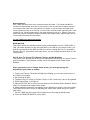
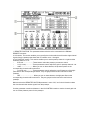
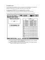
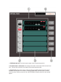
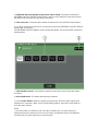
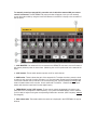
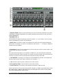
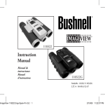
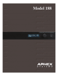
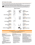
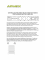
Network Settings
Each 1788A and 188 must be set to a different device ID number. (The Yamaha AD8HR ID
numbers are automatically set by the console, but this is not the case with the Aphex preamps.)
Youʼll need to keep track of the units network ID numbers so you can assign the digital inputs
from the preamp properly in the console. You will need to have the proper digital I/O option cards
installed in your Yamaha digital mixer for the Aphex preamps to plug in to. Please consult your
Aphex and Yamaha manuals for detailed information about digital inputs, digital outputs, pinouts
for connectors and word clock information.
For the 1788A follow these instructions:
MODE BUTTON
This selects which port handles remote control communications for the 1788A: MIDI or
LAN. No matter whether you are using the MIDI or the LAN port for remote control, you
must first put the Mode into MIDI in order to be able to change the Set I.D. parameters.
Once the Set I.D. parameters have been stored, you can change the Mode back to LAN
if appropriate.
Set I.D. How To Change The Channel, Device, and Net Numbers
This button steps through the three key unit identification parameters of Channel, Device
and Net numbers. The presently in effect values will appear in the Global Status
Readout.
When you need to set or change these values, you must go through the
Adjust/Store procedure as follows.
1. Press Local Control. The button will light up indicating you now have local control of
the 1788Aʼs front panel.
2. Set the Mode to MIDI.
3. Toggle the Set I.D. button to Channel, Device or Net - whichever is due to be updated.
4. Press Adjust/Store. It will light up.
5. Spin the ADJUST dial to set the correct number in the General Status Readout. Select
other I.D.s as desired and adjust their values.
6. When the desired numbers are updated, press Adjust/Store again to store the update.
The Adjust/Store button will go off indicating the values were stored and youʼre back in
safe mode.
7. Put the 1788A into the correct remote interface port by using the Mode button.
8. Press the REMOTE WAKEUP on the 5200.
For the 188 follow these instructions:
Turn the encoder clockwise until you get to a screen that shows SYSTEM CONFIGURE.
In order to safeguard against unwanted changes to the system configuration, the rotary
encoder must be pressed in for several seconds. The system configuration includes
clock source, format and sample rate, display contrast, Net Number assign, DHCP/IP
select and system configure exit.
Net Number
The Net Number identifies the particular unit within a system. Note: There must be only
one unit assigned to one Net Number otherwise the Remote Control and metering will be
unpredictable.
DHCP/FIXED IP
DHCP requires a network router, which will ʻserveʼ an IP address dynamically. Fixed IP
forces the address that is programmed into the unit and modified by the Net Number.
The letter ʻDʼ will be in front of the IP address when DHCP is selected and the letter ʻFʼ
will be in front of the IP address when Fixed IP is selected. For our needs, this MUST be
set to DHCP.
CONNECTIONS
Connect CAT5 patch cables from all preamps to the 100 Base-T network switch (The
switch may not be required if your network router has enough inputs for all of your
preamps). Connect the 100 Base-T network switch to the 100 Base-T network router via
CAT5.
Connect the null modem cable from the Yamaha HA REMOTE output to the RS-422
input on the Aphex 5200. If you connect to a Yamaha PM5D or DM2000 set the [PC RS422]
switch next to the HA REMOTE connection to RS422.
Press the REMOTE WAKEUP on the 5200.
The following Aphex parameters cannot be adjusted from Yamaha digital mixers:
1. Pad on/off
2. Phase reverse on/off
3. MicLim on/off
4. Mute on/off
For DM1000 users:
The DM1000 can control the gain and phantom power settings on each channel of the 1788A and
188 when used with an Aphex 5200 LAN interface. The DM1000 can control up to four preamps
simultaneously.
Tip: You cannot store the Phantom power setting as a Scene on the DM1000. This section
describes how to connect and configure the DM1000 and two preamps.
Make sure the proper digital I/O cards are installed in the DM1000.
Press the DISPLAY ACCESS [SETUP] button repeatedly until the Setup Remote page appears.
(See image below)
1. REMOTE FUNCTION. This parameter selects a device to be connected to the DM1000
REMOTE connector.
2. HA section. This section enables you to specify the slot channels that will receive eight channel
signals from the preamps that have their ID numbers set to 1 through 4.
3. HA CONTROL section. This section enables you to set the preamp channel 1–8 gain and the
Phantom power on or off.
•
ID #1–#4........................These buttons select the preamps you want to control.
•
1–8 (1st row).................These parameter controls adjust the gain for preamp channels 1–8.
•
+48V .............................When you turn on these buttons, the phantom power on the
corresponding channels will be turned on.
•
1–8 (2nd row)............... These parameter controls adjust the cut-off frequency of the highpass filter for the corresponding channels. They are grayed out and cannot be set for these
preamps.
•
HPF ................................ When you turn on these buttons, the high-pass filter on the
corresponding channels will be turned on. They are grayed out and cannot be set for these
preamps.
Make sure that the REMOTE FUNCTION parameter is set to “HA,” and in the HA section select
the slot channels that receive signals from the preamps.
Use the parameter controls and buttons in the HA CONTROL section to set the channel gain and
turn on/off the phantom power for the preamps.
For DM2000 users:
You can control the parameters of up to 12 preamps from the DM2000 by connecting the
DM2000ʼs REMOTE port to the Aphex 5200 using a null modem cable.
Configuring the REMOTE Port & Assigning Slots to HA IDs
The REMOTE port can be configured, and Slots assigned to HA IDs as follows.
Use the DISPLAY ACCESS [SETUP] button to select the Remote Port Setup page.
1. Use the cursor buttons to select the REMOTE FUNCTION button, use the INC/DEC
buttons to select HA, then press [ENTER].
2. Use the cursor buttons to select the HA SLOT parameters, and use the Parameter
wheel or INC/DEC buttons to select the Slots.
1. Use the SELECTED CHANNEL PHASE/INSERT [DISPLAY] button to select the HA
Control page.
2. Use the cursor buttons to select the ID of the HA (preamp) that you want to control, and
then press [ENTER].
3. Use the rotary controls to set the gain of each HA channel, and use the +48V buttons to
turn phantom power on or off for each channel.
4. The HPF (high pass filter) cutoff frequency parameters cannot be used with Aphex
preamps. However, the HPF buttons will turn HPF on or off for each channel.
All parameter settings, excluding the phantom power on/off setting, will be saved as part of a
scene.
For M7CL users:
To set up an external HA, you will use the EXTERNAL HA popup window on the M7CL-32/48.
These popup windows are collectively referred to as the “EXTERNAL HA popup window.”
1. In the function access area, press the RACK button to access the VIRTUAL RACK window.
2. In the upper part of the VIRTUAL RACK window, press the EXTERNAL HA tab to display the
EXTERNAL HA field.
1. EXTERNAL HA field- This field shows the state of the connected external HA.
2. ID / Model name / +48V master This displays information for the external HA mounted in the
rack. This area also shows the on/off status of the master phantom power.
3. Virtual racks- There are six racks in which remotely controllable external HA units can be
mounted. If an external HA is mounted, its settings (GAIN setting, phantom power, and HPF
on/off) are shown. When you press a rack, the EXTERNAL HA popup window for that rack will
appear.
4. EXTERNAL HA PORT SELECT popup button (M7CL-32/48)- This button accesses the
EXTERNAL HA PORT SELECT popup window, where you can specify the input ports to which
the external HA mounted in the rack will be connected.
5. Field select tabs- Use these tabs to switch the field shown in the VIRTUAL RACK window.
6. In order to specify the input ports for an external HA, press the EXTERNAL HA PORT SELECT
popup button for that rack
The EXTERNAL HA PORT SELECT popup window will appear. The popup window includes the
following items:
1. PORT SELECT buttons- These buttons specify the input ports to which the external HA is
connected.
2. NO ASSIGN button- This button defeats the port selection.
3. Use the PORT SELECT buttons to specify the input ports to which the audio output of the
external HA is connected. When youʼve finished making settings, press the CLOSE button to
close the popup window.
NOTE
• If an external HA is connected to one of the M7CL-32/48ʼs slots, you must specify the
appropriate input port manually. If this is set incorrectly, the external HA will not be detected
correctly when you patch input ports to input channels.
To remotely control an external HA, press the rack in which the external HA you want to
control is mounted. The EXTERNAL HA popup window will appear. Here you can remotely
control the external HA by using the knobs and buttons in the M7CLʼs display or the encoders of
the top panel.
1. +48V MASTER- If an external HA is connected to the REMOTE connector, the on/off status of
the master phantom power is shown here. (Switching this on/off is performed on the external HA
itself.)
2. +48V buttons- These switch phantom power on/off for each channel.
3. GAIN knobs- These indicate the gain of the external HA. To adjust the value, press the knob
to select it, and use multi- function encoders 1–8. The level meter located at the immediate right
of the knob indicates the input level for the corresponding port. (Aphex preamps do not provide
level information back to the console. So this meter will not function. However the main input
meters will show the input level from the digital inputs.)
4. FREQUENCY knobs / HPF buttons- These controls switch the external HAʼs built-in highpass filter on/off, and adjust its cutoff frequency. If you press the FREQUENCY knob to select it,
youʼll be able to adjust it using the corresponding multifunction encoder. (HPF frequency cannot
be changed!)
5. Rack select tabs- These tabs switch the rack that is displayed in the EXTERNAL HA popup
window.
To remotely control the external HA from an input channel of the M7CL, use the
navigation keys to access the OVERVIEW screen that includes the channel whose HA you
want to control.
Press the HA/PHASE field of the channel whose external HA you want to adjust; the
HA/PATCH popup window will appear.
Press the input port popup button, and select the input port assigned to the external HA.
With these settings, the external HA can be used in the same way as the M7CLʼs own HA.
External HA settings are saved as part of the scene. However, the phantom master setting is an
exception to this.
For PM5D users:
HA (Head Amp) screen
In this screen you can make settings such as phantom power (+48V), gain, and HPF on/off settings for
each of the internal head amps or for each channel of an external head amp device like the Aphex
1788A and 188.
1. DISPLAY MODE- Select one of the following as the type of head amp displayed in the screen.
• INTERNAL HA (PM5D-RH/DSP5D) The internal head amp channels (AD IN 1–48, AD STIN 1–
4) will be displayed.
• EXTERNAL HA 1-4
• EXTERNAL HA 5-8
The channels of an external head amp device (ID number= 1–4, or ID number= 5–8) connected
via the [HA REMOTE] connector will be displayed.
2. Model name- For each ID number, this indicates the model name of the external head amp
device that is connected. If no device is connected this will indicate “-----”. The Aphex 1788A and
188 will show up as AD8HR.
3. Slot/Channel- Here you can view/select the slot and channels to which the audio output of the
external head amp device is connected.
Note
If an external head amp device is connected to a PM5D slot, you must specify the appropriate
slot/channels manually. Please note that if you specify an incorrect setting, the input channel HA
indication in screens such as the IN HA screen may differ from the actual state.
4. +48V MASTER- If a preamp is connected via the [HA REMOTE] connector, this indicates the
master phantom power on/off status. (Otherwise, this indicates “---”.)
5. +48V- Switches phantom power (+48V) on/off for each channel.
6. HPF (High Pass Filter)- Turns the HPF on/off for each channel.
7. Cutoff frequency- This feature is not available for the Aphex 1788A and 188.
Aphex hopes that you find this documents helpful, but again, we highly recommend that you read
the 1788A manual, 1788A RC manual and your Yamaha digital mixer manual for more details
and a solid understanding of each product.
You should always make sure your mixers and preamps have the most current firmware installed.