1
2-Series Integrated Wireless Control System
Crestron MC2W
Connectors, Controls & Indicators (Continued)
#
CONNECTORS1, CONTROLS &
INDICATORS
12
COMPUTER
COMPUTER
Pin 1
Pin 9
DESCRIPTION
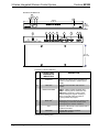
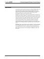
(1) DB9 female, RS-232 computer console port.
Connector is used when programming with a PC. The port is
modem compatible (modem and PC cables not included).
Supports baud rate of up to 115 kB. Use with a standard DB9
straight through cable. Pins 1, 4, 6 and 9 are not used but may
be connected.
PIN #
ABBREVIATION
DESCRIPTION
2
TXD
Transmit Data
3
RXD
Receive Data
5
SG
Signal Ground
7
CTS
Clear To Send
8
RTS
Request To Send
13
NET11, 12
Four-position terminal block connector for data and power.
Connects to Cresnet control network.
Pin 1 (24) Power
Pin 2 (Y) Data
Pin 3 (Z) Data
Pin 4 (G) Ground
Expandable via C2N-NPA8 Network Poll Accelerator10.
14
24 VDC11, 12, 13
(1) 2.1mm barrel DC power jack, 24 Volt DC power input;
(PW-2410RU power supply included);
Passes through to NET port to power Cresnet devices.
24VDC
1.0A
1.
2.
3.
4.
5.
6.
7.
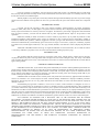
Interface connectors for NET, IR SERIAL OUT, INPUT, IR IN and RELAY OUT ports are provided with the unit.
This LED was labeled ERR on units manufactured prior to 2005. It is functionally the same; only the labeling has changed.
Transmission levels on the infrared – serial output connectors are in the 0 to +5 VDC range, which may not be compatible with all RS-232 devices.
A port can be used for either IR or RS-232 communications but not both.
Digital outputs are TTL values and may not work with devices requiring a “dry” contact closure (e.g. low voltage motor controllers).
Ports can be used for either input or output but not both.
The pinout of each 9-pin port is non-standard; it contains RS-422 pins in addition to RS-232. This may result in a conflict with some equipment
and therefore all nine pins should not be used. Only the required pins for each communication type should be connected. For RS-232 and –422,
pins 2, 3, 5, 7 and 8 are wired straight through.
8. Data Set Ready (DSR) and Data Terminal Ready (DTR) are not supported.
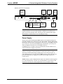
COM (DB9)
9. To support RS-485, tie pin 1 (RXD-) to pin 9 (TXD-)
RS-485 BUS
CONNECTOR
and pin 4 (TXD+) to pin 6 (RXD+) in the cable.
(Refer to table at right.)
Tie Pins 1 & 9
Tie Pins 4 & 6
+
Pin 5
G
10. The Cresnet Poll Accelerator effectively increases the network speed, fan-out and device addresses by a factor of 8 for each Poll Accelerator
added to the system.
11. The MC2W can be powered via the 24 VDC jack or the NET port. Be sure to use a Crestron approved power supply as another may cause
damage.
12. Use care in wiring installations to avoid applying 24 VDC to Cresnet wiring from an AC power pack as well as from a system device that contains
its own power supply. Although this condition should not cause any damage, Crestron does not recommend it. In those network configurations
that require more power than can be supplied by the primary power supply alone, disconnect the +24 VDC Cresnet wire from those devices that
will be powered by an AC power pack.
13. An optional power pack (PW-2420RU) provides 38 watts to Cresnet devices when connected to the MC2W.
6 • 2-Series Integrated Wireless Control System: MC2W
Operations Guide – DOC. 6143A