1
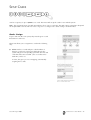
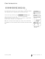
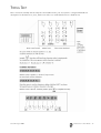
3GS Integrated Security Solution
3GS Version 5
User Guide
EUROPLEX TECHNOLOGIES
Company Web Site address: www.europlex.ie
Europlex Technologies [Ireland] Ltd.
Europlex Technologies [UK] Ltd.
Clonshaugh Business and Technology Park,
Clonshaugh, Dublin 17,
Ireland.
Tel: +353 - 1 - 2500500
Fax: +353 - 1 - 2500590
e-mail: [email protected]
Technical Support: e-mail [email protected]
Ground Floor, Trent House, University Way,
Cranfield Technology Park, Bedford MK43 0AN,
England.
Tel: +44 - 1234 - 757100
Fax: +44 - 845 - 3307240
e-mail: [email protected]
Technical Support: e-mail [email protected]
Warning
While this system is an advanced design integrated security system, it does not offer guaranteed protection
against burglary, fire or other emergency. Any alarm system, whether commercial or domestic, is subject to
compromise or failure to warn for a variety of reasons.
Therefore, good installation practices, thorough testing and regular maintenance by the installation company
and frequent testing by the user are essential to ensure continuous satisfactory operation of the system. It is
recommended that the installation company offer a maintenance program and instruct the user with the
correct procedure for use and testing of the system.
Disclaimer
Europlex make no representations or warranties with respect to the contents hereof and specifically disclaim
any implied warranties of merchantability or fitness for any particular purpose. Further Europlex reserve the
right to revise this publication and to make changes from time to time in the contents hereof without the
obligation of Europlex to notify any person of any such revision.
Copyright
Europlex Technologies [Ireland] Ltd. (hereafter referred to as Europlex) 2004. All rights reserved. No part of
this publication may be reproduced, transmitted, stored in a retrieval system, or translated into any language
or computer language in any form or by any means electronic, mechanical, magnetic, optical, chemical,
manual or otherwise without the prior written permission of Europlex.
All products or services mentioned in this manual are covered by the trademarks, service marks or product
names as designated by the companies who market those products.
3GS Version 5 User Guide - Issue 4, Manual Code 6086, August 2004.
3GS VERSION 5 USER GUIDE
CONTENTS
■
Introduction.................................................5
■
3GS System Keypad/Display ........................ 6
■
Menu options .............................................. 7
■
Navigating the Help Menu........................... 8
■
Unset/Reset .................................................9
■
Enable/Disable Engineer............................10
■
View System Status ....................................10
■
Over-ride Faults ........................................10
■
Part Set/Unset Individual Area ...................11
■
Half Set/Set Individual Area .......................12
■
Full Set ......................................................13
■
Unable to Set ............................................ 14
■
Setting an Individual Area..........................15
■
Unsetting an Individual area ...................... 16
■
Coded Reset .............................................. 17
■
Set Date & Time......................................... 18
■
Change your own ID.................................. 19
■
User Setup ................................................ 20
■
Area Setup ................................................ 23
■
Radio PA Assign ......................................... 24
■
System Logs...............................................26
■
Radio PA Test .............................................27
■
3GS Access Control ...................................28
■
Setup Cards...............................................29
■
Passing and Voiding Cards......................... 31
■
Card Information....................................... 33
■
Manual Door Control.................................34
■
Hour Adjust ...............................................35
■
Edit Time Commands.................................36
■
Accept all Alerts......................................... 37
■
Inhibit Zones/Doors ...................................39
■
Program ACE .............................................40
■
User Option Assignments........................... 43
■
Area Descriptions ......................................44
■
User Area Assignments .............................. 45
■
Typing Text.................................................47
INTRODUCTION
This manual is intended as a quick reference User Guide for the 3GS System. This manual was designed for use with
the Europlex 3GS Version 5 Integrated Security Alarm System. It explains how to arm and disarm the system and details
all user functionality.
Note In compliance with EN50131-1:1997 and EN50131-6:1998, all codes are now 6 digits in length.
User Menu
The User Menu, by which the user programs the system, is accessed via the keypad by keying in your 6 digit User Code
– which is unique to each user – plus the option key Help. This will allow you to choose one of the menu options
available.
Display
The 3GS system has a two line by 24 character LCD display e.g.
When you are navigating through the Help menu:
●
The first line shows the option
●
The second line shows how to directly select the option without using the Help function.
Alert Messages
When in normal operation, the system will display the day, date and time on the first line of the display. The second
line will flash any recent system events or information (such as a fault with one of the fuses or battery, or an alarm
condition).
If the condition continues, e.g. Battery Problem, the message displays steadily instead of flashing. This message will
continue to display until you remove the message [See page 37: Accept all Alerts].
If the system is in Full Set/Full Arm mode [See page 13: Full Set], there is no alert message indication on the display, the
bells will trigger as required and the system dials out.
Pressing 001020 SHIFT SHIFT PART will give information on the areas/zones affected.
These messages can be removed from the display (and the buzzer silenced) using the Alert Accept procedure.
Keypad Private Mode
The 3GS is designed to allow only one user at a time to operate the system.
If the display shows:
when you attempt to use the keypad, this means that a user is
operating the system at another keypad. Wait until the system is free before attempting to use the keypad again.
Alarm Duress Code
3GS has an in-built Alarm Duress Code feature, which allow you to trigger a silent Duress alarm by simply keying in the
first 5 digits of your code, and then the sixth digit plus 1. For example, if your code is 001234, then by keying in
001235 you will trigger a Duress alarm, which will not display on the panel and will not sound an alarm, but will send
a trigger directly to your central security station.
EN50131-1:1997
●
The 3GS system is Security Grade 3 Environmental Class II compliant.
●
The 3GS system is also compatible with SEAP Class IV Systems.
Issue 04 August 2004
3GS Version 5 User Guide 5
3GS SYSTEM KEYPAD/DISPLAY
6
MENU OPTIONS
The system is programmed using the Help menu options. You can use
these menus to:
●
Disarm the system and reset all warning devices
●
Enable/disable User 1 (engineer)
●
Remove system display messages and silence the buzzer
●
Part set the system and Unset/Disarm an area
●
Half set the system and Set/Arm an area
●
Full set the system
●
Reset the system following an alarm
●
Set the system date and time
●
Change existing user codes
●
Set up new users
●
Set up a new area system
●
View system log
●
Adjust the system for summer/winter hour change (daylight saving
time)
●
Overide system faults on remote/timed FULL SET.
●
Isolate a troublesome zone that is, for example, preventing the
system from arming
All of these options are accessed by entering your 6 digit CODE
followed by the HELP key.
Your installer will have configured your own unique 6 digit CODE,
which will allow you to display and scroll through the options available
to you.
An option is selected by pressing the YES key
.
Use the UNSET key to move to the next option
Use the PART key to move back
To exit without selecting an option, use the NO key
Note Only options which have been assigned to a user are displayed.
The Master user will have all options.
Note Once the help routine is entered, a selection must be made within
90 seconds, otherwise the system will exit from this menu.
Note The hash button
Issue 04 August 2004
acts as an ENTER key for the keypad.
3GS Version 5 User Guide 7
NAVIGATING THE HELP MENU
To navigate the Help menu options use the UNSET, PART, YES, NO,
Their functions are explained below.
8
keys.
UNSET/RESET
Unsetting/Disarming the System
Select the Unset/Reset option to disarm the system when you enter the
premises, or to cancel alarms, bells etc. after an alarm activation.
This will put the 3GS into Unset/Disarm mode (i.e. normal daytime
operation). The system alarm outputs (buzzers etc.) which had been
activated are reset to normal.
After an Alarm Activation
After an alarm activation proceed directly to the control panel enter the
code and press Unset.
The display will show:
Followed by:
followed by the cause of the alarm, i.e. which zone has been opened.
Example:
Alarm alert message:
Zone alert message:
These messages will be flashing.
To clear flashing (Alert) messages follow "Accept All Alerts"
Issue 04 August 2004
3GS Version 5 User Guide 9
ENABLE/DISABLE ENGINEER
Using this option, the system can be configured to enable/
disable the engineer code for EN50131-1:1997.
This allows the user to control when the engineer has access to the alarm pad. When the engineer is finished on site,
the user should always disable the engineer code.
Enable/Disable Engineer code.
Enter user code 001020 SHIFT #
Enter user code 001020 SHIFT #
Note This menu option applies to Class IV systems and all software that supersedes 3GS version 5.50.
VIEW SYSTEM STATUS
This option displays the current
status of all zones and areas in the
system.
All open zones or set areas will be displayed when this option is selected.
OVER-RIDE FAULTS
If there is a fault condition on the system – such as a mains fault – this flashes on the display. Users won’t be able to set
the system while there is a fault condition on the system. The user may, however, over-ride this fault condition and set
the system.
If users try to set the system when a fault condition is registered, a NOT SELECTED message is displayed and the system
fails to set. In such cases, users must select the OVER-RIDE FAULTS option. Doing this inhibits the registered fault
condition(s), allowing users to go ahead and set the system.
Note Not all fault conditions can be over-ridden. All fault or tamper conditions that are disabled with a "Call Service"
message require an engineer reset before the system can be set.
10
PART SET/UNSET INDIVIDUAL AREA
Your system will be set up as either:
●
a standard alarm system with one alarm area, or
●
a multi-area system, with up to 30 separate alarm areas
within one.
A standard alarm system is set/armed using the Part, Half, and
Full procedures.
The Part and Half keys are used to unset/disarm and set/arm
individual areas within the multi-area system.
Part Set
With a standard alarm system, you can isolate particular areas
of the premises and set/arm these areas independently of the
rest of the system.
Part Set allows you to protect the perimeter of a premises
while allowing free movement through the exit and access area
(e.g. from door, hall).
This would typically apply to the day or evening operation of
the system when people are on the premises and using the
common exit. There is free access to the areas being used while
the rest of the building is armed.
There are no entry or exit times associated with this mode and
protection is applied instantly.
The display remains blank and will only change to show alert and warning messages.
If selected while entering the building while the entry timer is running, the entry mode is cancelled and the buzzer is
silenced.
●
If selected by mistake refer to “Unset/Reset”.
●
If unable to set/arm refer to “Unable to Set”.
Issue 04 August 2004
3GS Version 5 User Guide 11
HALF SET/SET INDIVIDUAL AREA
HALF Set is used to provide full perimeter protection
(including exits) when people are on the premises and all exits
are locked, i.e. late working operation.
This mode immediately arms the perimeter and the Exit zones,
i.e. no exit timer applies.
If selected when entering the building, the entry mode is
cancelled and the buzzer is silenced.
●
If selected by mistake, see Unset/Reset on page 9.
●
If unable to set/arm, see Unable to Set on page 14.
12
FULL SET
This option will set/arm the entire system. Ensure that all zones
(doors, windows, etc.) which are not on the exit/entry route
are closed.
Exit Sequence
Enter your user code and press FULL. Leave via the exit route.
The buzzer will stop at the end of the exit time and the system
will fully set/arm.
The buzzer will sound during the exit routine. At the end of
the exit time, if all zones are closed, the buzzer will stop. The
system will then become Fully Set/Armed if:
햲 the exit time expires, or
햳 the ‘exit terminator’ button is pressed.
If a zone is still open, the system will wait indefinitely for a
clear condition, then set/arm when the zone is closed.
During the exit period the buzzer will sound with one of two
possible tones, a long beep indicates that all zones are closed
and that the system will set/arm correctly when the exit time
expires; a short beep indicates that one or more zones are
open and the system will not SET/ARM until all these zones
have closed.
Multi-Area system configuration
In a multi-area system, Full Set has the effect of setting/arming
all areas plus the Common Area.
Alarm on exit
If the user strays from the exit route, a local alarm will be
generated, tripping internal bells. The system will dial out after
the local indicator has operated for 30 seconds. This is to allow
the user to clear false alarms.
Action to take:
●
Return to control panel.
●
Select ‘UNSET’ [See page 9: Unset/Reset].
●
Remove alert messages [See page 37: Accept all Alerts].
●
Reselect “Full Set” [See page 13: Full Set] and exit the
premises.
Entry Sequence
When you enter the building, the system will be Fully Set/Armed. The entry buzzer sounds and the entry timer begins.
This gives you a specific number of seconds in which to go to the keypad and Unset/Disarm the system. Otherwise a
full alarm is generated along with the alert message CODE ENTRY TIMEOUT. In this case repeat the Unset/Disarm
procedure to silence the alarm.
Issue 04 August 2004
3GS Version 5 User Guide 13
UNABLE TO SET
If attempts to Part, Half, Area or Full Set the system fail, the system buzzer briefly sounds and the display briefly shows:
This is normally due to a zone or door being open away from the exit route.
The 3GS system will display a FAILED TO SET message followed by suggestions as to what action to take in order to set
the system – for example, close all zones/doors.
Note The system will display which zones are open. In a multi-area system, the display does not indicate which
zones are open until you press CODE SHIFT SHIFT PART.
For example:
Action to take:
●
Go to the Area concerned and close the zone(s).
●
Return to the keypad and reselect the required ‘set/arm’ mode.
●
Leave via the exit route.
The system buzzer will stop when:
1. The Exit time expires or
2. When the ‘exit terminator’ button is pressed (if fitted).
14
SETTING AN INDIVIDUAL AREA
In a Multi-Area system, the whole premises may be divided into up to 30 separate alarm areas, which can be set/armed
and unset/disarmed independently of each other.
Note From Standard 3GS Software v5.80 onwards, all systems have 30 alarm areas. For previous versions, please
reference the relevant documentation.
Note Please ensure that the Master User has given you the Part/Area Unset and Half/Area Set options, and that the areas
have been assigned to you [See page 37: Accept all Alerts].
Setting an area
The installer or Master User will tell you which areas have been assigned to you, and you will be able to set/arm or
unset/disarm these areas only.
To set/arm an area, key in your Code plus HALF.
The display will prompt you to set/arm the area you are now leaving
Press
Press
or
to set/arm this area.
to abort the procedure.
The display will show
the exit buzzer begins and you can now leave the area.
Multi-Area Setting
Please consult your installer on setting more than one area.
Issue 04 August 2004
3GS Version 5 User Guide 15
UNSETTING AN INDIVIDUAL AREA
Unsetting/Disarming an area
Unsetting/disarming areas is similar to setting/arming areas, except that the PART key is used. You will be able to unset/
disarm only those areas that have been assigned to you.
Key in your Code plus PART.
The display will give you the option to unset/disarm the area:
To unset/disarm area 1, press
Press
or
to abort the procedure.
The display will show
followed by
Note Please ensure that the Master User has given you the Part/Area Unset and Half/Area Set options, and that the areas
have been assigned to you – see User Setup on page 20 and see Area Setup on page 23.
Areas and Full Set
The Full Set option operates in an multi-area system in the same way as in a standard alarm system. Keying in your
code plus FULL will arm all areas and begin the exit timer.
Note To Full Set the system (all areas), you must be assigned the option by the Master User.
Common Area
The Multi-Area system consists of up to 30 Alarm areas plus a Common Area (usually the entrance/exit lobby or front
door).
The Common Area sets/arms and unsets/disarms automatically:
●
When all the other areas are set/armed, the Common Area automatically sets/arms.
●
When one area is unset/disarmed, the Common Area automatically unsets/disarms.
Note From Standard 3GS Software version 5.80 onwards, all systems have 30 alarm areas. For previous versions,
please reference the relevant documentation.
16
CODED RESET
Under normal conditions, the system can only be re-armed (after an alarm activation) following a service/installation
company visit.
When an alarm has occurred the display will show a CALL SERVICE message and the user will not be able to re-arm the
system.
When enabled, the Coded Reset option allows you to re-arm the system, avoiding the need to call an installer to the
site.
When you have acknowledged an alarm, the keypad will continue to display the message:
If you attempt to re-arm the system, the keypad will beep, and then briefly display the message:
You should now contact the Security Control Station for a release code. If the Security Control Station is unable to give
you a release code, contact your installer.
User Reset Procedure
Select Coded Reset.
The display will show a random 4-digit number for standard system and a 6-digit
number for Class IV.
Contact the Control Security Station with this random number.
The Central Station operator then converts this number to a 4-digit (6 digit) return code acceptable to the system.
When you receive your return code from the Central Station operator, return to the keypad, and press the
key.
The display will prompt you to enter the return code:
Key it in at the prompt. If the code is incorrect, the display will show:
When you have keyed in the correct code, the display will show:
You can now re-arm the system by selecting Full Set.
Note All users who have the FULL SET option will automatically be assigned the Coded Reset option [See page
20: User Setup].
Issue 04 August 2004
3GS Version 5 User Guide 17
SET DATE & TIME
The time is set in 24-hour clock notation.
To adjust the time for the Summer/Winter hour
change (Daylight Saving Time) – see Hour Adjust
on page 35.
18
CHANGE YOUR OWN ID
This option allows the user to change the
ID code normally assigned to them by the
Master User.
When the option is selected, the user is
prompted to enter a new 6 digit code. To
avoid duplicate codes, a second choice
of code is requested.
Once both codes have been entered the
system will either reject or accept the
user’s choice. If rejected the user must
repeat the procedure and enter two new
codes. If accepted, the system will assign
one of them (chosen at random) and will
indicate which code is to be used.
This option is cancelled after use so each
user has only one opportunity to
change their own code. The Master user
may, of course, grant the option again if
required. Once chosen the code is
completely private.
Remember the two codes you have
entered! The one chosen by the system
as your new code will be indicated by
either ‘1’ or ‘2’.
Once changed, test your code to ensure
that the system has accepted it. In not,
consult your Master User or installer.
Issue 04 August 2004
3GS Version 5 User Guide 19
USER SETUP
This menu is used to set up new users on the system, entering their names and assigning
ID codes and options.
Changing User ID Codes
This option allows the Master User (user 2) to change individual ID codes for all
other system users (1 - 250).
Note User ID codes must be 6 digits in length.
The new ID code is accepted and functioning as soon as you enter it.
Press
at the user number prompt to exit the ID codes menu
when finished.
You should now give the user the required options.
20
Changing User Options:
The Master User can assign the following menu options to all users. Some
options are linked to other functions, so that assigning an option to a user may
automatically give the user other options as well.
●
Unset/Reset
●
Part Set / Area Unset/Disarm
●
Half Set / Area Set/Arm
●
Full Set (also Coded Reset)
●
Set Date/Time
●
Change ID
●
User Setup (also Setup Areas and Radio PA Assign)
●
System Log (also Test Radio PA, Setup Cards, Card Information and
Manual Door Control)
●
Hour Adjust (also Accept All Alerts)
●
Edit Time Commands
●
Inhibit Mode
Any user can be assigned some or all of these options. The Master User has all
of these options by default.
Note By default, User 1 is the installer and User 2 is the Master User.
Note The User Options menu also features Mode 5/6/7/8/9 options. These
options are for installer use only and cannot be accessed.
Issue 04 August 2004
3GS Version 5 User Guide 21
Changing User Names
This feature is used to enter individual user names into the system.
Text is entered via the keypad using the procedure described in Typing Text, but it
is recommended that this be carried out by the installer.
22
AREA SETUP
The Area Setup menu allows a Master User to assign areas to the system users (1 to
250).
Note The option to set/arm or unset/disarm an area is configured by the
Master User in the User Setup menu.
The number of areas to be used in the system is configured by the installer, – the
Master User assigns areas to users.
Note User descriptions and PIN codes are set up in the User Setup menu.
The system currently allows for up to 30 areas. The Master User enters the number
of the user to whom the area is to be assigned, and then scrolls through each area
in turn, assigning or denying that area to that user.
Note From Standard 3GS Software v5.80 onwards, all systems have 30 alarm
areas. For previous versions, please reference the relevant documentation.
Note To be able to set/arm or unset/disarm an area, the user must be given:
the Part/Area Unset and Half/Area Set options,
and the Set and Unset option for that area,
using the User Setup menu.
Issue 04 August 2004
3GS Version 5 User Guide 23
RADIO PA ASSIGN
3GS allows for up to 126 3-button Radio Hold-Up handsets. This option is used to setup Radio PA (RPA) units for use
on a 3GS system. Each RPA unit must be given a system ID number and a description (optional), and can be assigned
up to five different functions, for example, SUSPICION, RAID etc.
Adding a new RPA to the system
When you key in your code plus SHIFT SHIFT *, the display will show:
Press UNSET to enter the RPAs menu. The display will show:
In this example we will add RPA 3 to the system, so use the UNSET key to scroll forward until the display shows:
Now press any button on the RPA
The display will now show:
where the 10 digit number is the serial number encoded into the unit at the factory. This unit has now been entered
into the system as RPA 3. Press NO to return to the RPA menu.
Giving the RPA unit a Description
At the prompt
press the
key to enter the Descriptions menu.
The display will show
followed by:
Key in the number of the unit to which you want to give a description (e.g. 3) and press the
24
key.
The display will show:
The first character will be flashing, and you can now enter a
description.
When finished, press the
key, ensuring that the cursor is in the vertical position as described in Typing Text.
Setting the RPA Options
The RPA unit has no options assigned by default, and so must be set up for use with the Radio HUA system. The unit
can be assigned five different functions:
●
RAID
●
DELAYED RAID
●
RAID CANCEL
●
SUSPICION
●
PHOTO ENTRY
Each function will be explained by the installer and is activated by pressing a combination of the three buttons on the
unit. The button combinations are also set up by the installer and will be explained by him.
To assign options to the RPA Unit, press
to enter the Options menu.
The display will show:
Enter the number of the RPA unit to which you want to assign options e.g. RPA 3, which now has the description
‘Security 1’.
The display will show
Assign the RAID option to this unit by pressing YES.
Use the NO key to deny the option and the UNSET key to move to the next option.
When finished assigning options, press the
key to return you to the main RPA
Number prompt.
To return to the main menu, press
When you press NO, again, you will be prompted
If
you have a printer connected to the 3GS controller you can now print off the RPA options you have just configured.
Press
to exit the menu and return to the normal display.
Issue 04 August 2004
3GS Version 5 User Guide 25
SYSTEM LOGS
The 3GS alarm log is a record of all system activity
(keypad input, status alerts, alarm activations etc.)
and this may be viewed or printed if a hard-copy is
required. The detail and length of the log provides an
invaluable record of the system operation for both
fault finding and alarm analysis.
The alarm log is 1000 events long (the Access Log is
3000 events) and each event is detailed with exact
date and time to the nearest second. System events
are displayed chronologically with the most recent
events appearing first.
The alarm log gives details of each event, which
appears on the display in sequence:
●
the date and time of the event;
●
the user name or zone number (e.g. Master
User);
●
the user number or zone description (e.g. User 2
Selected);
●
and the action taken (e.g. System Log)
●
Only 3 events are logged from a single source
when the system is set. All subsequent events are
ignored.
Alarm and Access Logs
3GS has two types of log: the standard Alarm Log,
which displays all the system events; and the Access
Log, which displays only Access Control-related
events, such as Invalid Card Entry, Door Forced, and
Time Zone Setup. The Access Log can also be viewed
using 3GS+ Access Management Software Package.
Printing the Alarm and Access Logs
When the option "PRINT LOG?" is displayed, if a
serial printer is connected and the serial port
correctly configured, a print-out of the log can be generated by selecting the YES key. Otherwise, any other key should
be pressed and the log will be displayed.
Viewing the Alarm and Access Logs
The log display can be stepped through quickly one line at a time by pressing the
key. The "*" appears in the
centre of the date & time display to make the log easily differentiable from the Stand-by/Unset/Disarm mode display.
The date and time remain visible in the display until all information regarding that particular event has been shown.
The PART SET key will ‘rewind’ one entry at a time to the first entry of the date currently being displayed, the UNSET
key will skip to the next entry. To leave the system log at any point in the record, press the NO key.
26
RADIO PA TEST
This option allows you to test each RPA unit in turn to ensure that the functions are correctly configured.
The system buzzer will sound intermittently to indicate that the test is in progress.
The display will show
followed by
Your installer will give a list of the button combinations for each option. When you press a button or combination of
buttons, the display will show the option assigned to that button and the field strength of the signal.
For example, if RAID has been assigned to the right (green) button, press this button. The display will show:
If the right (green) button has not been assigned to this function, the display will show
indicating the button that you have just pressed.
Note Some units may not show the percentage value.
Using the list given to you by the installer, go through each option in turn, ensuring that the right button combination
gives you the right option.
When finished, press
Press
to exit. The display will prompt:
to confirm.
When the RPA battery is low..
When the RPA battery level is low, the test information will not appear on the display.
Instead, the display will show
Replace the battery.
Issue 04 August 2004
3GS Version 5 User Guide 27
3GS ACCESS CONTROL
3GS can control up to 64 doors with internal and external readers, and 10,000 cards/tokens per system.
Access Control Readers
A variety of reader types are supported:
PIN code, magnetic stripe cards, proximity cards, ‘hands-free’ cards or a combination of card and PIN
code.
LED displays
Card readers may display a variety of LED indications:
Setting the system using access cards
3GS allows for cards to control setting/arming and unsetting/disarming of the complete alarm
system, or parts of it (i.e. areas). Please consult your 3GS installer for details.
●
Unset/Disarm inside the door: If the area is set/armed, then when a card with this
function is presented to the entry reader, the user is granted access to the door. When the
door is opened it will start the entry timer. This allows the cardholder to unset/disarm the
system by presenting the card to the exit reader.
●
Unset/Disarm outside the door: If the area is set/armed, then when a card with this function is swiped on the
entry reader, the user is granted access to the door. When the door is opened it will unset/disarm the system or
area immediately.
●
Set: If the area is unset/disarmed, then the cardholder can set/arm the area/system by presenting the card to the
exit reader and then presenting it to the entry reader during the FUNCTON ENABLE TIME. Alternatively the
cardholder can use the SET button to set/arm the area/system after pressing the card to the exit reader.
Note Please consult with your installer before operating these functions
Asset Protection
3GS Access Control can also be configured to protect assets (such as PCs). By locating tokens placed inside the asset,
and fitting ‘hands-free’ readers at doors. 3GS can be set up to report the illegal removal of the assets. Please consult
your installer for details.
3GS allows for visitor cards, holidays, a multitude of access levels, anti-passback, car park control, roll call of building
occupants and much more. Consult your 3GS installer for more details.
28
SETUP CARDS
3GS has a capacity of up to 10,000 access cards. This menu will set up the cards for use with the system.
Note The 3GS panel menus for cards are similar to those of 3GS+ Software. The card settings entered into the panel
can be uploaded to the PC and vice versa. Using 3GS+ to change access cards settings is recommended.
Cards.. Assign
To pass cards into the 3GS system, they must be given a card
ID between 1 and 9999.
This menu allows you to assign IDs to cards in the following
way:
●
Select. Batches of cards with pre-coded numbers of
between 1 and 9999 can be passed directly into the
system and given corresponding system IDs. The first card
of the batch becomes Card ID 1, the second becomes
Card ID 2, and so on.
In effect, this gives you 1-to-1 mapping, automatically
assigning IDs to cards.
Issue 04 August 2004
3GS Version 5 User Guide 29
Cards.. Options
The Options menu is used to assign a PIN code to one or a range of cards, and to restore the settings of cards that have
been deleted from the system.
When an invalid PIN code has been entered three times, the card to which the code is attached will be deleted from
the system.
The Restore menu will restore this card to the system without the need to set the card up again.
See the menu below.
30
PASSING AND VOIDING CARDS
Once a Card ID has been assigned, the card can then be passed into the system.
Card Range
Enter the range of cards to be passed, from 1 to 9999. To pass a single card, enter the
card number and press the
key twice.
Once the card(s) has been passed, you will be prompted for the Access level for this/
these cards.
Change Access Level?
An Access level is a combination of a limited time period and a group of doors, so that
once applied to a card, it will limit the card user to having access to certain doors at
certain times only. Up to 250 Access levels are programmed by the installer, who will
indicate which levels should be assigned to which cards. When you have assigned an
Access level, you are prompted for the Visitor Level.
Change Visitor Level?
The Visitor Level is used to program temporary cards, which will only be valid for a certain period of time (between a
given Start Date and End Date). The system allows for up to 250 different Visitor levels, which are programmed by the
installer. Once assigned, you are then prompted for a Function level.
Change Function Level?
Function levels give the user the ability to set/arm and unset/disarm an Area by presenting a card to a reader outside
the Area entrance door. A Function level will give a card 3 extra capabilities: to unset/disarm an area from the outside,
to unset/disarm an area from inside, and to set/arm an area once you have left (by swiping your card at a reader near
the exit door). Up to 250 Function levels are programmed by the installer. When you have assigned a function level,
you are prompted to change the PIN code requirement for the card.
Note Please consult your installer on the correct procedure for setting/arming or unsetting/disarming the system
using your card.
Issue 04 August 2004
3GS Version 5 User Guide 31
Change Requirement
This option allows you to decide if a card should also require a PIN code before it will grant access through a door. It
also allows you to change the existing PIN code for the card or create a new one.
Note The user should be aware that the PIN code created using this option will apply to all the cards being passed
at this stage
Once a PIN code requirement has been assigned, you will be prompted to identify the card location.
Change Card Location?
When passing the card, you must establish where the card actually is at the time of passing. The Roll Call and AntiPassback functions allow the installer to identify which cards are in use in the system at any given time, and to control
the use of cards within the system. This menu will identify the card as being inside or outside the alarm area when
passed. When all the system cards can be located at any time, they can be tracked and controlled effectively. When
you have assigned the card a location status, press the
key to return to the main menu.
Voiding Cards
The Void Cards option is used when you have a set of cards that you want to be removed
from the system.
Voiding a card removes all the card’s settings from the system, from system ID to access/
function/visitor levels.
Exiting the Setup Cards menu
Press NO to exit the Setup Cards menu.
The display will show:
If you have a printer connected to the controller serial port, you can now print out the
card settings you have just configured.
Press YES to print and NO to exit the menu.
32
CARD INFORMATION
The Card Information menu allows you to test the validity of a card and check that the
card settings that you have configured have been entered into the system.
Select the menu option. When the prompt
appears,
swipe the card or present it to the reader.
The display will then give details of the card ID, site code (which is configured by the
installer) and door at which the card is being presented.
Note When a card is presented, the display may not always show the card number.
If the display does not show any information about the card, present the card to the reader
again.
Issue 04 August 2004
3GS Version 5 User Guide 33
MANUAL DOOR CONTROL
The Manual Door Control feature gives
the user a manual over-ride on all system
door settings.
At any stage, the user can use this menu to
open/lock a door or series of doors.
Once you have selected your doors, the
system will check for Lock/Open Inhibits
operating on these doors. If none have
been set, the doors can be opened/locked
via the keypad.
The Open menu allows you to open a
range of doors permanently - i.e. the door
will remain open until you manually restore
the original door settings, or momentarily you can open one door for the number of
seconds for which the door lock would
normally remain open once access has
been granted.
When you select Permanent, you are
prompted to enter the range of door
numbers you wish to open. Enter the From
and To ranges. When the Permanent
condition is set on a door, the green LED
(access granted) on the node will flash. This
allows free access through the doors
selected until restored or locked.
The Momentary sub-menu will ask you for the number of the door you wish to open momentarily. Again, enter the
number. The green LED will light steadily while access is granted.
Restore restores all door settings to their defaults. Enter the range of doors to be restored and press
to accept
and quit. Once defaults have been restored, the system is in normal operation and no LEDs are lit.
The Lock menu works similarly to Open. When the Lock is manually set on a door, the card reader attached to the
door will not read or accept any cards. When the door is locked in this way, the red LED flashes to indicate access
denied.
34
HOUR ADJUST
This option adjusts the system clock to automatically take account
of the Summer / Winter time change (Daylight Saving Time).
It must be selected during the week prior to the Sunday on which
the hour change is to occur at 2.00am.
A warning message is displayed until the function is executed “Hour Change Sunday”.
The system will automatically set the hour forward or back as
appropriate.
The option toggles on and off – you cancel the hour change by
selecting it again.
Note Hour Adjust should only be selected during March/April and
October.
Issue 04 August 2004
3GS Version 5 User Guide 35
EDIT TIME COMMANDS
An automatic time command is a programmed command string which instructs the
3GS to execute a function at a pre-set time. For example, the system could be
instructed to automatically Full set the premises at 18:00.
Certain time commands are for installer use only, as indicated below. The other
commands are for Master User use.
This mode is a simplified "time command edit" function which allows the Master
User to modify the TIME at which the action will occur without allowing alteration
of the command.
The new time must be valid (24-hour format) or the procedure will not continue.
Note Enter "24:00" hrs to disable a time command.
After adjustment is made the
key should be pressed to program the new
time into the system.
Movement forward and backward through the time strings is provided by the
UNSET and PART keys.
SUNDAY HOUR
Checks for Hour change on Sundays. Installer user only.
LOG DUMP
Sets dial-out variable for system to dial a remote PC/Printer. Installer user only.
AREA 1 10M WARN to AREA 8 10M WARN
Automatic arming commands for Areas 1 to 8.
These commands (one for each block) start a 10-minute warning time (to inform
people that they must leave the building) after which time the relevant area will
arm.
BATTERY TEST
This command sets a time (1 per day) at which an automatic battery test will be
carried out. Installer user only.
FULL SET 10M WARN
Automatic arming command for the full system. Works in the same way as the Area
10-minute Warning but in this case the full system will arm.
Late working time commands
These commands allow for late working on the premises. They will arm the system/
area if the first arming time command is cancelled. These are:
L.W. AREA1 WARN to L.W. AREA32 WARN
L.W. FULL SET WARN
E.g. AREA1 10M WARN may be set to 7pm and the L.W. AREA1 WARN set to
9pm. Normally the first time command would arm the area 1 at 7pm. However, if
the user cancels the first time command in order so that he/she may work late then
the first time command is ignored and the system will be armed by the second
time command at 9pm.
SIA TEST CALL
Sets a communication parameter. Installer use only.
36
ACCEPT ALL ALERTS
Alert messages are flashing messages displayed to alert the user that a
particular condition exists/existed on the system.
Accepting the alert will remove the message and silence the buzzer. When
the Alert accept option is selected, all alert messages which are currently
displayed are accepted (removed).
If the condition that caused the alert message still exists, a steady warning
message will remain on the display until the condition indicated no longer
exists.
ALERT ACCEPT is logged along with the identity of the user.
In the event that an alert message is accompanied by a call service message,
to reset the system, an engineer is required on site to clear the alerts and
check the system.
Issue 04 August 2004
3GS Version 5 User Guide 37
Some examples of Alert Messages
38
INHIBIT ZONES/DOORS
This option is used for temporarily isolating troublesome zones (doors, windows,
movement detectors, etc.) which may be preventing the system from setting.
Zones/doors may be inhibited singly or in blocks.
Note The problem zone/door will be indicated on the display, e.g. Zone 3 Tamper,
Door 4 Open. Inhibit Mode provides two identical sub-menus, for zones and doors.
Use the appropriate sub-menu to implement the inhibit.
If zones/doors have been inhibited, on selection of FULL set mode, a message
will indicate how many are inhibited.
Selection of this option is logged by the system and an asterisk appears beside
the log entry to indicate the zone has been inhibited manually (zone may also
be inhibited via literal commands). The identity of the user to select the option
is also logged.
Operation
Having entered the user CODE and then pressed the NO key, the display will
read "INHIBIT FROM 1". Enter the number of the first zone to be inhibited
followed by
. The next displayed message is "INHIBIT TO 1".
Enter the number of the last zone in the block to be inhibited. This will be the
same as the first zone if only one zone is required. After the second parameter
has been entered the display will show "n INHIBITS" where n is the number of
zones/doors inhibited) and the buzzer will sound briefly before returning to
UNSET mode displaying the date and time.
The INHIBIT function can be re-entered any number of times to inhibit more
zones/doors, existing inhibited zones/doors will not be affected.
Clear Inhibits
To clear inhibits, re-enter Inhibit Mode using the engineer code followed by the
NO key. The message "CLEAR ALL INHIBITS?" will appear in the display. Press
YES to clear the inhibited zones. Press NO to inhibit more zones or to view
those zones which are already inhibited.
Issue 04 August 2004
3GS Version 5 User Guide 39
PORTABLE ACE
Some models of the 3GS keypad are supplied with an in-built reader which can be used in place of the 6 digit user
code to set and unset the system. This reader is called an ACE (Ancillary Control Equipment) reader and the card/
token/keypad is called a portable ACE.
Program ACE
The Europlex 3GS Portable ACE RKD consists of universal proximity read head assembly incorporated seamlessly
within a standard 3GS RKD node.
The 3GS RKD responds to proximity cards/devices when programmed to do so in an identical way to the programmed
user entering his access code. In this way, user rights programmed as a standard 3GS feature are maintained as is the
identification of the user in the 3GS database and system log.
The 3GS Portable ACE RKD is only compatible with the latest EN50131-1:1997 3GS software versions released from
March 2004 onwards.
The 3GS Portable ACE RKD is also compatible with the latest release of DD243, which is incorporated in the latest
EN50131-1:1997 3GS (version 5.7 or later). To ensure full DD243 compliance, a new DISABLE KEYPAD variable has
been created which disables the RKD keys of all System RKD nodes when the Portable ACE is used as an entry method
for DD243: 2002 compliance. See the 3GS Application Guides for more information.
Functions
The following functions are automatically ascribed to a Portable ACE cardholder:
Function No.
Description
1
UNSET
2
PART SET/AREA UNSET
3
HALF SET/AREA SET
4
FULL SET
5
SPARE
6
BELL ON
7
BELL OFF
8
SPARE
9
SPARE
10
SPARE
Programming the Portable ACE User
Before programming can commence, the new Portable ACE RKD Node must be installed on the 3GS Ringnet correctly
and the keys tested for correct operation. On the Portable ACE keypad, enter:
The display will show:
Select FULL to select ASSIGN. N/A indicates features not currently available.
The display will show:
40
Enter the portable ACE RKD Node number and press ENTER to accept.
The display will show:
Scroll down the user list using FULL and up the user list using UNSET until the correct User No is displayed, and press
ENTER to select.
The display will show (User No 4 as an example):
Present the card/token for that user to the left hand side of the RKD as shown below:
Once assigned, the display will show:
The number displayed being the card reference number.
If when assigning a Portable ACE user, a card already assigned is presented, the display will show:
In such a case, select YES to reassign to a different user and NO to present a different card for assigning.
Operation
When used in non DD243 and DD2243 configuration, the card or token assigned to the user represents their 6 digit
number. All ACE functions therefore can be accessed by presenting the card/token whereas previously, the user
number would be entered.
Set the System
Present the card/token and select FULL. The system will full set.
Unsetting the System - non DD243
With the DISABLE KEYPAD variable set to NO, on opening the initial entry door, the entry buzzer will sound as normal.
At the Portable ACE RKD, present the card/token and select UNSET.
During the entry time, the keys of the Portable ACE may also be used to unset the system in the normal way.
Issue 04 August 2004
3GS Version 5 User Guide 41
Unsetting the System - DD243
With the DISABLE KEYPAD variable set to YES, on opening the initial entry door, the entry buzzer will sound as normal.
At the Portable ACE RKD, present the card/token and the system will unset. If during the entry timer, the keys of the
Portable ACE RKD or any other RKD Node on the system are pressed, the following message will be displayed:
When the DISABLE KEYPAD variable is set to YES ALL, system keypads are disabled in this way. The keypads will
remain disabled until the expiry of the entry timer, at which time an Unconfirmed Alarm will be generated and the
keypad will be enabled to allow the system Unset. The DISABLE KEYPAD variable is linked to the Common/Premises
area only. Once the Common/Premises area is unset, other areas will not be disabled and may be used as normal – see
the following status table.
Disable SYSTEM STATUS
Keypad
Variable
STANDARD RKD
Keys
enabled
Keys
Keys
disabled enabled
Keys
Card/Fob
disabled Active
NO
UNSETTING ENTRY TIMER RUNNING
YES
NO
YES
NO
YES
NO
UNSETTING ENTRY TIMER EXPIRED
YES
NO
YES
NO
YES
NO
PREMISES UNSET AREAS SET
YES
NO
YES
NO
YES
NO
UNSET
YES
NO
YES
NO
YES
NO
UNSET DOING USER FUNCTIONS
YES
NO
YES
NO
YES
NO
SETTING
YES
NO
YES
NO
YES
YES
UNSETTING ENTRY TIMER RUNNING
NO
YES
NO
YES
YES
YES
UNSETTING ENTRY TIMER EXPIRED
YES
NO
YES
NO
YES
YES
PREMISES UNSET AREAS SET
YES
NO
YES
NO
YES
YES
UNSET
YES
NO
YES
NO
YES
YES
UNSET DOING USER FUNCTIONS
YES
NO
YES
NO
YES
YES
SETTING
YES
NO
YES
NO
YES
42
PORTABLE ACE RKD
USER OPTION ASSIGNMENTS
Use these tables to record the options that have been assigned to the system users.
User User Name (max. 24 characters)
No.
Issue 04 August 2004
3GS Version 5 User Guide 43
AREA DESCRIPTIONS
Use these tables to record the descriptions of the areas on your system.
Area no.
1
2
3
4
5
6
7
8
9
10
11
12
13
14
15
16
17
18
19
20
21
22
23
24
26
27
28
29
30
31
32
44
Area Description (max. 24 characters)
USER AREA ASSIGNMENTS
Use this table to record the assignment of areas to users.
User name (max. 24 characters) User no.
Issue 04 August 2004
1
2
3
4
5
6
7
8
9
10
11
12
13
14
15
16
3GS Version 5 User Guide 45
User name (max. 24 characters) User no.
46
17
18
19
20
21
22
23
24
25
26
27
28
29
30
31
32
TYPING TEXT
This is a function normally carried out by the 3GS Installer. Ensure your 3GS system is configured with full text
descriptions for all alarm zones, areas, alarm users and access card holders before it is handed over.
Issue 04 August 2004
3GS Version 5 User Guide 47
48
INDEX
user ID codes 20
user names 22
user options 21
Numerics
32-Area system 23
32-area v. standard alarm system 11
3GS+ software 29
Clearing zone inhibits 39
A
Common Area 16
Accept All Alerts
how to 37
Coded Reset 17
D
Access level 31
Default codes 21
Adding a new RPA to the system 24
Disable Engineer 10
Alarm on exit
procedure 13
Alarm v. Access logs 26
Alert messages 5, 38
Area Descriptions 43, 44
Area Setup 23
Assigning
IDs to cards 29
user options 21
Door control, manual 34
Door Open menu 34
Door, inhibiting a 39
E
Edit Time Commands 36
Enable Engineer 10
Entry/Exit Sequence 13
Exit sequence 13
F
B
Battery
for RPA unit 27
Full Set 13
Function level 31
H
C
Call Service display 10, 17, 37
Card Information 33
Cards
access level 31
assign 29
function level 31
location 32
options 30
PIN code requirement 32
range 31
visitor level 31
voiding 32
Change
ID 19
PIN code for a card 32
Issue 04 August 2004
Half Set 12
Help Menu 7
HOUR 36
Hour Adjust 35
I
Inhibit Mode 39
L
LCD display 5
Learn cards procedure 29
LED functions 6
Locating a card on the system 32
Lock/Open Inhibits 34
LOG 36
Log, system 26
Index
the system 13
M
Manual Door Control 34
Setup Cards 29
Menu options 7
Site code 33
Summer/Winter hour change 35
N
System date and time 18
Navigating the Help menu 8
System Keypad 6
Not Selected 11, 12, 13
System Log 26
O
T
Over-ride Faults
10
Testing
radio PA units 27
P
Text entry 43, 47
Part Set 11
Typing Text 43, 47
Passing Cards 31
Perimeter protection 12
U
Permanent/Momentary door open 34
Portable Ace
40
Unable to set the system 14
Unset/Reset 9
Printing the Log 26
Unsetting
an area 16
the system 9
Program ACE
functions 40
operation 41
User Area Assignments 43, 45
Program Ace 40
Programming portable ACE user
User ID codes 20
40
User names 22
User Option Assignments 43
R
Radio PA Assign 24
Radio PA Test 27
User reset procedure 17
User Setup 20
Radio PA Unit 24
V
Removing alert messages 5
View System Status 10
Restore door menu 34
Viewing the log 26
RPA unit
Visitor level 31
battery low 27
descritpions 24
options 25
Voiding Cards 32
Y
Year 2000 19
S
and 3GS systems 18
Setting
all areas 16
areas 15
date and time 18
Index
Z
Zones
inhibiting a 39