1
TS310 MOD4A Digital Controller
Users Guides
Document No. 93-2952
April 1998
Rev. 1
This manual contains outdated information
(part numbers, addresses, and so on) and is
provided on CustomerNet as a courtesy to
owners of TS310 systems.
La Marque, Texas
iii
Copyright
Copyright 1998
by TRICONEX
La Marque, Texas, U.S.A.
All rights reserved. No part of this work covered by the copyright hereon may be reproduced or
copied in any form or by any means--graphic, electronic, or mechanical--without first receiving the
written permission of
TRICONEX, La Marque, Texas, U.S.A.
Printed in U.S.A.
ModBus is a registered trademark of Modicon, Inc.
TRICONEX reserves the right to make improvements in the design, construction, and appearance of
its products without prior notice.
April 1998
Rev. 1
iv
TS310 Users Guides
Revision History
Rev. C
July 1991
Changes to all parts except MODBUS®
Rev. D
September 1991
Technical changes to:
Installation Configuration Operation Maintenance:
Sections 3, 4, 6, and 7; and
Troubleshooting Guide: Section 2.
Rev. E
November 1993
Replaced P/N Manual 310 4A GEN2 with P/N 93-2952.
Replaced pages i through xi with pages i through x.
Rev. F
May 1995
Added Triconex Offices to front matter and changed TRI-SEN
to Triconex on pages i through xiii.
Rev. G
May 1996
Updated the front matter.
Installation Configuration Operation Maintenance:
Added an additional copy of Section 9, Configuration (Part No.
4108-00002A), to be bound separately for use as a stand-alone
document.
Rev. 1
April 1998
Incorporated general editorial and technical revisions by
Customer Service Department and others to all parts; all parts
reformatted including A4. All parts released at Rev. 1.
April 1998
Rev. 1
v
Warnings!
READ THIS ENTIRE MANUAL AND ALL RELATED PUBLICATIONS PERTAINING TO
THE WORK TO BE PERFORMED BEFORE INSTALLING, OPERATING, OR
SERVICING THIS EQUIPMENT.
•
Practice all plant and safety codes and standards. Failure to follow instructions can result
in personal injury and/or property damage.
•
To prevent ignition of hazardous atmosphere, do not remove covers of Class I Division I
(explosion-proof) units with power applied.
•
All servicing should be performed by qualified technicians. Dangerous voltages may be present
on the circuit boards.
•
Use extreme caution when working around power-input cables. These cables may have
potentially lethal voltages on them.
•
Be very careful when working on the digital (or discrete) input/output field termination panels.
The external devices being controlled can have high, potentially lethal voltages on them. Turn
off the power to the external devices before disconnecting or connecting the cable or a wire
between the digital (or discrete) input/output field termination panels and the field wiring.
•
Replace fuses only with specified parts for continued safe operation.
•
Equip the engine, turbine, or other type of prime mover with an overspeed (overtemperature or
overpressure, where applicable) shutdown device that operates totally independently of the prime
mover control device. This protects against run-away or damage to the engine, turbine, or other
prime mover, or personal injury or loss of life, should the mechanical-hydraulic or electronic
governor, actuator, fuel control, driving mechanism, linkage, or controlled device fail.
•
Make sure the charging device is turned off before disconnecting the battery from the system to
prevent damage to a control system that uses an alternator or battery-charging device.
•
Prior to energizing the equipment, have qualified personnel verify all wiring and connections
against vendor drawings. Incorrect wiring and/or connections can result in equipment damage.
•
Contact appropriate manufacturer for instructions on operation of engine, turbine, or driven unit.
This manual does not contain this information.
If you have questions or need more information on installing and operating Triconex
equipment, contact Triconex
April 1998
Rev. 1
vi
TS310 Users Guides
Disclaimer
Because of the variety of uses for this equipment, the user of and those responsible for applying this
equipment must satisfy themselves as to the acceptability of each application and the use of the
equipment.
The illustrations in this manual are intended solely to illustrate the text of this manual. Because of the
many variables and requirements associated with any particular installation, Triconex cannot assume
responsibility or liability for actual use based upon the illustrative uses and applications.
In no event will Triconex be responsible or liable for indirect or consequential damages resulting
from the use or application of this equipment.
TRICONEX DISCLAIMS ANY IMPLIED WARRANTY OR FITNESS FOR A
PARTICULAR PURPOSE.
No patent or copyright liability is assumed by Triconex with respect to use of information, circuits,
equipment, or software described in this text.
Reproduction of the content of this manual in whole or part, without written permission from
Triconex, is prohibited.
Warranty
All Triconex products are warranted to be free of defects in materials and workmanship for a period
of one year from date of start-up of our equipment or 18 months from date of shipment, whichever
comes first. In case of failure, Triconex liability shall be limited to furnishing, but not installing,
necessary repair parts; or at the option of Triconex, to repairing the defective product at its
manufacturing location, providing the equipment is returned at purchaser’s expense.
This warranty does not apply to equipment showing abuse or damage or to equipment which has
been altered or repaired by others, except as authorized by Triconex Nor does it extend to products
that have been subjected to a corrosive and/or abnormal atmosphere, or to product components (such
as batteries, lamps, etc.) which have provided a normal service life.
Triconex will determine if warranty applies when material is received at its manufacturing location.
A purchase order and a Returned Merchandise Authorization (RMA) must accompany all returned
material. The purchase order number as well as the RMA number should be clearly marked on the
outside of the shipping container. Triconex Customer Service Department issues RMA numbers.
In no event will responsibility be assumed or implied for consequential damages arising from
interrupted operation or any other causes.
This warranty is in lieu of all other warranties expressed or implied, and no one is authorized to
assume any liability on behalf of Triconex, or to impose any liability on behalf of Triconex, or to
impose any obligation on it in connection with the sale of any equipment other than as stated above.
April 1998
Rev. 1
vii
Electrostatic Discharge Awareness
Electrostatic discharge can damage or destroy electronic components, assemblies, or systems.
1. Keep the following materials away from components and work area:
•
Styrofoam® (polystyrene): cups, packing material
•
cellophane: cigarette packages or candy wrappers
•
vinyl: books or folders
•
plastic: cups, bottles, ash trays
2. Avoid synthetic clothing. Instead wear cotton or cotton-blend materials. Keep components away
from elastics, clothing, and hair.
3. Before handling electronic components, discharge static electricity buildup from your body by
using a properly connected wrist strap.
4. Do not handle components in the field unless properly grounded via wrist strap. If you are not
properly grounded:
•
Do not pick up components.
•
Do not touch the printed circuit board.
•
Do not remove components from the chassis.
5. Transport all static-sensitive components only in static-shielding carriers or packages. Place
static awareness labels on all components to prevent removal from static-shielding container
during transit.
6. Handle all static-sensitive components at a static-safe work area including floor mat, wrist strap,
air ionizer, ground cord, and conductive table mat.
7. Wear a grounded wrist strap in the field whenever possible. Where wrist straps are impractical,
wear grounded heel straps or special footwear on properly grounded dissipative flooring.
8. Do not subject components to sliding movements over any surface at any time.
April 1998
Rev. 1
viii
TS310 Users Guides
Triconex Offices
WORLD HEADQUARTERS
MANUFACTURING LOCATIONS
Triconex Corporation
TMR Products & Systems
TRISEN Products & Systems
15091 Bake Parkway
Irvine, CA 92718
Phone:
+1-714-699-2100
Fax:
+1-714-768-6601
15091 Bake Parkway
Irvine, CA 92718
Phone:
+1-714-699-2100
Fax:
+1-714-768-6601
4916 FM 1765
La Marque, TX 77568
Phone:
+1-409-935-3555
Fax:
+1-409-935-3881
AMERICAS/MIDDLE EAST SALES & SERVICE OFFICES
Customer Business Center
Western Region
Latin America
4916 FM 1765
La Marque, TX 77568
Phone:
+1-409-935-3555
Fax:
+1-409-935-3881
15091 Bake Parkway
Irvine, CA 92718
Phone:
+1-714-699-2100
Fax:
+1-714-768-6601
15091 Bake Parkway
Irvine, CA 92718
Phone:
+1-714-699-2100
Fax:
+1-714-768-6601
Gulf Coast
Northeast Region
Middle East
4916 FM 1765
La Marque, TX 77568
Phone:
+1-409-935-3555
Fax:
+1-409-935-3881
972 East Broadway, Suite 202
Stratford, CT 06497
Phone:
+1-203-386-1936
Fax:
+1-203-386-0864
Dubai World Trade Center, Suite 1704
P.O. Box 9237, Suite 1704
Dubai, UAE
Phone:
+97-1431-4949
Fax:
+97-1431-4780
Baton Rouge
Southeast Region
Saudi Arabia
4664-Jamestown Avenue, Suite 325
Baton Rouge, LA 70808
Phone:
+1-504-926-6983
Fax:
+1-504-926-6987
3200 Northline Drive
Forum VI, Suite 501M
Greensboro, NC 27408
Phone:
+1-910-294-8656
Fax:
+1-910-294-3063
S. National/Saudi American Bank Bldg.
P.O. Box 1557
Al-Khobar 31952
Kingdom of Saudi Arabia
Phone:
+966-3-894-0087
Fax:
+966-3-895-0050
EUROPE/AFRICA SALES & SERVICE OFFICES
Customer Business Center
Great Britain
South Africa
10 Avenue du Centaure
BP 8409 Cergy
95806 Cergy-Pontoise Cedex
France
Phone:
+33-1-34-43-26-26
Fax:
+33-1-34-43-26-27
Broomwade Works, Hughenden Avenue
High Wycombe, Buckinghamshire
HP13 5SF
UK
Phone:
+44-0-1494-452535
Fax:
+44-0-1494-452030
Babcock Controls, Delta Division
67 Port Road, Robertsham 2091
P.O. Box 2194, Southdale 2135
Republic of South Africa
Phone:
+27-11-680-5420
Fax:
+27-11-680-0206
ASIA-PACIFIC SALES & SERVICE OFFICES
Customer Business Center
Thailand
Malaysia
750E Chai Chee Road
#07-01/02 Chai Chee Industrial Park
Singapore 469005
Phone:
+65-738-5488
Fax:
+65-738-5188
c/o Polytechnology Co Ltd
108/59 Moo5 Soi Tonson
Changwattana Road
Pakkred, Nonthanburi 11120
Thailand
Phone:
+66-2-960-5070
Fax:
+66-2-584-6771
c/o Tri-Systems Sdn Bhd
36A Jalan BM 1/2
Taman Bukit Mayang Emas
47301 Petaling Jaya, Selangor
Malaysia
Fax:
+60-3-704-7217
Fax:
+60-3-704-7218
For areas not listed, please contact the nearest Customer Business Center. Triconex is represented by agents
and distributors worldwide.
April 1998
Rev. 1
Customer Response
Receive a FREE GIFT by completing this form and returning it to:
Marketing, TRISEN Products
FAX +1-409-935-3881
Phone +1-409-935-3555
800-950-8718 (in U.S.)
All end-users of Triconex TRISEN products are encouraged to register with the factory, regardless of
the origin of the product. This will ensure that all future product and maintenance correspondence, if
any, reaches the installed location. Please complete the information below:
Company Name
Contact Name
P. O. Box
Title
Street Address
Phone
City
State
Fax
Country
Zip
Maint. Contact
Name of Plant/Site
o First Response
Title
o Update Response
Type of Triconex Product (please check all that apply)
Serial No.
Phone
Fax
Serial No.
❑ TS3000
❑ M306
❑ TS1500
❑ MPS390
❑ TS410
❑ HA152
❑ TS330
❑ HA100
❑ TS310
❑ HSC3
❑ TS160
❑ HCX21
❑ TS130
❑ RCD100
❑ TS110
❑ Other
Application/Remarks
Fax this form to Triconex at the number above. Or, fold this sheet in thirds ensuring the address on
the back is visible, tape closed (please do not staple), add postage, and drop in the mail.
Thank you for choosing Triconex products.
12/97
Place
Stamp
Here
Marketing, TRISEN Products
4916 FM 1765
La Marque, TX 77568
U.S.A.
Contents
xi
Contents - TS310 Documentation Set
Tabs
Installation, Configuration, Operation, Maintenance ..............Text No. 4933-0014
Troubleshooting ........................................................................Text No. 4933-0017
ModBus® ....................................................................................Text No. 4933-0018
ACON (Auto-Configuration).......................................................Text No. 4933-0019
Extraction & Admission Operation...........................................Text No. 4933-0016
Synchronous Generator Operation ..........................................Text No. 4933-0015
April 1998
Rev. 1
TS310 MOD4A Digital Controller
Installation, Configuration, Operation, Maintenance Guide
Document No. 4933-0014
April 1998
Rev. 1
La Marque, Texas
iii
Copyright
Copyright 1998
by TRICONEX
La Marque, Texas, U.S.A.
All rights reserved. No part of this work covered by the copyright hereon may be reproduced or
copied in any form or by any means--graphic, electronic, or mechanical--without first receiving the
written permission of
TRICONEX, La Marque, Texas, U.S.A.
Printed in U.S.A.
TRICONEX reserves the right to make improvements in the design, construction, and appearance of
its products without prior notice.
April 1998
Rev. 1
iv
TS310 Installation Configuration Operation Maintenance
Revision History
Rev. 0
March 1990
Initial issue.
Rev. A
September 1990
General technical and editorial revision, and incorporated
narrative discussion of new software.
Rev. B
April 1991
Technical revisions to
Installation, Configuration, Operations, Maintenance
machine data in Chapter 9, part numbers in Chapter 7, and
Channel 144 in Chapters 9 and 2.
Rev. C
July 1991
General editorial revisions.
Technical revisions to Sections 2, 3, 4, 7, 9 and 10.
Rev. D
September 1991
Technical revisions to Sections 3, 4, 6, 7
Rev. 1
April 1998
Incorporated general technical and editorial revisions by
Customer Service and others to all chapters; reformatted
including A4.
April 1998
Rev. 1
Contents
ix
Contents
COPYRIGHT.................................................................................................................................... III
REVISION HISTORY......................................................................................................................IV
Contents................................................................................................................... ix
ILLUSTRATIONS ......................................................................................................................... XII
Foreword - Important TS310 Tips ........................................................................ xiv
Chapter 1 - Introduction........................................................................................... 1
ABOUT THIS MANUAL ..................................................................................................................1
DOCUMENTATION CONVENTIONS............................................................................................2
USER EXPERIENCE PREREQUISITES..........................................................................................2
REFERENCE DOCUMENTS............................................................................................................3
Chapter 2 - General Description ............................................................................. 5
2.1 GENERAL ARRANGEMENT ....................................................................................................6
Front Panel ....................................................................................................................................6
2.2 SOFTWARE PROGRAMS..........................................................................................................7
2.3 TS310 UPGRADES ......................................................................................................................9
Software Upgrades........................................................................................................................9
Termination Board Upgrades......................................................................................................10
Main Board Upgrades .................................................................................................................11
Power Supply Upgrades..............................................................................................................11
Chapter 3 - Hardware ............................................................................................. 13
3.1 TS310 MAIN BOARD................................................................................................................15
3.2 TS310 POWER SUPPLY ...........................................................................................................16
3.3 TERMINATION PANEL...........................................................................................................18
Analog Outputs ...........................................................................................................................18
Analog Inputs..............................................................................................................................18
RTDs and Thermocouples ..........................................................................................................19
Digital Inputs and Outputs ..........................................................................................................19
3.4 CALIBRATION OF ANALOG OUTPUTS (CHANNELS 62, 63, 64, 65)..............................19
3.5 KEYBOARD ..............................................................................................................................19
Chapter 4 - Installation & Wiring........................................................................... 21
4.1 INSTALLATION .......................................................................................................................21
Choosing a Location for the TS310 ............................................................................................21
Noise .........................................................................................................................................21
Temperature..............................................................................................................................21
Access .......................................................................................................................................21
Lighting.....................................................................................................................................22
Mounting.....................................................................................................................................22
4.2 WIRING - GENERAL................................................................................................................27
Grounding ...................................................................................................................................28
Cable Routing .............................................................................................................................29
4.3 I/O RELAY MODULE WIRING...............................................................................................30
4.4 TS310 TERMINATION PANEL WIRING................................................................................31
4.5 TYPICAL FIELD WIRING........................................................................................................32
April 1998
Rev. 1
x
TS310 Installation Configuration Operation Maintenance
4.5.1 TS310 Contact Input Wiring.............................................................................................. 32
4.5.2 TS310 Contact Output Wiring........................................................................................... 33
4.5.3 TS310 to PX102 Transmitter Wiring ................................................................................ 34
4.5.4 TS310 Analog Input to 4 to 20 mA External Power Wiring ............................................. 35
4.5.5 TS310 to Two-Wire Transmitter Wiring ........................................................................... 36
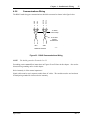
4.5.6 Communications Wiring ................................................................................................... 37
4.5.7 Magnetic Speed Pickup Wiring......................................................................................... 38
4.5.8 TS310 to HCX21 Transducer Wiring................................................................................ 40
4.5.9 TS310 to HSC3 Hydraulic Actuator Wiring...................................................................... 41
4.5.10 Current-to-Pneumatic (I/P) Transducer Wiring .............................................................. 42
4.5.11 DC Input Power & Ground Wiring ................................................................................. 43
4.5.12 AC & DC Input Power & Ground Wiring....................................................................... 43
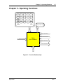
Chapter 5 - Operating Functions...........................................................................45
5.1 STARTUP SEQUENCE ............................................................................................................ 47
No Idle - Channel 82 = (0XXX)................................................................................................. 48
5.2 STARTUP SEQUENCE WITH HALT ..................................................................................... 48
5.3 STARTUP SEQUENCE VARIATIONS................................................................................... 49
Chapter 6 - Maintenance ........................................................................................51
6.1 CONFIGURATION-DIAGNOSTICS, CHANGING EPROMS............................................... 52
6.2 ELECTROSTATIC DISCHARGE AWARENESS................................................................... 53
Chapter 7 - Spare Parts..........................................................................................55
Chapter 8 - Specifications .....................................................................................57
Chapter 9 - Configuration ......................................................................................59
9.1 CHANNEL ACCESS................................................................................................................. 59
9.2 PASSWORD .............................................................................................................................. 60
9.3 CHANGING THE PASSWORD ............................................................................................... 61
9.4 ENTERING DATA.................................................................................................................... 63
9.5 FUNCTION KEYS .................................................................................................................... 64
9.6 TS310 MACHINE DATA LISTING.......................................................................................... 64
9.7 CHANNEL DEFINITIONS....................................................................................................... 68
CH 0-4 Speed And Analog Input Displays ................................................................................ 68
CH 5-7 Setpoints ........................................................................................................................ 68
CH 8-9 Analog Output Displays ................................................................................................ 68
CH 10-11 Speed Input Displays................................................................................................. 68
CH 12 Acceleration Rate * Configuration Required ................................................................. 69
CH 13-14 Critical Speed ............................................................................................................ 69
CH 15-16 Speed Range * Configuration Required .................................................................... 69
CH 17 Overspeed Trip Set * Configuration Required ............................................................... 69
CH 18-19 Speed Switch Settings ............................................................................................... 70
CH 20-33 Control Tuning * Configuration Required in CHs 20, 21 ......................................... 70
CH 34-35 V2 Limits................................................................................................................... 71
CH 36-37 Idle Speed and Idle Fuel (Limit)................................................................................ 71
CH 38-39 V1 Limits * Configuration Required......................................................................... 71
CH 40-45 Nozzle Valves............................................................................................................ 71
CH 46-61 Analog Inputs............................................................................................................. 72
CH 62-65 V1/V2 Output Calibration CHs 62, 63 * Configuration Required............................ 73
April 1998
Rev. 1
Contents
xi
CH 66 Local Load Limit.............................................................................................................74
CH 67 Local Setpoint Ramp Rate * Configuration Required ....................................................74
CH 68 KW Override Reset .........................................................................................................74
CH 69 Parallel Isochronous Delay..............................................................................................74
CH 70-71 Analog Input...............................................................................................................75
CH 72-79 Input/Output Contacts ................................................................................................77
Inputs: .......................................................................................................................................80
Outputs: ....................................................................................................................................81
CH 80 Speed Control Configuration * Configuration Required ................................................84
CH 81 Nozzle Valve Control * Configuration Required............................................................86
CH 82 Startup/Stop/Overspeed/Tuning * Configuration Required ............................................88
CH 83 2ND PID Controller ........................................................................................................91
CH 84 Status Indicators ..............................................................................................................93
CH 85 Speed Switches................................................................................................................93
CH 86 3RD PID Control.............................................................................................................95
CH 87 Synchronous Generator ...................................................................................................96
CH 88 Fail-Safe Setting * Configuration Required....................................................................96
CH 89 Gear Teeth * Configuration Required .............................................................................96
CH 90-92 B, H, and F Values .....................................................................................................96
CH 93 Gear Ratio .......................................................................................................................97
CH 94-95 Startup Tuning............................................................................................................97
CH 96 Hour Meter ......................................................................................................................97
CH 97 Last Shutdown.................................................................................................................97
CH 98 Computer Identification ..................................................................................................97
CH 99 Password..........................................................................................................................97
CH 128 Load Preset ....................................................................................................................98
CH 129 Snapback Setpoint .........................................................................................................98
CH 140 Recovery Counter, Mid Fail/Illegal Inst........................................................................98
CH 144 Recovery Counter, Power Fail & WD Timer Interrupt.................................................98
CH 155 Extraction/Admission Limit..........................................................................................99
CH 156 Regulator/Tracking PID ................................................................................................99
CH 157 MODBUS® Configuration .........................................................................................100
CH 158 Remote Setpoint Ramp Rate .......................................................................................100
CH 159 MODBUS® Checkback ..............................................................................................100
CH 160 Critical Speed Acceleration Rate ................................................................................100
9.8 MINIMUM BASIC CONFIGURATION.................................................................................101
Sample Minimum Configuration ..............................................................................................104
Chapter 10 - Configuration - Expanded Discussion.......................................... 105
10.1 ALARMS, DIAGNOSTICS, FLAGS (CH 84, 97) ................................................................105
10.2 ANALOG INPUTS (CH 54-61, 70, 71).................................................................................106
10.3 AUTOMATED HAND VALVES (CH 40-45, 81) ................................................................107
10.4 CASCADE CONTROL (CH 5, 6, 24-27, 70, 71, 83, 84) ......................................................108
10.5 CONTROL ACTION/ACTUATOR ACTION (CH 80) ........................................................109
10.6 DIGITAL INPUT/OUTPUTS (CH 72-79).............................................................................111
10.7 RESERVED FOR FUTURE USE..........................................................................................112
10.8 LIMITS, LIMIT ALARMS, GEAR RATIO (CH 13-17, 37-39, 66, 68, 83, 84, 88, 93, 155)113
10.9 OVERSPEED TEST (CH 16, 17, 72-79, 82) .........................................................................115
10.10 SPEED SETPOINTS (CH 5, 6, 81, 84)................................................................................116
10.11 SPEED CONTROL CHANNELS (CH 5, 6, 12, 20, 21, 40-45, 70, 71, 80-82, 94, 95) ......117
10.12 SPEED SWITCHES (CH 18, 19, 85)...................................................................................120
April 1998
Rev. 1
xii
TS310 Installation Configuration Operation Maintenance
10.13 START, STOP, IDLE/RUN (CH 36, 80, 82)....................................................................... 120
10.14 STROKING THE ACTUATOR (CH 62, 63)...................................................................... 121
10.15 3RD PID CONTROL, CHANNEL 86, CONFIGURATION WORD 17............................ 122
10.16 SYNCHRONOUS GENERATOR, CHANNEL 87, CONFIGURATION WORD 18 (ALSO
CHS 66, 68, 70, 71)........................................................................................................................ 125
10.16.1 Generator Drives, General........................................................................................... 126
10.16.2 Generator Drives with a TRISEN MPS390 ................................................................ 127
Generator Control - TS310 with MPS390 ............................................................................. 128
10.16.3 Generator Drives with Cascade Control...................................................................... 129
10.16.4 Auto-Synchronizing .................................................................................................... 130
10.16.5 KW Control/KW Limiting .......................................................................................... 130
10.16.6 Import or Export Control............................................................................................. 130
10.16.7 Parallel Isochronous Control ....................................................................................... 131
10.17 TRIP (CH 17, 97) ................................................................................................................. 131
10.18 TUNING CONTROLS (CH 20, 21, 28, 29, 68, 94, 95) ..................................................... 132
April 1998
Rev. 1
Contents
xiii
Illustrations
Figure 1. TS310 Front View ..................................................................................................................6
Figure 2. TS310-02 Software Block Diagram .......................................................................................8
Figure 3. Hardware Interconnections ..................................................................................................13
Figure 4. TS310 Component Layout....................................................................................................14
Figure 5. TS310 Main Board ...............................................................................................................15
Figure 6. TS310 Back View Showing Power Supply ..........................................................................16
Figure 7. Power Supply Wiring ...........................................................................................................17
Figure 8. TS310 Termination Panel .....................................................................................................18
Figure 9. Analog Output ......................................................................................................................18
Figure 10. Surface Mounting Dimensions, Front View ......................................................................23
Figure 11. Surface Mounting Dimensions, Side View and Mounting Holes ......................................24
Figure 12. Flush Mounting Dimensions, Front View..........................................................................25
Figure 13. Flush Mounting Dimensions, Side View and Mounting Holes .........................................26
Figure 14. Central Processor with Extensions.....................................................................................28
Figure 15. Simplified Application Diagram .......................................................................................28
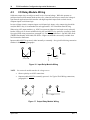
Figure 16. Input Relay Module Wiring ...............................................................................................30
Figure 17. Output Relay Module Wiring.............................................................................................30
Figure 18. Contact Input ......................................................................................................................32
Figure 19. Contact Output ...................................................................................................................33
Figure 20. TS310 to PX102 Transmitter Wiring .................................................................................34
Figure 21. Analog Input to External Power Wiring ............................................................................35
Figure 22. Two - Wire Transmitter Wiring .........................................................................................36
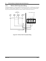
Figure 23. RS422 Communications Wiring ........................................................................................37
Figure 24. Magnetic Speed Pickup Wiring .........................................................................................38
Figure 25. Speed Pickup/Gear Dimensions .........................................................................................39
Figure 26. TS310 to HCX21 Transducer Wiring.................................................................................40
Figure 27. TS310 to HSC3 Hydraulic Actuator Wiring ......................................................................41
Figure 28. Current to Pneumatic Transducer Wiring ..........................................................................42
Figure 29. 10-40 VDC or 20-60 VDC Input Power & Ground Wiring...............................................43
Figure 30. 90-250 VAC & 100-250 VDC Input Power & Ground Wiring.........................................43
Figure 31. Function Relationships.......................................................................................................45
Figure 32. Startup Sequence ................................................................................................................47
April 1998
Rev. 1
xiv
TS310 Installation Configuration Operation Maintenance
Foreword - Important TS310 Tips
The TS310 is different from conventional prime-mover controls. Its micro-processor design and user
configurable features offer capabilities far beyond conventional electronic controllers. To ensure
that your TS310 application is a success we offer the following suggestions:
•
Review your requirements with a Triconex application engineer and have Triconex assist
in configuring and documenting your unit.
•
Order spare parts with your TS310 and have them available at startup.
•
Arrange for operator and technical personnel training prior to installation of your unit.
•
Have a Triconex field service engineer present at startup.
•
Take advantage of Triconex support services. These include:
•
Application engineering
•
Turnkey installations
Our experience shows that customers who follow these recommendations achieve the smoothest,
least expensive startup, and ultimately derive the greatest benefit and savings from their units.
IMPORTANT:
Your TS310 warranty covers factory repair or replacement of a defective item.
It does not cover:
Installation
Startup assistance
Training
On-site repairs
Please contact your local TRISEN representative if you have any questions regarding our products or
services.
April 1998
Rev. 1
Chapter 1 - Introduction
1
Chapter 1 - Introduction
This manual describes the TRISEN 310 Digital Controller.
About This Manual
As its name implies, this manual is a guide to familiarize the user with how to install it, how to
configure it and how to operate it. In depth user training is available from Triconex.
The material in this manual is arranged according to function; such as startup sequence, cascade
control, limits, and so on.
The first part of this manual is designed for customers who want to use the TS310 controller
immediately in a basic speed control application and are not interested, at least for now, in the
broader capabilities of the TS310 controller. Also, the first part of the manual is recommended as the
place to start for those who wish to become familiar with the more complex uses and functions of the
TS310, but are starting from scratch.
After becoming familiar with the simpler aspects of the TS310, you can then move further into the
manual to those functions of interest, skipping those you do not intend to use.
This manual contains the following chapters:
•
Chapter 1 - Introduction
This chapter contains information about this document and related reference documents.
•
Chapter 2 - General Description
This chapter presents a general description of the TS310 including listings of software
programs and product upgrades.
•
Chapter 3 - Hardware
This chapter describes the hardware included in the TS310.
•
Chapter 4 - Installation & Wiring
This chapter explains how to install the TS310 including mounting details, as well as
wiring scenarios for various applications.
•
Chapter 5 - Operating Functions
This chapter describes the primary startup sequence, and discusses alternate startup
sequences.
•
Chapter 6 - Maintenance
This chapter presents information on changing software EPROMS, and electrostatic
discharge awareness.
•
Chapter 7 - Spare Parts
This chapter provides a list of spare parts.
•
Chapter 8 - Specifications
This chapter lists all the specifications for the TS310.
•
Chapter 9 - Configuration
This chapter describes how to configure the TS310 and provides brief reminder channel
descriptions. This information is arranged by channel number. It is intended for use as a
quick reference guide, once you are familiar with TS310 configuration and operation.
April 1998
Rev. 1
2
TS310 Installation Configuration Operation Maintenance
•
Chapter 10 - Configuration - Expanded Discussion
This chapter explains in detail the various channels of the TS310 and how to configure
them. The information in this chapter is arranged alphabetically by operating variable
type; e.g., alarms, cascade control; through to trips, etc.
By reading this manual, you will be able to:
•
Understand the components of the TS310 Digital Control System.
•
Navigate through the display channels and enter data to configure all control, speed,
pressure and synchronization parameters.
•
Navigate through the display channels and enter data to configure all analog inputs,
analog outputs, digital inputs, digital outputs and pressure inputs.
•
Navigate through the display channels and enter data to configure all analog trips and
alarms.
Documentation Conventions
This manual uses the following typographic conventions:
Example
Description
Notes contain supplementary information.
NOTE
! CAUTION
This symbol precedes information about potential equipment damage.
! WARNING
This symbol precedes information about potential personnel hazards.
User Experience Prerequisites
Extremely advantageous, though not required, is some experience with the use of digital control
systems, or an instrumentation background.
Simple applications require little specialized knowledge of controls, electronics or computers. These
applications are easily understood and used, quickly accepted by operators, and can be configured in
a few minutes.
The basic process is:
•
Mount the TS310 controller.
•
Connect power to the TS310 power supply.
•
Connect the magnetic speed pickups.
•
Connect the control output to the valve actuator.
•
Enter values in a minimum of sixteen of the TS310 channels. (See paragraph 9.8).
Once you are familiar with details of the simpler applications, grasping the complete control
flexibility and the configuration details of more complex applications comes easy.
April 1998
Rev. 1
Chapter 1 - Introduction
3
Reference Documents
•
TS310 Troubleshooting Guide
•
TS310 ModBus Guide
•
TS310 Auto-Configuration Guide
•
TS310 Extraction & Admission Operations Guide
•
TS310 Synchronous Generator Operations Guide
April 1998
Rev. 1
Chapter 2 - General Description
5
Chapter 2 - General Description
The versatile TRISEN TS310 Digital Controller is designed using the latest computer techniques that
relate uniquely to rotating equipment. This may sound imposing, yet the TS310 remains simple to
apply and simple to operate. Computer techniques eliminate calibration, create flexibility for
applications, and provide a simple, operator-friendly interface.
The TS310 controller is totally digital in all respects. For example, the unique speed measurement
system brings the magnetic pickup frequency signal directly into the microprocessor for counting.
There is no interposing frequency-to-voltage converter or analog-to-digital converter. There is no
calibration. In fact, this measurement technique is so accurate, so precise, that two or more TS310
controllers measuring speed from the same toothed wheel will read precisely the same RPM.
Good control requires accurate measurement. The TS310 Digital Controller provides both. Although
the TS310 stands out with rugged compact simplicity as well as ease of application for simple
installations, the TS310 is equally at home solving complex control schemes with comparable ease of
application.
Hundreds of TS310s are now in use operating new and retrofit fans, pumps, compressors and other
simple applications with unsurpassed reliability. Hundreds more, however, are now controlling new
and retrofit complex generator and extraction control installations all over the world , with far more
flexible capability than has ever been available on previous governing systems.
For example, the TS310 can automatically synchronize and close the generator breaker with the touch
of a button. The TS310 easily slips from DROOP control mode into frequency control automatically
when the utility grid is lost. Then, the TS310 easily and automatically slips back into DROOP
control bumplessly when the utility tie breaker is closed again.
The TS310 will transfer to or from extraction control at the touch of a button (or from an external
contact). The TS310 provides a wide variety of possible startup sequencing, all of which are
keyboard selectable. For installations with widely varying load situations, TS310 has startup tuning
built-in.
The list goes on and on. As a matter-of-fact, a full grasp of the many TS310 possibilities will require
considerable reading.
At the same time, TS310 configuration is in sections so that simple installations will require only a
small amount of reading and a few channel entries. You don’t even have to be aware of all the other
TS310 capabilities.
The nice part is that all TS310s are alike. Learning one means you’ve learned them all. They are
completely interchangeable (with two program-software options furnished in non-volatile EPROM
chips).
One TS310 fits all, training is simplified, maintenance is reduced to almost nothing, no calibration is
required, application is simplified and standardized, and spare parts are reduced to an absolute
minimum.
April 1998
Rev. 1
6
TS310 Installation Configuration Operation Maintenance
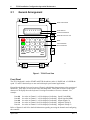
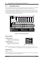
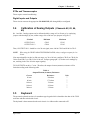
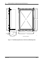
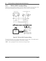
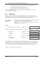
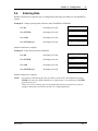
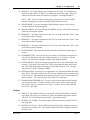
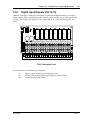
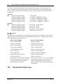
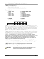
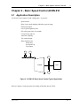
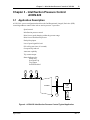
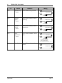
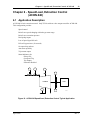
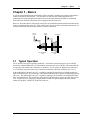
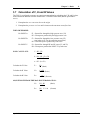
2.1
General Arrangement
NEMA 4 ENCLOSURE
8 DIGIT DISPLAY
8.8.8.8.8.8.8.8
)
)
)
)
4 INDICATOR ARROWS
REMOVABLE PLASTIC TAG
STOP
START
TRISEN
7
8
9
F2
4
5
6
F3
1
2
3
CLEAR
0
•
ENTER
F1
BEZEL
VINYL KEYBOARD
WITH TOUCHPADS
TS310
310-01
Figure 1. TS310 Front View
Front Panel
The TS310 keyboard is used to START and STOP the turbine, and to Á RAISE and  LOWER the
speed. F1 and F3 function keys are not used with simple speed control applications.
Keypad keys 0 through 9 are used to access Channels which display data pertinent to the operation of
the turbine. These keys are also used to enter and change data. These data are shown on the eightcharacter LCD display above the keyboard. Pressing two numbers will access a channel. For
example:
Press 00
Press 05
Press 08
Press 10
Press 11
the value in Channel 0 will be displayed, indicating
the value in Channel 5 will be displayed, indicating
the value in Channel 8 will be displayed, indicating
the value in Channel 10 will be displayed, indicating
the value in Channel 11 will be displayed, indicating
Speed Used (RPM)
Speed Setpoint (RPM)
Output Signal (%)
Magnetic Pickup #1
Magnetic Pickup #2
Refer to Chapters 9 and 10 for detailed information regarding accessing the channels and configuring
the controller.
April 1998
Rev. 1
Chapter 2 - General Description
2.2
7
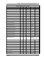
Software Programs
TS310 Digital Controller has been continuously improved over time. Serial numbers identify MOD1
through MOD4 types and software types as follows:
Serial Numbers
S83001Ds through S83028D3
S83029D3 through S86310D3
S86400D3 and up
11402-01-01 and up
Name Plate States TS310 MOD3
Name Plate States TS310 MOD4
Designation
MOD1
MOD2
MOD3
MOD3
MOD3
MOD4
Software Version
SO31--SO32--SO33--SO33--SO33--SO34---
MOD4 circuit boards interchange with MOD3, MOD2, and MOD1.
SO34R1, SO34R2, and SO33 software EPROMS will fit MOD3 and MOD4 circuit boards. These
EPROMS will NOT fit MOD1 or MOD2 circuit boards.
SO31 and SO32 software EPROMS will NOT interchange with MOD3 or MOD4 circuit boards.
The TS310 software programs reside in non-volatile EPROM memory. Two standard programs with
the DX8 option are available.
Application
EPROM 1
EPROM 2
SINGLE VALVE
03C-01049-01
08A-6-14
03C-01049-01
08B-5-14
TWO VALVE
03D-01049-01
08A-6-14
03D-01049-01
08B-5-14
SINGLE VALVE WITH DX8
08C-01009-01
08A-6-09
08C-01009-01
08B-5-09
TWO VALVE WITH DX8
08D-01009-01
08A-6-09
08D-01049-01
08B-5-09
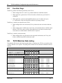
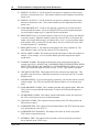
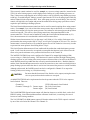
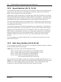
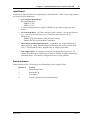
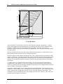
These updated programs, will be found in TS310 MOD4A controllers. These software EPROMS
will interchange with earlier TS310 MOD3 and MOD4 software, identified by TL33 and TL34. An
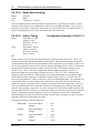
enhancement package is available for updating earlier controller Main Boards.
The figure on the following page illustrates TS310 software. Notice that the 3rd PID Control, Output
No. 2, Priority, and Ext/Adm Map Computation blocks are included only in the TS310 Two Valve
software.
TS310 Two Valve software can be configured for TS310 One Valve operation; in that case,
configuration and operation will be identical to that provided in the TS310 One Valve software.
April 1998
Rev. 1
8
TS310 Installation Configuration Operation Maintenance
TUNING
PICKUP
INPUTS
FAILSAFE
SPEED
INPUTS
SPEED
CONTROL
START /
STOP
IDLE /
RUN
DIGITAL I/O
OUTPUT
NO. 1
SPEED
REFERENCE
ANALOG
OUTPUTS
RAISE /
LOWER
OR
OUTPUT
NO. 2
(NOT USED)
SECOND PID
CONTROL
(PID 2)
ANALOG
INPUTS
ANALOG
INPUTS
TUNING
DISPLAY
ONLY
NOZZLE VALVE
CONTROL
(ALT PID 2)
DIGITAL I/O
OTHER
DIGITAL I/O
SINGLE VALVE SOFTWARE
TUNING
TWO VALVE SOFTWARE
(in addition to above)
AS ABOVE
SPEED
CONTROL
(PID 1)
PRIORITY
OR
OUTPUT
NO. 1
TO HP VALVE
OUTPUT
NO. 2
TO LP VALVE
EXT/ADM MAP
COMPUTATION
TUNING
OR
EXT/ADM STEAM PRESSURE
ANALOG INPUT
REMOTE REFERENCE
ANALOG INPUT
EXT/ADM
PRESSURE
CONTROL
(PID 3)
PRESSURE
REFERENCE
Figure 2. TS310-02 Software Block Diagram
April 1998
Rev. 1
Chapter 2 - General Description
9
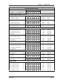
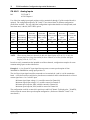
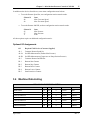
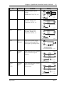
TS310 Upgrades
2.3
TS310 product improvements are listed below. Features not listed as improvements are included in
all versions of the TS310 controller.
Software Upgrades
MODEL
EPROMS
-
| MOD1
| SO31
| MOD2
| SO32
DIGITAL INPUTS
16-External Trip
17-Enable Remote Speed Setpoint
DIGITAL OUTPUTS
29-Common Alarm
30-3 Second Pulse Trip
31-Synchronizing
32-Load Breaker Closed
33-Tie Breaker Closed
34-Cascade Enabled
35-Overspeed Trip
36-Overspeed Test Enabled
37-Externally Tripped
38-Load Limited
39-Extraction/Admission Enabled
CHANNELS
81-Local/Remote Setpoint (Select)
81-Local Only Setpoint (Snapback)
82-Running Setpoint
82-Startup Tuning
84-System Problem
84-Extraction/Admission Enabled
82-V2 Enable (Extraction/Admission)
82-V2 Disable (Extraction/Admission)
86-Decoupling
86-Speed Signal
86-Speed Setpoint
86-Stand-Alone Disable 0%
86-Stand-Alone Disable 100%
97-Last Shutdown Record
128-Load Preset
129-Snapback Setpoint Configuration
144-CPU Interruption Recovery Counter
156-Regulator/Tracking PID Configuration
155-Extraction/Admission Limit
157-ModBus Configuration
158-Remote Setpoint Ramp Rate
159-ModBus Checkback
160-Critical Speed Acceleration
MOD3
SO33
MOD4
SO34R1
MOD4
SO34R2
MOD4
0(3,8)(C,D)-01049-01*
X
X
X
X
X
X
X
X
X
X
X
X
X
X
X
X
X
X
X
X
X
X
X
X
X
X
X
X
X
X
X
X
X
X
X
X
X
X
X
X
X
X
X
X
X
X
X
X
X
X
X
X
X
X
X
X
X
X
X
X
X
X
X
X
X
X
X
X
X
X
X
X
X
X
X
X
X
X
X
X
X
X
X
X
X
X
X
X
X
X
X
* Software Revision
April 1998
Rev. 1
10
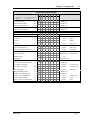
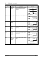
TS310 Installation Configuration Operation Maintenance
MODEL EPROMS ANALOG INPUTS
Display Only (Sq. Root)
2nd PID Meas. (Sq. Root)
3rd PID Meas. (Sq. Root)
Nozzle Valve
3rd PID Remote Set
Inverse Load Limit
Inverse 3rd PID Remote Set
External 3rd PID
Limiting Function Meas.
Inverse Limiting Function
Generator Software Adds
RMP to Minimum Governor
Setpoint Ramp Rate %
Maximum Governor
Press Start to Acknowledge
Pickup Failure
Fast Start Feature
Snapback Setpoint Feature
MOD1
SO31
MOD2
SO32
MOD3
SO33
MOD4
SO34R1
MOD4
MOD4
SO34R2 0(3,8)(C,D)-01049-01*
21
22
28
41
------10
21
22
28
41
------10
11
12
16
17
10
13
18
---100
11
12
16
17
10
13
18
19
--100
11
12
16
17
10
13
18
19
20
21
100
11
12
16
17
10
13
18
19
20
21
100
0.1
0.1
0.1
0.01
0.01
0.01
--
--
X
X
X
X
---
---
X
--
X
X
X
X
X
X
* Software Revision
NOTICE:
The TS310 Software (Release .09) contains a recovery program that will recover from
a CPU program interruption. A further discussion about the recovery program can be
found in Chapter 9, under Channel 144.
The Release .09 software utilizes an EEPROM with a larger memory. The new
EEPROM requires a jumper change. Jumper A36 is located to the left of the U36
chip. This jumper must be located in the center position. See Note on Component
Layout Figure in the next chapter for information on relocating the jumper.
Termination Board Upgrades
•
Isolated DC and AC grounding.
•
New termination has separate terminal strip for shields.
•
Speed inputs are transformer coupled.
•
Circuits for I/O module protection.
•
This board is also multi-layered.
•
All analog I/O grounds are terminated on the termination board instead of on the main
board.
April 1998
Rev. 1
Chapter 2 - General Description
11
Main Board Upgrades
•
New board is multi-layered, versus a single layer on the old board.
•
Voltage and surge protection on the speed input circuits.
•
Voltage and surge protection on the analog input circuits.
•
1% resistors are used instead of 10%.
•
Analog ground is separated from digital ground.
•
Analog inputs are self-calibrating and do not require calibration.
Power Supply Upgrades
•
Constantly loaded to improve efficiency and regulation.
•
Separate chassis and DC ground are provided.
April 1998
Rev. 1
Chapter 3 - Hardware
13
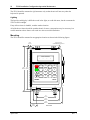
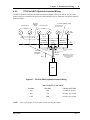
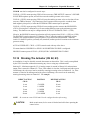
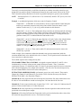
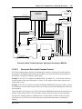
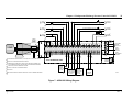
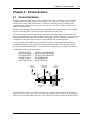
Chapter 3 - Hardware
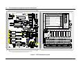
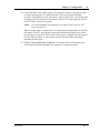
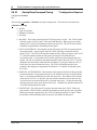
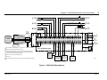
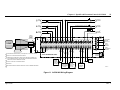
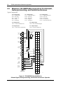
Opening the door of the TS310 reveals the Main Board on the back of the door. The TS310 hardware
interconnects as shown below.
DISPLAY
POWER
SUPPLY
TS330
MAIN
BOARD
EXTERNAL
POWER
KEYBOARD
DIGITAL
IN / OUT
COMMUNICATIONS
OUTPUTS TO
CONTROL
VALVE
TERMINATION
PANEL
ANALOG
INPUTS
MAGNETIC
SPEED
PICKUPS
Figure 3. Hardware Interconnections
A 9-pin plug-in connector supplies power to the Main Board from the Power Supply. A 40 connector
ribbon cable connects the Termination Panel to the Main Board.
A 9-conductor ribbon cable connects from the bottom of the Main Board to the keyboard. The
Display is mounted on the door side of the Main Board and is integrally connected to the Main
Board.
Hardware components are shown in the figure on the following page.
April 1998
Rev. 1
TS310 Installation Configuration Operation Maintenance
E3
D51
C1
C4
C3
C6
CR1
C2
Q3
U5
C5
POWER SUPPLY ASSEMBLY
CR2
R41
R42
R43
R44
R45
R46
CR3
CR4
C82
+
CR5
U25
C96
U41
U7
CR6
POWER TERMINALS
-
R1
U8
U1
CHASSIS GROUND TERMINAL
TP1
TP2
RN7
U26
C8
1
C84
R11
U9
R13
U19
R12
+5V
RN9
C73
C83
U34
INSTRUMENT GROUND TERMINAL
U2
C74
C76
C85
DGN
C98
U42
R2
C7
R51
C97
G
R47
R48
R49
CR29
R50
CR30
U6
H
R17
ASSY 87-5678
N
MAIN CIRCUIT BOARD
C94
U20
U27
U10
SAFETY GROUND LUG
RN1
Y1
R52
R18
C57
C58
R19
R20
C99
U43
C16
U11
C14
BR2
C13
C8
C7
C6
C5
C4
C3
C2
C1
RP1
ASSY 87-7164
M5
C45
M4
C44
M3
C43
M2
C42
C41
M1
C40
C39
C38
M6
M7
M8
T2
F1
F2
F3
F4
F5
F6
F7
F8
C23
MOV5
MOV1
MOV2
MOV3
MOV4
MOV5
MOV6
MOV7
MOV8
J1
R1
R2
RP3
RIBBON CABLE CONNECTOR
MOV3
RIBBON CABLE CONNECTOR
C21
T1
21
22
23
24
25
26
27
28
29
30
31
32
33
34
35
36
37
38
39
40
C29
4
5
6
7
8
9
10
11
12
13
14
15
16
17
18
19
20
F10
3
C28
2
G
S
5V
C27
J1
Pickup 2
Pickup 1
Shield
Shield
- 1 +
Communications
- 2 +
- 3 +
- 1 +
DIG I/O
ANA IN
- 5 +
- 3 +
- 6 +
- 4 +
- 7 +
- 1 +
ANA O/P
- 8 +
- 2 +
COM
+15V
GND
U4
C72
U15
C46
2
10
E4
R36
U14
C45
C43
9
RN10
1
C71
C42
U24
C44
R35
R40
C81
C91
U33
Q2
R34
CN1
U40
G
S
Q1
RN6
U18
FIELD WIRING
TERMINALS
RP4
RN5
C39
D
D
R30
R31
C40
R32
U32
R33
1
U39
P3
1
9
1
B39
D
E
F
1
1
A39
TERMINATION BOARD
R3
R4
R5
R6
D2
P1
F9
A
B
C
D1
MOV1
MOV2
CR11
R16
U17
C37
R29
C39
1
U31
S
R6
R7
R8
1
U38
C38
R9
C25
R21
R22
R23
R24
R25
R26
A38
C24
1
C31
C68
C22
MOV4 MOV6
C29
C30
C36
R28
B38
RN3
R27
R39
C27
C28
C67
U23
U13
RN4
C66
U30
U12
C35
1
U37
C34
1
B37
C37
R10
C33
R26
C26
C25
U3
1
R25
R38
U
F
C26
R13
R14
R15
R16
R17
R18
CR28
R21
TP3
TP4
1
R37
R11
C20 C19
R24
C65
A37
R12
R13
U21
C64
C17
CONNECTOR
R22
R23
U22
U29
C60
U36
C61
1
B36
C62
C63
1
A36
POWER
E2
SEE NOTE
INPUT POWER FUSE
BR1
C18
E
AGN +15V -15V
U16
C36
R16
C15
U28
E1
C76
C86
U35
SAFETY
GROUND
INST
GND
14
SHIELDS
SEE NOTE
NOTES: For software versions 9 and higher, jumper A36 must be moved to the center position.
Jumper E4 must be moved to the 3/4 position to change the password.
310-38
Figure 4. TS310 Component Layout
April 1998
Rev. 1
Chapter 3 - Hardware
15
TS310 Main Board
3.1
E3
D51
MAIN CIRCUIT BOARD
C94
R17
U5
C1
C4
C3
C6
CR1
C2
Q3
ASSY 87-5678
C5
CR2
R41
R42
R43
R44
R45
R46
CR29
R47
R48
R49
R50
CR30
U6
CR3
CR4
C82
CR5
U25
C96
U41
U7
CR6
R1
U8
U1
TP1
TP2
RN7
U26
1
C84
R11
U9
R13
U19
R12
+5V
RN9
C8
C73
C83
U34
U2
C74
C76
C85
DGN
C98
U42
R2
C7
R51
C97
U20
U27
U10
RN1
Y1
R52
R18
C57
C58
R19
R20
C99
U43
C16
U11
C14
BR2
R6
R7
R8
MOV1
C21
C23
MOV5
CR11
R16
U17
C37
R29
C39
1
U31
MOV3
C25
R21
R22
R23
R24
R25
R26
1
U38
C38
R9
C24
1
A38
RIBBON CABLE CONNECTOR
C68
C31
C36
R28
B38
RN3
R27
R39
U13
RN4
C67
U23
C29
C30
U30
C27
C28
1
U37
U12
C35
1
B37
C37
C34
R26
C66
C22
MOV4 MOV6
1
R25
R38
R10
MOV2
C33
C26
R13
R14
R15
R16
R17
R18
CR28
R21
U3
C65
R37
R11
C20 C19
R24
TP3
1
C64
A37
R12
U21
C17
CONNECTOR
R22
R23
C60
C61
U22
U29
TP4
1
C36
U36
C62
C63
1
B36
POWER
E2
SEE NOTE
A36
C18
R13
AGN +15V -15V
U16
BR1
C13
R16
E1
U28
C15
C76
C86
U35
1
J1
5V
GND
U4
C72
C46
U15
2
10
E4
R36
U14
C45
C43
9
RN10
1
C71
C42
U24
C44
R35
R40
C81
C91
U33
U18
Q2
R34
CN1
G
Q1
RN6
S
RN5
U40
G
S
R30
R31
C40
R32
U32
R33
1
U39
P3
1
9
1
B39
C39
D
D
A39
SEE NOTE
NOTES: For software versions 9 and higher, jumper A36 must be moved to the center position.
Jumper E4 allows access to overspeed test, diagnostics and other functions.
310-41
Figure 5. TS310 Main Board
April 1998
Rev. 1
16
TS310 Installation Configuration Operation Maintenance
TS310 Power Supply
3.2
INST
GND
N G
-
H
+
U
F
S
E
310-5
Figure 6. TS310 Back View Showing Power Supply
The Power Supply is located in the upper half of the back of the TS310 cabinet. Power consumption
is less than 10 watts. In-rush currents at power-up are:
•
0.25 amps for 110 V source;
•
2.5 amps for 24 V source; and
•
5 amps for 10 V source.
Number 14 AWG wire should be used for power source connections.
The POWER SUPPLY ASSEMBLY converts the input power source (as measured on the main
board, just above the lower left-hand screw as shown in the figure above) to
•
+5.125 VDC (±0.05 V),
•
+15 VDC (±0.75 V), and
•
-15 VDC (±0.75 V),
to operate the TS310 circuitry.
NOTE:
Power Supply calibration is normally a one-time, factory assembly adjustment. The
proper Power Supply measurement is made at two test points, +5V and DGN, on the
TS310 main board, on the back side of the front door of the TS310 enclosure (reference
figure of Main Board in this chapter), with the power supply connected to the main board.
The standard power supply is rated at 25 watts and operates on 100 to 350 VDC or 90 to 250 VAC,
at 50 to 440 Hz. Input power is connected to barrier-type, 6-32 screw terminals. A 0.75 amp slowblow fuse, TRISEN Part Number 9276-0000, and fuse holder are mounted on the power supply
chassis along with an EMI filter and surge suppressors.
April 1998
Rev. 1
Chapter 3 - Hardware
17
For battery back-up installations, a special TS310 power supply operates on 12 VDC furnished by the
battery back-up option. The TS310 12 VDC power supply is rated at 10 to 40 VDC input. A 5 amp
slow-blow fuse is furnished with this power supply.
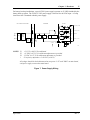
FOR AC INPUT SUPPLIES ONLY
CONVERTER
OUTPUT
+ DC
INPUT
REG
AC
INPUT
BRIDGE
RECTIFIER
RFI
FILTER
STARTING
CIRCUIT
CONTROL
CIRCUIT
BASE
DRIVE
CONVERTER
TRANSISTOR
+
V1 +5-10 VDC (+/-0.05V)
-
COM
+
V2 +15 VDC (+/-0.75V)
-
V4 GROUND
-
REG
+
ACTIVE
SOFT
START
CIRCUIT
V3 -15 VDC (+/-0.75V)
FILTER
CAP
- DC
CHASSIS
OPTO-ISOLATOR
REG
INPUT
P1*
NOTES: V1
V2
V3
*
310-06
+5.125 V (±0.05 V) Precalibrated.
+15 VDC (±0.75 V) No calibration adjustment is provided.
-15 VDC (±0.75 V) No calibration adjustment is provided.
P1 is factory adjusted to +5-10 VDC (±0.05 V)
All voltages should be checked/measured at test points "+5V" and "DGN" on main board,
with power supply connected to main board.
Figure 7. Power Supply Wiring
April 1998
Rev. 1
18
TS310 Installation Configuration Operation Maintenance
3.3
Termination Panel
The Termination Panel is located in the lower half of the back of the TS310 cabinet. Forty terminals
accommodate all I/O. Eight sockets, M1 through M8, accommodate the digital I/O relays.
Fuses F1 through F8 protect the eight digital I/O circuits external to the TS310. These are 5 amp
plug-in picofuses Part Number 9274-0000. F10 protects the +15 VDC circuit (terminal 20). This is a
1/2 amp picofuse Part Number 9250-0000. F9 protects the internal 5 VDC I/O relay circuit. This is
a 1/2 amp plug-in picofuse Part Number 9250-0000.
C26
C8
C7
C6
C5
C4
C3
C2
M5
C45
M4
C44
M3
C43
M2
C42
C41
C40
C39
C38
M1
M6
M7
M8
T2
F1
F2
F3
F4
F5
F6
F7
F8
MOV1
MOV2
MOV3
MOV4
MOV5
MOV6
MOV7
MOV8
J1
R1
R2
RP3
RIBBON CABLE CONNECTOR
T1
ASSY 87-7164
R5
R6
RP1
D
E
F
C1
R3
R4
D2
P1
F9
A
B
C
D1
C25
21
22
23
24
25
26
27
28
29
30
31
32
33
34
35
36
37
38
39
40
C29
3
4
5
6
7
8
9
10
11
12
13
14
15
16
17
18
19
20
F10
2
C28
1
C27
RP4
Pickup 2
Pickup 1
Shield
Shield
- 1 +
Communications
- 2 +
- 3 +
- 1 +
DIG I/O
ANA IN
- 5 +
- 3 +
- 6 +
- 4 +
- 7 +
- 1 +
ANA O/P
- 8 +
- 2 +
COM
+15V
SHIELDS
310-40
Figure 8. TS310 Termination Panel
Analog Outputs
Analog Output No. 1
Jumper B-A for 0 to 200 mA range
Jumper B-C for 0 to 20 mA range
Analog Output No. 2
Jumper E-D for 0 to 200 mA range
Jumper E-F for 0 to 20 mA range
NOTE:
A
B
C
R3
D
E
F
R5
R4
R6
Figure 9. Analog Output
B-A and E-D jumpers multiply output configurations in Channels 62, 63, 64, 65 by 10!
That is, if Channel 62 = 3 and Channel 63 = 16, No. 1 analog output will be 30 to 160 mA.
Analog Inputs
High level - 0 to 10 VDC
Precision dropping resistors must be installed across terminals to convert 4 to 20 mA current signal
to 1 to 5 VDC signal (or 2 to 10 VDC, if appropriate).
April 1998
Rev. 1
Chapter 3 - Hardware
19
RTDs and Thermocouples
These require external conditioning.
Digital Inputs and Outputs
These circuits must use the appropriate I/O MODULE (M1 through M8) as configured.
3.4
Calibration of Analog Outputs (Channels 62, 63, 64,
65)
No. 1 and No. 2 analog outputs can be calibrated within a range of 0 to 20 mA or, by employing
jumpers which multiply by ten, within a range of 0 to 200 mA (see jumpers in Figure 9).
Schedule
OUTPUT NO. 1
OUTPUT NO. 2
Minimum
CH 62
CH 64
Maximum
CH 63
CH 65
Thus, if OUTPUT NO. 1 should be a 4 to 20 mA signal, enter 4.00 in CH 62 and 20.00 in CH 63.
NOTE:
When using the TRISEN M360 TESTER/SIMULATOR, always configure outputs for 0 to
20 mA.
If an output should be in the 0 to 200 mA range, say 30 to 160 mA, configure CH 62 (or CH 64) for
3.00 mA and CH 63 (or CH 65) for 16.00 mA. Jumpers (paragraph 3.3) are then set to multiply by
ten, resulting in the 30 to 160 mA output signal(s).
TS310 OUTPUTS can drive 7 volts. Therefore, the output element (actuator) resistance will be
limited according to the following table.
Table A.
Output Element (Actuator) Resistance
Current
20 mA
40 mA
100 mA
160 mA
200 mA
3.5
Resistance
350 ohms
175 ohms
70 ohms
43 ohms
35 ohms
Volts
7
7
7
7
7
Keyboard
The operator keyboard consists of a membrane type keypad which is bonded to the door of the TS310
enclosure and then sealed with a bezel.
The keyboard is then connected to the main circuit via a ribbon cable connected to P3.
April 1998
Rev. 1
Chapter 4 - Installation & Wiring
21
Chapter 4 - Installation & Wiring
The discussion in this chapter is not theoretical. All recommendations listed here are the result of
field experience. If they are followed, a good installation will result. If they are not followed,
operating problems may occur.
The TRISEN TS310 digital controller is a high performance, high speed, sensitive control system.
As such, it requires and deserves careful installation.
CONSULT THE FACTORY
IF IN DOUBT ABOUT
ANY INSTALLATION
4.1
Installation
The following recommendations have been compiled from actual field service startup and service
call experience. These highlight many of the common problems which can be encountered when
installing TS310 controllers.
Choosing a Location for the TS310
The location where the TS310 will be mounted in the field is a critical decision. Factors such as
accessibility, lighting, and temperature affect the success of the installation. Other important factors
include area classification, length of wiring, proximity to sources of electrical noise, and availability
of instrument ground. The following should be considered in making this decision.
Noise
Prior to mounting the TS310, an inspection of the area should be performed to check for sources of
electrical noise. Motors, radio antennas, arcing contacts, etc., may cause interference problems. If
the TS310 must be mounted near known sources of noise, steel conduit must be used for all wiring,
and the wires should be kept as short and direct as possible.
Temperature
Although the TS310 operating temperature is specified from 0 to 160° F, areas where the temperature
will remain constant at or near the limits should be avoided. Temperature extremes also make
operation and service inconvenient.
Access
Since the TS310 usually is operated through the front panel, it should be mounted so that the operator
can stand in front of the controller comfortably. The display should be at eye level; the most
common installations are between 5 feet and 5 feet, 6 inches high.
Service access should also be considered. Assure that:
April 1998
−
the door can be fully opened;
−
the unit will not be subjected to steam or dripping
−
water or other liquids; and
−
that locating the TS310 in a given area will not be in violation of area classification
with the door open.
Rev. 1
22
TS310 Installation Configuration Operation Maintenance
The TS310 should be mounted to rigid structures only so that the unit will not sway when the
keyboard is operated.
Lighting
The liquid crystal display is difficult to read in low light, so avoid dark areas; but do not mount the
TS310 in direct sunlight.
If any of these items is doubtful, consider another location.
All of the above factors should be considered and, of course, compromises may be necessary, but
careful attention to these factors will result in a more successful installation.
Mounting
The TS310 should be mounted in an appropriate location as shown in the following figures.
0.375"
(9.5mm)
0.2812" (TYP 4 PL)
ACCOMMODATES1/4" BOLTS
8.8.8.8.8.8.8.8.
)
)
)
)
13.50"
12.75"
343mm) 324mm)
STOP
F1
7
8
9
START
F2
4
5
6
F3
1
2
3
CLEAR
0
•
ENTER
TRISEN
TS310
310-33
5.0"
(127mm)
8.00"
(203mm)
10.25"
(260mm)
2.625"
(66.7mm)
April 1998
Front View
Rev. 1
Chapter 4 - Installation & Wiring
23
Figure 10. Surface Mounting Dimensions, Front View
April 1998
Rev. 1
24
TS310 Installation Configuration Operation Maintenance
12.75"
(324mm)
1"
CONDUIT
HUB
2.0"
(51mm)
8.0"
(203mm)
310-34
5.56"
(141mm)
Right Side View
Mounting Hole Pattern
Figure 11. Surface Mounting Dimensions, Side View and Mounting Holes
April 1998
Rev. 1
Chapter 4 - Installation & Wiring
25
0.281"
(7.14mm)
TYP. 4 PL
8.8.8.8.8.8.8.8.
)
)
)
)
16.00"
15.00"
(406.4mm) (381.0mm)
STOP
F1
7
8
9
START
F2
4
5
6
F3
1
2
3
CLEAR
0
•
ENTER
TRISEN
TS310
310-31
6.00"
(152.4mm)
13.50"
(342.9mm)
14.50"
(368.3mm)
Figure 12. Flush Mounting Dimensions, Front View
April 1998
Rev. 1
26
TS310 Installation Configuration Operation Maintenance
CUT
OUT
15.00"
(381.0mm)
12.5"
(317.5mm)
3.00"
(76.2mm)
0.435"
(11.05mm)
14.00"
15.00"
(355.6mm) (381.0mm)
0.281"
(7.14mm)
TYP 4 PL
13.5"
(342.9mm)
6.12"
(155.5mm)
310-32
Right Side View
Mounting Hole Pattern
Figure 13. Flush Mounting Dimensions, Side View and Mounting Holes
April 1998
Rev. 1
Chapter 4 - Installation & Wiring
4.2
27
Wiring - General
Failure to use the following wiring recommendations will result in instability of control and/or
intermittent shutdown from random electrical noise which can and will enter the TS310 if these
procedures are not followed.
•
Keep all wire runs as short and direct as possible. Long wire runs are vulnerable to
picking up stray electrical noise. Also, long wire runs are costly, but remote mounting
may be necessary because of area classification, convenience, or other extreme field
conditions.
•
All signal wires (terminals 1 through 23 and terminal 40) must be shielded twisted pairs.
Shields must terminate only at the TS310. The other end of the shield should be left
floating and taped.
•
Wire size should be selected to provide one ohm of resistance or less over the entire
length of the run.
•
Place wiring in conduit or cable trays.
•
Use rigid steel conduit for all installations subject to high levels of electrical noise, or
that must use long wire runs.
•
Never run analog signal wires in conduit or cable trays with any AC or DC power wiring.
In fact, signal wiring should be separated as far as possible from high voltage AC or DC
wiring.
•
Never run signal wires in conduit or cable trays with wiring which provides power to
inductive loads, such as motors, solenoids, etc.
•
Use care when running signal wiring near to or crossing conduit or wiring that supplies
power to motors, solenoids, lighting, horns, bells, etc.
•
Avoid bringing TS310 wiring into junction boxes which contain other wiring.
April 1998
Rev. 1
28
TS310 Installation Configuration Operation Maintenance
Grounding
Grounding complex systems to minimize electro-magnetic interference (EMI) is a complex task.
Guidelines are difficult to develop since all systems have different operating characteristics, are
configured differently, and are exposed to different environments.
A basic TS310 control system can be viewed as a central system with extensions, as shown, very
simply, in Figure 14. Integral elements extend from the central system at long physical and electrical
distances. Figure 15 illustrates a simplified application.
8 DIGIT
OPERATOR
DISPLAY
8.8.8.8.8.8.8.8.
)
)
)
)
STOP
F1
7
8
START
F2
4
5
6
F3
1
2
3
CLEAR
0
•
TRI-SEN
9
ENTER
TS310
AC POWER
AC Power
Pickup 2
OUTPUT
P/I Transmitter
PICKUPS
V2
Pickup 1
V1
TURBINE
I/P V1
I/P V2
PRESSURE TRANSMITTER
Figure 14. Central Processor with
Extensions
Figure 15. Simplified Application
Diagram
The system shown in the figures above is distinguished from a distributed system in that the extended
elements obtain power from the central element (TS310). Connections to a power source are not
made anywhere except at the TS310.
If both the source end and the load end of a cable pair in a noisy environment are grounded, common
mode interference is likely to occur. Generally, the end that maximizes the signal-to-noise ratio in
the loop should be grounded; i.e., usually the source end. However, in the case of a TS310
installation, where multiple sensors are feeding one processor, grounding every source end would
ultimately create a multiple-grounded system. Therefore, the TS310 end as the ground point is the
most practical solution in order to maintain a single-point ground.
April 1998
Rev. 1
Chapter 4 - Installation & Wiring
29
The central element (the TS310) of this system should be grounded as though it were an isolated
system. TRISEN control systems involve relatively low frequencies; therefore, a single-point tree or
star grounding scheme is used. The ground node would be at the central element (TS310) with one
connection (the safety ground) made to the structure. The transducers should be floated; i.e., not
grounded at the transducer end. Shielded, twisted pair cable should be used and grounded at the
TS310 end only.
Cable Routing
To avoid inter-cable noise coupling (crosstalk), it is necessary to identify and categorize the separate
cable routings.
Category 1:
AC power cables - noise carriers
Category 2*:
DC distribution cables - noise carriers and/or victims
Category 3:
Signal and logic cables - victims
NOTE:
a)
Analog, low level signals
b)
Digital signals
Signal wires from relays, circuit breakers, thermal switches, etc., fall into Category 2.
Basic guidelines for routing these cables are:
Category 1:
Category 2:
Category 3:
Route along frame members and in separate metal cable trays.
Route along frame members and metal cable trays, but separate from
Category 1. (Avoid open space hanging.)
Route as far as possible from Categories 1 and 2.
In general,
• For cables from Subcategory 3a), the spacing is dependent on the sensitivity of the
circuits they are connected to; a spacing of 25 cm (10 inches) from Category 1 for every
meter of possible parallel run is required to protect an analog circuit having 10 mV
sensitivity.
•
Cables from Subcategory 3b) which carry digital signals should be placed 2.5 cm
(1inches) from Category 1 for every 1 meter of their possible parallel run.
Remember that power wiring not only carries 60 Hz voltages, but it also has associated line spikes
which couple strongly with near-by victim wiring.
Example: If a routing constraint forces analog signals to be run parallel to AC cables over a distance
of 10 meters, a separation of 10 X 2.5 cm = 25 cm is required.
April 1998
Rev. 1
30
TS310 Installation Configuration Operation Maintenance
4.3
I/O Relay Module Wiring
Solid-state output relays are subject to small levels of current leakage. While this presents no
problem when used with normal loads such as coils, solenoids, hard relays or motors, the leakage is
significant for applications which interface with high impedance inputs such as alarm circuits,
computer inputs or solid-state logic.
In cases of alarm circuits, computer inputs or solid-state logic inputs, a dry contact relay should be
used; the DRY5 relay is recommended for such applications. See Termination Panel Wiring.
When using a DC output module (e.g., ODC5) to operate an inductive load, such as a trip solenoid,
breaker closing coil or electro-mechanical relay, the load MUST be by-passed by a protective diode.
See typical field wiring connections, paragraph 4.4. For most applications a 1 amp 400 VDC diode
(TRISEN Part Number 4092-0000) will suffice. Higher current diodes are usually available from
local electronics distributors.
Input modules MUST be powered, either internally or externally. See typical field wiring connection
sketches in the following paragraphs.
Wrong
Voltage
Source
Right
External
Contact
¦
External
Contact
Figure 16. Input Relay Module Wiring
NOTE:
Be certain the module matches the voltage source.
•
Observe polarity on all DC connections.
•
Output modules MUST be externally powered. See Typical Field Wiring connections,
paragraph 4.4.
Load
Load
Voltage
Source
Wrong
¦
Right
Figure 17. Output Relay Module Wiring
April 1998
Rev. 1
Chapter 4 - Installation & Wiring
31
TS310 Termination Panel Wiring
4.4
Refer to Figure 7 and wire the termination panel as follows:
1
No. 1 PICKUP (+)
21
No. 2 PICKUP (-)
2
No. 1 PICKUP (-)
22
No. 2 PICKUP (+)
3
PICKUP SHIELD
23
PICKUP SHIELD
4
RS422 XMIT B (-)
24
No. 1 CONTACT (-)
5
RS422 XMIT A (+)
25
No. 1 CONTACT (+)
6
RS422 REC B (-)
26
No. 2 CONTACT (-)
7
RS422 REC A (+)
27
No. 2 CONTACT (+)
8
No. 1 ANALOG IN (-)
28
No. 3 CONTACT (-)
9
No. 1 ANALOG IN (+)
29
No. 3 CONTACT (+)
10
No. 2 ANALOG IN (-)
30
No. 4 CONTACT (-)
11
No. 2 ANALOG IN (+)
31
No. 4 CONTACT (+)
12
No. 3 ANALOG IN (-)
32
No. 5 CONTACT (-)
13
No. 3 ANALOG IN (+)
33
No. 5 CONTACT (+)
14
No. 4 ANALOG IN (-)
34
No. 6 CONTACT (-)
15
No. 4 ANALOG IN (+)
35
No. 6 CONTACT (+)
16
No. 1 ANALOG OUT (-)
36
No. 7 CONTACT (-)
17
No. 1 ANALOG OUT (+)
37
No. 7 CONTACT (+)
18
No. 2 ANALOG OUT (-)
38
No. 8 CONTACT (-)
19
No. 2 ANALOG OUT (+)
39
No. 8 CONTACT (+)
20
+15 VDC
40
SYSTEM COMMON
NOTE:
April 1998
Terminals that are shaded are for external power;
Terminals 16 through 19 are for TS310 power.
Rev. 1
32
TS310 Installation Configuration Operation Maintenance
4.5
Typical Field Wiring
Installation should carefully follow recommendations listed in this chapter.
It is extremely important to avoid installation mistakes. It is equally important to avoid improper
grounding and shielding practices as outlined in this chapter.
TS310 Contact Input Wiring
4.5.1
Power requirements depend upon input module used.
Module
IDC5
IAC5
IAC5A
NOTE:
Load
10-32 VAC/DC
90-140 VAC/DC
180-280 VAC/DC
Amps
25 mA
11 mA
6.5 mA
Internal power (Terminals 20 and 40), +15 VDC and common, may be used for contact
input circuits. Use IDC5 modules. Be careful to observe polarity. Positive 15 VDC at a
maximum of 250 mA is provided to interface field contacts and specific sensors.
R
-
+
+
TS310-13
Figure 18. Contact Input
April 1998
Rev. 1
Chapter 4 - Installation & Wiring
4.5.2
33
TS310 Contact Output Wiring
Power requirements depend on load and output module used:
Module
200 VDC/VAC
5/60 VDC
12/140 VAC
24/280 VAC
5/200 VDC
Load
DRY5
ODC5
OAC5
OAC5A
ODC5A
N.O. OR N.C.
-
+
+
NOTE
-
310-14
NOTE:
Omit diode if circuit is AC powered.
Figure 19. Contact Output
For inductive DC loads such as a solenoid, install 1 AMP 1000 PIV diode (part number 4092-0000)
across the load as shown to protect the solid state module.
For high impedance alarm systems use module DRY5. Do not use internal TS310 power from
Terminals 20 and 40 for powering output loads.
Do not exceed module current ratings of
3 AMP for ODC5, OAC5 and OAC5A;
1 AMP for ODC5A (1 second surge - 5 AMP);
and
10 VA for DRY5 (200 volts maximum).
Do not use +15 VDC (Terminal 20) for contact outputs!
April 1998
Rev. 1
34
TS310 Installation Configuration Operation Maintenance
4.5.3
TS310 to PX102 Transmitter Wiring
The PX102 transmitter is a voltage output device powered by the TS310 +15 VDC supply (Terminals
20 and 40). PX102 provides a nominal 0.5 to 5.5 VDC signal used by the TS310 as an analog input
for process measurement for backpressure control, extraction, inlet pressure control, etc.
TO SHIELD
TERMINAL STRIP
40
COM
1
2
3
V OUT
20
GND
+
+15 V
-
PX102 TERMINAL STRIP
TS310 FIELD
310-15
20-16 AWG
Figure 20. TS310 to PX102 Transmitter Wiring
April 1998
Rev. 1
Chapter 4 - Installation & Wiring
35
TS310 Analog Input to 4 to 20 mA External Power Wiring
4.5.4
An analog input powered by an external circuit should be connected as shown in the figure below.
250 OHM
PRECISION RESISTOR
-
+
40 COM
TO SHIELD
TERMINAL STRIP
TS310
FIELD
4-20 mA INPUT
Figure 21. Analog Input to External Power Wiring
! CAUTION
NOTE:
Beware of ground loops. Use an isolator when in doubt.
If the 4 to 20 mA analog source is capable of driving a 500 OHM precision resistor, twice
the resolution will be obtained from the analog input. (The voltage drop will be 2 to 10
volts rather than the 1 to 5 volts obtained across a 250 OHM precision resistor.) The
TS310 analog input channel must be configured accordingly.
! CAUTION
April 1998
The TS310 input common mode range must not be exceeded. This range is
approximately ±12 V from instrument ground.
Rev. 1
36
TS310 Installation Configuration Operation Maintenance
TS310 to Two-Wire Transmitter Wiring
4.5.5
Two-wire transmitters (Foxboro, Rosemount, Gould, etc.) should be wired to the TS310 as shown in
Figure 17.
NOTE:
These cannot be powered from the TS310.
! CAUTION
Beware of ground loops. Use an isolator when in doubt.
NOTE: ONLY INSTALL THIS JUMPER IF TRANSMITTER POWER SUPPLY IS FLOATING.
250 OHM
PRECISION RESISTOR
-
+
40 COM
TO SHIELD
TERMINAL STRIP
TS310
FIELD
EXTERNAL
24 VDC
POWER SUPPLY
310-17
+
+
-
Figure 22. Two - Wire Transmitter Wiring
April 1998
Rev. 1
Chapter 4 - Installation & Wiring
4.5.6
37
Communications Wiring
XMB
XMA
RECB
RECA
The RS422 multi-drop port communications should be connected as shown in the figure below.
4
5
6
7
+
-
+
To Shield
Terminal Strip
18-24 AWG
Twisted
Shielded Pair
-
+
REC
-
+
XMIT
REMOTE SYSTEM
330-04
Figure 23. RS422 Communications Wiring
NOTE:
The shields grounds to Terminals 3 or 23.
Grounding practice must follow instructions on Figures 29 and 30 later in this chapter. Also see the
discussion on grounding earlier in this chapter.
Noise immunity is of the utmost importance!
Signal cables must be run in separate conduit from AC cables. The conduits must be steel and must
be multipoint grounded for increased noise immunity.
April 1998
Rev. 1
38
TS310 Installation Configuration Operation Maintenance
4.5.7
Magnetic Speed Pickup Wiring
The TS310 controller requires an accurate and dependable sensed speed signal. Standard two-wire
magnetic speed pickups should be used. Other devices can be used in some instances; in this case,
consult the factory. Magnetic pickup connections should be made as shown in the figure below.
EXPLOSION PROOF PICKUP
WITH CHASSIS GROUND
STANDARD PICKUP
+
+
-
Insulate Shield at
Pickup End
(do NOT Ground
or Terminate)
-
Ground to
Chassis
330-35
Insulate Shield at
Pickup End
(do NOT Ground
or Terminate)
330-36
Figure 24. Magnetic Speed Pickup Wiring
Polarity is for active pickups only, not for passive pickups.
Signal cables must be run in separate conduit from AC power cables. Conduits must be steel and
must be multi-point grounded for increased noise immunity.
NOTE:
Insulate shields at the pickup. Shields must be grounded only as shown.
A pickup fail alarm will latch until acknowledged by pressing the START key.
April 1998
Rev. 1
Chapter 4 - Installation & Wiring
39
The choice of gear to use with a magnetic speed pickup is very important in obtaining a good speed
signal. For best results the five items below should be considered:
•
Dimension of tooth top surface should be equal to or more than pickup pole piece
diameter.
•
Tooth height should be equal to or more than the space between the teeth.
•
Space between teeth should be approximately three times pole piece diameter.
•
Air gap between pickup pole piece and tooth top surface should be as small as possible,
0.015" minimum.
NOTE:
•
Pickup gap may have to be larger if clearance problems exist.
Gear width should be at least equal to or more than pole piece diameter of pickup.
The previous suggestions are shown graphically in the figure below.
Speed
Pickup
E
A
D
C
F
B
Gear
A
B
C
E
F
equal to or greater than D
equal to or greater than C
equal to or greater than three times D
as close as possible, typically 0.015 inch minimum
equal to or greater than D
Figure 25. Speed Pickup/Gear Dimensions
April 1998
Rev. 1
40
TS310 Installation Configuration Operation Maintenance
TS310 to HCX21 Transducer Wiring
4.5.8
The HCX21 current to hydraulic transducer should be connected as shown in the figure below. The
HCX21 provides hydraulic pressure proportional to the TS310 4 to 20 mA current output.
ANALOG OUTPUT
COMMAND
4-20 mA
TWISTED
SHIELDED PAIR
TO SHIELD TERMINAL STRIP
+
40
COM
20
+15 V
GND
TWISTED
SHIELDED PAIR
TS310
FIELD
SPLICE IN
CONDUIT
TWISTED
PAIRS
HCX21
WHITE
RED
BLACK
WHITE
TS310-19
Figure 26. TS310 to HCX21 Transducer Wiring
The signal cables must be run in separate conduit from the AC power cables. The conduits must be
steel and must be multi-point grounded for increased noise immunity.
NOTE:
Refer to paragraph 10.14 for a discussion of testing the output.
April 1998
Rev. 1
Chapter 4 - Installation & Wiring
41
TS310 to HSC3 Hydraulic Actuator Wiring
4.5.9
The HSC3 Hydraulic Actuator should be connected as shown in the figure below. A 0 to 2 inch
position signal is available on the green wire and optionally may be connected as an analog input for
position readout.
TO SHIELD
TERMINAL
STRIP
ANALOG INPUT
-
TO SHIELD TERMINAL STRIP
ANALOG OUTPUT
+
-
TERMINATE SHIELD NO CONNECTION
+
COMMAND
4-20 mA
TWISTED
SHIELDED PAIR
40
COM
20
+15 V
TWISTED
PAIRS
GND
TWISTED
SHIELDED PAIR
TS310
FIELD
WHITE
WHITE
BLACK
POSITION
FEEDBACK
(OPTIONAL)
RED
SPLICE IN
CONDUIT
GREEN
NOTE: DO NOT MIX WHITE
WIRES BETWEEN PAIRS.
ACTUATOR COULD BE
DAMAGED
HSC3
TS310-22
Figure 27. TS310 to HSC3 Hydraulic Actuator Wiring
HSC3 FORCE AVAILABLE
NOTE:
Pressure
Lbs Stall
Velocity at 1/2 Stall
100
180
5 inches per second
400
720
10 inches per second
1000
1800
14 inches per second
Refer to paragraph 10.14 for a discussion of testing the output.
April 1998
Rev. 1
42
TS310 Installation Configuration Operation Maintenance
4.5.10
Current-to-Pneumatic (I/P) Transducer Wiring
This transducer is used to convert TS310 output to a 3 to 15 psig or other pneumatic signal to operate
pneumatic actuators.
An I/P transducer should be connected as shown in the figure below.
ANALOG OUTPUT
-
+
TO SHIELD
TERMINAL
STRIP
TS310
FIELD
TWISTED
SHIELDED PAIR
18-24 AWG
AIR
SUPPLY
+
3-15 PSIG
OUTPUT
TS310-23
Figure 28. Current to Pneumatic Transducer Wiring
NOTE:
Refer to paragraph 10.14 for a discussion of testing the output.
April 1998
Rev. 1
Chapter 4 - Installation & Wiring
4.5.11
43
DC Input Power & Ground Wiring
TO SHIELD
TERMINAL STRIP
V3
V4
V2
INSTRUMENT GROUND
1
GRN
VDC RETURN
-
+ VDC
+
Chassis
BLU
-
5 ASB
DC
+
BRN
14 AWG PER
NEC 250-95
SAFETY GROUND
EARTH CONNECTION
TS310
POWER SUPPLY
10-40 VDC
OR
20-60 VDC
COM
SAFETY GROUND
CUSTOMER
POWER
OUTPUT
V1
INPUT
AC
TS310
POWER
TERMINALS
AC
AC
NOTES: OUTPUTS SHOULD BE CHECKED UNDER
LOAD AT THE MAIN BOARD TEST POINTS
FIELD
CUSTOMER’S
HIGH-QUALITY
INSTRUMENT
GROUND
(<1 OHM)
1
TS310
MUST BE REMOVED IF SEPARATE
INSTRUMENT GROUND IS CONNECTED.
INTERNAL WIRING BY TRISEN
CHASSIS CONDUCTOR PATHWAY
TS310 SAFETY
GROUND LUG
CUSTOMER WIRING
310-35
Figure 29. 10-40 VDC or 20-60 VDC Input Power & Ground Wiring
4.5.12
AC & DC Input Power & Ground Wiring
TO SHIELD
TERMINAL STRIP
V3
V4
V2
INSTRUMENT GROUND
1
CUSTOMER
POWER
OUTPUT
V1
SAFETY GROUND G
GRN
GRN
N
N
BLU
BLU
H
H
.75 ASB
BRN
Chassis
DC
+
BRN
FILTER
SAFETY GROUND
EARTH CONNECTION
14 AWG PER
NEC 250-95
TS310
POWER SUPPLY
90-250 VAC
OR
100-250 VDC
COM
TS310
POWER
TERMINALS
INPUT
AC
AC
AC
NOTES: OUTPUTS SHOULD BE CHECKED UNDER
LOAD AT THE MAIN BOARD TEST POINTS
CUSTOMER’S
HIGH-QUALITY
INSTRUMENT
GROUND
(<1 OHM)
FIELD
1
TS310
MUST BE REMOVED IF SEPARATE
INSTRUMENT GROUND IS CONNECTED.
INTERNAL WIRING BY TRISEN
CHASSIS CONDUCTOR PATHWAY
TS310 SAFETY
GROUND LUG
CUSTOMER WIRING
310-36
Figure 30. 90-250 VAC & 100-250 VDC Input Power & Ground Wiring
April 1998
Rev. 1
Chapter 5 - Operating Functions
45
Chapter 5 - Operating Functions
STOP
F1
7
8
9
START
F2
4
5
6
F3
1
2
3
CLEAR
0
•
ENTER
TS310
TRISEN
8.8.8.8.8.8.8.8.
Display
Keypad
)
)
)
)
2 Magnetic Speed Pickups
4 AI or Measurements, Etc.
RS 422 Communications
TS310
ELECTRONICS
8 Digital Inputs/Outputs
Power
2 AO To Control Valves
Figure 31. Function Relationships
April 1998
Rev. 1
46
TS310 Installation Configuration Operation Maintenance
Commonly used keyboard and operating functions are listed below:
•
The START key will initiate the startup sequence.
•
The STOP key will close the governor valve, stopping the turbine.
•
The RAISE key ▲ will increase the reference at the setpoint ramp rate.
•
The LOWER key ▼ will decrease the reference at the setpoint ramp rate.
•
During startup, pressing RAISE or LOWER momentarily will halt acceleration.
•
Pressing RAISE or LOWER keys for less than one second will change turbine speed by
ONE RPM regardless of the setpoint ramp rate setting in Channel 67.
•
Pressing the F2 function key after a HALT will resume acceleration.
•
ACCELERATION (Channel 12) in RPM per minute is only used during startup and is
no longer used after turbine speed reaches the minimum governor.
•
SETPOINT RAMP RATE is defined as percent per second of maximum governor. It is
used any time the speed is changed by the RAISE or LOWER keys, or when a new entry
is made in Channel 05 (speed reference) from the keyboard.
April 1998
Rev. 1
Chapter 5 - Operating Functions
5.1
47
Startup Sequence
The startup sequence illustrated and described in these paragraphs is called NO IDLE and is
configured in Channel 82 as (0XXX).
PRESS START
IF CHANNEL CH 82D IS CONFIGURED "STARTUP TUNING" (2 OR 3), TS310 WILL USE PROP BAND = CH 94 AND INTEGRAL = 95.
OTHERWISE, TS310 WILL USE PROP BAND = CH 20 AND INTEGRAL = 21.
CH 82A = 0
"NO IDLE"
CH 82A = 1
"AUTO ACCELERATE"
CH 82 = 2
"MANUAL ACCELERATE"
SETPOINT IMMEDIATELY
MOVES TO
MINIMUM GOVERNOR
IMPRESS
IDLE FUEL LIMIT
PROCEED AT
ACCELERATION RATE
*
HALT AT
MINIMUM GOVERNOR
CH 82A = 3
"FAST START"
VALVE RAMPS OPEN AT
1/2 PERCENT PER
SECOND
PROCEED AT
ACCELERATION RATE
(CH 12)
HALT AT IDLE SPEED
(CH 36)
HALT AT IDLE SPEED
(CH 36)
PRESS F2
PRESS RAISE
LIFT LIMIT
PROCEED AT
ACCELERATION RATE
PROCEED AT SETPOINT
RAMP RATE UNTIL
RAISE KEY IS RELEASED
HALT AT
MINIMUM GOVERNOR
WILL PASS
MINIMUM GOVERNOR
ACCELERATION
PROCEEDS AT
RESET RATE
HALT AT
MINIMUM GOVERNOR
STOP AT CURRENT
SPEED WHEN
RAISE KEY IS RELEASED
SWITCH TO
STANDARD TUNING
CH 20 - CH 21 AT
MINIMUM GOVERNOR
SWITCH TO
STANDARD TUNING
CH 20 - CH 21
SWITCH TO
STANDARD TUNING
CH 20 - CH 21
SWITCH TO
STANDARD TUNING
CH 20 - CH 21
IF CH 82D IS
CONFIGURED "RUNNING
SETPOINT" (1 OR 3)
IF CH82D IS
CONFIGURED "RUNNING
SETPOINT" (1 OR 3)
IF CH 82D IS
CONFIGURED "RUNNING
SETPOINT" (1 OR 3)
LAST OPERATING
SPEED SETPOINT IS
ENTERED IN CH 05
LAST OPERATING
SPEED SETPOINT IS
ENTERED IN CH 05
LAST OPERATING
SPEED SETPOINT IS
ENTERED IN CH 05
PROCEED TO
LAST SPEED AT
SETPOINT RAMP RATE
PROCEED TO
LAST SPEED AT
SETPOINT RAMP RATE
PROCEED TO
LAST SPEED AT
SETPOINT RAMP RATE
* ACCELERATION RATE CAN BE HALTED AT ANY TIME BY PRESSING RAISE OR LOWER KEYS.
ACCELERATION RATE IS RESUMED BY PRESSING F2.
WHILE HALTED, RAISE OR LOWER KEYS CAN BE USED TO CHANGE SPEED MANUALLY.
THIS ACTION EMPLOYS THE SETPOINT RAMP RATE (CH 67), NOT THE ACCELERATION RATE (CH 12).
310-24
Figure 32. Startup Sequence
April 1998
Rev. 1
48
TS310 Installation Configuration Operation Maintenance
No Idle - Channel 82 = (0XXX)
As shown in the startup sequence diagram (figure above), the steam turbine governor valve will
begin to open when the START key is pressed.
The speed reference will rise at the acceleration rate which is set in Channel 12. Actual turbine
speed will then follow the speed reference as determined by the controller tuning which is set in
Channels 20 and 21.
Acceleration will continue until speed reaches minimum governor, where it will remain until
changed. Speed reference (Channel 05) is controlled by the startup sequence and cannot be manually
changed until the actual turbine speed reaches the minimum governor setting.
However, acceleration can be HALTED during the startup sequence as described in startup sequence
variations, paragraph 5.3.
NOTE:
Controls oriented people use the term speed setpoint while those schooled in the rotating
equipment tradition will use the term speed reference. The terms are the same.
5.2
Startup Sequence With Halt
Anytime the RAISE or LOWER keys are pressed momentarily while the turbine is accelerating in the
startup sequence, the sequence will HALT and the speed reference will freeze at that value.
While HALTED, Channel 05 (speed reference) can be increased by pressing the RAISE key, or
decreased by pressing the LOWER key. This speed reference change will take place at the setpoint
ramp rate, not at the acceleration rate.
The startup sequence and acceleration can be resumed at any time by pressing the F2 function key.
This procedure may be repeated as many times as desired during the startup process until turbine
speed reaches minimum governor setting.
If a critical speed setting has been configured in channels 13 and 14, the TS310 controller will not
allow a HALT in this critical speed band but will stop turbine speed at either the top or the bottom of
the critical band.
Once turbine speed has reached the minimum governor setting, the speed reference (Channel 05)
cannot be increased above the maximum governor setting or reduced below the minimum governor
setting. A channel entry into Channel 05 that falls outside of this range will cause an error message
to be displayed. Press CLEAR and enter the correct value.
The acceleration rate may be set fast or slow. The setpoint ramp rate may be set fast or slow. These
two functions do not interact or interfere with each other.
April 1998
Rev. 1
Chapter 5 - Operating Functions
5.3
49
Startup Sequence Variations
Several variations are available for Startup Sequencing.
NO IDLE - Channel 82 is configured (0XXX) - This sequence was described previously.
AUTO ACCELERATE (F2) - Channel 82 is configured (1XXX) - This startup procedure is identical
to NO IDLE except that the speed reference will automatically HALT at the IDLE SPEED (or slowroll) RPM which has been entered in Channel 36. Turbine speed will remain at this setting until the
F2 function key is pressed. Thereafter, acceleration performs the same as NO IDLE. RAISE or
LOWER keys will HALT acceleration again and F2 will resume acceleration as in NO IDLE.
An additional feature includes a temporary output (or steam valve) limit which has been set as a
percentage value in Channel 37. This limit is imposed when START is pressed and will remain in
effect until RPM reaches IDLE SPEED and F2 has been pressed. At this time, the IDLE FUEL
LIMIT will be disabled.
MANUAL ACCELERATE - Channel 82 is configured (2XXX) - This startup procedure resembles
AUTO ACCELERATE, above. RPM will automatically rise to the IDLE SPEED and the IDLE
FUEL LIMIT is imposed as above. However, after warm-up, F2 is not used, but speed can be
increased only by using the RAISE key. Speed will HALT anytime the RAISE key is released. The
IDLE FUEL LIMIT will be disabled as soon as speed reaches the IDLE SPEED setting and RAISE is
pressed. Acceleration Rate is not used above the IDLE SPEED.
FAST START - Channel 82 is configured (3XXX) - This startup procedure is intended for use with
equipment such as forced draft fans, boiler feedwater pumps and emergency generators which must
be put into operation quickly.
When START is pressed, the speed reference is instantly set at the minimum governor and the steam
valve will open quickly. When properly tuned, the TS310 will not allow the turbine to overshoot but
will bring the turbine speed up to minimum governor setting in ten to twenty seconds.
April 1998
Rev. 1
Chapter 6 - Maintenance
51
Chapter 6 - Maintenance
GENERAL: The TS310 is completely solid-state and requires no routine maintenance as such. It
should be inspected periodically to assure that the internals are tight and dry.
Any problems with the TS310 will usually fall into one of the following areas:
•
Speed sensor
•
Final actuator
•
Electrical-to-pneumatic or hydraulic transducer
•
Controller electronics
Prior to any detailed troubleshooting, be sure that the power is turned on and the supply voltage is
correct. Check that the air and/or hydraulic supply is on. Check test points +5V and DGN for 5.10
VDC, ±0.05 , on the main board.
Also, check that the steam or fuel is correctly lined up. If the actuator or governor valve has a
bypass, handjack, manual station or trip device, make sure that they are not in service, preventing
control of the machine by the TS310.
SPEED SENSORS: Speed sensors are normally magnetic pickups. They must be functional for the
TS310 to operate. Standard pickups must be mounted with a gear-to-pickup gap of 0.015 in. to 0.020
in. The gear must be made of ferro-magnetic material.
Measure the pickup output at the TS310 and refer to the specifications for minimum requirements.
Magnetic pickups are extremely reliable and will rarely fail if properly installed. Most failures are
caused by excessive temperatures or mechanical rubbing on the gear. Pickup failure results in loss of
signal.
ACTUATORS: Final actuators may be pneumatic, hydraulic or electric. Troubleshooting actuators
requires a thorough understanding of actuators and their operation.
The actuator must move the valve or pilot smoothly. Hysteresis or dead band from loose links or
pins will produce unsatisfactory operation causing the control to swing or to hunt without stabilizing.
Actuator motion may have to be linear with control output. Non-linear positioners may cause poor
and erratic operation. The actuator should stroke in a minimum of time. Rare exceptions may
require slower stroking time to match machine dynamic response.
TRANSDUCERS: A variety of electric-to-pneumatic or hydraulic transducers is available. Consult
the TS310 output specifications for requirements. The TS310 output must be configured to match
the transducer.
Consult the specific manufacturer's literature for calibration and maintenance information on
actuators, transducers, speed sensors and hydraulic systems.
TS310: The TS310 is designed using the latest semiconductor technology and maintenance should be
minimal. Repairs should be restricted to replacing circuit boards or assemblies.
All circuit boards and assemblies are connected using plug-in connectors. Determine what is causing
the problem by running operational checks or voltage readings, and replace the defective assembly.
By substituting parts, any hardware problem should be corrected in a few minutes. The defective
part should be returned to the factory for repair or exchange (see Appendices B and E).
April 1998
Rev. 1
52
TS310 Installation Configuration Operation Maintenance
There are only four assemblies in the unit. These are the Main Circuit Board, the Termination Panel,
the Power Supply assembly and the Keyboard. Consult the hardware chapter of this manual for a
detailed discussion of these parts.
Be sure that replacement parts are configured for the particular application. If the Main Board is
replaced, it must be configured before it will work. Critical applications should have spare Main
Boards that are already configured and have been checked out in advance.
Units must be tuned for the application. Each controller is a PID three-mode controller. Tuning
constants must be entered when the unit is configured. They should be adjusted with the unit in
operation for optimum performance. Use Derivative Action only when necessary and then start with
very small amounts.
OPERATIONAL CHECKOUT: To check out the TS310, perform the following steps:
•
Apply power to the TS310. The display should show 00000000 with no indicator
arrows. In addition, the green LED on the Main Board should blink at 1/3 second
intervals. This step verifies that the display is working and that the program is
functioning. See DIAGNOSTICS (paragraph 6.1) for detail of the diagnostics test which
is run each time the TS310 is powered up.
•
Press the 0 Key twice. The display should show 0 on the extreme left and 0 on the
extreme right. Press ENTER and the display should flash EEEEE. Now press 41, and
then press ENTER. The display will show 41 to the left and should flash PPPPP to the
right. This verifies the keyboard, the invalid entry display, and the password protected
display.
•
Call up the individual channels and verify that they contain the correct code or reading.
When Channel 24 is called up, try changing the proportional band. This will verify the
non-volatile memory. Return the proportional band to its original setting.
•
Press START and verify that the control valve or valves open. Press STOP and verify
that the valve or valves close.
6.1
Configuration-Diagnostics, Changing Eproms
While it is possible to change some channels with the TS310 in the RUN mode, this is not
recommended. Since it is possible to change configuration while a contact output or other flag is
high, there will then be no command to drive the flag low. To avoid errors due to this possibility,
always exit configuration mode FIRST, then power down and power up the TS310. This will insure
dropping any flag or digital signal left high inadvertently after changing a configuration.
! CAUTION
THE TS310 SHOULD NEVER BE POWERED DOWN WHILE IN
THE CONFIGURATION (PASSWORD) MODE.
Always exit the configuration mode before powering down.
DIAGNOSTICS are always run on power up (see paragraph 10.1). If EPROMS are changed, the
footprint of the EPROM is compared to the footprint of record in the EEPROM. If these differ, the
configuration will be wiped from the EEPROM and the TS310 must be reconfigured. This will
prevent operation with faulty configuration.
April 1998
Rev. 1
Chapter 6 - Maintenance
53
If EPROMS are changed but the footprint is the same, it is possible the checksum will not compare.
In this case, as will be the case above, one or more E errors will show in the eight digit display. If
this occurs, the TS310 must be powered down and then powered up again to permit recalculation and
reentry of the checksum or reentry of the new footprint. If this is not done, a system problem (8) in
Channel 84 will persist and will, in turn, trigger a common alarm output if it has been configured.
This cannot be acknowledged until the TS310 has been powered down and then up again.
Of course, if the E error persists after power down and power up, this does indicate a system
problem.
6.2
Electrostatic Discharge Awareness
It is imperative to protect electronics from static damage. Precautions are straight forward and
include the following:
•
Ground yourself to a pipe or other metal object to discharge any static potential on your
body before servicing the equipment.
•
Wear a grounded wrist strap whenever possible while handling electronics to avoid
further static buildup.
•
Wear cotton, or cotton blend, clothing to reduce static buildup.
•
Handle PCBs only when absolutely necessary and hold them by the PCB edge. Do not
touch components unless they require servicing. It is essential that grounded wrist straps
be worn when touching components.
•
Keep PCBs away from plastic, vinyl, and Styrofoam® which can generate and store high
electrostatic potentials.
See additional discussion on electrostatic discharge awareness at the front of this manual.
April 1998
Rev. 1
Chapter 7 - Spare Parts
55
Chapter 7 - Spare Parts
Major TS310 Assemblies
1310
TS310 Main Board
1311
TS310 Termination Panel, less I/O modules
0085-3293
TS310 Keyboard
84-2228
TS310 Power Supply Assembly, 100-250 VAC/90-350 VDC
85-2301
TS310 Power Supply Assembly, 10-40 VDC
90-0650
Spare PCB and Software, Two Valve
Set of EPROMs with software for particular application. (See Chapter 2 for software part numbers.)
Digital Input/Output Modules
7061-0000
IAC5
7061-0001
IAC5A
7049-0000
IDC5
IDC5G
N.O., input,
N.O., input,
N.O., input,
N.O., input,
90-140 VAC/VDC
180-280 VAC/VDC
10-32 VAC/VDC
35-60 VAC/VDC
@ 11 mA
@ 6.5 mA
@ 25 mA
7022-0000
7022-0001
7045-0000
7023-0000
7023-0001
OAC5
OAC5A
OAC5A-5
ODC5
ODC5A
N.O., output,
N.O., output,
N.C. output,
N.O., output,
N.O., output,
12-140 VAC
24-280 VAC
280 VAC
5-60 VDC
5-200 VDC
@ 3 amp
@ 3 amp
@3 amp
@ 3 amp
@ 1 amp
7026-0003
7026-0005
DRY5
DRY5-B
N.O., contact relay output,
N.C., contact relay output,
5V
5V
@ 1 amp
@ 1 amp
Magnetic speed pickups, current-to-pneumatic or hydraulic transducers, and final control actuators
should be spared. Be sure to specify model or part number for devices as installed.
Miscellaneous Accessories
P324
Battery Backup
M360
TS310 Test/Simulator
MPS390
Synchronous Generator Control Module
PX102
Pressure Transmitter
RCS116
Remote Control Station (with tachometer)
T113
Tachometer, Digital Panel Mount
9945
I/P Transducer, 4-20 mA, 3-15 psi
4092-0000
Diode, 1 amp, 400 VDC (for external use)
7120
7121
7123-1
7125
Magnetic speed pickup, explosion-proof, UL approved
Magnetic speed pickup, standard
Connector w/10’ of cable for 7121 and 7125 speed pickups
Magnetic speed pickup, long reach
April 1998
Rev. 1
56
TS310 Installation Configuration Operation Maintenance
9250-0000
9274-0000
9276-0000
9277-0000
Fuse, 0.5 amp plug-in pico (for F9 and F10)
Fuse, 5 amp plug-in pico (for F1 to F8)
Fuse, 0.75 amp slow-blow (for power supply)
Fuse, 5 amp slow-blow (for power supply)
MOVs 1-8
9272-0005
9272-0000
9272-0004
9263-0000
9272-0002
14 VAC RMS max,
30 VAC RMS max
50 VAC RMS max
130 VAC RMS max
250 VAC RMS max
18 VDC max
38 VDC max
66 VDC max
175 VDC max
330 VDC max
Spare Parts Kit
One of the following kit is shipped with every TS310.
Additional spare parts kits can be purchased, or these parts can be purchased individually.
87-7102
9274-0000
9250-0000
9276-0000
9277-0000
2521-0000
2522-5000
2525-0000
6667-0000
April 1998
TS310 Service Parts KIT, including:
Pico Fuse, 5 amps
Pico Fuse, 0.5 amp
Slo-Blo Fuse,
0.75 amps
Slo-Blo Fuse,
5 amps
Resistor, RN60E, 0.1%, 100 ohm, 25 ppm (for use with 0.4 to 2 V analog input)
Resistor, RN60E, 0.1%, 249 ohm, 25 ppm (for use with 1 to 5 V analog input)
Resistor, RN60F, 0.1%, 500 ohm, 25 ppm
Anti-static bag, 4x6"
Rev. 1
Chapter 8 - Specifications
57
Chapter 8 - Specifications
Electrical
Factory Mutual Approved
Approved for Hazardous Locations
NEMA Approved
Non-incendive Class I, Div. 2 Groups A,B,C,D
Canadian Standards Assn #
LR 48564
Temperature Rating
T5 (T3C-C5A)
Voltage Surge Rating
Conforms to IEEE-472-1974
EMI/RFI Tolerance
Conforms to MIL-STD-461
Power
Standard
100-350 VDC or 90-250 VAC (50/440Hz)
Optional
10-40 VDC or 20-60 VDC Power Supplies
Consumption
Less Than 10 Watts
Environmental
Humidity
Temperature
0-95% Non-condensing
0-70oC (CSA temperature rating T4A)
Passes 1000 hour accelerated life and temperature test
Complete in-house final test performed before shipment
Mechanical
Shock
Conforms to MIL-STD-810D
Vibration
Conforms to MIL-STD-167-1
Enclosure
NEMA 4
Rugged steel weather-proof enclosure
Surface Mount
13.5" H x 10.25" W x 5.56" D
34.29 cmH x 26.04 cmW x 14.12 cmD
Flush Mount
16" H x 14.5" W x 6.12" D
40.64 cmH x 36.83 cmW x 15.54 cmD
Wiring Access
Two, one inch (2.54cm) hubs (bottom)
Keyboard
Sealed High Reliability Membrane
Display
Eight 0.5" high digits - seven segment
April 1998
Rev. 1
58
TS310 Installation Configuration Operation Maintenance
Electronics
CPU
16 bit TMS 9995 - 12MHz Clock
RAM Memory
8K Bytes
EEPROM
2K Bytes Non-volatile Read-Write Memory
EPROMs
32K Bytes Non-volatile Program Memory
A/D Converter
12 bit, 200 microsecond/channel
Watchdog Timer
Monitors Computer for Failsafe Shutdown
Critical Parameters Reside in Non-volatile EEPROM
Program Data Retained Through Power Loss
Functional
Pickup Inputs
Single or Dual (automatic switching upon loss)
Frequency Range
10 Hz to 20K Hz
Amplitude
1.0 VRMS minimum
Input Impedance
1K ohms (referenced to ground)
Loss of Speed Signal Failsafe Trip
Internal Electronic Overspeed Trip
History Retention of the Last Four Shutdowns
Analog Inputs
4, Fully Differential, 0 to +10 VDC maximum
Multiplexer
CMOS Solid State
Differential
± 15 VDC maximum to system common
Voltage Range and Engineering Units are Keyboard Entered
Field Power
+15 VDC at 250 mA available to power external transducers and
field contacts.
Analog Outputs
2, 0-20 mA or 0-200 mA Range
Scaling
Keyboard Entered - Jumper Selection of Range
Voltage
+7 VDC at Maximum Current Flow
Accuracy
2.0% (10 bit)
Digital Input/Outputs
8, each configured as Input or Output
Interface through Industry-Standard Plug-In Modules
Modules are Individually Fused
LED Status Lights Indicate State of Each Module
Power
Input Circuits may be powered by Internal +15 VDC or may be
powered externally
Output Circuits must be Externally Powered (3 amp max)
April 1998
Rev. 1
Chapter 9 - Configuration
59
Chapter 9 - Configuration
This chapter is a quick reference guide, intended for use primarily during configuration changes. It
will also be helpful during initial configuration, especially if the application is for a basic control
scheme. A sample minimum configuration is also included at the end of this chapter.
The following Chapter 10 provides in depth discussions of the channels covered in this chapter.
9.1
Channel Access
Configuration of the TS310 is accomplished by entering,
from the keypad on the front panel, numerical values into
channels. The keypad is shown in the figure at right. In
order to enter these numerical values, channels are
accessed as follows:
Channels 0-99: By pressing two numbers on the TS310
keypad, you can access, or call up, any of the first 99
channels in the TS310. To change any of these channels,
other than setpoints or tuning, you need to enter a password
in Channel 99 as follows:
5
3602
STOP
F1
7
8
9
START
F2
4
5
6
F3
1
2
3
CLEAR
0
•
ENTER
1. Press 99 to call up Channel 99.
2. Press ENTER and the display reads 99E.
3. Enter your PASSWORD number.
4. Press ENTER again.
TRISEN
TS310
5. The display now reads 99 HELLO with four
flashing status indicators below.
NOTE:
If an ACON configuration was used the
ACON number is shown in Step 5 above.
You are now in the configuration mode.
Channels above 99: Extra channels have been added to the TS310 to enhance its capabilities. The
channels cannot be accessed in the previous fashion since the new channels are above Channel 99,
and the TS310 display cannot accommodate a three-digit channel number. Therefore, these channels
are accessed with the three-dot mode, as follows:
1. Call up Channel 99.
2. Enter your PASSWORD; the display then reads HELLO.
NOTE:
If an ACON configuration was used the ACON number is shown in Step 5 above.
3. Press the decimal point key three times. The display should now read 99. - - - - -. Notice
the decimal point after the 99. This indicates that all channel numbers now are 100 plus
the channel number shown. Example: 25. = 125
4. Call up one of the added channels and configure it to your requirements.
April 1998
Rev. 1
60
TS310 Installation Configuration Operation Maintenance
5. When fininshed with your configuration, exit the three-dot mode as follows.
−
At any channel, press the decimal point three times.
The decimal point should no longer appear on the display.
To save a configuration, call up Channel 99 and enter any single-digit number, other than the
password, and then press ENTER.
9.2
Password
Operating values, such as speed reference and tuning parameters, can be entered by way of the
keypad at any time. All other values are PASSWORD protected and cannot be entered without first
placing the TS310 in the configuration mode by entering the password into Channel 99.
! CAUTION
PASSWORD PROTECTED CHANNELS SHOULD NOT BE CHANGED
WHILE THE TS310 IS RUNNING THE TURBINE.
(Except CHs 34, 35, 38, and 39, valve limits, and CH 66 load limit, can be
changed with the turbine running.)
Example:
Call Channel 12 and press <ENTER>:
the display will read
1 2
P P P P P
This indicates that this channel is password protected. To enter the PASSWORD:
Call Channel 99:
the display will read
9 9
- - - - -
Press ENTER:
the display will read
9 9 E
0
Press 1234:
the display will read
9 9 E
1 2 3 4
Press ENTER again:
the display will read
9 9
H E L L O
Any channel can now be accessed and changed. The four flags (status indicators) below the display
will blink on and off to indicate that the TS310 is in the configuration mode. These flags will show
when any channel is accessed to remind the operator that the TS310 is still in the configuration mode.
The TS310 can be taken out of the configuration mode at any time by entering 3 in Channel 99.
NOTE:
The actual default Password is not 1234.
April 1998
Rev. 1
Chapter 9 - Configuration
9.3
61
Changing The Password
THIS PAGE CAN BE REMOVED FROM THE
MANUAL, IF DESIRED.
All TS310 controllers are shipped with Password 6883.
If it is necessary to change the Password, this is accomplished, as follows:
1
E4
9 10
2
The figure at right shows the various positions of the E4
jumper, which is located in the bottom left-hand corner of
the TS310 Main Board.
STORAGE POSITION
1
9 10
PASSWORD FIND/
CHANGE POSITION
1
E4
2
OVERSPEED TEST
POSITION
1
E4
9 10
2
Press ENTER.
Press 1234.
Press ENTER again.
The Password is now 1234 until it is changed again.
2
9 10
In Channel 99, with the jumper in the 3-4 position, the
Password can be changed to any other one to five digit
number. For example:
E4
The Password is displayed in Channel 99 only when the
E4 jumper in the 3-4 position, or PASSWORD
FIND/CHANGE POSITION, as shown at right.
DIAGNOSTICS POSITION
1
E4
9 10
2
After the Password has been changed, remove the jumper
from the 3-4 position and return it to the 1-2, or STORAGE
POSITION.
POSITION NOT USED
310-39
E4 Jumper Position Definitions
NOTE:
If the configuration is lost due to malfunction of the Main Circuit Board, the password
may revert to the default password, 6883.
April 1998
Rev. 1
62
TS310 Installation Configuration Operation Maintenance
This page has been left blank intentionally.
April 1998
Rev. 1
Chapter 9 - Configuration
9.4
63
Entering Data
Whether a Password is required or not, all configuration value entry procedures are accomplished as
follows:
Example #1: Change speed setpoint (reference) from 3600 RPM to 3620 RPM
Press 05
the display will read
_ 5 _ _ 3 6 0 0
Press ENTER:
the display will read
_ 5 E _ _ _ _ 0
Press 3620:
the display will read
_ 5 E _ 3 6 2 0
Press ENTER again:
the display will read
_ 5 _ _ 3 6 2 0
And the transaction is complete.
Example #2: Enter 180 (seconds) in Channel 88
Press 88
the display will read
8 8 _ _ _ 0 . 0
Press ENTER:
the display will read
8 8 E _ _ _ _ 0
Press 180:
the display will read
8 8 E 1 8 0 . 0
Press ENTER again:
the display will read
8 8 _ 1 8 0 . 0
And the transaction is complete.
NOTE:
If a mistake is made during the entry procedure (while the E is still displayed) pressing
CLEAR will return the channel display to its original state. You can then press ENTER
again and start over.
Unless you wish to continue, you have accomplished all of the procedures necessary to
configure and operate the TS310 controller in a simple application.
April 1998
Rev. 1
64
TS310 Installation Configuration Operation Maintenance
9.5
Function Keys
The F1 key performs the following functions in the TS310:
•
When configured to do so, the F1 key enables/disables the 2nd PID controller.
•
When applied to a generator the TS310 will enable or disable auto-sync when F1 is
configured.
•
When applied to a generator with 2nd PID and auto-sync, F1 enables auto-sync;
i.e., load breaker is open, and 2nd PID if machine is operating in droop.
The F2 key is used for two functions in the TS310:
•
When configured for auto acceleration, F2 key initiates the auto acceleration function;
and
•
When configured for 3rd PID control, the F2 key will enable/disable the 3rd PID control
function. The F2 key can be used as a dual function key since auto-accelerate always
occurs before ext enable/disable 3rd PID control is required.
The F3 key is used for one function only.
•
9.6
When configured for sync generator mode with parallel isochronous, the F3 key will
initiate or disable the parallel isochronous mode.
TS310 Machine Data Listing
The channels (CH) listed in the following table define, or configure, the TS310 as a controller; what
it will be and how it is to operate. Everything in this manual revolves about the information in these
channels.
TS310 MACHINE DATA LISTING
FUNCTION
*
* = Required for minimum operation (see ¶9.8)
D = Display only
K = Password protected
T = Tuning
S = Setpoint
DISPLAY
C
RANGE
UNITS
H
SETPOINTS & VALUES AVAILABLE FOR DISPLAY
SPEED USED
D
0
0
0-29999
RPM
ANALOG INPUT #1
D
0
1
0-29999
VARIES
ANALOG INPUT #2
D
0
2
0-29999
VARIES
ANALOG INPUT #3
D
0
3
0-29999
VARIES
ANALOG INPUT #4
D
0
4
0-29999
VARIES
SPEED SETPOINT
S
0
5
0-29999
RPM
2ND PID SETPOINT
S
0
6
0-29999
VARIES
3RD PID SETPOINT
S
0
7
0-29999
VARIES
ANALOG OUT #1 (VLV POS)
D
0
8
0-100
PERCENT
ANALOG OUT #2 (VLV POS)
D
0
9
0-100
PERCENT
SPEED INPUT #1
D
1
0
0-29999
RPM
SPEED INPUT #2
D
1
1
0-29999
RPM
April 1998
Rev. 1
Chapter 9 - Configuration
65
TS310 MACHINE DATA LISTING
FUNCTION
*
* = Required for minimum operation (see ¶9.8)
D = Display only
K = Password protected
T = Tuning
S = Setpoint
DISPLAY
C
RANGE
UNITS
H
GOVERNOR SPEED DEFINITION VALUES
ACCELERATION RATE
MIN CRITICAL SPEED #1
MAX CRITICAL SPEED #1
*K
1
2
0-29999
RPM/MIN
K
1
3
0-29999
RPM
K
1
4
0-29999
RPM
MIN GOVERNOR SPEED
*K
1
5
0-29999
RPM
MAX GOVERNOR SPEED
*K
1
6
0-29999
RPM
OVERSPEED TRIP SETTING
*K
1
7
0-29999
RPM
SPEED SWITCH #1 SET
K
1
8
0-29999
RPM
SPEED SWITCH #2 SET
K
1
9
0-29999
RPM
SPEED PROPORTIONAL BAND
*T
2
0
0-1000
PERCENT
SPEED INTEGRAL (RESET)
TUNING VALUES
*T
2
1
0-500
SECONDS
SPEED DERIVATIVE (RATE)
T
2
2
0-200
SECONDS
SPEED DROOP
T
2
3
0-20
PERCENT
2ND PID PROP BAND
T
2
4
0-1000
PERCENT
2ND PID INTEGRAL (RESET)
T
2
5
0-500
SECONDS
2ND PID DERIVATIVE (RATE)
T
2
6
0-200
SECONDS
2ND PID DROOP
T
2
7
0-20
PERCENT
SYNCHRONIZING INTEGRAL
T
2
8
0-500
SECONDS
SYNCHRONIZING DERIVATIVE
T
2
9
0-200
SECONDS
3RD PID PROP BAND
T
3
0
0-1000
PERCENT
3RD PID INTEGRAL (RESET)
T
3
1
0-500
SECONDS
3RD PID DERIVATIVE (RATE)
T
3
2
0-200
SECONDS
3RD PID DROOP
T
3
3
0-20
PERCENT
V2 MIN LIMIT
K
3
4
0-100
PERCENT
V2 MAX LIMIT
K
3
5
0-100
IDLE SPEED
K
3
6
0-20000
IDLE FUEL
K
3
7
0-100
PERCENT
V1 MIN LIMIT
*K
3
8
0-100
PERCENT
V1 MAX LIMIT
*K
3
9
0-100
PERCENT
MIN #1 NOZZLE VALVE
K
4
0
0-100
PERCENT
MAX #1 NOZZLE VALVE
K
4
1
0-100
PERCENT
MIN #2 NOZZLE VALVE
K
4
2
0-100
PERCENT
MAX #2 NOZZLE VALVE
K
4
3
0-100
PERCENT
MIN #3 NOZZLE VALVE
K
4
4
0-100
PERCENT
MAX #3 NOZZLE VALVE
K
4
5
0-100
PERCENT
LIMITS & IDLE
PERCENT
RPM
NOZZLE VALVES
April 1998
Rev. 1
66
TS310 Installation Configuration Operation Maintenance
TS310 MACHINE DATA LISTING
FUNCTION
*
* = Required for minimum operation (see ¶9.8)
D = Display only
K = Password protected
T = Tuning
S = Setpoint
DISPLAY
C
RANGE
UNITS
H
ANALOG INPUTS DEFINITION & CALIBRATION
MIN ANALOG INPUT #1
K
4
6
0-10.00
VOLTS
MAX ANALOG INPUT #1
K
4
7
0-10.00
VOLTS
MIN ENGRG UNITS #1
K
4
8
0-29999
ENG UNITS
MAX ENGRG UNITS #1
K
4
9
0-29999
ENG UNITS
MIN ANALOG INPUT #2
K
5
0
0-10.00
VOLTS
MAX ANALOG INPUT #2
K
5
1
0-10.00
VOLTS
MIN ENGRG UNITS #2
K
5
2
0-29999
ENG UNITS
MAX ENGRG UNITS #2
K
5
3
0-29999
ENG UNITS
MIN ANALOG INPUT #3
K
5
4
0-10.00
VOLTS
MAX ANALOG INPUT #3
K
5
5
0-10.00
VOLTS
MIN ENGRG UNITS #3
K
5
6
0-29999
ENG UNITS
MAX ENGRG UNITS #3
K
5
7
0-29999
ENG UNITS
MIN ANALOG INPUT #4
K
5
8
0-10.00
VOLTS
MAX ANALOG INPUT #4
K
5
9
0-10.00
VOLTS
MIN ENGRG UNITS #4
K
6
0
0-29999
ENG UNITS
MAX ENGRG UNITS #4
K
6
1
0-29999
ENG UNITS
ANALOG OUTPUTS CALIBRATION
#1 ANALOG OUTPUT MIN
*K
6
2
0-20
m AMPS
#1 ANALOG OUTPUT MAX
*K
6
3
0-20
m AMPS
#2 ANALOG OUTPUT MIN
K
6
4
0-20
m AMPS
#2 ANALOG OUTPUT MAX
K
6
5
0-20
m AMPS
K
6
6
0-100
PERCENT
MISCELLANEOUS
LOAD LIMIT
LOCAL SETPOINT RAMP RATE
*K
6
7
0-100
% MAX GOV
LOAD (KW) OVERRIDE RESET
T
6
8
0-200
SECONDS
PARALLEL ISOCH DELAY
K
6
9
ANALOG INPUTS #1 & #2
K
7
0
WORD #1
ANALOG INPUTS #3 & #4
K
7
1
WORD #2
CONTACT (DIGITAL) I/O #1
K
7
2
WORD #3
CONTACT (DIGITAL) I/O #2
K
7
3
WORD #4
CONTACT (DIGITAL) I/O #3
K
7
4
WORD #5
CONTACT (DIGITAL) I/O #4
K
7
5
WORD #6
CONTACT (DIGITAL) I/O #5
K
7
6
WORD #7
CONTACT (DIGITAL) I/O #6
K
7
7
WORD #8
CONTACT (DIGITAL) I/O #7
K
7
8
WORD #9
SEE CHANNEL DESCRIPTION
CONFIGURATION WORDS
CONTACT (DIGITAL) I/O #8
K
7
9
WORD #10
SPEED CONTROL
*K
8
0
WORD #11
SPEED CONTROL
*K
8
1
WORD #12
SPEED CONTROL
*K
8
2
WORD #13
April 1998
Rev. 1
Chapter 9 - Configuration
67
TS310 MACHINE DATA LISTING
FUNCTION
*
DISPLAY
* = Required for minimum operation (see ¶9.8)
D = Display only
K = Password protected
T = Tuning
S = Setpoint
C
H
2ND PID CONTROL
8
3
K
RANGE
UNITS
WORD #14
STATUS INDICATORS
K
8
4
WORD #15
SPEED SWITCH CONF.
K
8
5
WORD #16
3RD PID CONTROL
K
8
6
WORD #17
GENERATOR CONTROL
K
8
7
WORD #18
FAILSAFE SETTING
*K
8
8
0-400
GEAR TEETH
MISCELLANEOUS
SECONDS
*K
8
9
0-320
TEETH
H VALUE
K
9
0
0-10
RATIO
F VALUE
K
9
1
0-10
RATIO
B VALUE
K
9
2
0-100
PERCENT
GEAR RATIO
K
9
3
0.000-9.999
STARTUP PROP. BAND
T
9
4
0-1000
PERCENT
STARTUP INTEGRAL (RESET)
T
9
5
0-200
SECONDS
HOUR METER
K
9
6
LAST SHUTDOWN
D
9
7
0-29999
RATIO
HOURS
SEE CHANNEL DESCRIPTION
COMPUTER ID
K
9
8
0-32
PASSWORD
K
9
9
UP TO 4 DIGITS
LOAD PRESET
K
[1]2
8.
0-10
SNAPBACK CONFIGURATION
K
[1]2
9.
WORD #19
% FULL TRAVEL
[1]4
0.
0-29999
OCCURRENCES
DK
[1]4
4.
0-29999
OCCURRENCES
EXTR/ADM LIMIT
K
[1]5
5.
0-100
REGULATOR/TRACKING
K
[1]5
6.
WORD #20
MODBUS CONFIGURATION
K
[1]5
7.
WORD #21
RECOVERY COUNTER
RECOVERY COUNTER
PERCENT
REMOTE SETPT RAMP RATE
K
[1]5
8.
0-100
MODBUS CHECKBACK
K
[1]5
9.
0-29999
DATA
CRITICAL SPEED ACCEL RATE
K
[1]6
0.
0-29999
RPM
April 1998
% MAX GOV
Rev. 1
68
TS310 Installation Configuration Operation Maintenance
9.7
CH 0-4
Range:
Units:
Ref.:
Channel Definitions
Speed And Analog Input Displays
0-29,999
RPM
Channels 10 and 11
These four channels are known as display channels. The information that is displayed by these
channels cannot be changed via the keypad. CH 0 will display the speed measurement used to
control your machine. CH 1 through 4 will display the value of the four analog inputs if they have
been configured for use. The value will be the engineering units that you would have entered in the
correct channels. The value displayed will not be the voltage or current level of the analog input
signal. The analog inputs will be covered in much more detail later.
CH 5-7
Range:
Units:
Ref.:
Setpoints
0-29,999
Varies
Channel 46-61
These three channels are used to display or enter setpoints for the speed PID, 2nd PID, and 3rd PID.
The entering of setpoints in these channels will be covered as we cover control of each type of
control. Keep in mind that if you are only going to configure for speed control you need not be
concerned with 2nd and 3rd PID. These values can be written via ModBus®, or they can be slaved
to analog inputs configured for remote setpoint.
CH 8-9
Range:
Units:
Ref.:
Analog Output Displays
0-100
Percent
V1 - Channel 38, 39, 62, and 63
V2 - Channel 34, 35, 64, and 65
These channels display the amount of valve output the TS310 is using. CH 8 displays the first valve
output and if you are using "TWO VALVE" software, CH 9 will display the second valve output.
You may be asking yourself "how do I know if I have one or two valve software?". Using the keypad
to call up CH 9, if the display shows ( 9 -----) you have one valve software. If it displays ( 9 X.X)
(X being any number 0-9) you have two valve software.
CH 10-11 Speed Input Displays
Range:
Units:
Ref.:
0-29,999
RPM
Channel 0, 81, 89 and 93
These two channels will display the speed of each magnetic pickup you use on your machine. Keep
in mind that if you only use one pickup then only CH 10 will display speed.
April 1998
Rev. 1
Chapter 9 - Configuration
CH 12
Range:
Units:
Ref.:
Acceleration Rate
69
* Configuration Required
0-29,999
RPM/MIN
Channel 82
This channel is probably the first channel you will need to consider configuring. The acceleration
rate is the rate at which you would like your machine to accelerate to the minimum governor speed
(minimum running speed). Under two types of startup sequences, FAST START and MANUAL
ACCELERATE, this information is not required. If you select FAST START or MANUAL
ACCELERATE later in the configuration you may omit this data. If you are in doubt, just by pass
this channel until later.
*
Some channels (noted in these descriptions with an asterisk) must be configured, as a minimum,
for basic control. See Minimum Basic Configuration toward the end of this chapter.
CH 13-14 Critical Speed
Range:
Units:
Ref.:
0-29,999
RPM
CH 156, 160
These two channels will take a value to set up a critical speed jumper. When a machine has a speed
at which the vibration becomes high, a critical speed jumper can be used. This is done to prevent
operating machines at these speeds. The TS310 will accelerate beyond these speeds upon startup as
quickly as possible, unless an entry in CH 160 holds ramp to a lower value. This is when we would
set up a critical speed jumper. For example, we have a unit that vibrates badly at 2500 RPM. We
would then decide on a band (area) above, at, and below this speed we wanted to prevent operation
in. Let’s make the band 100 RPM wide. To do this then we would set the minimum critical speed
(CH 13) at 2450 and set the maximum critical speed (CH 14) at 2550. What we have then is an area
100 RPM wide around 2500 RPM. The control system will not allow a setpoint in this range, and
will rush the machine through this range as quickly as possible. Values in these two channels are not
required for normal operation. If not used, set the values to 0.
CH 15-16 Speed Range
Range:
Units:
Ref.
* Configuration Required
0-29,999
RPM
These two channels must be configured in all applications. In CH 15 you need to configure the value
for the minimum speed (minimum governor speed) you want your machine to run at. In CH 16 enter
the maximum speed (maximum governor speed) of your machine.
CH 17
Range:
Units:
Ref.:
Overspeed Trip Set
* Configuration Required
0-29,999
RPM
Channels 72-79, 82, and 85
This channel is used by the TS310 as an overspeed setpoint. The value you enter in this channel will
set the point at which the control system will shutdown. This channel also sets the maximum speed
for the 2nd analog output when it is configured to repeat machine speed.
April 1998
Rev. 1
70
TS310 Installation Configuration Operation Maintenance
CH 18-19 Speed Switch Settings
Range:
Units:
Ref.:
0-29,999
RPM
Channels 72-79, and 85
These two channels will contain the settings for speed switches, if you decide to use them. A later
discussion will explain how to configure the switches in several different fashions. If you wish, at
this point, you can enter a setpoint for either number one speed switch (CH 18) or both switches. If
you are only planning to use one, then you should always use number one.
CH 20-33 Control Tuning
Range
* Configuration Required in CHs 20, 21
Prop. Band - 0-1000
Integral - 0-500
Derivative - 0-200
Droop 0-20
Prop. Band - Percent
Integral - Seconds
Derivative - Seconds
Droop - Percent
Units:
Ref.
In these channels you will enter the control tuning for each type of control to be used. CH 20, 24,
and 30 are used as the proportional band for each controller. The proportional band will control the
amount of change that will occur when an amount of error is detected. As an example, if CH 20 were
50, and if the speed has an error of 10%, then the output would change 20% to correct. To determine
the amount of correction, divide the constant, 100, by the value in CH 20 then multiply the error
(100/50 * 10% = 20%). This, then, would indicate that the higher the number we put in as a
proportional band the less percentage of change will occur. CHs 21, 25, 28, 31 and 68 are the
integral (reset) tuning functions. This function is more easily understood if we say that the number
of times the correction would occur is defined by integral setting. CHs 22, 26, 29, and 32 are the
derivative tuning functions. I think of derivative action as an anticipating action. The controller will
respond much quicker to quick changes in the conditions; the larger the value for derivative, the
quicker the response. Derivative action is seldom used except in generator applications. CHs 23, 27,
and 33 are channels that will be used by the controller to set up the percent of Droop control that is
required. Droop control is used when one of the controls in a TS310 is a base loaded controller. By
this I mean that the TS310 will not try to control the variable but will assist in carrying the load of the
variable. Proportional band and integral will always be required for speed control. Proportional
band and integral will only be required for the other controls if they are going to be used. Derivative
and Droop will only be entered when necessary.
Some typical settings for the PID controls are:
SPEED PID
Proportional Band
Integral
=
=
50.0
5.0
2nd PID
Proportional Band
Integral
=
=
75.0
15.0
3rd PID
Proportional Band
Integral
=
=
100.0
25.0
SYNC
Integral
=
100.0
April 1998
Rev. 1
Chapter 9 - Configuration
71
These are suggested turning values to start with. The system will require further tuning after you get
your machine up to speed.
CH 34-35 V2 Limits
Range:
Units:
Ref.:
0-100
Percent
Channels 9, 64, 65, 72-79, and 86
These channels are limits for the second valve output, when used; CH 34 is the minimum valve
position, and CH 35 is the maximum valve position. These limits will not be imposed until the
machine reaches minimum governor speed.
CH 36-37 Idle Speed and Idle Fuel (Limit)
Range:
Units:
Ref.:
0-20,000
Percent
Channel 82
These channels provide data for the TS310 to use for idle control, if implemented. CH 36 will define
an idle speed and CH 37 will define what maximum valve output will be allowed to put and keep
your machine at idle. Again, by-pass these channels if you do not need an idle speed.
CH 38-39 V1 Limits
Range:
Units:
Ref.:
* Configuration Required
0-100
Percent
Channels 8, 62, 63, 72-79, and 80
These channels are similar to those used to set the minimum and maximum travel of the second valve
output. CH 38 sets the minimum value and CH 39 sets the maximum. These limits are imposed
when your machine is at minimum governor speed. For most applications a value of 0.0 is
appropriate in CH 38, and 100.0 in CH 39. This gives the TS310 complete use of the valve travel to
control with.
NOTE:
With Sync Gen Configuration, CH 38 becomes effective when load breaker closes.
CH 40-45 Nozzle Valves
Range:
Units:
Ref.:
0-100
Percent
Channels 72-79, and 81
These channels are to be used to set values to open and close one to three nozzle valves (auto-hand
valves). If you have a steam turbine, you would be a candidate for using these channels. If you are
going to automate a nozzle valve, you will configure the maximum value to open the valve, and the
minimum value to close the valve. These values are the percent of the V1 output or an analog input.
The use of the analog input will be covered later.
April 1998
Rev. 1
72
TS310 Installation Configuration Operation Maintenance
CH 46-61 Analog Inputs
Ref.
CH 70 and 71
ACON Chapter 4
Use of the four analog input signal positions (wiring terminals 8 through 15 of the terminal board) is
optional. The configuration options (CH 70 and 71) are selected from 22 different configuration
possibilities available. The only individual configuration option that should ever be duplicated (used
more than once) is the 00, NOT USED, option.
Analog
Inputs/
Display
CHs
Termination
Board Wiring
Terminal Nos
Channel to
Channel to
Channel to
Channel to
Enter Min
Enter Max
Enter Min
Enter Max
Acknowledged Acknowledged Acknowledged Acknowledged
Input Voltage Input Voltage
Input
Input
Limit
Limit
Display Units Display Units
Channel
Positions that
Define
How Used
#1/01
8(-), 9(+)
46
47
48
49
70 XXXX
#2/02
10(-), 11(+)
50
51
52
53
70 XXXX
#3/03
12(-), 13(+)
54
55
56
57
71 XXXX
#4/04
14(-), 15(+)
58
59
60
61
71 XXXX
NOTE:
When entering data into channels for Min Ack Input Display (CHs 48, 52, 56, 60), the
decimal places are being determined for those channels, as well as for Max Ack Input
Display (CHs 49, 53, 57, 61).
In order to easily communicate the intended use of these channels, configuration examples for some
common analog inputs are described below.
Example 1: A 4 to 20 mA DC input signal that represents a remote speed setpoint of from
2000 RPM to 5000 RPM at analog input position #1:
The 4 to 20 mA input signal would be connected to wire terminals 8(-) and 9(+) of the termination
board. A 250 ohm resistor would also be placed across terminals 8 and 9 to transform the 4 to 20 mA
current signal into a 1 to 5 volt DC input.
Minimum signal input voltage, 1.0, would be entered in Channel 46.
Maximum signal input voltage, 5.0, would be entered in Channel 47.
Minimum speed setpoint, 2000, would be entered in Channel 48.
Maximum speed setpoint, 5000, would be entered in Channel 49.
The configuration would be to enter 04 in positions A and B of Channel 70 (displayed as: 70 04XX),
which selects the remote direct speed setpoint configuration. (Reference Channels 70 and 71 for
more details.)
April 1998
Rev. 1
Chapter 9 - Configuration
73
Example 2: A 0 to 10 volt DC input signal that represents a 100 to 500 psig steam turbine back
pressure signal at analog input position #2:
The 0 to 10 volt input signal would be connected to wire terminals 10(-) and 11(+) of the termination
board:
Minimum input voltage, 0.00, would be entered in Channel 50.
Maximum input voltage, 10.00, would be entered in Channel 51.
Minimum units (psig), 100, would be entered in Channel 52.
Maximum units (psig), 500, would be entered in Channel 53.
The configuration for analog input #2 would be to enter 02 in positions C and D of Channel 70
(displayed as: 70 XX02), to select the 2nd PID measured linear input. (Reference channels 70 and
71 for more details.)
NOTE:
The number of decimal places displayed are set in the minimum units. Example: 100 = no
decimal; 100.0 = 1 decimal; and 100.00 = 2 decimal places. Maximum engineering units
cannot exceed 29999 counts. This means 29999 = OK, 2999.9 = OK; 299.99 = OK,
300.00 = NOT ACCEPTED.
Example 3: A 4 to 20 mA DC input signal that represents a remote 2nd PID setpoint range of 200 to
350 psig (such as a steam turbine back pressure control) at analog input position #3:
For this example, assume that an increased degree of setpoint resolution is desired, and that the 4 to
20 mA current source is capable of driving 20 mA through greater than 500 ohms of load.
The 4 to 20 mA signal would be input to wire terminals 12(-) and 13(+) of the termination board. A
500 ohm resistor would also be placed between terminals 12 and 13 to transform the 4 to 20 mA
current signal into a 2.0 to 10.0 volt DC input signal.
Minimum signal input voltage, 2.0, would be entered in Channel 54.
Maximum signal input voltage, 10.0, would be entered in Channel 55.
Minimum units, 200, (psig) would be entered in Channel 56.
Maximum units, 350, (psig) would be entered in Channel 57.
The analog input #3 configuration would then be completed with 05 in positions A and B of Channel
71 (displayed as: 71 05XX), which selects it as a remote direct 2nd PID setpoint signal. (Reference
Channels 70 and 71 for more details.)
CH 62-65 V1/V2 Output Calibration CHs 62, 63 * Configuration Required
Range
Units
Ref.
0-20
mA
V1 - Channels 8, 38, 39, and 80
V2 - Channels 9, 34, 35, and 86
These four channels will be used by the TS310 to determine the current output levels that are
required for each of the outputs. The normal will be 4-20 mA. To do this you need only configure
the minimum channel as a 4.00 and the maximum channel as a 20.00. You may require a signal that
is much higher. Some devices require up to 200 mA. This is easily done. You will configure the
minimum and maximum as a two digit number. As an example, if we need 180 mA output we would
enter 18.00. The times ten multiplication required to make it 180 mA is done on the termination
board. Please refer to the TS310 user manual for more information about the multiplier.
April 1998
Rev. 1
74
TS310 Installation Configuration Operation Maintenance
CH 66
Range:
Units:
Ref.:
Local Load Limit
0-100
Percent
Channels 72-79, 84, and 87
The entry you make in this channel will be used by the TS310 to limit the horsepower of your
machine. You may simply wish to set this channel at 100.0 giving you full horsepower. The limit is
used by the TS310 as it compares the 1st PID output in percent to the value of this channel. If you
have a 50 in this channel, the TS310 will not allow the 1st PID output to go above 50% (calculated
50% horsepower). When we get to the definition of analog signals you will discover that this limit
might be calculated as a percent of a KW signal or a limit function measurement. Remember, don’t
worry about KW if you are not applying the TS310 to a generator drive.
CH 67
Range:
Units:
Ref.:
Local Setpoint Ramp Rate
* Configuration Required
0-100
Percent of Maximum Governor/Second
Channels 16 and 158
This channel will take an entry to develop the rate at which you will be able to ramp the setpoint
between minimum and maximum governor speed. The number you configure will be the percent of
maximum governor setting (CH 16). The rate of change then will be this percent per second.
This channel also affects the remote setpoint unless an entry is made in CH 158, Remote Setpoint
Ramp Rate.
CH 68
Range:
Units:
Ref.:
KW Override Reset
0-200
Seconds
Generator Chapter/TS310 Manual
This channel will need a value entered in it only when the TS310 is applied for generator use and a
KW signal is provided. The value entered will be used as an integral-only control for KW limiting.
CH 69
Range:
Units:
Ref.:
Parallel Isochronous Delay
0-12
Seconds
Synchronous Generator Chapter/TS310 Manual
This channel is for generator applications data and will provide a damping effect for parallel
isochronous operation. It will be necessary only when the system is configured in parallel
isochronous mode.
April 1998
Rev. 1
Chapter 9 - Configuration
75
CH 70-71 Analog Input
Configuration Words 1 and 2
Ref.:
Channels 1-4, and 46-61
These two channels are the first of the Configuration Words (the four digit number you configure for
each channel) that will define the four analog inputs. The following illustrates the positions on the
TS310 display of the four digits in a configuration word, positions A, B, C and D.
Display Positions
C
H
A
B
C
D
Word 1
7
0
X
X
X
X
Word 2
7
1
X
X
X
X
The first two digits, positions A and B, of Configuration Word 1 in CH 70 will define the number
one analog input. The last two digits, positions C and D, of the configuration word will define the
second analog input.
The first two digits in of Word 2 in CH 71 will define the number three analog input and the last two
digits will define the fourth analog input. Always remember that you may use the inputs in any order
you wish. If you do not need to use an input, enter a 00 for the first two digits.
Below is a list of the two digit numbers that define the analog input.
00
01
02
03
04
05
06
07
08
09
10
17
19
20
April 1998
Not Used
Display Only (Linear)
2nd PID Meas. (Linear)
Remote Load Limit (Direct)
Speed Setpoint (Direct)
2nd PID Remote Set (Direct)
Parallel Line Signal
Sync. Phase
3rd PID Meas. (Linear)
KW (Generator)
3rd PID Remote Set (Direct)
Nozzle Valve Control
External 3rd PID
Limit Function Meas. (Direct)
11
12
13
14
15
(Square Root)
(Square Root)
(Reverse)
(Reverse)
(Reverse)
16
(Square Root)
18
(Reverse)
21
(Reverse)
Rev. 1
76
TS310 Installation Configuration Operation Maintenance
As an example, let’s say we want the second analog input to be a direct speed setpoint (min. input =
min. speed; max. input = max. speed). We would configure CH 70 with "0004". The first two digits
"00" would mean that the first analog input was not used. The last two digits are "04" which mean
"Speed Setpoint (Direct)". CH 71 might be any number from "0000" on. This would depend on
whether you were going to use the third and fourth analog inputs.
NOTE:
In the following descriptions I will not attempt to cover the exact function of each input. In
most cases you will find a more complete discussion covering the use of the input in the
TS310 user manual.
01 & 11 - DISPLAY ONLY: 01-Linear means exactly that. The TS310 will display, in
engineering units, the correct value based on the signal-in level. 11-Square Root
has been provided for use with flow meters.
02 & 12 - 2ND PID MEASUREMENT: 02 or 12 provide the TS310 with the necessary
input for the 2nd PID control function.
03 & 13 - REMOTE LOAD LIMIT: These two numbers will define a signal that the TS310
will use to limit the load of your machine. The only difference between 03 and
13 is that the 03 signal would mean, as an example:
0 VDC=0 PSIG/10 VDC=100 PSIG.
13 would be an inverse function:
0 VDC=100 PSIG/10 VDC=0 PSIG.
04 & 14 - SPEED SETPOINT: These numbers define a remote signal that will be used as a
speed signal. 14, like 13, just inverts the meaning of the signal.
05 & 15 - 2ND PID REMOTE SET: These numbers will provide a remote setpoint for the
2nd PID controller in the TS310. Again, 15 is the inverse function.
06 - PARALLEL SIGNAL: This number will only be needed when your application is a
parallel isochronous generator application.
07 - SYNC. PHASE: This number will only be needed when the TS310 is doing auto
synchronizing for a generator application.
08 & 16 - 3RD PID MEASUREMENT: These numbers define the input as a measurement
for the 3rd PID controller.
09 - KW: This number will be used on generator applications only. It gives the TS310 the
KW value of the generator.
10 & 18 - 3RD PID SET: These two numbers will define the input as a setpoint or the 3rd
PID controller.
17 - NOZZLE VALVE CONTROL: This number will define the input to be used in place of
the valve position. This input will open and close nozzle valves, if configured.
19 - EXTERNAL 3RD PID: This number defines the input to be a 3rd PID controller. In
this case the internal 3rd PID controller is disabled.
20 & 21 - LIMIT FUNCTION MEASUREMENT: These two numbers define the input to be
used to limit the horsepower of your machine based on the percent configured in
CH 66.
April 1998
Rev. 1
Chapter 9 - Configuration
77
CH 72-79 Input/Output Contacts
Configuration Words 3-10
Ref.:
These eight channels (Configuration Words) will define the requirement of the eight input/output
modules. Keep in mind that when we say eight input/output we mean, any combination of I/O, up to
eight. We do not mean there are eight of each. You will find that the configuration of these channels
is a bit different from those discussed so far.
The first digit, A position (starting from the left), defines the type of contact.
The second digit, B position, defines the requirement for a status indicator.
The last two digits, C and D positions, define the I/O itself.
Display Positions
April 1998
C
H
A
B
C
D
Word 3
7
2
X
X
X
X
Word 4
7
3
X
X
X
X
Rev. 1
78
TS310 Installation Configuration Operation Maintenance
Let’s start with the A position, the definition of the type of I/O. Below is a list of the possible types
of I/O. Take just a moment to look them over.
A Position
0 - Not Used
1 - Input/N.O.
2 - Input/N.C.
3 - Output/N.O.
4 - Output/N.C.
We are going to cover the type of contacts we have to configure next. Do not be concerned about
what function you want the contact to work as. We will cover the function of each contact
input/output later
0 - Not Used is self explanatory. If the channel has a 0, it indicates that you are not using the
contact.
1 - Input/N.O. tells us that the contact will be used as an input. The N.O. (meaning normally
open) tells us that the input should function when we close a contact into the TS310.
2 - Input/N.C. tells us that the contact will be used as an input. The N.C. (meaning normally
closed) tells us that the input should function when we open a contact into the TS310.
3 - Output/N.O. tells us that the contact will be used as a contact output. The N.O. (meaning
normally open) tells us that the contact will be closed on a function.
4 - Output/N.C. tells us that the contact will be used as a contact output. The N.C. (meaning
normally closed) tells us that the contact will be opened on a function.
With a contact input you must open or close a contact to supply power to the TS310. This will cause
the input to function. When a contact is configured as an output, the power you supply to the TS310
will be switched on and off as the TS310 functions. The voltage you can utilize will vary. By
installing the correct modules in the TS310 termination board, you will be able to cover a wide
variety of voltage levels. For more information on the ranges we can cover you need to refer to the
Operation Chapter of the TS310 Users Manual.
April 1998
Rev. 1
Chapter 9 - Configuration
79
B Position of the Configuration Words for contacts can be used to turn on and off a status indicator.
The status indicators are four inverted triangles located on the bottom of the TS310 display. As you
are about to discover, they can be turned on at a function or turned off at a function. Take a moment
to look over the choices below.
B Position
0 - None
1 - LCD #1 "ON"
2 - LCD #2 "ON"
3 - LCD #3 "ON"
4 - LCD #4 "ON"
5 - LCD #1 "OFF"
6 - LCD #2 "OFF"
7 - LCD #3 "OFF"
8 - LCD #4 "OFF"
0 - As before a zero indicates "Not Used"
1 - Indicates that the first status indicator from the left will come on as the I/O functions.
2 - Indicates that the second status indicator from the left will come on as the I/O functions.
3 - Indicates that the third status indicator from the left will come on as the I/O functions.
4 - Indicates that the fourth status indicator from the left will come on as the I/O functions.
5 - Indicates that the first status indicator from the left will be on and go off as the I/O
functions.
6 - Indicates that the second status indicator from the left will be on and go off as the I/O
functions.
7 - Indicates that the third status indicator from the left will be on and go off as the I/O
function.
8 - Indicates that the fourth status indicator from the left will be on and go off as the I/O
function.
Later you will come to a channel that will allow you to use the status indicators again. Keep in mind
that in these channels and the channels to come, you can use a status indicator for more than one
function. That is to say, the same status indicator can be configured to turn on and off for more than
one reason. To prevent confusion I would suggest that you only give each of the four indicators one
use.
April 1998
Rev. 1
80
TS310 Installation Configuration Operation Maintenance
In the C and D positions of these Configuration Words, you will set the function of the contact I/O.
There are many choices to choose from. Below is the list of functions. Please take a few minutes to
look them over.
C and D Positions
Input
01 - Remote Start
02 - Remote Stop
03 - Remote Raise
04 - Remote Lower
05 - Load Breaker In
06 - Tie Breaker In
07 - Idle/Run
08 - 3RD PID Raise
09 - 3RD PID Lower
10 - Remote F1
11 - Remote F2
12 - Remote F3
13 - Start Permit
14 - Overspeed Test
15 - Live/Dead Bus
16 - External Trip In
17 - Enable Remote Speed Set
Output:
20 - Trip Output
21 - Pickup Fail Alarm
22 - Nozzle Valve No. 1
23 - Nozzle Valve No. 2
24 - Nozzle Valve No. 3
25 - Load Breaker Out
26 - Speed Switch No. 1
27 - Speed Switch No. 2
28 - Valve Limit Alarm
29 - Common Alarm
30 - 3 Second Pulse Trip Out
31 - Synchronizing
32 - Load Breaker Closed
33 - Tie Breaker Closed
34 - Cascade Enabled
35 - Overspeed Trip
36 - Overspeed Test Enabled
37 - External Trip
38 - Load Limited
39 - Ext/Adm Enabled
As you can see the selections cover a variety of contact types. Do not get confused. We will now
look at each and cover their uses in the TS310.
Inputs:
01 - REMOTE START: When you set the remote start function you will duplicate the
function of the start key on the front of the TS310. Later on you will discover that you
may select the start button. You can configure the start key only, the REMOTE START
only, or both to operate the start function.
02 - REMOTE STOP: When you set the remote stop function you will duplicate the function
of the stop key on the front of the TS310. Later in the configuration you will have many
selections for the stop function.
03 - REMOTE RAISE: When you set the remote raise function you will duplicate the
function of the up arrow key on the front of the TS310.
04 - REMOTE LOWER: When you set the remote lower function you will duplicate the
function of the down arrow key on the front of the TS310.
05 - LOAD BREAKER IN: If you are not applying a generator now, you need not concern
yourself with this input. This channel needs to be configured for synchronous generator
applications. The use for this will be apparent in the generator applications discussion.
06 - TIE BREAKER IN: If you are not applying a generator, you need not concern yourself
with this input. Like the load breaker input, this input will be covered later.
April 1998
Rev. 1
Chapter 9 - Configuration
81
07 - IDLE/RUN: To use this input you must configure an idle speed. To command your
machine to either "RUN" or "IDLE", you change the status of this input. The type of
contact will determine when each function is to happen. An example would be:
CH 72 = 1007 - When a switch is closed (power to the input) you will be in IDLE
function. Opening the switch will cause the RUN function to activate.
08 - 3RD PID RAISE: If you are utilizing the 3RD PID then you may wish to have an
external contact for raising the setpoint.
09 - 3RD PID LOWER: If you are utilizing the 3RD PID, you may wish to have an external
contact for lowering the setpoint.
10 - REMOTE F1: This input will function as the "F1" key on the front of the TS310. Later
we will discuss the F1 function.
11 - REMOTE F2: This input will function as the "F2" key on the front of the TS310. Later
we will discuss the F2 functions.
12 - REMOTE F3: This input will function as the "F3" key on the front of the TS310. Later
we will discuss the F3 function.
13 - START PERMIT: This input will be used to halt the start function until this input is
cleared.
14 - OVERSPEED TEST: Later you will be given a choice of selecting an overspeed test.
You will also decide how you wish to implement this test. If you select, "external
contact", you will need to configure a contact input using this number.
15 - LIVE/DEAD BUS: If you are not applying a generator drive, this contact input is not
necessary. This input will be used by the TS310 to determine the status of the utility
bus. For GC880 applications, the contact is closed when the bus is "live", and open
when the bus is "dead"; configure as 2X15.
16 - EXTERNAL TRIP: You may have a requirement to trip your machine other than those
in the TS310. This input is used by the TS310 to trip a machine from an external source.
If you use an N.C. type contact then opening the input (loss of power to the input) will
trip the machine. To reverse the input, just use the N.O. contact type.
17 - ENABLE REMOTE SPEED SET: If you are using a remote and local speed setpoint
you may use this input. To enable a remote set by closing a contact input (applying
power) to the input, you would use a N.O. input. As above, to reverse the input just
select a N.C. type input.
Outputs:
20 - TRIP OUT: This contact will activate any time the TS310 has an internal or external
trip applied. By using a N.O. contact type, when a trip function happens the contact
will close. To reverse this function use an N.C. type contact output.
21 - PICKUP FAIL ALARM: This contact output will activate whenever the TS310 has a
bad speed input.
22 - NOZZLE VALVE No.1: Back in CHs 40 and 41 you may have configured a value to
open and close a nozzle valve. This contact output will be used to output the action of
the nozzle valve.
April 1998
Rev. 1
82
TS310 Installation Configuration Operation Maintenance
23 - NOZZLE VALVE No.2: In CHs 42 and 43 you may have configured a value to open
and close a second nozzle valve. This contact would be used to output the action to the
nozzle valve.
24 - NOZZLE VALVE No.3: In CHs 44 and 45 you may have configured a value to open
and close a third nozzle valve. This contact would be used to output the action to the
nozzle valve.
25 - LOAD BREAKER OUT: If you are not applying a generator you will not need to be
concerned with this contact. If you are using the TS310 as an auto-synchronizer then
you will need this output to give a signal to close the load breaker.
26 - SPEED SWITCH No.1: If you have entered a value in CH 18, you will use this function
to operate a contact. When the machine reaches the value in CH 18 it will operate the
output. By using the different types of contacts (N.O. or N.C.) you can open the output
at the time the value is reached or close the output. The N.O. would close as the value
is reached and the N.C. would open.
27 - SPEED SWITCH NO. 2: The function of this output is the same as number 26. The
only difference is that it will use the value in CH 19 to operate by.
28 - VALVE LIMIT ALARM: This contact will operate when either of the valve outputs are
limited. If, for example, V1 were at 100% and the speed still drooped, this output
would alarm.
29 - COMMON ALARM: This output would function if any of the following trips are
sensed by the TS310: PICKUP FAIL, OVERSPEED TRIP, EXTERNAL TRIP, SPEED
SWITCH SHUTDOWN, KW LIMITING or SYSTEM PROBLEM (CH84). If you use
a N.O. type contact the output will close on a trip. An N.C. type contact would open.
30 - 3 SECOND PULSE TRIP: This output will activate as does the trip output (20). This
trip differs only in its action. When this trip activates it only stays active for 3 seconds
and then clears.
31 - SYNCHRONIZING: If you are not applying a generator, you need not concern yourself
with this output. The TS310 will activate this contact whenever it is in the auto-sync
mode.
32 - LOAD BREAKER CLOSED: This is another generator-only applied output. When the
TS310 receives an input that the load breaker is closed it will activate this output as a
verification.
33 - TIE BREAKER CLOSED: This contact, like the load breaker closed, will activate as
the TS310 verifies that it has received the information.
34 - CASCADE CLOSED: This output will activate whenever the TS310 has put the 2nd
PID control in control.
35 - OVERSPEED TRIP: This output will be activated whenever the TS310 senses the speed
to be greater that the value in CH 17.
36 - OVERSPEED TEST ENABLED: This output will activate as soon as you put the
TS310 in the overspeed test mode.
37 - EXTERNAL TRIP: This output will be activated as soon as an input by an external
device indicates to the TS310 to trip.
April 1998
Rev. 1
Chapter 9 - Configuration
83
38 - LOAD LIMITED: This contact output is true when the controller is limiting its output
to control machine load. It is enabled when the TS310 speed reaches minimum
governor. By definition, it is true when the V1 output reaches 100%. If no analog input
is configured, for this function, it becomes true when the V1 output equals the value in
CH 66 or 100%, which ever is greater.
NOTE:
For extraction/admission applications, the contact looks at the first PID
output instead of V1.
When an analog input is configured 20 or 21 (limit function measurement), or 09 (KW),
in Channels 70 and 71, this output becomes true when that analog input value reaches
the percentage of span set in CH 66. If the TS310 trips or is stopped while this output is
true, the output will latch. It will not clear until the TS310 is restarted and attains
minimum governor speed.
39 - EXTRACTION/ADMISSION ENABLED: This contact will be activated when the
TS310 enable the Extraction/Admission, Extraction, or Admission control.
April 1998
Rev. 1
84
TS310 Installation Configuration Operation Maintenance
CH 80
Speed Control Configuration
* Configuration Required
Configuration Word 11
Ref.:
Channels 8, 38, 39, 62, 63, 72-79
This channel is the first of three channels we will configure to set up the speed controller in the
TS310. Like the last two Configuration Words, this one consists of four parts.
The number you select will be the first digit, A position, from the left in Word 11. The list below is
the A position of Word 11. The number you select here will be for the control action.
A Position = Control Action
0
1
2
3
Output Action Direction
Reverse
Direct
Direct
Reverse
Output Readout % Direction
Direct
Direct
Reverse
Reverse
0 - REVERSE/DIRECT: REVERSE indicates that the control action is a reverse acting
controller. As the speed goes above the setpoint the controller will decrease the V1
output. DIRECT defines the direction the value will change in CH 8. CH 8 being the
value of the V1 output in percent. If the V1 output goes from 10% to 20% output, the
display of CH 8 will read from 10% to 20%.
1 - DIRECT/DIRECT: The first DIRECT indicates that the control action would be direct.
As the speed goes above the setpoint the V1 output would increase. The second
DIRECT indicates that the value in percent for CH 8 would increase as the V1 output
increases. This portion would work the same as selection "0".
2 - DIRECT/REVERSE: DIRECT indicates that the control action would be direct. As the
speed goes above the setpoint the V1 output would increase. REVERSE indicates that
the value in percent for CH 8 would decrease as the percentage of output increased. If
the V1 output was at 10% output, the display of CH 8 would read 90%. If the V1 output
was to change to 20% out, CH 8 would display 80%.
3 - REVERSE/REVERSE: The first REVERSE indicates that the control action would be
reverse. As the speed goes above the setpoint, the V1 output would decrease. The
second REVERSE would indicate as it would in selection "2" above.
The most commonly used selection for speed control would be "0". The second most commonly
used selection is "2". There may be times when "1" or "3" is required.
April 1998
Rev. 1
Chapter 9 - Configuration
85
The second digit, B position, from the left for Word 11 will configure the action of the start
function. Below is the list of selections:
B Position = Start Button
0 - None
1 - Local Only
2 - Remote Only
3 - Local and Remote
There is little to explain here, as the definitions are very self explanatory. I would caution you to
remember that, to the TS310, any button on the keypad is a local function. Any function that comes
through the termination board is a remote function.
The third digit, C position, from the left for Word 11 will set the stop function in the TS310. Below
is the list for this function.
C Position = Stop Button
0 - None
1 - Local
2 - Remote
3 - Local and Remote
The same rules apply here as applied for the start function.
The fourth digit, D position, in Word 11 tells the TS310 what type of application we are going to
use. The list of selection is below.
D Position = Applications
0 - Speed Control
1 - Synch. Generator
2 - Recip. Engine
3 - Gen. Recip. Engine
0 - SPEED CONTROL: For all applications where a turbine is going to drive a mechanical
drive (compressor, pump, fan, etc.) this would be the selection required.
1 - SYNCH. GENERATOR: For all applications where a turbine is going to be used to drive
a sync. generator this would be the selection.
2 - RECIP. ENGINE: For all applications where a reciprocating engine is going to be driving
a mechanical drive (see "0") then this would be the selection.
3 - GEN. RECIP. ENGINE: For all applications where a reciprocating engine will be driving
a sync. generator this would be the selection.
April 1998
Rev. 1
86
TS310 Installation Configuration Operation Maintenance
CH 81
Nozzle Valve Control
* Configuration Required
Configuration Word 12
Ref.:
CH 40-45, 70-71, 72-79,
This channel is the second of the speed Configuration Words. A list of the selections for the first
digit, A position, of Word 12 appears below.
A Position = Nozzle Valves
0 - Disable
1 - Enable 1 Valve
2 - Enable 2 Valves
3 - Enable 3 Valves
0 - DISABLE: Selecting a "0" will instruct the TS310 to use no nozzle valves.
1 - ENABLE 1 NOZZLE VALVE: Selecting this option will enable one nozzle valve. The
TS310 will use the values in CHs 40 and 41 to operate one valve. The TS310 will
function a contact output to operate the nozzle valve. You need to configure a contact
for the number one nozzle valve in one of the contact I/O channels (72-79).
2 - ENABLE 2 NOZZLE VALVES: Selecting this option will enable two nozzle valves.
The TS310 will use the values in CHs 40-43 to operate the two valves. Remember that
you need to have contact outputs for each valve. They are configured in the contact I/O
channels (CHs 72-79).
3 - ENABLE 3 NOZZLE VALVES: Selecting this option will enable three nozzle valves.
The TS310 will use the values in CHs 40-45 to operate the three valves. Remember that
you need to have contact outputs for each valve. They are configured in the contact I/O
channels (CHs 72-79).
April 1998
Rev. 1
Chapter 9 - Configuration
87
The second digit, B position, of Word 12 is used to define the setpoint to the speed controller. The
setpoint to the speed controller is use by the TS310 to set the speed of a machine. We will cover both
remote and local setpoints. I would remind you, the TS310 refers to itself as local and anything
outside the TS310 as remote. The list of selections appears below.
B Position = Setpoint To Speed Control
0 - Local Only
1 - Remote Only
2 - Local and Remote (HI Select)
3 - Local and Remote (LO Select)
4 - Local and Remote (Select)
0 - LOCAL ONLY: This selection will tell the TS310 to look at CH 5 for the speed setpoint.
It will not look for any other speed setpoint. To enter a setpoint in CH 5 you have two
choices. You may enter a setpoint using the keys known as arrow keys. When you press
the up arrow key you will increase the setpoint in CH 5. By pressing the down arrow key
you will decrease the setpoint in CH 5, or you may enter a digital number directly into
CH 5. To do this you call up CH 5, press enter, and enter the setpoint. Pressing enter
one more time will enter the new setpoint.
1 - REMOTE ONLY: This selection is used when you have an analog input configured as a
remote setpoint (Ref. CH 70-71). The speed control will get its setpoint from an analog
input. The TS310 will not take an entry in CH 5 or accept the arrow keys as a speed
setpoint.
2 - LOCAL & REMOTE (HI SELECT): This selection will tell the TS310 to use both
setpoints. The TS310 will take the highest of the setpoints and use it for the speed
controller. The value in CH 5 is used if the value of the analog input is less. If the value
is greater for the analog input, it will be used. If either becomes greater than the other
the TS310 will select the highest. Remember, you need an analog input configured as a
speed setpoint in CHs 70 and 71.
3 - LOCAL & REMOTE (LO SELECT): This selection will tell the TS310 to use both
setpoints. The TS310 will take the lowest of the setpoints and use it for the speed
controller. The value in CH 5 will be used if the analog input is greater. If the value of
the analog input is less, it will be used. If either becomes less than the other the TS310
will select the lowest. Remember you need an analog input configured as a speed
setpoint in CHs 70 and 71.
4 - LOCAL & REMOTE (SELECT): When using this selection you will need a setpoint
select contact input configured (Ref. CH 72-79). The TS310 will select which setpoint to
use by the status of the contact input. Both setpoints will not be used at the same time.
The third digit, C position, in Word 12 can use either one or two pickups (speed sensors) with the
TS310. If you are using one pickup, enter a "0" in this position. If you are using two pickups, enter
"1". If you use only one pickup you will trip (shutdown) if the signal is lost. The selection of two
pickups will allow the machine to run if one pickup signal is lost. The TS310 will alarm for a loss of
the pickup signal in either case.
The fourth digit, D position, in Word 12 will select the fail-safe action. The normal selection will
be "0". By entering a 0 you enable the fail-safe function. The "1" will disable the feature. The failsafe feature safeguards your machine. If the speed pickups are lost and the fail-safe is enabled the
TS310 will trip the machine . With the fail-safe disabled the machine would run out of control.
April 1998
Rev. 1
88
TS310 Installation Configuration Operation Maintenance
CH 82
Startup/Stop/Overspeed/Tuning
* Configuration Required
Configuration Word 13
Ref.:
The first digit, A position, of Word 13 sets up the startup mode. The selections are listed below.
A Position = Startup
0 - No Idle
1 - Auto Acceleration
2 - Manual Acceleration
3 - Fast Start
0 - NO IDLE: The no idle selection tells the TS310 to provide "no idle". The TS310 will not
check the values in CHs 36 and 37 (idle speed and idle fuel). When you press start the
setpoint (CH 5) will go to minimum governor speed (CH 15). The TS310 will not allow
a machine to operate below minimum governor speed.
1 - AUTO ACCELERATE: Selecting this option will instruct the TS310 to operate the auto
acceleration mode. After you press start, the TS310 will bring a machine to the idle
speed (CH 36). The TS310 will limit the amount of fuel to idle, by using the value in CH
37. After the machine reaches the idle speed, pressing F2 will initiate the auto
acceleration mode. Your machine will accelerate (speed up) to the minimum governor
setting. The rate of acceleration will depend upon the value entered in CH 12. You may,
during the auto acceleration mode, halt the acceleration. If you press either the raise or
lower arrow key the acceleration will stop. The TS310 will hold the speed of your
machine at the setpoint you stopped auto-acceleration. To continue acceleration, press
the F2 key.
2 - MANUAL ACCELERATION: The selection of this option will allow an idle speed with
no auto acceleration. By pressing the start key, the machine will come to idle speed and
hold. To accelerate the machine, press the raise arrow key. The machine will accelerate
at the rate set in CH 12. At any time you wish to halt acceleration, release the raise key.
You can increase or decrease the speed by using the arrow keys. To take the unit to the
minimum governor speed, press the raise arrow key . Hold the key until the setpoint (CH
5) reaches minimum governor speed.
3 - FAST START: This selection will set up the fast start mode in the TS310. When you
press start the TS310 will take a machine to minimum governor speed as fast as possible.
While increasing the speed quickly, the TS310 will keep the machine in control. When
the machine reaches minimum governor speed it will stabilize at that speed.
April 1998
Rev. 1
Chapter 9 - Configuration
89
The second digit, B position, of Word 13 is used to set up the stop function. The list below provides
the selections.
B Position = Stop Function
0 - None
1 - Stop Causes Trip
2 - Stop Causes Stop Only
3 - Stop = Return to Idle
0 - NONE: This selection disables the stop function. With some applications you may wish
trips only to stop the machine. Neither the stop key nor the stop contact input would
work if this selection were to be made.
1 - STOP CAUSES TRIP: When selected, this function will cause the TS310 to trip on a
stop command. The trip function will cause two actions: the analog outputs (V1 and
V2) will go to minimum output immediately; and if any contacts are configured for trip
or alarm, they will be activated.
2 - STOP CAUSES STOP ONLY: This selection will cause a stop when STOP is pressed.
The valve outputs will go to minimum setting immediately. No trips or alarms will
activate.
3 - STOP = RETURN TO IDLE: Pressing STOP will cause the machine to return to idle.
Remember if you use this selection, you will need an external trip input. The external
trip contact will cause a trip to occur. This will stop your machine.
The third digit, C position, of Word 13 will select the method of overspeed test. Take a moment to
look over the selections below.
C Position = Overspeed Test
0 - None
1 - With Jumper #2 (for overspeed test jumper E4, 5-6 position, reference Figure 5)
2 - External Contact
Entering a "0" tells the TS310, no overspeed test is required. If you select a "1", you will use a
jumper on the TS310 mainboard to initiate the test. The last selection, "2", sets up the test when a
contact input is activated. Refer to Chapter 10, paragraph 10.9 for further details.
April 1998
Rev. 1
90
TS310 Installation Configuration Operation Maintenance
The last digit, D position, in Word 13 is used to set up the setpoint to the controller. You will also
find that it selects the type of tuning for startup as listed below for this function.
D Position = Setpoint/Startup Tuning
0 - Standard Setpoint
1 - Running Setpoint
2 - Standard Setpoint/Startup Tuning
3 - Running Setpoint/Startup Tuning
0 - STANDARD SETPOINT: By selecting this function you will instruct the TS310 to use
the standard setpoint. By initiating a start to the TS310, the setpoint in CH 5 will be one
of two values. If you have configured the TS310 with idle speed, CH 5 will be idle
setpoint (CH 36). If you have no idle, then the setpoint in CH 5 will be the minimum
governor setpoint (CH 15).
1 - RUNNING SETPOINT: This selection will set the running setpoint function in the
TS310. Each time you stop your machine after it has reached minimum governor, the
TS310 will record the speed setpoint. The next time you start up your machine, the
TS310 will set the setpoint at the last known speed above minimum governor. An
example of this action would be: machine speed at 3000 RPM, you press the stop key,
the machine stops and comes to a halt, the machine is started again, the TS310 will set
the setpoint at 3000.
2 - STANDARD SETPOINT/STARTUP TUNING: The function of the setpoint for this
selection is the same as for selection "0" except in the startup procedure. In two
channels (CHs 94 and 95) you enter values for startup tuning. The TS310 uses the
normal tuning in CHs 20 and 21 after the machine reaches minimum governor, or in the
case of a generator application, after the load breaker is closed. Before the machine
reaches this speed, the TS310 uses the tuning in CHs 94 and 95.
3 - RUNNING SETPOINT/STARTUP TUNING: This selection will give you the same
setpoint features as selection "1". The startup tuning will be as described in selection "2"
and will be active in this selection.
April 1998
Rev. 1
Chapter 9 - Configuration
CH 83
91
2ND PID Controller
Configuration Word 14
Ref.:
This Configuration Word is used by the TS310 to enable the use of the 2nd PID controller. The 2nd
PID controller cascades (ties in with) the speed controller. This controller can control back pressure
(exhaust pressure), inlet pressure, discharge pressure , etc. The 2nd PID control is used as a limiting
function for "not to exceed" or "not to go below" functions.
Before we go into any discussion of limits and control, let’s look at the first digit in Word 14. The
first digit, A position, of Word 14 defines the action of the controller. Look through the list of the
selections below.
A Position = Action
0 - Reverse #
1 - Direct #
2 - Reverse *
3 - Direct *
0 - REVERSE #: This selection defines the 2nd PID controller as a reverse acting control. A
reverse acting controller will decrease the output as the measurement goes above the
setpoint (CH 6). The pound sign following REVERSE tells us, the controller will
cascade at minimum governor or load breaker close if generator configuration CH 80 =
###1. Cascade will be explained in more detail later in this chapter.
1 - DIRECT #: This selection will define the controller as a direct acting control. A direct
acting controller decreases the output as the measurement goes below the setpoint (CH
6). The pound sign carries the same definition as in selection "0".
2 - REVERSE *: This selection is the same as selection "0", except in the cascading. The
asterisk following REVERSE tells us, the cascade will be enabled or disabled by
pressing F1.
3 - DIRECT *: This selection will define the action of the controller to be the same as in
selection "1", except the cascade will be enabled or disabled as in selection 2 above.
April 1998
Rev. 1
92
TS310 Installation Configuration Operation Maintenance
The second digit, B position, of Word 14 sets up the function of the 2ND PID controller. Look over
the selections below for just a moment, then continue with your reading.
B Position = Function
0 - Not Used
1 - Speed Cascade
2 - Output HI-Limit
3 - Output LO-Limit
0 - NOT USED: Entering a 0 tells the TS310 not to use this function.
1 - SPEED CASCADE: The selection of this function sets up the TS310 as a cascade
control. It does not matter when the cascade is enabled, only that it is enabled. When
the 2nd PID cascades with the speed control, the 2nd PID is in control. The speed
control is placed in tracking mode to speed up its response to setpoint changes. The 2nd
PID controller will stay in control as long as the speed of the machine stays within the
governor range. The governor range is defined by CHs 15 and 16 respectively (
minimum to maximum speed). For example, if you were controlling inlet pressure, the
pressure would be controlled as long as the speed of the machine stayed within the speed
range. Remember that this PID can function for almost any type of secondary control.
2 - OUTPUT HI-LIMIT: This selection sets up a high limiting function. When enabled, this
function will limit the analog outputs. This is done to prevent the 2nd PID measurement
from exceeding the setpoint (CH 6). You must understand, this function will override
the minimum to maximum governor range (CH 15-16). If the 2nd PID control must, it
will stop a machine to maintain the limit.
3 - OUTPUT LO-LIMIT: This selection functions much like selection "2", except it will
limit the outputs to make certain the 2nd PID measurement stays above the setpoint.
Caution should be used when using this selection. The 2nd PID control will take a
machine up to overspeed to hold the limit.
The last two digits, C and D positions, of Word 14 are not used.
April 1998
Rev. 1
Chapter 9 - Configuration
CH 84
93
Status Indicators
Configuration Word 15
Ref.:
This Configuration Word will define the use of the four positions on the TS310 display. The
configuration of Word 15 is just a bit different from the previous words. The selection of functions
will stay the same for all four digits in Word 15. The first digit will define the first position to the
left. Then the second digit will define the second position from the left. The last two digits define
the last two positions.
0 - Not Used Here
1 - Pickup Failed
2 - Overspeed Trip
3 - Not Used
4 - Parallel Isochronous (F3)
5 - Cascade Enabled (see end of paragraph 10.10)
6 - Synchronizing
7 - Kilowatt or Remote Load Limit
8 - System Problem
9 - Extraction/Admission Enabled
These selections are self-explanatory. The status indicator will only turn on as the function occurs.
Remember, in CHs 72-79 you may have selected a use for each status indicator.
CH 85
Speed Switches
Configuration Word 16
Ref.:
CH 18-19, and CH 72-79
The selections you make for this Configuration Word will describe the speed switches. The list of
selections is the same for both speed switches. The first two digits of Word 16 define speed switch
one. The last two digits describe speed switch two. In each of the two numbers, the first digit will
set the function of the switch. The second digits in each of the two numbers will define the
shutdown status of the switch.
Function
0 - None
1 - High Speed Latching
2 - High Speed Non-Latching
3 - LO Speed Latching - No Bypass
4 - LO Speed Non-Latching - No Bypass
5 - LO Speed Latching - Bypass By Timer
6 - LO Speed Non-Latching -Bypass By Timer
7 - LO Speed Latching - Bypass Until Minimum Governor
8 - LO Speed Non-Latching - Bypass Until Minimum Governor
April 1998
Rev. 1
94
TS310 Installation Configuration Operation Maintenance
Shutdown Enable
0 - No Shutdown
1 - Shutdown
Before, we configure a number for this channel, let’s define each of the functions listed above. The
definitions for the list will be unlike those you have seen before. I will not be listing by the number
of the selection. I will define high speed, low speed, latching, etc.
•
HIGH SPEED - A high speed switch is activated above the value set in CH 18 or 19.
•
LOW SPEED - A low speed switch is activated below the value set in CHs 18 and 19.
•
LATCHING - Latching simply means, the switch will lock up as the switch is activated.
The speed may then go above or below the value in CH 18 or 19 with no change to the
switch. To clear the latch, press the start key.
•
NON-LATCHING - The non-latching switch will activate at the proper time. It will
stay activated until the speed goes above or below the value in CH 18 or 19. Hysteresis
is fixed at 0.1% of maximum governor.
•
NO BY-PASS - The speed switch will activate either above or below the value in CH 18
or 19 at any time.
•
BY-PASS BY TIMER - The speed switch will not activate until the timer has expired.
The length of time for the timer is set in CH 88.
•
BY-PASS UNTIL MINIMUM GOVERNOR - The speed switch will not be activated
until the speed of the machine has reached minimum governor speed (CH 15).
•
SHUTDOWN - A contact output can be configured for your speed switches in CHs 7279. If you want the system to shutdown (trip) as the speed switch is activated, select
"SHUTDOWN". Selecting no shutdown will allow a contact to operate with no
shutdown function.
For example: Here is Word 16 for two speed switches:
SPEED SWITCH ONE - I want a LO speed, non-latching, bypass by timer switch, with
shutdown. I would like the switch to be activated below 1000 RPM.
SPEED SWITCH TWO - I want a HI speed, latching switch with no shutdown. I would like
the switch to be activated above 3000 RPM.
Here is Word 16 and setting to achieve the above speed switches:
CH 85 - 6110
The following are required settings for related channels:
CH 18 - 1000 RPM
CH 19 - 3000 RPM
CH 72 - 3026
CH 79 - 3027
CH 88 - 180
Look at the number for CH 85 and make certain you understand what I have done.
April 1998
Rev. 1
Chapter 9 - Configuration
95
The action that will now take place is as follows:
If the machine reaches and stays above 1000 RPM (CH 18) before 180 seconds (CH 88), the number
one switch will not activate. After 180 seconds have passed, if the speed of the machine goes below
1000 RPM, the contact number 1 (CH 72) will activate. The TS310 control system will then
shutdown the machine.
If the machine reaches 3000 RPM (CH 19) the second speed switch will activate and latch. The
number eight digital output (CH 79) will activate and stay activated until start is pressed.
CH 86
3RD PID Control
Configuration Word 17
Ref.:
A Position - Action Control/Valve
0 - Reverse/Direct
1 - Direct/Direct
2 - Direct/Reverse
3 - Reverse/Reverse
B Position - Function
0 - None
1 - Extraction
2 - Admission
3 - Ext/Adm
4 - Stand-Alone (Disable = 0%)
5 - Stand-Alone (Disable = 100 %)
6 - V2 = Speed Signal Range = 0 RPM to EOS setting
7 - V2 = Speed Setpoint
C Position - Priority/V2 Enable
Horsepower Priority
0 - V2 Enabled Always
2 - V2 Enabled at Min. Gov.
4 - V2 Enabled by F2
D Position - Decoupling
0 - Standard Ext/Adm
1 - Decouple V1
2 - Decouple V2
Ext/Adm Priority
1 - V2 Enabled Always
3 - V2 Enabled at Min. Gov.
5 - V2 Enabled by F2
April 1998
Rev. 1
96
TS310 Installation Configuration Operation Maintenance
CH 87
Synchronous Generator
Configuration Word 18
Ref.:
These channels provide more complex controls. The complexity of the controls is not caused by the
TS310. It is caused by their application. A complete and well defined discussion of these channels is
in Chapter 10 of this TS310 users guide.
A Position - Auto Synch
0 - Disable
1 - Enable Always
2 - Enabled by F1 (or contact)
B Position - Not Used
C Position - Control Mode
0 - DROOP Only
1 - Isolated Isochronous (Frequency Control)
2 - Parallel Isochronous (enabled always)
3 - DROOP/Parallel Isochronous (F3)
4 - Isolated/Parallel Isochronous (F3)
D Position - Kilowatt Limit
0 - Off
1 - On (set in Channels 66 and 68)
CH 88
Units:
Range:
Ref.:
Fail-Safe Setting
* Configuration Required
Seconds
0-400
The value entered in this channel will be used as a timer. The timer is used by the fail-safe by-pass
in CHs 81 and 85.
CH 89
Units:
Range:
Ref.:
Gear Teeth
* Configuration Required
Teeth
0-320
The value entered in this channel is used by the TS310 to calculate speed. You enter the number of
teeth on the gear your speed pickups are reading.
CH 90-92 B, H, and F Values
Like CHs 86 and 87 these channels are used by the TS310 to control extraction. There is a write-up
in the TS310 user manual devoted to their use. If you need to use them, refer to the TS310 user
manual.
April 1998
Rev. 1
Chapter 9 - Configuration
CH 93
Gear Ratio
Units:
Range:
Ref.:
Ratio
0.000-9.999
97
A value in this channel will set up a gear ratio used by the TS310 for speed calculation. The gear
your pickup is reading may be on a secondary shaft, not the machine’s shaft. If the shaft speeds are
not the same, you can enter the ratio here. If the main shaft runs twice as fast as the secondary shaft,
a ratio of 2.000 is required.
CH 94-95 Startup Tuning
Units:
Range:
Ref. :
Seconds
0-400
These two channels provide the tuning needed if you have configured CH 82 for startup tuning. The
tuning of the machine is done like it was for CHs 20-21.
CH 96
Hour Meter
This is a display-only channel. It displays the number of hours the unit has been running. This
channel is password protected and changeable. The maximum enterable value is 29999 hours.
CH 97
Last Shutdown
This is a display-only channel. It indicates the last four shutdowns. The number on the extreme right
is the last in. The channel updates on every shutdown. There is no reset function for this channel.
Below is a list of the numbers that are displayed and their definitions.
0 - Power Failure
1 - Speed Signal Fail
2 - Overspeed Trip
3 - Stop Key Pressed
4 - External Trip
5 - Speed Switch No. 1
6 - Speed Switch No. 2
7 - Remote Stop Pressed
This list is self explanatory. If you have a shutdown, call up this channel and check the number on
this list.
CH 98
Computer Identification
The value in this channel will be used by a computer communicating via MODBUS®. This number
identifies the TS310 for the other computer.
CH 99
Password
This channel is where you enter your password. If you wish to configure the TS310, you need to
enter the password in this channel. A very good description of the use of this channel is in the TS310
user manual.
April 1998
Rev. 1
98
TS310 Installation Configuration Operation Maintenance
CH 128
Load Preset
This channel has a range of 0 to 10 percent. The value configured in this channel will be used to
increase the valve position on load breaker closure. This will allow the TS310 to pick up a small
amount of load on a generator. Prior to V14 of the TS310 software, the percent of increase is
removed at the reset rate in Channel 21. This should keep a generator drive from going off line on
reverse power until the operator can establish load. Now, with V14 and later TS310 software, the
setpoint is also increased by the same percentage, max gov = 3750, sync = 300 = span 150 RPM. If
CH 128 = 10% the setpoint will be adjusted up 15 RPM when load breaker closes.
CH 129
Snapback Setpoint
Configuration Word 19
Ref.:
This channel allows the configuration of snapback control on all three PID loops. If it is not
configured, it will default to all zeros. The following options are available.:
A Position - Speed
0 - None
1 - Snapback
B Position - 2nd PID
0 - None
1 - Snapback
C Position - 3rd PID
0 - None
1 - Snapback
D Position - Not Used
CH 140
Range
Recovery Counter, Mid Fail/Illegal Inst
0 - 65,535 then recycles
Counts the number of times the CPU halts execution, due to the detection of an illegal instruction,
and recovers. Errors logged here may also increment CH 144. Program interruptions can be caused
by electro-magnetic interference or radio frequency interference; poor installation of grounding or
shielding; etc.
In the event of an actual loss of power, or actual power-up, the display in Channel 144 will revert to
0, and the last digit on the right of the display in Channel 97 will also be 0.
CH 144
Range
Recovery Counter, Power Fail & WD Timer Interrupt
0 - 65,535 then recycles
Any CPU program interruption and consequential recovery will cause this channel display to
advance by one count for each occurrence. Program interruptions can be caused by electro-magnetic
interference or radio frequency interference; poor installation of grounding or shielding; etc.
In the event of an actual loss of power, or actual power-up, the display in Channel 144 will revert to
0, and the last digit on the right of the display in Channel 97 will also be 0.
April 1998
Rev. 1
Chapter 9 - Configuration
CH 155
Range:
Units:
Ref.:
99
Extraction/Admission Limit
0-100
Percent
Channels 70-79, 86, and 87
The entry you make in this channel will be used by the TS310 to limit the extraction/admission of
your machine. You may simply wish to set this channel at 100.0 giving you full extraction/admission
capability. The limit is used by the TS310 as it compares the 3rd PID output in percent to the value
of this channel. If you have a 50 in this channel, the TS310 will not allow the 3rd PID output to go
above 50% (calculated 50% extraction/admission). When we get to the definition of analog signals
you will discover that this limit might be calculated as a percent of an external 3rd PID signal.
Remember, don’t worry about extraction/admission if you are not applying the TS310 to an
extraction/admission turbine.
CH 156
Regulator/Tracking PID
Configuration Word 20
Ref.:
The TS310 offers two PID methods of operation. The first is called regulator control which will use
the PID functions to make corrections to the output when an error is detected that was caused by the
measurement. If an error is detected that was caused by a new setpoint, then the regulator control
will use only the integral function for a correction. The second method is tracking which will use the
PID control for errors caused by either measurement or setpoint. The following options are available
for this channel:
A Position - Speed PID
0 - Regulatory
1 - Tracking
B Position - 2nd PID
0 - Regulatory
1 - Tracking
C Position - 3rd PID
0 - Regulatory
1 - Tracking
D Position - Not Used
April 1998
Rev. 1
100
TS310 Installation Configuration Operation Maintenance
CH 157
MODBUS® Configuration
Configuration Word 21
Ref.:
This channel will configure the MODBUS communications parameters. The following entries are
available:
A Position - Parity
0 - None
1 - Odd
2 - Even
B Position - Stop Bits
0 - One
1 - Two
C Position - Baud Rate
0 - 300 not recommended
1 - 600 not recommended
2 - 1200 not recommended
3 - 2400
4 - 4800
5 - 9600
D Position - Not Used
CH 158
Remote Setpoint Ramp Rate
The units entered in this channel will be in percent of maximum governor per second. The range for
the entries in this channel is 0 to 100 percent. With 0% in this channel, CH 67 ramp rate is used.
With 100% in this channel, the setpoint in the TS310 will change as quickly as the remote setpoint
changes. All other entries will cause the setpoint to change at the configured rate.
CH 159
MODBUS® Checkback
The TS310 is a slave device on the MODBUS® communication line. The TS310 normally will
transmit data only when polled by a master device. To assist with communications testing, the TS310
can transmit data in an automatic mode. Configuring any number from 1 to 29,999 in this channel
will enable this test mode. When enabled, the TS310 will transmit the number configured. The
transmission of data will occur every 2-3 seconds. To disable this mode, configure a 0 in this
channel. This test function should not be used on an active network.
CH 160
Critical Speed Acceleration Rate
The range of data entered into this channel is 0 to 29999. The units are in RPM. Entering any value
above 0 in this channel will set the acceleration rate through the critical zone. If a 0 is left in this
channel, the TS310 will push the acceleration of the turbine at the reset rate for the speed controller ,
if regulatory is selected for 1st PID in CH 156. If tracking is selected in CH 156, the setpoint will
move through in one step.
April 1998
Rev. 1
Chapter 9 - Configuration
9.8
101
Minimum Basic Configuration
As a minimum, values must be entered in sixteen of the TS310 channels in order for the controller to
operate. These values are shown below and on the next several pages.
CHANNEL
PURPOSE
CH 12
CH 15
CH 16
CH 17
CH 88
CH 89
Acceleration Rate
Minimum Governor
Maximum Governor
Overspeed Trip
Failsafe Timer
Number of Gear Teeth
CHANNEL 12 The acceleration rate sets acceleration in RPM to be used during the startup
sequence.
CHANNEL 15 The minimum governor setting is that value in RPM below which the user does not
want speed to fall after the turbine is in operation.
CHANNEL 16 The maximum governor setting is that value above which the user does not want
speed to rise.
CHANNEL 17 The electronic overspeed trip is entered in Channel 17 and becomes the trip point at
which the TS310 will close the governor valve and shut down operation if this speed is exceeded.
This function is not intended to be a replacement for the mechanical overspeed trip device. It can
serve as a backup for the overspeed bolt, since the governor valve will close and stop the turbine
even if the trip and throttle valve should stick, or if the mechanical bolt should fail to operate for
some reason. The TS310 will not run unless there is a setting in Channel 17.
CHANNEL 88 A fail-safe feature causes the TS310 controller to shut down the turbine if the speed
signal is lost. In order to start the turbine, this failsafe function must be bypassed. The bypass timer
is set in Channel 88. The time can be set from one second to as much as 400 seconds. For normal
turbine operation, this timer should be set between 60 and 180 seconds. For an automatically started
turbine (unattended), the timer should be set at about three or four seconds to forestall a runaway
turbine if the speed signal should fail upon startup. The timer starts when the START key is pressed
or when a remote start contact is operated.
CHANNEL 89 The number of gear teeth to be counted by the magnetic pickups is entered in
Channel 89. The TS310 can look at a wide range, from one tooth per revolution to as many as 320
teeth per revolution. The normal number of teeth is usually thirty or sixty. On small or simple
turbines, the presumption is that the gear is turning at shaft speed. If this is not the case, a gear ratio
entry must be made in Channel 93.
April 1998
Rev. 1
102
TS310 Installation Configuration Operation Maintenance
CHANNEL
PURPOSE
CH 67
CH 80
CH 81
CH 82
Setpoint Ramp Rate
Defines Speed Control Functions
Defines Speed Control Functions
Defines Speed Control Functions
CHANNEL 67 The setpoint ramp rate determines how fast a setpoint or reference will change when
the RAISE/LOWER functions are used. It also determines how fast a setpoint entry change is
implemented even though the full change may be promptly displayed when it is entered.
The setpoint ramp rate is defined as percent per second of full range or of maximum governor value.
Example: If the setpoint ramp rate is set at 0.1% and the maximum governor is set at 4000 RPM,
then a setpoint change will be implemented at 4 RPM per second whether RAISE or LOWER is used
or whether a new entry is made via the keypad.
ENTER CHANNEL 80 as 0110
•
0 means reverse acting control/direct acting actuator
•
1 means enable the local (keypad) START key
•
1 means enable the local (keypad) STOP key
•
0 means this is a speed control (not generator) application
ENTER CHANNEL 81 as 0010
•
0 means no automatic hand valves are enabled
•
0 means local setpoint (reference) only is enabled
•
1 means that two magnetic pickups are to be used
•
0 means that the loss-of-speed-signal failsafe feature is enabled
ENTER CHANNEL 82 as 0200
• 0 means NO IDLE startup sequence
•
2 means pressing STOP will cause STOP only (no trip)
•
0 means no overspeed test is enabled
•
0 means only standard tuning is enabled (no startup tuning)
April 1998
Rev. 1
Chapter 9 - Configuration
CHANNEL
PURPOSE
CH 20
CH 21
CH 38
CH 39
CH 62
CH 63
Proportional Band Setting (in percent)
Reset Setting (in seconds)
Output Low Limit (normally 0.0%)
Output High Limit (normally 100.0%)
Minimum Output Signal (normally 4.00 milliamps)
Maximum Output Signal (normally 20.00 milliamps)
103
CHANNEL 20 and CHANNEL 21 The proportional band and reset (integral) settings are tuning
parameters that are found on any normal process controller. A reasonable tuning procedure might be
to start with 50% proportional band and ten seconds of reset time. The proportional band setting is
gradually reduced until instability (hunting) is observed. Multiply this value by 1.5 and enter this
value for the final proportional band tuning value. Now, gradually reduce the reset value (by
decreasing the entry in this channel by small increments) until instability (hunting) is observed. Then
multiply this value by 1.5 and enter it as the final tuning value for reset.
CHANNEL 38 and CHANNEL 39 The output high and low limits are used to restrict movement of
the final actuator or steam valve position. The high limit might be used to keep the turbine from
going past a certain maximum loading by stopping the steam valve from opening further. The low
limit might be used to assure a minimum steam flow through the turbine after it has been started up.
The low limit will not enable until turbine speed has passed the minimum governor setting.
CHANNEL 62 and CHANNEL 63 The minimum and maximum output signal values are entered in
Channels 62 and 63. The normal output signal range is 4 to 20 milliamps. However, by using the
appropriate jumpers on the TS310 termination panel, any signal range between 0 and 200 milliamps
may be set. If this option is required, refer to the termination panel detail under installation.
April 1998
Rev. 1
104
TS310 Installation Configuration Operation Maintenance
Sample Minimum Configuration
A sample minimum configuration is shown below:
CHANNEL
CONFIGURATION
12
1000
ACCELERATION RATE
15
3000
MINIMUM GOVERNOR
16
5000
MAXIMUM GOVERNOR
17
5500
OVERSPEED TRIP
20
20
PROPORTIONAL BAND
21
2
RESET RATE
38
0
MINIMUM VALVE POSITION
39
100
MAXIMUM VALVE POSITION
62
4.00
MINIMUM OUTPUT SIGNAL
63
20.00
MAXIMUM OUTPUT SIGNAL
67
1.00
SETPOINT RAMP RATE
80
0110
SPEED CONTROL CONFIG. #1
81
0010
SPEED CONTROL CONFIG. #2
82
0200
SPEED CONTROL CONFIG. #3
88
60
FAILSAFE TIMER (SECONDS)
89
30
NUMBER OF GEAR TEETH
DESCRIPTION
Now,
•
Pressing START enables 1000 RPM per minute acceleration until minimum governor of
3000 RPM.
•
Pressing RAISE/LOWER during acceleration will halt speed.
•
Pressing F2 function key resumes acceleration. Once speed has reached minimum
governor, speed cannot be reduced below minimum nor raised above maximum
governor.
•
Pressing STOP will close governor valve until START is pressed.
•
An overspeed trip condition will also close the governor valve.
To save a configuration, call up Channel 99 and enter any single-digit number, other than the
password.
April 1998
Rev. 1
Chapter 10 - Configuration - Expanded Discussion
105
Chapter 10 - Configuration - Expanded Discussion
10.1
Alarms, Diagnostics, Flags (CH 84, 97)
A number of alarms, diagnostics and flags are available in the TS310 controller to report various
conditions, and for reviewing recent operating history. Some of these are:
CHANNEL 97 Is a record of the last four shutdowns. This item is quite useful in diagnosing the
cause of a unit shutdown. Channel 97 contains a four digit code (see key below) which will indicate
what the controller used to shut down the last four times.
Example: Channel 97 =
97_X3334
Means that the last shutdown (4) was because of an external trip, and that the three previous
shutdowns were due to the local STOP key being pressed.
KEY:
0 = POWER FAILURE
1 = SPEED SIGNAL FAILURE
2 = OVERSPEED TRIP
3 = STOP KEY PRESSED
4 = EXTERNAL TRIP
5 = SPEED SWITCH #1
6 = SPEED SWITCH #2
7 = REMOTE STOP USED
CHANNEL 84 Four indicator flags, or status indicators, located below the digital display can be
configured to illuminate whenever various actions are enabled, or whenever certain trips have
occurred. By entering the codes below in the four left-to-right slots of Channel 84, the four left-toright indicators or flags will illuminate in response to the indicated function.
KEY:
1 = PICKUP FAIL
2 = OVERSPEED TRIP
3 = NOT USED
4 = PARALLEL ISOCHRONOUS GENERATOR OPERATION
5 = CASCADE CONTROL ENABLED
6 = SYNCHRONIZING (GENERATOR)
7 = KILOWATT OR LOAD LIMITED
8 = SYSTEM PROBLEM
9 = EXTRACTION CONTROL ENABLED
DIAGNOSTIC TESTS 1 through 8 run each time the TS310 is powered up. These tests also run
periodically while the system is energized. If one or more of these tests fail while the system is
running, a System Problem indicator and Common Alarm are activated, if one or both are configured.
(See Channel 84 option 8 on the previous page for the System Problem. See Chapter 9 Channels 72
through 79 for Common Alarm.)
To determine which test was failed, move the mode control jumper, E4, to the diagnostic position,
MC 1. That position is the second pair of pins from the left. The diagnostic data will appear on the
TS310 display. It can be interpreted using the KEY below.
The tests are displayed from right to left:
KEY:
April 1998
1 = RAM Fault
Rev. 1
106
TS310 Installation Configuration Operation Maintenance
2 = EPROM Fault
3 = EEPROM Fault
4 = KEYBOARD Fault
5 = Analog to Digital Converter Fault
6 = Digital to Analog Converter Fault
7 = Digital Input/Output fault
8 = Communications Interface Fault
For example, the following display indicates that both the EPROM and the EEPROM diagnostics
have failed:
0 0 0 0 0 E E 0
Contact Triconex technical support if you need assistance interpreting diagnostic displays.
When you remove the E4 jumper to put it back in the storage location (the last two pins on the right),
the diagnostic is reset and the indications should clear if the fault is no longer present.
10.2
Analog Inputs (CH 54-61, 70, 71)
The TS310 controller can accept up to four analog input signals. These inputs are not dedicated until
they have been coded. Each input will function according to the code you have entered. Examples
include a remote speed reference, a remote load limit, a kilowatt measurement, etc.
Both the signal value and the engineering unit values the signal represents can be configured in the
TS310. Since there are four possible input signals, there are four sets of channels in the TS310 for
entering these values and their associated codes.
Example: A remote speed reference is to be furnished from a signal outside the TS310. This is a 4
to 20 milliamp signal but the TS310 accepts a 0 to 10 volt input signal. Therefore, the 4 to 20
milliamp signal must be connected across a 250 ohm precision resistor in order to furnish the TS310
an input signal of 1.00 to 5.00 volts.
The definition of a remote speed reference says
•
that the signal minimum (1.00 volt) represents minimum governor, say 3000 RPM,
•
and that the signal maximum (5.00 volts) represents maximum governor, say 5000 RPM.
Entries for Analog Input No. 1 are therefore made as follows:
Enter 1.00 in Channel 46
Enter 5.00 in Channel 47
Enter 3000 in Channel 48
Enter 5000 in Channel 49
Analog Input No. 1 is read in Channel 01, therefore
•
3.00 volts (12 milliamps) would cause Channel 01 to read 4000, and would cause the
turbine to run at 4000 RPM;
•
4.00 volts (16 milliamps) would cause Channel 01 to read 4500, and cause the turbine to
run at 4500 RPM, etc.
April 1998
Rev. 1
Chapter 10 - Configuration - Expanded Discussion
107
Since Analog Input No. 1 is coded in Channel 70 (AB), Channel 70 will be configured as (04XX)
since 04 is the code for remote speed reference.
Similarly, if Analog Input No. 2 is to be configured as a remote load limit, we will configure the
following:
Enter 1.00 in Channel 50
Enter 5.00 in Channel 51
Enter 0.0 in Channel 52
Enter 100.0 in Channel 53
(since remote load limit represents percent valve position)
Channel 70 is then coded (0403) since 03 is the code for remote load limit. Likewise, analog input
No. 3 is entered in Channels 54-55-56-57 and is coded in Channel 71AB (ABXX). And, analog
input No. 4 is entered in Channels 58-59-60-61 and is coded in Channel 71CD (XXCD)
CODE 01 configures for
CODE 02 configures for
CODE 03 configures for
CODE 04 configures for
CODE 05 configures for
CODE 06, 07, and 09 are used for
CODE 08, 10, and 19 are used for
CODE 17 is used for
CODE 20 will configure for
10.3
Display Only
2nd PID (cascade) measurement
Remote Load Limit
Remote Speed Reference
2nd PID (Cascade) Remote Set
Generator Applications
Extraction Control And 2nd Analog Outputs
Automated Hand Valves (See Hand Valves)
A Limiting Function (See Limits)
Automated Hand Valves (CH 40-45, 81)
The TS310 provides for automation of up to three hand (nozzle) valves. These are enabled in
Channel 81 as (1XXX) or (2XXX) or (3XXX) depending on how many hand valves are to be
automated.
The hand valve action is made to open as set (in percent of TS310 output) in Channel 41 (No. 1);
Channel 43 (No. 2); and Channel 45 (No. 3). Hand valves will close as set (in percent of TS310
output) in Channel 40 (No. 1); Channel 42 (No. 2); and Channel 44 (No. 3). Having configured the
hand valve action, contact outputs can be coded to operate circuits external to the TS310 which can
operate the respective automated hand valves.
•
Contact output code (22) operates No. 1 hand valve;
•
Contact output code (23) operates No. 2 hand valve; and
•
Contact output code (24) operates No. 3.
Another option can be used to open and close the hand valve circuits at a given percent of some
analog input signal rather then as a percentage of the TS310 output signal. This analog input signal
will be coded (17). All configuration is the same as above. Steam chest pressure and generator
output are examples of the types of analog input signals that might be coded (17) and employed in
this manner.
ASCO type solenoid valves are ordinarily employed to give 100 psi air which, in turn, operates a
spring-loaded poppet valve (the automated hand valve) which is mounted in the back of the turbine
case. These poppet valves can be supplied by the turbine manufacturer or they can be custom
modifications of the original manually operated hand valves.
April 1998
Rev. 1
108
TS310 Installation Configuration Operation Maintenance
Since the poppet valves are an ON/OFF operation, they normally will open quickly when air is
supplied by the solenoid valve. This can cause the steam chest pressure to change suddenly, and will
disturb the control equilibrium of the controller.
This tendency can be minimized or eliminated by inserting an orifice union (say, 1/8 inch or 1/16
inch) in the air line to the poppet valve. The orifice union will cause the poppet operated hand valve
to open and close more slowly, allowing the controller time to respond to the changing conditions in
the steam chest.
10.4
Cascade Control (CH 5, 6, 24-27, 70, 71, 83, 84)
Cascade Control is a control scheme where one controller tells another controller what to do.
If, for example, we want to regulate the discharge pressure of a boiler feedwater pump so that the
boiler feedwater header pressure is always held at 1000 psi, we could assign an operator the task of
watching the pressure gage and then raising or lowering the speed reference of the turbine which
drives the feedwater pump to maintain the constant 1000 psi header pressure.
But this task can be accomplished in a more practical and more economical manner by using a
standard process controller whose output (assume 4 to 20 milliamp signal) is brought into the TS310
controller as a remote speed reference. This pressure controller is then said to be cascaded to the
speed controller. These cascaded controls will regulate the pressure quite satisfactorily with the
pressure controller increasing speed to maintain the pressure setpoint when boiler feedwater demand
is high, and reducing speed when feedwater demand is low.
This combination of cascaded controllers provides many advantages including
•
Greatly reduced steam requirements,
•
Longer turbine life,
•
Lower bearing loads,
•
Longer pump life,
•
Reduced maintenance,
•
Reduced stress on the pump packing, and so on.
Cascade control within the TS310 is provided by the 2nd PID control loop. This is a modern 3 mode
control contained within the TS310 computer program and it offers many advantages over the
external cascade control described above. The TS310’s integral cascade control can easily be nulled
automatically, and it can be made to track the measurements, setpoints, and outputs as can be
necessary to the automated operation of the TS310 controller.
This 2nd PID control can be configured in a number of arrangements.
•
It can be set as a direct acting control (for compressor suction pressure control, for
example) where an increasing measurement requires higher turbine speed.
•
It can be configured as a reverse acting control (for pump or compressor discharge
pressure control) where an increasing measurement requires lower turbine speed.
Tuning parameters for cascade control (2nd PID) are set in Channels 24, 25, 26 and 27. DROOP,
Channel 27, and Derivative, Channel 26, are normally left at zero setting. Tuning procedures for
Proportional Band, Channel 24, and Integral (Reset), Channel 25, should follow the same procedure
as recommended for speed control tuning as described in paragraph 10.18, Tuning Controls.
April 1998
Rev. 1
Chapter 10 - Configuration - Expanded Discussion
109
Cascade control can be configured to enable (turn on) automatically when turbine speed reaches
minimum governor. In this case, the 2nd PID setpoint remains where it has been set, whether the
turbine is running or stopped, and whether the 2nd PID control is enabled or not.
Cascade control also can be configured to enable only when the turbine speed is above the minimum
governor setting AND the F1 function key is pressed. In this case, the 2nd PID setpoint will track
the 2nd PID measurement at all times when the 2nd PID is not enabled. The setpoint will then freeze
whenever the 2nd PID is enabled, providing a bumpless transfer.
The 2nd PID control output cascades to the local (internal) TS310 speed reference so that, whenever
the 2nd PID is disabled (by pressing F1 key again) the local speed reference will freeze, to provide a
bumpless transfer when the 2nd PID is disabled.
The pressure or other variable to be controlled by the 2nd PID control, when it is in cascade control
mode, is brought into the TS310 as a 2nd PID MEASUREMENT analog input and it is coded as (02)
in Channel 70 or 71 as required.
All of the 2nd PID control functions are provided within the TS310. As discussed above, cascade
control can be enabled by the F1 function key. The 2nd PID setpoint, which is read in Channel 06,
can be changed by the RAISE or LOWER keys whenever cascade control is enabled. (The
RAISE/LOWER keys will change the speed reference, of course, when cascade is not enabled.)
If a 2nd PID remote set is introduced as an analog input (coded 05), it will change Channel 06 which,
of course, now will not be able to track. Also RAISE/LOWER now will not be able to change
Channel 06 since its value is determined by the fixed analog input.
A flag or status indicator can be configured (5) in Channel 84 to turn on and indicate when cascade
has been enabled or disabled. A contact output can also be configured (34) to operate, and to
indicate externally or to an alarm system whenever cascade control is enabled.
If Channel 83 has been configured (0100) or (1100), cascade control will enable automatically when
turbine speed reaches minimum governor. Cascade control will remain enabled and cannot be
disabled with this configuration until the turbine is shutdown.
If Channel 83 has been configured (2100) or (3100), cascade control can be enabled by pressing the
F1 function key, but only after turbine speed has reached minimum governor. Cascade control will
disable whenever the F1 function key is pressed again. A remote F1 contact input will enable
cascade control when closed, and will disable cascade control whenever the contact is opened.
The RAISE/LOWER keys will change function whenever cascade control is enabled. When cascade
control is NOT enabled, RAISE and LOWER or remote raise and lower contacts will change the
speed reference (Channel 05) at the setpoint ramp rate. However, when cascade control IS enabled,
the RAISE and LOWER functions no longer change Channel 05 (speed reference) but will now
change the cascade control setpoint (Channel 06). These also function at the setpoint ramp rate.
10.5
Control Action/Actuator Action (CH 80)
Some controllers must be direct-acting; some must be reverse-acting. The nature of speed control
determines that it must be reverse-acting. That is, an increase in speed (RPM) must produce an
action that will decrease steam flow to the turbine (and thus speed). Or, stated differently, an
increasing measurement must cause a decreasing output.
Channel 80 configured (0XXX) specifies
CONTROL ACTION = REVERSE,
April 1998
Rev. 1
110
TS310 Installation Configuration Operation Maintenance
VALVE ACTION = DIRECT.
This means that an increasing measurement (speed) should cause a decreasing output. Since
VALVE ACTION is DIRECT, a decreasing output will close the valve and decrease steam flow to
the turbine. The total control loop (including actuator and steam valve) is therefore REVERSEACTING.
However, if a reverse-acting actuator is used, the picture is not as clear. The total control loop must
still be reverse-acting but now the action of the control loop is reversed in the actuator action. An
increasing measurement now must provide an INCREASING OUTPUT (direct acting controller)
because an increasing output now will close the valve, reducing steam flow to the turbine. The
actuator is defined as REVERSE-ACTING since it will decrease steam flow (close) as the controller
output signal rises (moves toward 20 milliamps).
The definition of a REVERSE-ACTING actuator, then, is one which is open at 4 milliamps and
closed at 20 milliamps. This calls for Channel 80 to be configured as (2XXX) - DIRECT
(CONTROL)/REVERSE (VALVE ACTION).
NOTE:
Channel 80 configured as (1XXX) or (3XXX) is never used with speed control.
April 1998
Rev. 1
Chapter 10 - Configuration - Expanded Discussion
10.6
111
Digital Input/Outputs (CH 72-79)
Channels 72 through 79 each can be configured as either an input digital contact or as an output
digital contact. These contacts then interface with the outside world by way of solid state switches ,
or relays. The switches are identified as M1 through M8 on the TS310 termination panel. See
below.
C26
C8
C7
C6
C5
C4
C3
C2
RP1
M5
C45
M4
C44
M3
C43
M2
C42
C41
C40
C39
C38
M1
M6
M7
M8
T2
F1
F2
F3
F4
F5
F6
F7
F8
MOV1
MOV2
MOV3
MOV4
MOV5
MOV6
MOV7
MOV8
J1
R1
R2
RP3
RIBBON CABLE CONNECTOR
T1
ASSY 87-7164
R5
R6
C1
D
E
F
D2
P1
R3
R4
D1
C25
F9
A
B
C
21
22
23
24
25
26
27
28
29
30
31
32
33
34
35
36
37
38
39
40
C29
3
4
5
6
7
8
9
10
11
12
13
14
15
16
17
18
19
20
F10
2
C28
1
C27
RP4
Pickup 2
Pickup 1
Shield
Shield
- 1 +
Communications
- 2 +
DIG I/O
ANA IN
- 3 +
- 1 +
- 5 +
- 3 +
- 6 +
- 4 +
- 7 +
- 1 +
ANA O/P
- 8 +
- 2 +
COM
+15V
SHIELDS
310-40
TS310 Termination Panel
The four positions in each channel are designated:
A
B
CD
April 1998
Input or output, normally open or normally closed
Whether a flag or status indicator should turn on with its contact
Definition code for that contact
Rev. 1
112
TS310 Installation Configuration Operation Maintenance
As is the case with the analog inputs, the input/output contact channels are not dedicated. Any
contact definition can appear in any channel. The TS310 determines what action should be taken
solely as a result of the coding. Position has no bearing except to determine which terminals are to
be connected.
A Position
A channel configured (0000)
A channel configured (1XXX)
A channel configured (2XXX)
A channel configured (3XXX)
A channel configured (4XXX)
is NOT USED
is an INPUT - NORMALLY OPEN
is an INPUT - NORMALLY CLOSED
is an OUTPUT - NORMALLY OPEN
is an OUTPUT - NORMALLY CLOSED
B Position
A channel configured (X1XX)
A channel configured (X2XX)
A channel configured (X3XX)
A channel configured (X4XX)
A channel configured (X0XX)
turns on No. 1 FLAG (LEFT)
turns on No. 2 FLAG
turns on No. 3 FLAG
turns on No. 4 FLAG (RIGHT)
does NOT turn on a FLAG
C and D Positions
Code definitions are entered in the C and D positions; thus, (XX01) will designate a remote START
contact input; (XX16) will designate an external TRIP contact input; etc. A normally open contact
will enable the function when closed, etc.
INPUTS ARE CODED:
OUTPUTS ARE CODED:
(XX01) remote START
(XX20) Trip Output
(XX02) remote STOP
(XX21) Pickup Fail Alarm
(XX03) remote RAISE
(XX28) Valve Limit Alarm
(XX04) remote LOWER
(XX29) Common Alarm
(XX07) IDLE/RUN contact
(XX30) 3 second "pulse" Trip
(XX11) remote F2
(XX35) Overspeed Tripped
(XX13) Start Permit
(XX36) Overspeed Test Enabled
(XX14) Enable Overspeed Test
(XX37) Externally Tripped
(XX16) External Trip
(XX38) Load Limited
05, 06, 08, 09, 10, 12, 15 and 17 codes are
devoted to generators, extraction control,
or setpoints, and are discussed under
those headings in this chapter.
22, 23, 24, 25, 26, 27, 31, 32, 33, 34 and 39 codes
are devoted to generators, extraction or cascade
control, automated hand valves, and speed
switches, and are discussed under those headings
in this chapter.
10.7
April 1998
Reserved for future use.
Rev. 1
Chapter 10 - Configuration - Expanded Discussion
10.8
113
Limits, Limit Alarms, Gear Ratio
(CH 13-17, 37-39, 66, 68, 83, 84, 88, 93, 155)
A number of limits are provided within the TS310 program. These consist of fixed limits and
adjustable limits. Fixed limits can be changed only by entering the PASSWORD and reentering the
value in some channel. This should only be done with the turbine down. Adjustable limits are
limiting functions which change or can be changed while the turbine is in operation.
Fixed limits include:
CH 13 Min Critical Speed
CH 14 Max Critical Speed
CH 15 Min Governor Setting
CH 16 Max Governor Setting
CH 17 Electronic Overspeed Trip Setting
CH 37 Idle Fuel Limit
CH 38 Min Valve Output Limit
CH 39 Max Valve Output Limit
CH 66 Local Load Limit or KW
CH 88 Failsafe Timer Setting
CH 155 Ext/Adm Limit
Channel 13 sets the minimum side of the critical speed band. Channel 14 sets the maximum side of
the critical speed band. The TS310 automatically accelerates rapidly through this critical speed range
in order to minimize critical speed vibration effects.
Channel 66, another fixed limit, sets the maximum valve position just like the maximum valve output
limit, Channel 39, above. Channel 66 has other uses that are detailed in the chapters concerning
generator control and extraction control and detailed below, as an adjustable limit used with single
valve mechanical drive steam turbines.
Continuously adjustable limits include:
CH 70-71
CH 70-71
CH 83
An analog input coded
An analog input coded
2nd PID Control configured
or configured
(03) - Remote Load Limit
(20) - Limit Function Measurement
(X200) - Hi Limit Control
(X300) - Lo Limit Control
REMOTE LOAD LIMIT (03) - An analog input coded (03) will act as an adjustable valve or output
high position limit. After configuration and coding as an analog input, no other enabling entry is
necessary. This limit will act as an upper stop to the TS310 output signal, and thus limit valve travel.
If, for example, the Remote Load Limit (which might be a 4 to 20 milliamp signal) is set at 75%
(16 milliamps), then the TS310 output will be limited to 75%. If the Remote Load Limit signal is
gradually reduced to 25%, then the valve will gradually close to 25%, etc.
This Remote Load Limit can be manually adjusted; or it might be the output of an external controller
you may wish to employ in some limiting capacity, such as high pressure limiting of a pump
discharge pressure, and so on.
LIMIT FUNCTION MEASUREMENT (20) - If an analog input is coded (20) or (21) it becomes the
measurement (or the inverted measurement) of an integral (reset)-only control whose setpoint is
entered (in percent) in Channel 66, and whose reset rate is set (normally 0.5 to 2 seconds) in CH 68.
April 1998
Rev. 1
114
TS310 Installation Configuration Operation Maintenance
This reset-only control can then be used, for example, as a (reverse acting) controller, internal to the
TS310, for some limiting capacity such as high pressure limiting of a pump discharge pressure, etc.
Thus, if the pressure range happens to be 1000 psi and we wish to limit the pump discharge pressure
to 800 psi, we would bring the 1000 psi pressure signal into the TS310 as an analog input coded (20),
and set Channel 66 (the setpoint) at 80%. Now, when pump pressure exceeds 800 psi, the reset-only
control will high limit valve output and prevent the turbine from driving pump speed above what is
required to provide 800 psi discharge pressure.
The Limit Function Measurement control can also be used for control requiring direct acting control
action. For example, if we wish to limit inlet steam pressure drop to the turbine, we would require a
control whose output will close the steam governor valve whenever inlet steam pressure drops below
some fixed setpoint. This will be a direct acting control since the output should fall as the
measurement falls. This task can be handled by coding the Limit Function Measurement as (21).
Now, the measurement is inverted and the control action becomes direct.
With an inverted measurement, let’s say the range is still 1000 psi, if we wish to limit steam valve
position when the steam pressure falls to 750 psi, we will place a setpoint of 25% (not 75%, since the
measurement is inverted) and we will see that the steam valve will be limited as is necessary in order
to prevent inlet steam pressure from falling below 750 psi.
This Limit Function Measurement will not enable until the turbine has reached minimum governor
speed. It will close the steam valve as required to accomplish the function, but it will not close the
steam valve past the minimum valve position which has been set in Channel 38.
The 2nd PID CONTROL loop can be configured in Channel 83 as output high limiting (0200)
reverse acting, or (1200) direct acting. This function will control variables like high limiting pump
discharge pressure or low limiting inlet steam pressure as discussed above, but will use the internal 3
mode 2nd PID control loop rather than the reset-only control mentioned above. Both this function
and the Limit Function Measurement can be used at the same time so one can be used to high limit a
pump discharge pressure while the other is used to low limit steam inlet pressure or similar variables.
Although seldom used, the 2nd PID control can also be configured in Channel 83 as output low
limiting (0300) reverse acting, or (1300) direct acting.
! CAUTION
Be aware that this function will low limit the valve output (causing the steam
valve to open) and can take the turbine to overspeed.
ALARM FUNCTIONS can be implemented to alert the operator when the TS310 valve output or
load is limited. These are:
Channel 84
Channels 72 through 79: Contact output
Contact output
(7XXX) Kilowatt Or Load Limited
(28) Valve Limit Alarm
(38) Load Limited
The LOAD LIMITED flag and contact output will function whenever a variable limit, such as 2nd
PID Hi Limiting, Limit Function Measurement or Remote Load Limit, is restricting valve travel
because of some limiting condition.
The VALVE LIMIT ALARM contact output will function whenever the TS310 output is restricted
by one of the valve limits like Channel 38 or Channel 39.
April 1998
Rev. 1
Chapter 10 - Configuration - Expanded Discussion
115
GEAR RATIO, Channel 93, will default to 1.000 value whenever a zero entry exists. If, however,
the toothed wheel used to measure speed by the magnetic pickups is not turning at shaft speed, the
correct gear ratio should be entered in Channel 93. Gear ratio values can be entered between 0.001
and 9.999.
•
If the gear turns at 1/2 shaft speed, enter a gear ratio value of 2.000.
•
If the gear turns at twice shaft speed, enter a gear ratio value of 0.500.
10.9
Overspeed Test (CH 16, 17, 72-79, 82)
Channel 82C can be configured for two kinds of overspeed test, as described below.
If Channel 82C is coded (XX1X), it is then possible to enable an overspeed test by changing the
position of the mode control jumper (E4, see Figure 5) on the main circuit board which is located on
the back (inside) of the cabinet door. When Channel 82C is coded (XX1X), using the jumper enable
is made possible by opening the TS310 cabinet door and locating the jumper set labeled E4 at the
lower left hand corner of the inside of the door. There are five possible jumper positions. Position
1-2 is nearest the E4 label; Position 9-10 is the most distant from the E4 label. Overspeed Test is
enabled by placing the jumper in the 5-6 (center) position. (See Figure 5.)
! CAUTION
IT IS IMPERATIVE THAT THE JUMPER BE RETURNED TO THE 1-2
(INERT) POSITION WHEN THE OVERSPEED TEST IS COMPLETED!
If Channel 82C is coded (XX2X), then it is possible to enable an overspeed test by using a contact
input (CH 72-79) which has been coded (XX14). Example: (72 XX14). When Channel 82C is
coded (XX2X) the overspeed test is enabled by closing a normally open contact (CH 72-79) coded
(1X14), or by opening a normally closed contact coded (2X14).
NOTE:
In generator applications, the Overspeed Test cannot be enabled unless the generator load
breaker is open.
When the overspeed test is enabled by either of the options above, the remainder of the Overspeed
Test details are the same.
•
Overspeed Test still will not enable until actual turbine speed is several RPM above the
minimum governor setting.
•
When these conditions have been met, Channel 16, the maximum governor value, will
automatically change to 112% of its original setting.
•
Channel 17, the normal Electronic Overspeed Trip Setting, will automatically change to
114% of the original maximum governor setting.
Turbine speed can now be raised, under controlled conditions, to as much as 112% of
original maximum governor setting, and is protected by an electronic overspeed trip
temporarily set at 114% of original maximum governor setting. This will permit testing
of the mechanical overspeed device, which normally is set at 110% of maximum
governor, under controlled conditions.
April 1998
Rev. 1
116
TS310 Installation Configuration Operation Maintenance
NOTE:
If an overspeed trip contact output or status indicator is configured, this ouput or
indicator will indicate that the machine has exceeded the overspeed setting when the
machine’s speed exceeds the overspeed setting originally entered in Channel 17. THIS
OVERSPEED INDICATION DOES NOT MEAN THAT THE MACHINE IS TRIPPED. It
means that the machine speed is higher than the normal electronic overspeed setting.
NOTE:
If an analog remote speed setpoint is controlling the speed of the machine, the TS310
automatically readjusts the span of the remote setpoint to match the overspeed test
maximum governor when the test is enabled. The engineering units display for the speed
setpoint analog input is not adjusted. This results in the machine’s speed appearing to run
higher above the setpoint’s indicated value as the operator raises the setpoint.
10.10 Speed Setpoints (CH 5, 6, 81, 84)
A number of setpoint combinations are provided in the TS310 program. These are configured in
Channel 81, B position.
The basic local SPEED SETPOINT (reference) is read and is set in Channel 05. This is the speed
reference used during the startup sequence, and is the reference that is adjusted using the
RAISE/LOWER functions, either with local (keypad) keys or by remote contact inputs. Any remote
Speed Setpoint which has been configured as an analog input is ignored by the TS310 controller until
minimum governor speed is reached.
CH 81 B provides for the following setpoint variations:
0
1
2
3
4
LOCAL ONLY
REMOTE ONLY
LOCAL AND REMOTE (HI SELECT)
LOCAL AND REMOTE (LOW SELECT)
LOCAL AND REMOTE (SELECT)
Channel 81 B CONFIGURED = 0 - LOCAL ONLY The TS310 will use only the local speed setpoint. Remote speed setpoints will not be recognized
even if configured as an analog input.
Channel 81 B CONFIGURED = 1 - REMOTE ONLY The TS310 will use only the remote speed setpoint, which must be configured as an analog input.
The local speed setpoint will no longer be recognized after turbine speed reaches minimum governor.
Startup sequence will still use the local speed setpoint as described under STARTUP SEQUENCE.
HALT, RAISE and LOWER will still function as described earlier, until reaching minimum governor
speed.
Channel 81 B CONFIGURED = 2 - LOCAL AND REMOTE (HI SELECT) Both the local and remote speed setpoints will be recognized above minimum governor. The TS310
will control on the higher of the two setpoints. Either of these can be changed at any time after
reaching minimum governor speed while the machine is in operation.
Channel 81 B CONFIGURED = 3 - LOCAL AND REMOTE (LOW SELECT) Both the local and remote speed setpoints will be recognized above minimum governor. The TS310
will control on the lower of the two setpoints. Either of these can be changed at any time after
reaching minimum governor speed while the machine is in operation.
April 1998
Rev. 1
Chapter 10 - Configuration - Expanded Discussion
117
Channel 81 B CONFIGURED = 4 - LOCAL AND REMOTE (SELECT) A configured remote speed setpoint will be recognized only after reaching minimum governor and
being enabled by a contact input labeled ENABLE REMOTE SPEED SET. While the remote speed
setpoint is enabled, the local speed setpoint is ignored. The local speed setpoint will track the remote
speed setpoint as long as the remote speed setpoint is enabled. Thus, when the remote speed setpoint
is disabled, the local speed setpoint will remain at the last value for a bumpless transfer.
The CASCADE CONTROL setpoint is displayed and set in Channel 06. Its use is described in
greater detail in paragraph 10.4, Cascade Control. Cascade Control and Remote Speed Setpoint
interactions are as follows:
When Cascade Control (within the TS310 by the 2nd PID control loop) is enabled, it will raise or
lower the local speed setpoint as necessary to accomplish the cascade control.
If LOCAL AND REMOTE (HI or LOW SELECT) are also configured, the remote speed setpoint
will override (or under-ride) the local speed setpoint as if the cascade control were not there.
Likewise, the LOCAL AND REMOTE (SELECT) combination will function as if cascade control
were not there when there is an override.
If a CASCADE ENABLED flag has been configured in Channel 84 (i.e., a 5 in any position XXXX),
it will turn on when cascade control is enabled. However, whenever the remote speed setpoint is
overriding the local speed setpoint with cascade enabled, the flag will flash on and off to indicate that
the remote speed setpoint is overriding the local speed setpoint and that cascade control is
temporarily not in control.
If a remote 2nd PID setpoint is configured as an analog input, it will provide the setting in Channel
06 which then cannot be changed by either the RAISE or LOWER keys or keypad entry.
10.11 Speed Control Channels
(CH 5, 6, 12, 20, 21, 40-45, 70, 71, 80-82, 94, 95)
Channels 80, 81 and 82 are used to configure the basic speed control and startup characteristics of a
TS310 controller. Detailed entries for CH 81 and CH 82 will be found in Chapter 9 or on the next
pages.
Channel 80
CH 80 A configures the TS310 to match the actuator action of the steam governor valve. (See
paragraph 10.5, Control Action/Actuator Action, for more detail.)
(0XXX) for direct acting actuators; that are open at 20 mill iamps and closed at 4 milliamps
(2XXX) for reverse acting actuators; that are open at 4 milliamps and closed at 20 milliamps
(1XXX) or (3XXX) DO NOT USE for speed control
CH 80 B and C enables local and remote START and STOP
(X11X) enables keypad START and STOP only
(X22X) enables remote START and STOP only (disables keypad START/STOP)
(X33X) enables both keypad and remote START and STOP
(X23X) enables remote START only; both keypad and remote STOP, etc.
April 1998
Rev. 1
118
TS310 Installation Configuration Operation Maintenance
CH 80 D configures the TS310 for
(XXX0) SPEED CONTROL or for
(XXX1) SYNCHRONOUS GENERATOR OPERATION .
Channel 81, Word 12
A = Nozzle Valves
0 Disable
1 Enable 1 Valve
2 Enable 2 Valves
3 Enable 3 Valves
B = Setpoint to Speed Control
0 Local Only
1 Remote Only
2 Local & Remote (Hi Select)
3 Local & Remote (Lo Select)
4 Local & Remote (Select)
C = Pickups
0 One Pickup
1 Two Pickups
D = Failsafe
0 Enabled
1 Disabled
Word 12
C
H
A
B
C
D
8
1
X
X
X
X
CH 81 A selects and enables one, two or three NOZZLE (AUTOMATED HAND) VALVE relays.
These can be used for other functions as well. They will close contacts as entered in Channels 41, 43
and 45. The contacts open as entered in Channels 40, 42 and 44. These open and close in response
to V1 (control output). The NOZZLE VALVE contacts will open and close in response to an analog
input (say, steam chest pressure) if configured 17 in Channels 70 or 71.
CH 81 B enables local and remote setpoints as indicated. If remote-only setpoint is configured with,
for example, backpressure control, then the remote setpoint is disabled when cascade (backpressure)
is enabled. However, when cascade is disabled, the remote setpoint will again operate.
If LOCAL & REMOTE (SELECT) is configured as 4, contact input (17) ENABLE REMOTE
SETPOINT must also be configured. When enabled, the remote setpoint will control speed; the local
speed setpoint (CH 05) will track and remain at the last setting when remote speed setpoint is
disabled. TS310 is then under the control of the local setpoint until remote is again enabled, then
speed will move to the remote setting at the setpoint ramp rate.
RAISE/LOWER keys or raise/lower contacts will change CH 06, the 2nd PID SETPOINT whenever
cascade control is enabled. RAISE/LOWER keys or contacts will change CH 05, the local speed
setpoint, whenever cascade control is disabled.
CH 81 C enables TS310 for one or two magnetic speed pickups as may be required.
CH 81 D enables or disables speed signal failure Failsafe feature.
! CAUTION
April 1998
It can be dangerous to disable the failsafe feature unless there is some
compelling special application which requires the disable.
Rev. 1
Chapter 10 - Configuration - Expanded Discussion
119
Channel 82, Word 13
A = Startup
0 No Idle
1 Auto Accelerate (F2)
2 Manual Accelerate
3 Fast Start
B = Stop Function
0 None
1 Stop Causes Trip
2 Stop Causes Stop Only
3 Stop = Return to Idle
C = Overspeed Test
0 None
1 With Jumper #2
2 External Contact
D = Setpoint/Startup Tuning
0 Standard Setpoint
1 Running Setpoint
2 Standard SP/Startup Tuning
3 Run SP/Startup Tuning
Word 13
C
H
A
B
C
D
8
2
X
X
X
X
CH 82 A defines the type of startup sequencing to be used.
If Channel 82 A = 0 (NO IDLE),
pressing START ramps the TS310 to minimum governor at the Acceleration Rate, CH 12.
Acceleration can be halted by pressing the RAISE or LOWER keys. Acceleration will resume if F2
is pressed.
If Channel 82 A = 1 (AUTO ACCELERATE),
action will duplicate NO IDLE after pausing at IDLE SPEED until F2 is pressed. IDLE FUEL
LIMIT will be in force until F2 is pressed.
If Channel 82 A = 2 (MANUAL ACCELERATE),
machine will rise to IDLE SPEED until RAISE is pressed. If RAISE is released, ramping will stop.
This action proceeds at the SETPOINT RAMP RATE, not at the ACCELERATION RATE. F2 is
not enabled.
If Channel 82 A = 3 (FAST START),
pressing START or closing remote contact will bring the machine up to the minimum governor speed
at the fastest possible stable rate.
CH 82 B defines the type of STOP function to be used (also see paragraph 10.13).
CH 82 C defines the type of overspeed test to be used (also see paragraph 10.9).
CH 82 D enables STARTUP TUNING and RUNNING SETPOINT.
•
STANDARD SETPOINT = Speed returns to minimum governor.
•
STARTUP TUNING (2) or (3) utilizes CH 94 (Prop Band) and CH 95 (Integral) until
minimum governor is reached, or until load breaker closes, when Prop Band reverts to
CH 20 and Integral reverts to CH 21 settings.
•
RUNNING SETPOINT = Speed returns to last value.
April 1998
Rev. 1
120
TS310 Installation Configuration Operation Maintenance
10.12 Speed Switches (CH 18, 19, 85)
Two internal speed switches are provided in the TS310 controller. Either one can be labeled a high
speed switch or a low speed switch. Speed settings are entered in Channel 18 for speed switch
number 1 and in Channel 19 for speed switch number 2.
A high speed switch will function (that is, a normally open switch will close and vice versa) exactly
when increasing turbine speed reaches the setting in Channel 18 or Channel 19. If the speed switch
is configured NO-LATCH in Channel 85, the switch will reset automatically on a decreasing speed
signal, approximately three or four RPM below the set value in order to debounce the relay.
A low speed switch functions in the reverse manner (that is, a normally open switch will close and
vice versa) as decreasing turbine speed reaches the set value. A NO-LATCH switch will reset three
or four RPM above the set value.
A speed switch configured LATCH will not automatically reset as defined above. The START key
must also be pressed in order to reset the speed switch. This can be done with the turbine running.
High Speed or Low Speed Switches can be set for shutdown. That is, the controller will stop the
turbine when the switch functions. Obviously, a low speed switch configured to be an underspeed
trip must be bypassed or the TS310 will not start the turbine. Therefore, provisions are made in
Channel 85 to bypass the switch, once it has been reset, until turbine speed reaches minimum
governor.
Two contact outputs are provided, coded (26) and (27), to allow the speed switches access to the
outside world, if desired.
10.13 Start, Stop, Idle/Run (CH 36, 80, 82)
Several variations on the START-STOP theme can be configured in Channels 80 and 82, in addition
to remote START and STOP contact inputs.
CH 80 enables local and/or remote START and STOP functions.
CH 80 = (X11X) enables local (keypad) but not remote START or STOP
CH 80 = (X22X) enables remote but not local (keypad) START or STOP
CH 80 = (X33X) enables local and remote START and STOP
CH 80 = (X12X) enables local START and remote STOP but
does not enable remote START or local STOP.
Thus, Channel 80 Positions B&C can enable any combination of START and STOP functions. For
example, a user may not wish to enable the local (keypad) START or STOP functions, but may want
instead to use a remote START contact located at the turbine, a remote STOP contact located
somewhere else, and an EXTERNAL TRIP contact input located at the turbine.
April 1998
Rev. 1
Chapter 10 - Configuration - Expanded Discussion
121
CH 82 B can also be configured in several ways:
CH 82 B = (X1XX) means pressing STOP will also cause any TRIP OUTPUT contact or 3 SECOND
PULSE TRIP output to operate, and will also cause the turbine governor valve to close.
CH 82 B = (X2XX) means pressing STOP will cause the turbine governor valve to close but will not
cause any TRIP to function. (Trip functions will still operate when overspeed is exceeded, when
both magnetic pickups fail, or when the EXTERNAL TRIP contact input is operated.)
CH 82 B = (X3XX) means pressing STOP will cause turbine speed to return to the IDLE SPEED
(CH 36). Pressing the F2 function key will cause turbine RPM to return to the minimum governor
setting. This function can only be configured with AUTO ACCELERATE, CH 82 = (13XX).
Likewise, the IDLE/RUN contact input function will only operate when CH 82 = (11XX) or (12XX).
The IDLE/RUN switch replaces the F2 function. That is, when the switch is in the IDLE position,
(normally off, turned on) turbine speed will HALT at or return to the IDLE SPEED. When the
switch is in the RUN position, (normally off, turned off) turbine speed will continue to the minimum
governor setting.
AUTO ACCELERATE: CH 82 = (1XXX) must be used with any of the above.
F2 cannot function if IDLE/RUN or STOP CAUSES RETURN TO IDLE is configured.
IDLE/RUN cannot operate if CH 82 = (X3XX) STOP CAUSES RETURN TO IDLE.
10.14 Stroking The Actuator (CH 62, 63)
At installation, it may be desirable to stroke the actuator on the turbine. This is easily accomplished
by the TS310 controller without disconnecting any wires or using any calibration aids.
Stroking V1: Minimum output for V1 (#1 analog output) is entered in Channel 62, and maximum
output value is entered in Channel 63. Thus, if the actuator is closed at 4 milliamps and wide open at
20 milliamps, the valve travel can be stroked by entering increasing values in Channel 62. Or, if the
actuator is closed at 20 milliamps and wide open at 4 milliamps, valve travel can be stroked by
entering decreasing values in Channel 63. For example:
DIRECT ACTING
CH 62
4 mA
8 mA
12 mA
16 mA
20 mA
NOTE:
POSITION
CLOSED
1/4 OPEN
1/2 OPEN
3/4 OPEN
FULL OPEN
REVERSE ACTING
CH 63
20 mA
16 mA
12 mA
8 mA
4 mA
Be certain to return CH 62 and 63 to the configured values after testing.
! CAUTION
April 1998
Make certain steam, fuel or water is blocked and safe before operating the
control valves.
Rev. 1
122
TS310 Installation Configuration Operation Maintenance
10.15 3RD PID Control, Channel 86, Configuration Word 17
A=
0
1
2
3
Action Control/Valve
Reverse/Direct
Direct/Direct
Direct/Reverse
Reverse/Reverse
C = Priority/V2 Enable
Horsepower Priority
0
V2 Enabled Always
2
V2 Enabled At Min Gov
4
V2 Enabled By F2
Ext/Adm Priority
1
V2 Enabled Always
3
V2 Enabled At Min Gov
5
V2 Enabled By F2
Word 17
B=
0
1
2
3
4
5
6
7
Function
None
Extraction
Admission
Ext/Adm
Stand-Alone (Disable = 0%)
Stand-Alone (Disable = 100%)
V2 = Speed Signal
V2 = Speed Setpoint
D=
0
1
2
Decoupling
Standard Ext/Adm
Decouple V1
Decouple V2
C
H
A
B
C
D
8
6
X
X
X
X
With two-valve software, TS310s can be configured to operate the second valve (V2) of a single
admission or extraction turbine. Other uses for the second analog output can be configured as
detailed below.
CH 86 A configures the action of the controller and the action of the control valve.
CH 86 B Stand-alone 0% (4) configures as a separate control and disables to 0%. Stand-alone
100% (5) configures as a separate control and disables to 100%. SPEED SIGNAL (6) 2nd analog
output becomes signal proportional to speed. SPEED SETPOINT (7) 2nd analog output becomes
signal proportional to speed setpoint.
CH 86 C configures PRIORITY and designates the mode in which extraction/admission control is
enabled. When it is desirable to open V2 fully in order to warm the low pressure stage nozzle plate,
(2) or (4) will open V2 fully when START is pressed. If the (2) is used, extraction/admission will
enable automatically at minimum governor and cannot be disabled.
If configured (4), however, extraction/admission control enables whenever the F2 function key is
pressed. Extraction/admission control will disable again whenever F2 is pressed again. A remote F2
contact will enable and disable extraction/admission control as it is opened or closed.
Extraction/admission PRIORITY should only be used with synchronous generators that are always
connected to an infinite bus.
Priority designation for an extraction turbine specifies what action is to be taken in the event a
conflict arises between extraction requirements and horsepower requirements.
For example, a turbine can be horsepower limited due to the extraction requirements. A horsepower
priority would force not required extraction in order to satisfy horsepower requirements.
April 1998
Rev. 1
Chapter 10 - Configuration - Expanded Discussion
123
Conversely, an extraction priority would force the turbine to continue increasing extraction even
though this can penalize speed or load demands dictated by the speed control section of the TS310.
Thus, extraction priority should never be used except where horsepower (speed) is not controlled.
NOTE:
Standard Software V14 (03D-01049-01-14) automatically disables EXT priority when Isoc
is enabled.
Example: A synchronized generator which never runs in Frequency Control.
Channel 86C = V2 ENABLE In some instances, the user requires that the control bring the
turbine up at minimum extraction until some point at which extraction control is to be
enabled. In this case, (2), (3), (4) or (5) permit variations on this function.
Channel 86C = (2) or (3) This configuration keeps extraction at minimum until the minimum
governor setting is reached. It then enables extraction control automatically at that point. V2
ramps to the control position at one percent per second (of output). If configured for sync
generator control, EXT is enabled when the load breaker closes.
Channel 86C = (4) or (5) Denote the same function as (2) and (3) above but with the further
stipulation that F2 must be pressed AFTER Min. Gov. setting has been reached. This
version of the function requires the manual action of pressing F2 and will not initiate
extraction control until F2 has been pressed. Pressing F2 again will disable extraction
control - V2 will go to wide open position again.
Channel 86C = (0) or (1) These entries enable V2 and extraction control as soon as the
START key is pressed.
In this example, if no extraction or admission demands exist (pressure transmitter inside the
extraction header block valve and the block valve is closed), V2 will position itself so that there will
be no extraction or admission steam.
The 3rd PID setpoint can be changed at any time.
STANDARD EXTRACTION CONTROL is designed to operate both the V1 and V2 valves
simultaneously in order to isolate pressure control from speed control. Thus, if extraction
requirements increase, V1 should open while V2 closes by an amount required to increase extraction
flow without changing the power output of the machine. (The first valve increases horsepower by
the same amount that the second valve reduces horsepower.)
EXTRACTION/ADMISSION MAPS (performance curves) are easily entered. Three entries,
Channel 90, Channel 91 and Channel 92, provide the TS310 with data necessary to define the
EXTRACTION MAP. (See Extraction Chapter.)
Channel 90 (H value) represents the ratio of horsepower between the first and second turbine cases.
H value of 2.46 would indicate second case horsepower 2.46 times that of the first case.
Channel 91 (F value) represents the ratio of steam flows V2/V1. An F value of 0.5 indicates that V2
passes 0.5 times as much steam as V1 when fully open.
Channel 92 (B value) represents in percent the amount of steam required to run the turbine at rated
speed with zero net horsepower output.
Equations will be found in Extraction Chapter that can be used to calculate these three values from
the extraction map (performance curves). See Extraction Chapter.
April 1998
Rev. 1
124
TS310 Installation Configuration Operation Maintenance
It must be emphasized that extraction maps can not be true models of the turbine. For example, what
is drawn as the zero steam flow line can actually be the zero horsepower line, etc.
However, these values are used by the TS310 for Feed Forward Control, so approximate values work
quite well. Obviously, the more accurate values will provide better control.
Bear in mind that three identical steam turbines can use the same extraction map when, actually, like
fingerprints, no two turbines are exactly alike. The F, H and B value entries offer the advantage of
being empirically adjustable after the turbine has been run.
CH 86 D for synchronous generator applications, it is sometimes desirable to use
extraction/admission and backpressure or inlet pressure control at the same time. In such cases, load
is uncontrolled and it can be advantageous to utilize DECOUPLING to minimize interaction between
backpressure and extraction/admission.
DECOUPLE V1 means that V1 is controlled ONLY by inlet pressure (2nd PID cascade) control,
while V2 is controlled by both inlet pressure and extraction/ admission. DECOUPLE V2 means that
V2 is controlled ONLY by backpressure (2nd PID cascade) control, etc. When cascade control is
disabled, decoupling is disabled and extraction/admission control returns to a normal mode.
For best backpressure control, V2 should only function when it is required to change the steam
demanded by the backpressure control. In this example, DECOUPLE V2 is appropriate.
Backpressure controls V2 and V1. Extraction controls V1 only.
Conversely, best inlet-pressure control results when inlet steam pressure alone operates V1, and
extraction control demands determine the position of V2. In this case, DECOUPLE V1 is
appropriate. Inlet pressure control V1 and V2. Extraction demands control V2 only.
DECOUPLING IS ENABLED only when the TS310 is in the cascade mode. When cascade
control is disabled, decoupling is not conducive to best extraction control. Therefore,
DECOUPLING is only enabled when cascade is enabled and DECOUPLING is disabled when
cascade is disabled.
KILOWATT or LOAD high limit will cause the TS310 to exit decoupled mode so long as limit is in
effect.
April 1998
Rev. 1
Chapter 10 - Configuration - Expanded Discussion
125
10.16 Synchronous Generator, Channel 87,
Configuration Word 18 (Also CHs 66, 68, 70, 71)
A=
0
1
2
AUTO SYNCH
Disable
Enable Always
Enabled By F1 (or contact)
B = NOT USED
C=
0
1
2
3
4
CONTROL MODE
Droop Only
Isolated Isochronous (Frequency Control)
Parallel Isoch (enabled always)
Droop/Parallel Isochronous (F3)
Isolated/Parallel Isochronous (F3)
D = KILOWATT LIMIT
0
OFF
1
ON (set in Channels 66 and 68)
Word 18
C
H
A
B
C
D
8
7
X
X
X
X
CH 87 A enables AUTO SYNCH (used with MPS390, Synchronous Generator, see below and
paragraph 10.16.4).
CH 87 B not used.
CH 87 C
0 = DROOP (droops on KW if analog input is configured with 09) switches from ISOCHRONOUS
to DROOP, and enables cascade control, upon load breaker closing.
1 = FREQUENCY switches to DROOP, and enables cascade control on utility tie breaker closing.
Disables cascade, and returns to FREQUENCY if tie breaker opens.
NOTE:
DROOP setting (Channel 23) should always be entered in either case. 100 RPM is added
to minimum governor setting, when configured as generator in Channel 80D, to facilitate
synchronizing. See Generator Chapter.
When load breaker opens in either case above, TS310 reverts to Isochronous, Cascade is disabled,
and throttle position immediately closes in order to minimize the possibility of a runaway.
CH 87 D provides KW limit if KW is configured (09) in Channels 70 through 71. Limit is set in
Channel 66. RESET-ONLY control of KW limit is tuned (in seconds) in Channel 68. ZERO must
be entered here if KW limiting is provided via limit function measurement (20). See Generator
Chapter.
April 1998
Rev. 1
126
TS310 Installation Configuration Operation Maintenance
SYNCHRONOUS GENERATOR OPERATION: Because of the wide scope of applications, the
TS310 generator software configuration is discussed in several phases: (See Generator Chapter for
more information.)
•
•
•
•
•
•
•
10.16.1
GENERATOR DRIVES, GENERAL
GENERATOR DRIVES WITH TRISEN MPS390
GENERATOR DRIVES WITH CASCADE CONTROL
− Backpressure control
− Inlet-pressure control
AUTO SYNCHRONIZING
KW CONTROL - KW LIMITING
IMPORT/EXPORT CONTROLS
PARALLEL ISOCHRONOUS OPERATION
Generator Drives, General
The TRISEN TS310 is provided with a number of features which simplify engineering, installation
and operation of synchronous generators.
Three contact configurations provide for a load breaker input, a utility tie breaker input, and a load
breaker output. These will function only when the TS310 is configured for generators in Channel
80D, and require the generator software option.
LOAD BREAKER INPUT Input contacts connected to the load breaker auxiliary contacts. The
TS310 is thus informed as to status of the generator load breaker; (05) under Contact I/O (CH 72-79:
XX05, or 1X05, 2X05).
UTILITY TIE BREAKER INPUT Input contacts connected to the auxiliary contacts of the utility
tie breaker; (06) under Contact I/O (CH72-79: XX06, or 1X06, 2X06).
LOAD BREAKER OUTPUT Output contacts which permit the TS310 to close the load breaker (or
to allow a closing permissive). Normally this feature is used only with Auto Synchronizing, (25)
under Contact I/O (CH 72-79: XX25, or 3X25, 4X25).
Most generator applications are DROOP (base loaded) or ISOLATED ISOCHRONOUS (frequency
control). TS310 controllers configured for synchronous generator always come up to speed in
isochronous speed control mode. This enables synchronizing more effectively.
IF THE TS310 IS CONFIGURED FOR DROOP ONLY (Channel 87C = 0), closing the load
breaker input contact causes the TS310 to switch from ISOCHRONOUS to DROOP control.
! WARNING
DROOP setting Channel 23, as well as Prop Band Channel 20 and Reset
Channel 21, must be entered and must be properly adjusted for proper
operation of the TS310. See Synchronous Generator Chapter. In this case it
is not necessary to configure a utility tie breaker contact input.
TRANSITION from isochronous to droop control is performed bumplessly by the TS310. When the
load breaker closes, the TS310 back-calculates the droop setpoint required to provide the current
control output (valve position). This droop setpoint is automatically entered in Channel 05 at the
time the switch is made.
April 1998
Rev. 1
Chapter 10 - Configuration - Expanded Discussion
127
At the same time, a small increase in output (about 5%) is provided by the TS310. This action
(increases in valve position) insures that the generator will pick up some load upon breaker closing to
prevent motoring of the generator.
When the load breaker opens, the TS310 immediately reduces the control output to zero valve
position, anticipating any increase in speed from loss of load. The TS310 returns to isochronous
speed control and is again ready for synchronizing.
IF THE TS310 IS CONFIGURED FOR ISOLATED ISOCHRONOUS OPERATION
(FREQUENCY CONTROL) (Channel 87C = 1), the TS310 will remain in Isochronous control when
the load breaker is closed. However, since the machine is in frequency control, further action will
take place when the utility tie breaker is closed.
Upon seeing CLOSURE OF THE TIE BREAKER, the TS310 will switch to droop control even
though it has been configured for frequency control. This feature insures that the generator will not
remain in frequency control while paralleling with the utility. Again, entries are required in DROOP
Channel 23, in Prop Band Channel 20, and in Reset Channel 21.
This transition is made in the same manner as before, with back-calculation of the setpoint to
maintain bumpless transition of the control output. No increase in control output occurs when the tie
breaker closes, however.
When the tie breaker opens, the procedure is reversed. The TS310 back-calculates a bumpless
transfer from droop back to frequency control automatically.
MANUAL SYNCHRONIZING When entering minimum governor setting, it should be noted that
when Channel 80D is configured (1), for synchronous generators, 100 RPM is automatically added to
the minimum governor setting by the TS310.
Thus, if 3500 RPM is entered in Channel 15 for minimum governor, the TS310 will bring the turbine
up to 3600 RPM on startup to allow "room" to change speed for synchronizing.
With the generator running at synchronous speed, small changes in RPM are now possible manually.
Pressing RAISE or LOWER keys for less than one second will produce speed setpoint changes of
ONE RPM. This facilitates manual synchronizing.
OVERSPEED TEST It should be noted that the TS310 will not permit OVERSPEED TEST
function while the load breaker is closed.
10.16.2
Generator Drives with a TRISEN MPS390
The TRISEN MPS390 Generator Control Module is a multi-purpose analog device which provides
features for auto-synchronizing, kilowatt measurement, voltage matching, parallel isochronous
operation of multiple generators and dead bus contact to enable bypassing the auto-synchronizing
limitations and enable closure of the load breaker on a dead bus.
Employed in conjunction with the TS310, a MPS390 computes KW from potential transformers and
current transformers. This provides the TS310 with a 0 to 10 VDC signal which is proportional to
kilowatt output. This signal can be used for KW control or for KW limiting.
The MPS390 also compares phase signals before and after the generator load breaker to provide
another 0 to 10 VDC signal to the TS310. This signal is used in auto-synchronizing.
April 1998
Rev. 1
128
TS310 Installation Configuration Operation Maintenance
Two contacts in the MPS390 provide the capability to drive a potentiometer for voltage matching.
Permissive contacts in the MPS390 prevent the TS310 from closing the load breaker until voltages
are matched if this feature is used.
A contact output to the TS310 from the MPS390 is used to enable the TS310 to close the load breaker
on a dead bus when auto-synchronizing has been configured. This contact is "normally closed",
meaning that it will be closed when the bus is "live" and open when the bus is "dead".
A 0 to 10 VDC signal is computed and output to the TS310 representing a parallel line signal.
The TS310 uses this signal for parallel isochronous operation in conjunction with other generators so
that several generators on an isolated bus can be operated together to provide frequency control (all
the machines will swing together to maintain frequency and to share load.).
The MPS390 will disconnect a particular TS310 from participation in this load sharing whenever that
machine’s load breaker is open.
Generator Control - TS310 with MPS390
A fully loaded generator application driven by an extraction steam turbine is shown in the following
figure. The MPS390 provides 0 to 10 volt signals to the TS310 for SYNCH PHASE, KILOWATTS
and PARALLEL LINE SIGNALS. Contact inputs to the TS310 indicate LIVE/DEAD BUS,
generator load breaker closure, and utility tie breaker closure.
Many of these functions may not be used on some applications. The parallel line signal would be
used only if the generator is going to operate in parallel isochronous mode. The generator load
breaker auxiliary contacts (closed) can go directly to the TS310 (need not be routed through the
MPS390) if parallel isochronous operation is not used.
SYNCH PHASE signal, LIVE/DEAD BUS contacts and voltage matching (not shown in the figure)
are used only with the auto synchronizing feature of the TS310.
The utility tie breaker auxiliary contact connection is necessary only if the generator is to run in
frequency speed control mode at times.
The SERVO-AMPLIFIERS are also optional, and normally would be used on larger, more
sophisticated applications.
April 1998
Rev. 1
Chapter 10 - Configuration - Expanded Discussion
TS310 DIGITAL
CONTROLLER
UTILITY TIE
BREAKER
#4
D/I
#1
A/I
3rd PID MEASUREMENT
129
PICKUP #1
#2 #1
A/I D/I
PICKUP #2
#3
A/I
#4
A/I
#2 #3
D/I D/O
GENERATOR LOAD
BREAKER
OPTION
OUTPUT #1
CLOSE
SERVO-AMP
NO. 1
ACTUATOR
POSITION
VA
CLOSED
KILOWATTS
SYNCH PHASE
MPS390
OUTPUT #2
LIVE/DEAD BUS
ACTUATOR
POSITION
SERVO-AMP
NO. 2
PARALLEL SIGNAL
CA CB CC V A V B V C
SPEED PICKUPS
V2
V1
TURBINE
GENERATOR
PRESSURE
TRANSMITTER
310-26
Extraction Steam Turbine/Generator Application Including an MPS390
10.16.3
Generator Drives with Cascade Control
The TS310 contains features which permit backpressure control or inlet-pressure control whenever
the machine is in DROOP control mode (speed or KW), but will prevent cascade control whenever
the machine is switched to frequency control mode.
Example 1: If a TS310 is configured for DROOP ONLY (Channel 87C = 0) the system will allow
cascade control as long as the load breaker is closed. It will disable cascade control whenever the
load breaker is open.
Example 2: If a TS310 is configured for ISOLATED ISOCHRONOUS (frequency) control, closing
the load breaker will not enable cascade control since frequency control and backpressure control are
not compatible.
If the tie breaker closes, however, the TS310 will switch to DROOP mode because the generator is in
parallel with the utility and the TS310 will enable cascade control since these are now compatible.
So long as the machine continues in DROOP mode, cascade control is enabled. If the tie breaker
opens, however, the TS310 will return to frequency control and cascade control is immediately
disabled.
April 1998
Rev. 1
130
TS310 Installation Configuration Operation Maintenance
10.16.4
Auto-Synchronizing
As noted earlier, the TRISEN MPS390 furnishes a 0 to 10 VDC signal which the TS310 uses to
detect when phases are synchronized. This is input as SYNCH PHASE (07) in Channel 70 or 71.
The SYNCH PHASE signals the TS310 when the generator is in phase as follows:
0 volts = 0°;
5 volts = 360°; and
10 volts = 720°.
When the signal is at 4.95 volts and is increasing, the TS310 will close the load breaker.
If Channel 87A is configured = (2) as AUTO SYNCHRONIZING and Channel 84 has been
configured for #1 status indicator as SYNCHRONIZING, the status indicator will turn on when F1 is
pressed. When the synchronous condition is reached, the TS310 will close the load breaker output
contact (25) (CH 72-79: 3X25 or 4X25).
When the load breaker input contact (from the load breaker auxiliary contacts) closes, indicating to
the TS310 that the load breaker has in fact closed, the status indicator will turn off.
Function key F1 can now be pressed to enable cascade control. Cascade cannot be enabled until the
load breaker has closed. In addition, the cascade control mode cannot be enabled under the other
restraints mentioned earlier.
10.16.5
KW Control/KW Limiting
The 0 to 10 VDC signal furnished to the TS310 by the MPS390 representing kilowatts can be used in
several ways.
If this signal is configured (02) in Channel 70 or 71, the 2nd PID Measurement, the 2nd PID control
becomes a kilowatt control.
If the signal is configured (09) in Channel 70 or 71, as KW (Generator Load), it can be used as a
kilowatt limit by configuring Channel 87D = 1 (ON), and setting the percent limit in Channel 66.
The previous load limit now becomes a KW limit due to Channel 87D configuration = 1.
The signal can be used for both purposes by entering the 0 to 10 VDC signal as two separate analog
inputs, one configured (02) in Channel 70 or 71 and one configured (09) in Channel 70 or 71.
10.16.6
Import or Export Control
Import and Export Control can be provided by the 2nd PID, if a 2nd PID Measurement is furnished
from a MPS390 (connected to the appropriate circuits) which measures the kilowatts to be imported
or exported.
April 1998
Rev. 1
Chapter 10 - Configuration - Expanded Discussion
10.16.7
131
Parallel Isochronous Control
Parallel Isochronous Control can be achieved with several parallel generators driving an isolated bus
(not connected to a utility). The MPS390 provides another 0 to 10 VDC signal which is impressed
upon a signal bus common to several other MPS390 modules such that the signal bus provides an
average of the output of the several generators.
Each of these TS310s is provided with a separate 0 to 10 VDC parallel signal by its respective
MPS390. Each TS310 drives itself in isochronous control so that its output matches the average
output of the several machines. All machines will thus control in parallel frequency mode so that
they share load to maintain frequency.
If one of the load breakers opens, the MPS390 for that machine senses this action through contacts to
separate the TS310 from the parallel bus, leaving the other TS310s and MPS390s to continue in the
parallel isochronous control mode to pick up jointly that portion of the load dropped by the machine
that has tripped.
PARALLEL ISOCHRONOUS DELAY is built in to the parallel isochronous TS310/MPS390
application. This delay or lag prevents turbine-generator sets from interacting or fighting each other
because of changing parallel line signals that result from large or abrupt load changes.
Parallel isochronous operation is defined as isolated operation of two or more turbo -generators in
order to provide frequency control in concert or load sharing operation.
The delay or lag was previously fixed. In order to permit more flexible adaptation of turbogenerators to varying load conditions, this lag has been made adjustable. Setting the lag in Channel
69 at any value between 1 and 12 will provide a lag varying from 60 milliseconds up to 2 minutes.
Each larger number doubles the lag of the previous number. Thus, 1 provides a lag of 60
milliseconds; 2 provides a lag of 120 milliseconds; 3 provides 240 milliseconds, and so on.
10.17 Trip (CH 17, 97)
The definition of a turbine trip can vary somewhat from manufacturer to manufacturer, however,
most people will agree that a turbine trip is a function that stops the turbine. The digital controller
has not substantially changed this definition but it does allow more features and a broader definition.
Originally, a trip meant overspeed trip. This was caused by a spring-loaded mechanical bolt
imbedded in the turbine shaft which slipped out slightly when driven by centrifugal force at a
predetermined RPM to trigger some external mechanism that then closed the trip and throttle valve.
This stopped steam flow to the turbine, shutting it down. The governor valve was not influenced by
this mechanism and went to the wide open position as the turbine slowed down.
The digital controller provides some additional features. It can close the governor valve as well as
the trip and throttle valve. This increases the safety margin so that the governor valve can now stop
the turbine if the mechanical bolt should stick or otherwise fail to operate.
In a TRISEN TS310 controller, a TRIP OUTPUT contact or a 3 SECOND PULSE TRIP output
contact will act when turbine speed surpasses that RPM set for over-speed trip in Channel 17. The
TS310 controller thus duplicates electronically the function provided by the mechanical
OVERSPEED BOLT. The electronic over-speed function is not designed to replace the mechanical
overspeed device but it does augment that feature, providing a "trip" in the event that the mechanical
bolt does not work.
In addition to activating one of the trip output contacts, the TS310 will also close the governor valve
or valves any time an electronic trip condition occurs. This increases safety because the controller
April 1998
Rev. 1
132
TS310 Installation Configuration Operation Maintenance
closes the steam governor valve in addition to activating the trip output. This permits the governor
valve to act as a backup in the event that the trip and throttle valve should fail to operate for some
reason.
The microprocessor-based program is sufficiently versatile to cause a trip condition when other outof-bounds variations occur. All of the items listed below can activate a trip output and close the
governor valve as well whenever appropriately configured. The trip or stop condition will be
recorded in Channel 97 with the last four trips indicated, the last one at the right hand position,
indexed by the code numbers shown.
0 = POWER FAILURE
1 = SPEED SIGNAL FAILURE
2 = OVERSPEED TRIP
3 = STOP KEY WAS PRESSED
4 = EXTERNAL TRIP CONTACT INPUT OPERATED
5 = SPEED SWITCH NO 1
6 = SPEED SWITCH NO 2
7 = REMOTE STOP WAS USED
The contact output (CH 72-79) coded (3X35 or 4X35) OVERSPEED TRIP is intended to interface
with external alarm systems. It should not be used to trip the trip and throttle valve since it is not
bypassed during the OVERSPEED TEST condition and it will only operate for overspeed trip, not as
a result of any other trip conditions.
10.18 Tuning Controls (CH 20, 21, 28, 29, 68, 94, 95)
The speed control loop, the 2nd PID (cascade) control loop and the 3RD PID (extraction or
standalone) control loop are all provided with tuning channels for Proportional Band, Integral (reset),
Derivative (rate) and DROOP action. The speed control is also provided with an additional
STARTUP TUNING proportional band and reset setting.
Proportional Band and Reset settings must always be provided for each control loop in use.
Derivative action is seldom used and is normally set at zero. DROOP control is seldom used except
when controlling a synchronous generator drive that is tied to the utility grid. In this case, the use of
DROOP control action is mandatory.
A reasonable starting point for tuning the control loop is 50% Proportional Band setting and ten
seconds reset. Gradually reduce the Proportional Band setting until instability (hunting) is observed.
(A small change in speed or in pressure, depending on the loop being tuned, will expose any
tendency towards instability.) As soon as instability is observed, multiply that Proportional Band
setting by 1.5 and enter this value for the final Proportional Band setting.
Next, gradually reduce the reset setting (in seconds) until instability (hunting) is observed. (A small
change in speed or in pressure, depending on the loop being tuned, will expose any tendency towards
instability.) As soon as instability is observed, multiply that reset setting by 1.5 and enter this value
for the final reset setting.
STARTUP TUNING is particularly helpful during generator synchronizing. Proportional Band
setting in Channel 94 and Reset setting in Channel 95 must be tuned before closing the generator
load breaker. Since the TS310 switches to standard tuning at breaker closing, Channels 20 and 21
must be tuned with the generator load breaker closed.
If startup tuning is used with a non-generator application, it must be tuned at RPM below the
minimum governor setting since the TS310 will switch to standard tuning upon reaching the
April 1998
Rev. 1
Chapter 10 - Configuration - Expanded Discussion
133
minimum governor. By the same token, Channels 20 and 21 must then be tuned at an RPM above the
minimum governor setting.
TUNING FOR AUTO-SYNCH is set in Channel 28 (reset). About 100 seconds to 200 seconds is
appropriate for most applications. However, some applications can require faster action with a reset
setting of perhaps 5 to 10 seconds. The derivative function, which is set in Channel 29, is very
seldom used. If it is used, start with a setting of one second and gradually work higher, observing
turbine response after a speed change.
TUNING FOR KILOWATT LIMITING (OR LIMITING FUNCTION) is normally set quite fast. A
normal setting in Channel 68 would be from 0.5 to 2 seconds.
April 1998
Rev. 1
TS310 MOD4A Digital Controller
Troubleshooting Guide
Document No. 4933-0017
April 1998
Rev. 1
La Marque, Texas
iii
Copyright
Copyright 1998
by TRICONEX
La Marque, Texas, U.S.A.
All rights reserved. No part of this work covered by the copyright hereon may be reproduced or
copied in any form or by any means--graphic, electronic, or mechanical--without first receiving the
written permission of
TRICONEX, La Marque, Texas, U.S.A.
Printed in U.S.A.
TRICONEX reserves the right to make improvements in the design, construction, and appearance of
its products without prior notice.
April 1998
Rev. 1
iv
TS310 Troubleshooting Guide
Revision History
Rev. A
September 1990
General technical and editorial revision.
Rev. B
July 1991
General editorial revisions. Technical revisions to Paragraphs
2.1 and 3.2.
Rev. C
September 1991
Changed Paragraph 2.1.
Rev. 1
April 1998
General technical and editorial revision; reformatted including
A4.
April 1998
Rev. 1
Contents
v
Contents
REVISION HISTORY...................................................................................................................... III
CONTENTS ............................................................................................................... v
Chapter 1 - Introduction........................................................................................... 1
Chapter 2 - Displays................................................................................................. 3
2.1 Display Blank ...........................................................................................................................3
2.2 Display Showing All 0’s...........................................................................................................3
2.3 Display Fading..........................................................................................................................4
Chapter 3 - Keypad/Function Keys......................................................................... 5
3.1 Keypad Unresponsive...............................................................................................................5
3.2 Local START Not Working.......................................................................................................5
3.3 Remote START Not Working ...................................................................................................5
3.4 Local STOP Not Working ........................................................................................................6
3.5 Remote STOP Not Working .....................................................................................................6
3.6 Local RAISE/LOWER Not Working.........................................................................................6
3.7 Remote Digital RAISE/LOWER Not Working .........................................................................7
3.8 Local F1 Not Working .............................................................................................................8
3.9 Remote F1 Not Working ..........................................................................................................8
3.10 Local F2 Not Working ...........................................................................................................9
3.11 Remote F2 Not Working ........................................................................................................9
Chapter 4 - Valve Output ....................................................................................... 11
4.1 V1 Output Not Working .........................................................................................................11
4.2 V2 Output Not Working .........................................................................................................11
4.3 V1 Output Action Incorrect....................................................................................................12
4.4 V2 Output Action Incorrect....................................................................................................13
Chapter 5 - Speed Control ..................................................................................... 15
5.1 Remote Analog Speed Setpoint Not Working........................................................................15
5.2 Speed Input Not Displaying ...................................................................................................15
5.3 Turbine Not Accelerating At Correct Rate.............................................................................16
5.4 Critical Speed Jumper Not Working ......................................................................................16
5.5 Speed Switch #1 Not Working ...............................................................................................16
5.6 Speed Switch #2 Not Working ...............................................................................................17
5.7 Idle Speed Not Working .........................................................................................................17
5.8 Speed Change Too Slow/Fast.................................................................................................18
5.9 Turbine Speed Changes Too Fast/Slow In Governor Range..................................................18
5.10 Turbine Will Not Go Above Idle Speed...............................................................................19
Chapter 6 - Nozzle Valves...................................................................................... 21
6.1 Nozzle Valve #1 Not Working ...............................................................................................21
6.2 Nozzle Valve #2 Not Working ...............................................................................................21
6.3 Nozzle Valve #3 Not Working ...............................................................................................21
April 1998
Rev. 1
vi
TS310 Troubleshooting Guide
Chapter 7 - Analog Inputs ......................................................................................23
7.1 #1 Analog Input Not Working ............................................................................................... 23
7.2 #2 Analog Input Not Working ............................................................................................... 24
7.3 #3 Analog Input Not Working ............................................................................................... 25
7.4 #4 Analog Input Not Working ............................................................................................... 25
Chapter 8 - Digital I/O .............................................................................................27
8.1 Digital I/O Not Activating ..................................................................................................... 27
8.2 Contact I/O Working In Reverse Order ................................................................................. 28
Chapter 9 - Miscellaneous .....................................................................................29
9.1 Local Load Limit Not Working ............................................................................................. 29
9.2 Inlet Pressure Not Controlling ............................................................................................... 30
9.3 Exhaust Pressure Controller Not Working ............................................................................ 30
9.4 Suction Pressure Controller Not Working ............................................................................. 30
9.5 Autosync Not Working .......................................................................................................... 31
9.6 Extraction/ Admission Control Not Working ........................................................................ 31
April 1998
Rev. 1
Chapter 1 - Introduction
1
Chapter 1 - Introduction
This guide was designed to assist you in solving problems that might occur in your TRISEN TS310
Control System. It has been compiled in such a way that it will take you through a problem one step
at a time. We suggest that you take each step one at a time and check after each to see if you have
solved your problem.
Many problems may not be caused by your TS310. They may very well be caused by something
external to the TS310 -- problems with the mechanics of the turbine valves, feedback transducers,
loose wiring, etc. These types of problems are not covered in this guide. We suggest that if you are
unable to solve a problem after checking with the guide, you call TRISEN’s Customer Service
Department. The department has highly skilled technicians on duty 24 hours a day. The department
is open for calls at the factory from 8:00 a.m. to 4:30 p.m. Monday through Friday. After hours, calls
are directed to on-call technicians by our answering service.
April 1998
Rev. 1
Chapter 2 - Displays
3
Chapter 2 - Displays
2.1
Symptom
Troubleshooting Steps
Display Blank
1. Check to make certain there is main power being supplied to
the power supply.
2. Check the power fuse in the power supply.
3. Check the green LED on the Main Board. It should be
blinking. If it is not power down the system and then back
up. Check again.
4. Check the +5.10 VDC (±0.05 V), +15, -15 VDC levels on the
Main Board at the test points located near the power
connection, +5V, DGN, +15V, -15V, and AGN.
5. Check AC on +5VDC; must be less than 15m VAC. If
power is OK, continue with steps below. If not, replace
power supply.
6. Pull the connector for the keypad from the Main Board. If
the display comes on you need to replace the keypad.
7. Pull the 40 pin ribbon cable from the Main Board. If the
display starts working wait until the display shows all 0s and
reconnect the cable. If display fades again, then change the
cable. If display still fades change the termination board.
Display should show CH 0.
8. Replace the Main Board.
2.2
Display Showing
All 0’s
1. Press [CLEAR] key on the keypad.
2. Check the green LED on the Main Board. It should be
blinking. If it is not, power down the system and then power
back up. Check again.
3. Check the +5.10 VDC (±0.05 V), +15, -15 VDC levels on the
Main Board at the test points located near the power
connection, +5V, DGN, +15V, -15V, and AGN.
4. Check AC on +5VDC; must be less than 15m VAC. If
power is OK, continue with steps below. If not, replace
power supply.
5. Replace the Main Board.
6. If still not fixed, change power supply.
April 1998
Rev. 1
4
2.3
TS310 Troubleshooting Guide
Display Fading
1. Check the +5.10 VDC (±0.05 V), +15, -15 VDC levels on the
Main Board at the test points located near the power
connection, +5V, DGN, +15V, -15V, and AGN.
2. Check AC on +5VDC; must be less than 15m VAC. If
power is OK, continue with steps below. If not, replace
power supply.
3. Replace the Main Board.
April 1998
Rev. 1
Chapter 3 - Keypad/Function Keys
5
Chapter 3 - Keypad/Function Keys
Symptom
3.1
Keypad
Unresponsive
Troubleshooting Steps
1. Disconnect the keypad from the Main Board and connect a
spare keypad. If the spare keypad operates then replace the
keypad.
2. Check +5 VDC or AC ripple. If over 15 mV Rms change
power supply.
3. Replace the Main Board.
3.2
Local START Not
Working
1. Check Channel 80 and make certain the TS310 is configured
for a local start. If remote stop is present, make certain it is
not in STOP state. Check for EXTERNAL TRIP.
2. Check Channels 72 through 79 to see if a digital input is
configured as a permissive to start. If so then check the
permissive input signal.
3. Make certain that Channel 12 has a value for the acceleration
rate.
4. Look at Channel 05 after pressing start. The speed setpoint
should increase to idle or minimum governor. If it does not,
go to STEP 8.
5. Look at Channel 08 after pressing start. The display should
increase. If it does not, go to STEP 8.
6. Check the current output of the TS310. If it is increasing
then the problem is in your hardware.
7. Check Pico fuse F9 on the termination board.
8. Replace the Main Board.
9. Replace the termination board.
3.3
Remote START
Not Working
1. Check Channel 80 and make certain that the TS310 is
configured for a remote start.
2. Refer to SYMPTOM 8.1, STEPS 2 through 6.
3. Refer to SYMPTOM 3.2, STEPS 2 through 9.
April 1998
Rev. 1
6
TS310 Troubleshooting Guide
Symptom
3.4
Local STOP Not
Working
Troubleshooting Steps
1. Check Channels 80 and 82 and make certain the TS310 is
configured for a local stop.
2. Look at Channel 05 after pressing stop. The speed setpoint
should go to 0 or to idle speed.
3. Look at Channel 08 after pressing stop. The display should
decrease to 0 or should be moving in the decrease direction.
4. Make certain the output current is increasing or decreasing in
the direction that should close the governor valve. If it is not
go to STEP 6.
5. Make certain the governor valve is closing.
6. Replace the Main Board.
7. Replace the termination board.
3.5
Remote STOP Not
Working
1. Check Channels 80 and 82 and make certain that the TS310
is configured for a remote stop.
2. Refer to SYMPTOM 3.4, STEPS 2 through 7.
3. Refer to SYMPTOM 8.1, STEPS 1 through 8.
3.6
Local
RAISE/LOWER
Not Working
1. Check Channel 81 and make certain that the TS310 is
configured for local remote/local setpoint to speed controller.
2. Look at Channel 05 to see if the setpoint is increasing or
decreasing as you press raise or lower. If it does not change,
then go to SYMPTOM 3.1, STEPS 1 through 2.
3. Look at Channel 08 to see if the output increases or
decreases as you change the setpoint. If it does not then go to
STEP 5.
4. Check the current output to see if it increases or decreases
with Channel 08. If it does not, go to STEP 5.
5. Check your I/P, actuator, or turbine valve to make certain the
are operating.
6. Replace Main Board.
7. Replace termination board.
April 1998
Rev. 1
Chapter 3 - Keypad/Function Keys
Symptom
3.7
Remote Digital
RAISE/LOWER
Not Working
7
Troubleshooting Steps
1. Check Channel 81 and make certain that the TS310 is
configured for local or remote/local setpoint to speed
controller.
2. Look at Channel 05 to see if the setpoint is increasing or
decreasing as you press the remote raise or lower. If it does
not change then go to SYMPTOM 8.1, STEPS 1 through 6.
3. Look at Channel 08 to see if the output increase or decreases
as you change the setpoint. If it does not, then go to STEP 5.
4. Check the current output to see if it increases or decreases
with Channel 08. If it does not, go to STEP 5.
5. Check your I/P, actuator, or turbine valve to make certain
they are operating.
6. Replace Main Board.
7. Replace termination board.
April 1998
Rev. 1
8
3.8
TS310 Troubleshooting Guide
Symptom
Troubleshooting Steps
Local F1 Not
Working
1. If F1 is being used to enable AUTO SYNC then check
Channel 87 to make certain that the configuration is set up to
perform AUTO SYNC via F1.
2. If F1 is being used to enable the 2nd. PID controller then
check Channel 83 to make certain that the configuration is set
up to enable the 2nd PID controller.
3. If the configuration covers a generator application make
certain that the Load and Tie breakers are open to sync. or
closed to cascade the 2nd PID.
4. If you have not already done so, go to Channel 84 and
configure an arrow indicator to indicate either CASCADE
CLOSED or SYNCHRONIZING. Choose the one definition
that covers the use of the F1. In some cases you may be
using F1 for both purposes. If so then configure both
indicators.
5. If you are not operating a sync. generator then skip to STEP
6. If you are operating a sync. generator then at the time you
would use F1 to auto sync., look at the display after you press
F1. At this time you should see the arrow indicator flash as
the unit tries to sync. If you do not then go to SYMPTOM
3.1, STEPS 1 through 2.
6. If the F1 button worked to cause the unit to auto sync. then it
will also function to operate the 2nd PID. If you are unable
to enable the 2nd PID then it is an indication the Tie Breaker
input is not coming in.
7. When using the F1 button to enable the 2nd PID controller
you should see the arrow come on after pressing the button.
If you do not then go to SYMPTOM 3.1, STEPS 1 through 2.
3.9
Remote F1 Not
Working
1. Make certain that one of the eight digital I/O Channels (72
through 79) has been configured to be a remote F1.
2. Refer to SYMPTOM 8.1, STEPS 2 through 6.
3. Refer to SYMPTOM 3.8, STEPS 2 through 5.
4. When using the F1 button to enable the 2nd PID controller
you should see the arrow come on after pressing the button.
5. Replace the Main Board.
April 1998
Rev. 1
Chapter 3 - Keypad/Function Keys
Symptom
3.10 Local F2 Not
Working
9
Troubleshooting Steps
1. If the F2 button is to initiate auto acceleration then make
certain that Channel 82 is configured to do so.
2. If the F2 button was to initiate the 3rd PID controller make
certain that Channel 86 is configured to do so.
3. If you are not using F2 to enable the 3rd PID controller go to
STEP 4. If you have not already done so, configure a status
indicator in Channel 84 to come on when the 3rd PID
controller is enabled.
4. If you are not using F2 for Auto acceleration then go to
STEP 7. Make certain that Channel 12 has a value for
acceleration rate if configured for auto accelerate.
5. After the turbine speed has reached idle speed press the F2
button. Looking at Channel 05 you should see the speed
setpoint raise to minimum governor.
6. Refer to SYMPTOM 3.1, STEPS 1 through 2.
7. If you are applying the system on a generator drive then
make certain the load breaker input is functioning.
8. After you reach minimum governor speed press F2 and watch
Channel 09 on the display. First you should see the valve
position change and then the status indicator will come on as
soon as the 3rd PID is in control.
9. Replace the Main Board.
3.11 Remote F2 Not
Working
1. Make certain that one of the eight digital I/O have been
configured to be a REMOTE F2 in Channels 72 through 79.
2. Refer to SYMPTOM 8.1, STEPS 2 through 6.
3. Refer to SYMPTOM 3.10, STEPS 1 through 9.
April 1998
Rev. 1
Chapter 4 - Valve Output
11
Chapter 4 - Valve Output
Symptom
4.1
V1 Output Not
Working
Troubleshooting Steps
1. Check Channels 37, 38, 39, 62, and 63 and make certain that
you have configured them correctly.
2. Make certain that a PERMISSIVE to START digital input is
not keeping you from starting.
3. Check the configuration in Channel 66 to make certain you
do not have a load limit of 0%.
4. Check Channel 05 and make certain that after you press
START the speed setpoint goes to either idle or minimum
governor setpoint.
5. Check Channel 08 and make certain that the display is
showing an increase in the valve output in percentage.
6. Check the current output with a meter and make certain it is
working. If it is not, then go to STEP 8.
7. Check the wiring to your I/P or actuator and make certain
that all is correct. If it is the problem is in the I/P or actuator.
8. Check Pico fuse 9 on the termination board.
9. Make certain that the analog jumper is in place on the
termination board.
10. Replace the termination board.
11. Replace the Main Board.
4.2
V2 Output Not
Working
1. Check Channels 34, 35, 64, and 65 and make certain that you
have configured them correctly.
2. Check Channel 09 after the 3rd PID controller has been
enabled to see what percentage of output you should be
getting.
3. Check the current output with a meter and make certain it is
working. If it is not, then go to STEP 5.
4. Check the wiring to your I/P or actuator and make certain
that all is correct. If it is, the problem is in the I/P or
actuator.
5. Check Pico fuse 9 on the termination board.
6. Make certain that the analog jumper is in place on the
termination board.
7. Replace the termination board.
8. Replace the Main Board.
April 1998
Rev. 1
12
TS310 Troubleshooting Guide
Symptom
4.3
V1 Output Action
Incorrect
Troubleshooting Steps
1. Determine the direction you want the TS310 V1 current
output to go to fully open the governor valve(s).
2. Use an external current, voltage, or pneumatic source to
check the action of your governor valve.
3. If, as the actual speed goes above the speed setpoint, you
want the current output to go lower in order to close the
valve, then in Channel 80 your first number of the four digit
configuration word should be 0 (REV/DIR).
4. If, as the actual speed goes above the speed setpoint, you
want the current output to go higher in order to open the
valve, then in Channel 80 your first number of the four digit
configuration word should be 1 (DIR/DIR).
5. If, as the actual speed goes above the speed setpoint, you
want the current output to go higher in order to close the
valve, then in Channel 80 your first number of the four digit
configuration word should be 2 (DIR/REV).
6. If, as the actual speed goes above the speed setpoint, you
want the current output to go lower in order to open the
valve, then in Channel 80 your first number of the four digit
configuration word should be 3 (REV/REV).
April 1998
Rev. 1
Chapter 4 - Valve Output
Symptom
4.4
V2 Output Action
Incorrect
13
Troubleshooting Steps
1.
Check Channel 86 to determine how the 3rd PID is configured.
2.
Use an external current, voltage, or pneumatic source to check the
action of the valve you are going to control with the 3rd PID.
3.
If you have configured the TS310 for Extraction, Admission, or
Ext./Adm. control in Channel 86 then go to STEP 6.
4.
If you have configured the TS310 for a stand-alone controller in
Channel 86 then go to STEP 11.
5.
Re-check your configuration in Channel 86.
6.
With Channel 86 configured for Extraction, Admission, or
Ext./Adm. and the first number of the configuration word is 0
(REV/DIR), the following will be the action of the V2 output:
MEAS
UP
7.
VALVE
OPEN
CURRENT
DECREASE
CHANNEL
DECREASE
VALVE
CLOSED
With Channel 86 configured for Extraction, Admission, or
Ext./Adm. and the first number of the configuration word is 2
(DIR/REV), the following will be the action of the V2 output:
MEAS
UP
9.
CHANNEL
INCREASE
With Channel 86 configured for Extraction, Admission, or
Ext./Adm. and the first number of the configuration word is 1
(DIR/DIR), the following will be the action of the V2 output:
MEAS
UP
8.
CURRENT
INCREASE
CURRENT
DECREASE
CHANNEL
INCREASE
VALVE
OPEN
With Channel 86 configured for Extraction, Admission, or
Ext./Adm. and the first number of the configuration word is 3
(REV/REV), the following will be the action of the V2 output:
MEAS
UP
CURRENT
INCREASE
CHANNEL
DECREASE
VALVE
OPEN
10. With Channel 86 configured for a stand-alone controller and the
first number of the configuration word is 0 (REV/DIR), the
following will be the action of the V2 output:
MEAS
UP
CURRENT
DECREASE
CHANNEL
DECREASE
VALVE
CLOSED
11. With Channel 86 configured for a stand-alone controller and the
first number of the configuration word is 1 (DIR/DIR), the
following will be the action of the V2 output:
MEAS
UP
CURRENT
INCREASE
CHANNEL
INCREASE
VALVE
OPEN
12. With Channel 86 configured for a stand-alone controller and the
first number of the configuration word is 2 (DIR/REV), the
following will be the action of the V2 output:
MEAS
UP
CURRENT
INCREASE
CHANNEL
DECREASE
VALVE
CLOSED
13. With Channel 86 configured for a stand-alone controller and the
first number of the configuration word is 3 (REV/REV), the
following will be the action of the V2 output:
MEAS
UP
April 1998
CURRENT
DECREASE
CHANNEL
INCREASE
VALVE
OPEN
Rev. 1
Chapter 5 - Speed Control
15
Chapter 5 - Speed Control
Symptom
5.1
Remote Analog
Speed Setpoint
Not Working
Troubleshooting Steps
1. Check Channel 81 to make certain the TS310 is configured
to have remote or remote/local setpoint. Also determine
whether it is a HI or LO signal select.
2. Check Channel 70 or 71 to make certain that one of the
analog input Channels had been configured for a remote
speed setpoint.
3. Check Channels 46 through 61 to make certain the input
Channels have been configured for the proper voltage or
current input. Also in this area you need to make certain that
the proper speed engineering units are entered.
4. Looking at the appropriate display Channel for the analog
input (Channels 01 through 04), change the remote analog
setpoint. The display should increase or decrease as you
make changes. If it does not, go to STEP 8.
5. Looking at Channel 05 as you change the remote setpoint,
the setpoint should change. If it does not, go to STEP 8.
6. Check the current output to see if it increases or decreases
with Channel 08. If it does not go to STEP 8.
7. Check your I/P, actuator, or turbine valve to make certain
they are operating.
8. Replace Main Board.
9. Replace termination board.
5.2
Speed Input Not
Displaying
1. Check Channels 81, 89, and 93 to make certain the
configuration is complete.
2. Check the wiring from the pickup(s) to make certain it is
correct.
3. Using either a signal generator or your turbine in manual
control, check the input signal(s) with meter. You should
have at least 1 VAC, TRMS. If the signal is correct, go to
STEP 5.
4. Make certain that your pickup is set to have a 0.005 to 0.020
inch gap between the pickup(s) and he gear.
5. Replace the termination board.
6. Replace the Main Board.
April 1998
Rev. 1
16
TS310 Troubleshooting Guide
Symptom
5.3
Turbine Not
Accelerating At
Correct Rate
Troubleshooting Steps
1. Check Channel 12 to make certain you have entered the rate
you need. The entry is in RPM per minute.
2. Check Channels 13 and 14 for a critical speed jumper.
3. Check Channel 82. If you are using STARTUP TUNING
then check your tuning values in Channels 94 and 95.
4. Check the calibration of your governor valve versus the
TS310 current output.
5.4
Critical Speed
Jumper Not
Working
1. Check Channels 13 and 14 and make certain you have the
correct information configured in the TS310.
2. As your turbine increases in speed watch Channel 05. As the
actual speed comes to the minimum critical determine
whether the speed display indicates that the speed setpoint
went to the maximum critical speed setpoint. If it does not,
then go to STEP 5.
3. Check Channel 08 as the turbine is going through the critical
speed. The output should increase at a faster rate than it had
been. If it is not, then go to STEP 5.
4. Check the calibration of the TS310 output versus the
governor valve.
5. Replace the Main Board.
5.5
Speed Switch #1
Not Working
1. Check Channels 18, 81, and 72 through 79 to make certain
the configuration in the TS310 is complete.
2. If you have not already configured a status indicator for the
#1 speed switch, do so in Channel 84.
3. At the point the speed switch should activate check the status
indicator. If the indicator does not function then go to STEP
5.
4. If you have a digital output configured in Channels 72
through 79 then refer to SYMPTOM 8.1, STEPS 2 through 6.
5. Replace Main Board.
April 1998
Rev. 1
Chapter 5 - Speed Control
Symptom
5.6
Speed Switch #2
Not Working
17
Troubleshooting Steps
1. Check Channels 19, 81, and 72 through 79 to make certain
the configuration in the TS310 is complete.
2. If you have not already configured a status indicator for the
#1 speed switch, do so in Channel 84.
3. At the point the speed switch should activate, check the
status indicator. If the indicator does not function, then go to
STEP 5.
4. If you have a digital output configured in Channels 72
through 79 then refer to SYMPTOM 8.1, STEPS 2 through 6.
5. Replace Main Board.
5.7
Idle Speed Not
Working
1. Check Channels 36, 37, 82, 94, and 95. Make certain the
configuration is complete and correct for the TS310 to
control an idle speed.
2. Check the configuration for an idle run contact. The contact
must be in IDLE to stop at idle.
3. If the problem is unstable operations then you need to tune
the system in Channels 94 and 95. If tuning does not remove
the instability, then go to STEP 5.
4. If the problem you are having is no idle speed, then go to
next step.
5. Check the calibration of the TS310 output versus the
governor valve. If the output is not working refer to
SYMPTOM 4.1, STEPS 1 through 10.
6. Replace the Main Board.
April 1998
Rev. 1
18
TS310 Troubleshooting Guide
Symptom
5.8
Speed Change
Too Slow/Fast
Troubleshooting Steps
1. If the rate of speed change is too fast/slow from 0 speed to
minimum governor then refer to SYMPTOM 5.2, STEPS 1
through 3.
2. If the rate of speed change is too fast/slow between minimum
and maximum governor then check Channel 67 to determine
the rate of change. If the rate is too fast/slow adjustment can
be done by entering the correct rate here.
3. Check Channels 20, 21, and 22 to determine the tuning of the
speed controller. It may be necessary to make changes here
to speed up or reduce the rate.
4. Look at Channel 05 as you make a change. This Channel
will display the speed setpoint. You can see how fast the
control is trying to make a speed change. If the setpoint
changes too fast/slow make adjustment at Channel 67.
5. Check your I/P or actuator to be certain that they are
operating correctly.
6. Replace the Main Board.
5.9
Turbine Speed
Changes Too
Fast/Slow In
Governor Range
1. Check Channel 67 in the TS310 configuration for the rate of
change. The rate of change will be some percentage of
maximum governor per second.
2. Check the tuning of the speed controller. It might be set to
change slowly.
3. Make certain by looking at Channel 08 that the V1 output is
changing at a rate not too fast or too slow for the expected
speed change.
4. Check the calibration of the governor valve versus the
current output for V1.
5. Replace the Main Board.
April 1998
Rev. 1
Chapter 5 - Speed Control
Symptom
5.10 Turbine Will Not
Go Above Idle
Speed
19
Troubleshooting Steps
1. Check Channel 82 to determine how the TS310 has been
configured to operate the idle speed and acceleration.
2. If the configuration is set for no idle then go to STEP 6.
3. If the configuration is set for auto acceleration by pressing F2
then go to SYMPTOM 3.10, STEP 1 through 8.
4. If the configuration is set for manual acceleration then go to
STEP 6.
5. If the configuration is set for fast start then go to STEP 6.
6. Press stop and check the governor valve to see that it can
stop the turbine.
7. Check the calibration of the governor valve versus the V1
current output.
8. Check Channels 39. Make certain you are not imposing a
valve limit on the output.
9. Change the Main Board.
April 1998
Rev. 1
Chapter 6 - Nozzle Valves
21
Chapter 6 - Nozzle Valves
Symptom
6.1
Nozzle Valve #1
Not Working
Troubleshooting Steps
1. Check Channels 40, 41, 72 through 79, and 81 to make
certain the TS310 is configured correctly for the #1 nozzle
valve.
2. Refer to SYMPTOM 8.1, STEPS 2 through 7.
6.2
Nozzle Valve #2
Not Working
1. Check Channels 42, 43, 72 through 79, and 81 to make
certain the TS310 is configured correctly for the #1 nozzle
valve.
2. Refer to SYMPTOM 8.1, STEPS 2 through 7.
6.3
Nozzle Valve #3
Not Working
1. Check Channels 44, 45, 72 through 79, and 81 to make
certain the TS310 is configured correctly for the #2 nozzle
valve.
2. Refer to SYMPTOM 8.1, STEPS 2 through 7.
April 1998
Rev. 1
Chapter 7 - Analog Inputs
23
Chapter 7 - Analog Inputs
Symptom
7.1
#1 Analog Input
Not Working
Troubleshooting Steps
1. Check Channels 46 through 49, and 70 to make certain the #1
analog input is configured in the TS310.
2. Look at Channel 01 on the TS310 display. You should see in
engineering units a value between what is configured in
Channels 48 and 49. If not, then go to STEP 4.
3. As you have arrived at this step then it is assumed that the
digital readout for Channel 01 is working. This is an
indication that the hardware part of the #1 analog input is
working. You need to look through the SYMPTOMS and
find one that covers the use of this analog input. This could
take you to problems with the 2nd PID controller, extraction
controller, etc.
4. Check the input wiring to the #1 analog input. Make certain
all connections are correct. If you are inputting a current
signal it must be imposed across a resistor. For example: a
4-20 mA signal needs a 250 ohm resistor across the
terminations to develop a 1 to 5 volt input.
5. Check the voltage or current input with a meter.
6. Replace the termination board.
7. Replace the Main Board.
April 1998
Rev. 1
24
TS310 Troubleshooting Guide
Symptom
7.2
#2 Analog Input
Not Working
Troubleshooting Steps
1. Check Channels 50 through 53, and 70 to make certain the #2
analog input is configured in the TS310.
2. Look at Channel 02 on the TS310 display. You should see,
in engineering units, a value between what is configured in
Channels 52 and 53. If not then go to STEP 4.
3. As you have arrived at this step then it is assumed that the
digital readout for Channel 02 is working. This is an
indication that the hardware part of the #2 analog input is
working. You need to look through the SYMPTOMS and
find one that covers the use of this analog input. This could
take you to problems with the 2nd PID controller, extraction
controller, etc.
4. Check the input wiring to the #2 analog input. Make certain
all connections are correct. If you are inputting a current
signal it must be imposed across a resistor. For example: a
4-20 mA signal needs a 250 ohm resistor across the
terminations to develop a 1 to 5 volt input. Measure the
voltage at the input terminal to terminal 40 of the termination
board. The difference cannot be greater than 10 VDC. If it
is, then you have a common mode problem.
5. Check the voltage or current input with a meter.
6. Replace the termination board.
7. Replace the Main Board.
April 1998
Rev. 1
Chapter 7 - Analog Inputs
Symptom
7.3
#3 Analog Input
Not Working
25
Troubleshooting Steps
1. Check Channels 54 through 57, and 71 to make certain the #3
analog input is configured in the TS310.
2. Look at Channel 03 on the TS310 display. You should see,
in engineering units, a value between what is configured in
Channels 56 and 57. If not then go to STEP 4.
3. As you have arrived at this step then it is assumed that the
digital readout for Channel 03 is working. This is an
indication that the hardware part of the #3 analog input is
working. You need to look through the SYMPTOMS and
find one that covers the use of this analog input. This could
take you to problems with the 2nd PID controller, extraction
controller, etc.
4. Check the input wiring to the #3 analog input. Make certain
all connections are correct. If you are inputting a current
signal it must be imposed across a resistor. For example: a
4-20mA signal needs a 250 ohm resistor across the
terminations to develop a 1 to 5 volt input.
5. Check the voltage or current input with a meter.
6. Replace the termination board.
7. Replace the Main Board.
7.4
#4 Analog Input
Not Working
1. Check Channels 58 through 61, and 71 to make certain the #4
analog input is configured in the TS310.
2. Look at Channel 04 on the TS310 display. You should see,
in engineering units, a value between what is configured in
Channels 60 and 61. If not, then go to STEP 4.
3. As you have arrived at this step then it is assumed that the
digital readout for Channel 04 is working. This is an
indication that the hardware part of the #4 analog input is
working. You need to look through the SYMPTOMS and
find one that covers the use of this analog input. This could
take you to problems with the 2nd PID controller, extraction
controller, etc.
4. Check the input wiring to the #4 analog input. Make certain
all connections are correct. If you are inputting a current
signal it must be imposed across a resistor. For example: a
4-20 mA signal needs a 250 ohm resistor across the
terminations to develop a 1 to 5 volt input.
5. Check the voltage or current input with a meter.
6. Replace the termination board.
7. Replace the Main Board.
April 1998
Rev. 1
Chapter 8 - Digital I/O
27
Chapter 8 - Digital I/O
Symptom
8.1
Digital I/O Not
Activating
Troubleshooting Steps
1. Make certain the digital I/O is configured correctly in the
correct Channel location.
2. Watch the red LED just above the digital I/O module you are
having problems with and enable the I/O. The LED should
change state. If it does not, replace the termination board.
3. Make certain the wiring for the digital I/O is going to the
correct terminals.
4. Make certain the module for the digital I/O you are having
problems with is the correct module.
5. Pull the small Pico fuse located to the left of the digital I/O
module that is not operating. Check to make sure that it is
good.
6. Inspect the 40 pin ribbon cable between the Main Board and
the termination board and make certain that the cable is
securely plugged in at both ends.
7. Cycle the power off to the TS310 then back on.
8. Replace the Main Board.
April 1998
Rev. 1
28
TS310 Troubleshooting Guide
Symptom
8.2
Contact I/O
Working In
Reverse Order
Troubleshooting Steps
1. Check the proper channel where a contact I/O is configured
(Channel 72 through 79). The first number of the four digit
configuration word determines the state of the contact I/O.
2. If the contact I/O has a first number of 0 then the contact I/O
is configured to be unused.
3. If the contact I/O has a first number of 1 then the contact I/O
is configured to be an input from and outside contact. N.O.
means the input will function as the input contact closes.
4. If the contact I/O has a first number of 2 then the contact I/O
is configured to be an input from and outside contact. N.C.
means the input will function as the input contact opens.
5. If the contact I/O has a first number of 3 then the contact I/O
is configured to be a N.O. output. This means that as the
function happens in the TS310 the output contact will close.
6. If the contact I/O has a first number of 4 then the contact I/O
is configured to be a N.C. output. This means that as the
function happens, the TS310 will open the contact output.
7. If you are using an output from the TS310 check the
solenoid, relay, or whatever device you are driving. Make
certain of its status (N.O. or N.C.).
8. If you are using an input to the TS310 check the switch,
relay, or what ever device you are inputting. Make certain of
its status (N.O. or N.C.).
April 1998
Rev. 1
Chapter 9 - Miscellaneous
29
Chapter 9 - Miscellaneous
Symptom
9.1
Local Load Limit
Not Working
Troubleshooting Steps
1. Check Channels 70, 71, and 87. Make certain the TS310 is
not configured for a remote limiting function in one of these
Channels.
2. Check Channel 66 and make certain you have entered into
the configuration a limit.
3. Look at Channel 08 and make certain the percentage in this
Channel does not go above the value set in Channel 66. If it
does go to STEP 8.
4. Check the current output and make certain that it does not go
above the percentage set in Channel 66. If it does go to
STEP 6.
5. Check the calibration of the TS310 output versus the
governor valve.
6. Check the V1 jumper on the termination board to make
certain that it is in the correct location.
7. Replace the termination board.
8. Replace the Main Board.
April 1998
Rev. 1
30
TS310 Troubleshooting Guide
Symptom
9.2
Inlet Pressure Not
Controlling
Troubleshooting Steps
1. Check Channel 83 to make certain the configuration is
correct for your application.
2. Check Channels 24 through 27 to make certain you have
some type of tuning data configured.
3. If you do not already have a status indicator that comes on
when the 2nd PID is cascaded, then do so in Channel 84.
4. If you are configured in Channel 83 to enable the 2nd PID
controller at minimum governor then go to STEP 8.
5. After the turbine reaches minimum governor press F1. The
status indicator should come on. (If you are driving a sync
generator, you must first close the load and tie breakers.)
6. If you are using a LOCAL F1 then go to SYMPTOM 3.8,
STEPS 2 through 6.
7. If you are using a REMOTE F1 then go to SYMPTOM 3.9,
STEPS 1 through 5.
8. As the turbine reaches minimum governor speed, the status
indicator should come on indicating the 2nd PID has enabled
(if you are driving a sync generator, the load breaker and tie
breaker must close first).
9. Replace the Main Board.
9.3
Exhaust Pressure
Controller Not
Working
1. As far as the TS310 knows Exhaust pressure control is a 2nd
PID function. You can, therefore, use the same STEPS for
checking out this problem as in SYMPTOM 3.8, STEPS 1
through 7.
9.4
Suction Pressure
Controller Not
Working
1. As far as the TS310 knows Suction pressure control is a 2nd
PID function. You can, therefore, use the same STEPS for
checking out this problem as in SYMPTOM 3.8, STEPS 1
through 7.
April 1998
Rev. 1
Chapter 9 - Miscellaneous
Symptom
9.5
Autosync Not
Working
31
Troubleshooting Steps
1. Check Channel 87 to make certain you have configured the
TS310 for auto sync.
2. If you have not already done so, configure in Channel 84 a
status indicator that will come on when the TS310 goes into
auto sync.
3. If you have configured the auto sync to enable via F1 then go
to STEP 5.
4. As soon as you reach minimum governor the status indicator
should come on. If it does not then replace the Main Board.
5. At minimum governor speed press F1. The status indicator
should come on.
6. If you are using a LOCAL F1 then go to SYMPTOM 3.8,
STEPS 1 through 6.
7. If you are using a REMOTE F1 then go to SYMPTOM 3.8,
STEPS 1 through 7.
9.6
1. Check Channels 30-33, 34, 35, 64, 65, 70, 71, 86, 90, 91, and
Extraction/
92 to make certain the configuration in the TS310 is
Admission Control
complete.
Not Working
2. Make certain the analog input for measurement is working.
This is done easily by checking the display in Channels 01
through 04 for the analog input you are using for the
measurement.
3. If you do not have a status indicator for 3rd PID Enabled
then configure one in Channel 84.
4. If you are enabling at start then go to STEP 7.
5. If you are enabling with the use of the local F2 then go to
SYMPTOM 3.10, STEPS 2 through 9.
6. If you enable with a remote F2 then go to SYMPTOM 3.11,
STEPS 1 through 3.
7. If your problem is instability then try tuning the 3rd PID
controller in Channels 30 through 32.
8. If the V2 output does not seem to be working correctly then
go to SYMPTOM 4.4, STEPS 1 through 8.
9. If the pressure is being controlled at an incorrect pressure
then check the configuration of your measurement input.
This will be configured in Channels 46 through 61 depending
upon which analog input you are using.
10. Replace the Main Board.
April 1998
Rev. 1
TS310 MOD4A Digital Controller
ModBus® Protocol
Programmers Reference Guide
Document No. 4933-0018
April 1998
Rev. 1
ModBus® is a registered trademark of Modicon, Inc.
La Marque, Texas
iii
Copyright
Copyright 1998
by TRICONEX
La Marque, Texas, U.S.A.
All rights reserved. No part of this work covered by the copyright hereon may be reproduced or
copied in any form or by any means--graphic, electronic, or mechanical--without first receiving the
written permission of
TRICONEX, La Marque, Texas, U.S.A.
Printed in U.S.A.
TRICONEX reserves the right to make improvements in the design, construction, and appearance of
its products without prior notice.
April 1998
Rev. 1
iv
TS310 ModBus® Protocol Programmers Reference Guide
Revision History
Rev. A
May 1990
General editorial revision. Removed reference to EICM.
Deleted Performance Considerations paragraph. Added
registration mark to ModBus®.
Rev. B
September 1990
General revision to upgrade to new TS310 software.
Rev. 1
April 1998
General editorial revision only; reformatted including A4.
April 1998
Rev. 1
Contents
v
Contents
REVISION HISTORY......................................................................................................................IV
Chapter 1 - Overview ............................................................................................... 1
SCOPE................................................................................................................................................1
MODBUS® NETWORK ...................................................................................................................1
CONFIGURATION............................................................................................................................1
FUNCTIONS IMPLEMENTED ........................................................................................................1
TS310 DATA BASE...........................................................................................................................1
TS310 MODBUS® DATA BASE......................................................................................................2
DIGITAL POINTS .............................................................................................................................2
Coil Status ......................................................................................................................................2
Input Status .....................................................................................................................................2
ANALOG POINTS.............................................................................................................................3
Holding Registers ...........................................................................................................................3
Input Registers................................................................................................................................3
Chapter 2 - Description............................................................................................ 5
MODBUS® MESSAGE PROTOCOL...............................................................................................5
MODE OF TRANSMISSION, RTU MODE .....................................................................................5
GENERAL MODBUS® MESSAGE FORMATS .............................................................................5
SAMPLE MESSAGE CONTENT .....................................................................................................6
MESSAGE FIELD DEFINITIONS....................................................................................................7
Station Address Field .....................................................................................................................7
Function Code Field .......................................................................................................................7
Data Fields......................................................................................................................................7
Checksum Field ..............................................................................................................................7
MODBUS® FUNCTION DESCRIPTIONS......................................................................................8
Read Coil Status (Function Code 01) ............................................................................................8
Read Input Status (Function 02)..................................................................................................10
Read Holding Registers (Function Code 03) (Read/Write Integer) ...........................................10
Read Input Registers (Function Code 04) (Read Integer) ..........................................................11
Force Single Coil (Function Code 05).........................................................................................11
Preset Single Register (Function Code 06) .................................................................................12
Loop-Back Diagnostic Test (Function 08) ..................................................................................12
ERROR DETECTION & EXCEPTION RESPONSES ...................................................................13
Transmission Errors......................................................................................................................13
Exception Responses ....................................................................................................................13
CRC CHECKSUM CALCULATION..............................................................................................13
CRC Error Check for RTU Mode.................................................................................................14
RECOMMENDED PARAMETERS FOR MODBUS® FUNCTIONS...........................................14
MODBUS® REFERENCING OF TS310 POINTS..........................................................................14
TS310 MODBUS® DATA DEFINITIONS .....................................................................................14
Coil Status ....................................................................................................................................15
Input Status ...................................................................................................................................15
Holding Registers .........................................................................................................................16
Input Registers..............................................................................................................................19
April 1998
Rev. 1
vi
TS310 ModBus® Protocol Programmers Reference Guide
EVALUATION OF MODBUS® DATA......................................................................................... 20
Reading Coils 00001-00017......................................................................................................... 20
Reading Input Status 10001-10008.............................................................................................. 20
READING/WRITING TO HOLDING REGISTERS 40001-40095 30001-30009....................... 21
April 1998
Rev. 1
Chapter 1 - Overview
1
Chapter 1 - Overview
Effective with Release 07 of the TS310 software, ModBus® will be the standard protocol for host
communications. This will allow the TS310 to communicate directly to a wide variety of commonly
available Programmable Logic Controllers and SCADA systems.
Scope
This document is for those who wish to program or configure devices to communicate with the
TS310 using the ModBus® Protocol. It includes an explanation of the TS310 Data Base and a
description of the ModBus® functions implemented. It is intended to be used in conjunction with
the TS310 Configuration Summary and with the Modicon ModBus® Protocol Reference Guide. The
former document gives much more detail on the governor's Data Base, and the latter is a complete
definition of the communications protocol.
ModBus® Network
A ModBus® network connects a single master device to up to 247 slave devices. The TS310 will
function as a slave in such a network. It's slave id. can be read (and changed) through the front panel,
in channel 98. Values in the range of 1 through 32 will be accepted.
Configuration
The ModBus® Protocol recognizes two modes to transmission: ASCII, and RTU. The TS310 uses
RTU mode. The communication rate is adjustable Baud, with adjustable parity. This can be set in
CH 157. (See TS310 Configuration Guide.)
Functions Implemented
The following ModBus® functions are implemented in the TS310:
Code
Meaning
01
Read coil status
02
Read input status
03
Read holding registers
04
Read input registers
05
Force single coil
06
Preset single register
08
Loop-back diagnostic test (diagnostic code 0 only)
TS310 Data Base
Each record in the TS310 Data Base defines a channel. Each channel references a single value,
which may be displayed on the front panel display. The channel associates scaling data with the
value, and, optionally, alarm or trip limits. The organization of the Data Base is explained in the
TS310 Configuration Summary, which includes a complete Machine Data Listing.
April 1998
Rev. 1
2
TS310 ModBus® Protocol Programmers Reference Guide
TS310 ModBus® Data Base
The ModBus® Protocol implementation in the TS310 provides the following extensions to the Data
Base as described above:
•
Digital points are defined as input status or coil status, for access via ModBus®
functions 01, 02, and 05.
•
The channels defined are mapped into registers for access via ModBus® functions 03,
04, and 06.
Digital Points
Digital values (bits) are defined within the TS310 to make this data available to the ModBus® master
device.
Coil Status
These are bits in the TS310 memory which may be read (with Function 01), or written to (with
Function 05).
Contact Outputs
Each of the 8 digital I/O points of the TS310 can be accessed as contact outputs. Only those which
are configured as outputs will return meaningful data when they are read. Those configured as inputs
will return a value, but it has no meaning.
The memory bits which control contact outputs of the TS310 can be written to by the master.
However, they may be overwritten by the TS310, possibly before they affect the physical output
device. This is consistent with the normal Master/Slave interaction in a ModBus® network. Writing
to a point configured as an input will actually set a bit within the TS310's memory, but there will be
no verifiable effect from it.
LCD Status/Alarm Indicators
The bits which drive the front panel LCD status/alarm indicators are treated exactly like contact
outputs by the ModBus® routines.
Function Codes
Five bits are reserved to correspond to the Start key, the Stop key, and the three function keys on the
front panel of the TS310. Setting one of these bits (via ModBus® Function 05) is equivalent to
pushing the corresponding key.
Input Status
These bits can only be read (with Function 02). They reflect the logical state of the contact inputs of
the TS310. The logical state of a contact input is the Boolean exclusive or of its physical state with
its configured normal state. (Refer to the TS310 Configuration Summary for an explanation of
configuring contact inputs.)
April 1998
Rev. 1
Chapter 1 - Overview
3
Analog Points
Analog values are stored internally in the TS310 as 16-bit integers, and they are transmitted via
ModBus® in the same format. Most values are scaled internally to 0 - 4000 counts. The ModBus®
routines access the internally stored values directly. That is, if an analog input is configured as
having a range in engineering units of 0.0 to 100.0, and the current value is 50.0, then reading that
register will return a value of 2000. To force the setpoint for this value to 75.0, a value of 3000
should be written to the appropriate ModBus® register.
Configuration words (channels 70 - 87) are 16-bit hexadecimal values. No scaling is used.
Finally, speed readings are unscaled integers, which may have any value up to 29999. Two channels
have been added to the TS310 to support scaling of speed readings when accessed via ModBus®.
This logic is needed for host computers which cannot handle the full range of possible values in these
registers. A maximum speed value must be entered in channel 176, and a scaling factor in channel
177. (These values can be entered only through the TS310 front panel.) Ordinarily, the maximum
speed would be chosen to correspond to the overspeed trip limit. The scaling factor would be the
largest value which can be accepted by the host. (4095 for a host with 12-bit registers, for example.)
The resulting scaling calculations will be performed on all speed readings, setpoints, and limits,
when they are accessed via ModBus® Functions 03, 04, or 06. If either channel 176 or 177 contains
a 0, no scaling will be performed.
Channels which specify minimum engineering units for analog inputs pose a special problem. When
a value is entered into one of those channels via the front panel, the value entered is stored as an
integer in the range of 0 - 4000, and the number of digits after the decimal point is stored in a
separate location. Both pieces of information are necessary for scaling the input. However, values
transmitted via ModBus® are sent as 16-bit integers. There is no provision in the protocol for
representing a decimal point. The solution chosen was to map each of these channels to two
ModBus® holding registers. The first holds the internally stored minimum value, and the second
holds the number of digits after the decimal. Thus, to scale analog input #1 to a range of 0.00 50.00, you would: first) Write 0 to register 40042; second) Write 2 to register 40043; third) Write
5000 to register 40044. Note that the number of decimal places is the same for both the minimum
and maximum engineering units channels, and it is set only through the minimum e.u. channel. This
is consistent with the interface through the front panel of the TS310.
Holding Registers
These channels can be read with Function 03 and written to with Function 06. Function 06 accepts
any data that is valid for both the particular channel and for the current running conditions. Invalid
data will result in an exception response with an "Illegal Data Value" code. Unlike manual entry of
data using the TS310 keyboard, the password is not required for Function 06.
Input Registers
These channels are defined in the TS310 as Display only. They can be read with Function 04, but
ModBus® has no facility for writing to Input registers.
April 1998
Rev. 1
Chapter 2 - Description
5
Chapter 2 - Description
ModBus® Message Protocol
This section describes the message protocol which the TS310 is programmed to utilize when
configured to communicate with a ModBus® network. This protocol controls the query and
response cycle which takes place between a ModBus® master and its slaves, determining the
following aspects of system operation:
•
How the master and slaves establish and break off contact.
•
How the sender and receiver are identified.
•
How messages are exchanged in an orderly manner.
•
How errors are detected.
The following topics are covered in this section:
•
Selecting a mode of transmission.
•
General ModBus® message formats.
•
Description of message functions.
•
Error detection, exception responses, and checksum calculation.
Mode of Transmission, RTU Mode
To structure the individual units of information within a message, and to provide a numbering system
to transmit data between the TS310 and the ModBus® Master, the TS310 uses the following mode of
transmission:
•
the Remote Terminal Unit (RTU) mode
In RTU mode, data is sent in eight-bit binary characters which must be transmitted in a continuous
stream. RTU mode uses a 16-bit Cyclical Redundancy Check (CRC) to detect errors that occur
during the transmission of messages. Refer to "Error Detection & Exception Responses" later in this
chapter for information about the CRC-16 polynomial used to compute a checksum in RTU mode.
General ModBus® Message Formats
The figure below shows the general order in which ModBus® messages are formatted for RTU
Mode:
Byte 1
Byte 2
Station
Address
Function
Code
Byte 3
Byte 4
Data
Byte 5
Byte 6
Data
Byte 7
Byte 8
CRC
General ModBus® Message Format
April 1998
Rev. 1
6
TS310 ModBus® Protocol Programmers Reference Guide
Sample Message Content
This table compares the content of a sample message in RTU modes:
Table A
Sample Message Content for RTU Modes
Query Message
Header
Station Address
Function Code
Starting Address (High Order)
Starting Address (Low Order)
Quantity of Points (High Order)
Quantity of Points (Low Order)
Error Check
0000
0000
0000
0001
0000
0010
0000
1000
0010
0001
0000
0011
0000
0101
1110
0100
Trailer
None
None
Response Message
Header
Station Address
Function Code
Byte Count
RTU
None
Data
Error Check
Trailer
*
**
April 1998
RTU
None
0000
0000
0000
1100*
0110
1011
0000
0001
0100
1110
None
None
The underscored digit indicates that Coil #27 is in the
The underscored digit indicates that Coil #20 is in the
0010
0001
0101
1101**
1011
0010
1110
1011
0101
0110
ON state.
ON state.
Rev. 1
Chapter 2 - Description
7
Message Field Definitions
The following paragraphs explain the meaning of each field in the general message format.
Station Address Field
The Station Address field indicates which station a message is intended for. In RTU mode, the
station address is one character (eight bits).
The address range is 1-32. You can assign any address in this range to a station, but each address can
be used only once in a network.
Messages containing addresses 1 - 32 are processed by one specific station which takes appropriate
action and responds to the Master.
Function Code Field
The Function Code field contains a control character that specifies the operation to be performed
(query), or the operation that was performed (response). In a response serving as an error message,
the most significant bit of the Function Code is set to 1. Section 5.3 describes the function codes
currently implemented in the TRI-SEN ModBus® system.
Data Fields
The data fields contain all the information that a station needs to act on a command from the
ModBus® Master: data addresses within the station, values, references, limits, modifiers, data,
and/or response information. The length of the message data varies, depending on the message
function that is specified.
Checksum Field
The Checksum field contains a 16-bit word which is the result of a Cyclical Redundancy Check
(CRC). This error check is performed by the transmitting and receiving interface units for both
ModBus® Masters and stations to detect errors that occur during message transmission.
The rate of transmission errors in a data communication system depends on noise in the environment,
transmission speeds, and rate of use. Refer to "Error Detection & Exception Responses" later in this
appendix for more information about error checking, including details about CRC checksum
calculation.
April 1998
Rev. 1
8
TS310 ModBus® Protocol Programmers Reference Guide
ModBus® Function Descriptions
This section describes the functions currently implemented for the TRI-SEN ModBus® system. The
following table lists the instruction names and function codes which comprise each ModBus®
function:
Instruction Name
Function Code
Read Coil Status
01
Read Input Status
02
Read Holding Registers (R/W Integer)
03
Read Input Registers (Read Integer)
04
Force Single Coil
05
Preset Single Register
06
Loop Back Diagnostic Test
08
Each description of a message format includes an instruction name, a function code, a definition, a
query format, and a response format.
By ModBus® conventions, the "starting address" field of a message ranges from 0 to one less than
the number of coils or registers available. For this reason, the TS310 adds specific constants to the
starting address to determine the Alias number being referenced. The constants used are based on
the Function Codes, as follows:
Function Code
Coil / Register
Added to Compute Alias Number
01
02
03
04
05
06
Coil
Coil
Register
Register
Coil
Register
1
10001
40001
30001
1
40001
The leftmost byte of a two-byte number is always the most significant byte, and the rightmost byte is
always the least significant byte.
April 1998
Rev. 1
Chapter 2 - Description
9
Read Coil Status (Function Code 01)
The Read Coil Status query requests the ON/OFF status of a group of logic coils from a station. The
ModBus® Master can request the status of as many as 2000 coils with each query. (Although 2000
is the maximum parameter allowed, the query/response time required by some ModBus® Masters
may dictate a much smaller quantity parameter.) The coils are numbered beginning with zero -- for
example, zero refers to the coil with Alias 1, one refers to the coil with Alias 2, etc.
Query Format - RTU Mode:
Byte 1
Byte 2
Station
Address
Function
Code
Byte 3
Byte 4
Byte 5
Starting Address
Byte 6
No. of Coils
Byte 7
Byte 8
CRC
The Read Coil Status response includes the station address, the function code, the length of the
response values in bytes, the response values, and the error-check word. Data in a response is packed
with one bit for each coil, where 1 = ON, and 0 = OFF. The low-order bit of the first character
contains the addressed coil, and the remaining coils follow. For coil quantities that are not even
multiples of eight, the last character will be zero-filled at the high-order end.
Response Format - RTU Mode:
Byte 1
Byte 2
Byte 3
Station
Address
Function
Code
Length of
Data
April 1998
Bytes 4
Data
È
through n
Bytes n + 1, n + 2
È
Data
CRC
Rev. 1
10
TS310 ModBus® Protocol Programmers Reference Guide
Read Input Status (Function 02)
The query and response for Read Input Status operate in the same manner as those for Read Coil
Status (Function Code 01), except that the status of discrete inputs is obtained. Inputs are also
numbered beginning with zero -- for example, Input 10001 equals zero, Input 10002 equals one, etc.
The maximum number of discrete input points whose status can be obtained by the Read Input Status
function is 2000. (Although 2000 is the maximum parameter allowed, the query/response time
required by some ModBus® Masters may dictate much a smaller quantity parameter.)
Query Format - RTU Mode:
Byte 1
Byte 2
Station
Address
Function
Code
Byte 3
Byte 4
Byte 5
Starting Address
Byte 6
Byte 7
No. of Input Points
Byte 8
CRC
Response Format - RTU Mode:
Byte 1
Byte 2
Byte 3
Station
Address
Function
Code
Length of
Data
Bytes 4
Data
È
through n
Bytes n + 1, n + 2
È
Data
CRC
Read Holding Registers (Function Code 03) (Read/Write Integer)
The Read Holding Registers query requests the binary content of holding registers from a station.
The ModBus® Master can address a maximum of 125 registers with each query. (Although 125 is
the maximum parameter allowed, the query/response time required by some ModBus® Masters may
dictate much a smaller quantity parameter.) The registers are numbered beginning with zero; for
example, Register 40001 equals zero, Register 40002 equals one, etc.
Query Format - RTU Mode:
Byte 1
Byte 2
Station
Address
Function
Code
Byte 3
Byte 4
Byte 5
Byte 6
No. of Holding
Registers
Starting Address
Byte 7
Byte 8
CRC
The Read Holding Registers response includes the station address, the function code, the length of
the response values in bytes, the response values, and the error-check word. The data consists of two
bytes for each register queried, with the binary content right-justified. The leftmost character
includes the high-order bit, and the rightmost character includes the low-order bit.
Response Format - RTU Mode:
Byte 1
Byte 2
Byte 3
Station
Address
Function
Code
Length of
Data
April 1998
Bytes 4
Data
È
through n
Bytes n + 1, n + 2
È
Data
CRC
Rev. 1
Chapter 2 - Description
11
Read Input Registers (Function Code 04) (Read Integer)
This function operates in the same manner as the Read Holding Registers query (Function Code 03),
except that the status of input registers is obtained. A ModBus® Master can address a maximum of
125 input registers with Function Code 04. (Although 125 is the maximum parameter allowed, the
query/response time required by some ModBus® Masters may dictate a much smaller quantity
parameter.)
Query Format - RTU Mode:
Byte 1
Byte 2
Station
Address
Function
Code
Byte 3
Byte 4
Byte 5
Starting Address
Byte 6
Byte 7
No. of Input Registers
Byte 8
CRC
Response Format - RTU Mode:
Byte 1
Byte 2
Byte 3
Station
Address
Function
Code
Length of
Data
Bytes 4
Data
È
through n
Bytes n + 1, n + 2
È
Data
CRC
Force Single Coil (Function Code 05)
This function turns a single coil within the TS310 to ON or OFF, depending on its current state.
However, since the TS310 is actively scanning, it too can alter the state of the coil unless the coil is
disabled. Coils are numbered beginning with zero -- for example, Coil 00001 equals zero, Coil
00002 equals one, etc.
The coil value 65,280 (FF00 in hex) turns the coil ON, and the data value zero (0000 in hex) turns
the coil OFF. All other values are illegal and will not affect that coil.
Query Format - RTU Mode:
Byte 1
Byte 2
Station
Address
Function
Code
Byte 3
Byte 4
Address to Modify
Byte 5
Byte 6
Byte 7
Coil Value
Byte 8
CRC
Response Format - RTU Mode:
Byte 1
Byte 2
Byte 3
Byte 4
Byte 5
Byte 6
Byte 7
Byte 8
--- Same as Query Format for Force Single Coil Function ---
April 1998
Rev. 1
12
TS310 ModBus® Protocol Programmers Reference Guide
Preset Single Register (Function Code 06)
This function modifies the content of one holding register. Any holding register that exists within
the TS310 can have its contents changed by Modify Register Content. However, since the TS310 is
actively scanning, it also can alter the content of any holding register at any time. The values are
provided in binary up to the maximum capability of the TS310, which is 16 bits; unused high-order
bits must be set to zero. Holding registers are numbered beginning with zero. For example, zero
represents register 40001, one represents 400002, etc.
Query Format - RTU Mode:
Byte 1
Byte 2
Station
Address
Function
Code
Byte 3
Byte 4
Address to Modify
Byte 5
Byte 6
Byte 7
Register Value
Byte 8
CRC
Response Format - RTU Mode:
Byte 1
Byte 2
Byte 3
Byte 4
Byte 5
Byte 6
Byte 7
Byte 8
--- Same as Query Format for Preset Single Register Function ---
Loop-Back Diagnostic Test (Function 08)
Use this function to test the physical communication link between the ModBus® Master and a
TS310. (The function does not affect point values in the TS310.) If no communication faults are
present, any data sent in the Query Format is "looped back" unchanged in the Response Format.
Differences in the response, or no response at all, indicate faults in the data communications system.
Query Format - RTU Mode:
Byte 1
Byte 2
Bytes 3 through 6
Bytes 7 & 8
Station
Address
Function
Code
Data
No. of Input Registers
Response Format - RTU Mode:
Byte 1
Byte 2
Byte 3
Byte 4
Byte 5
Byte 6
Byte 7
Byte 8
--- Same as Query Format for Loop-Back Diagnostic Test Function ---
April 1998
Rev. 1
Chapter 2 - Description
13
Error Detection & Exception Responses
This section provides information on the following topics:
•
types of data communication errors.
•
CRC error checking.
The TRISEN ModBus® system handles each type of error with specific methods.
Transmission Errors
The most frequent cause of transmission errors is noise: unwanted electrical signals on a
communications channel. These signals occur because of electrical interference from some
machinery, damage to the communications channel, atmospheric conditions such as lightning, etc.
You can identify transmission errors by character framing, parity checking, or redundancy checking.
When a transmission error occurs, processing of the message stops; in other words, an TS310 will not
act on or respond to the message. Processing also stops if a non-existent station is addressed. The
ModBus® Master assumes a communications error has occurred if there is no response within three
seconds.
Parity checking helps detect single-bit transmission errors. However, if there are two errors within a
single message, parity checking cannot detect a change. For example, if 1100 0100 is distorted to
1110 0110, the number of 1's in the data is still odd.
The ModBus® system provides several levels of error checking in order to assure the quality of the
data transmission. To detect multi-bit errors where the parity has not changed, the system uses
Cyclical Redundancy Check (CRC) for RTU mode.
Exception Responses
A programming or operation error which involves an illegal or illogical query results in an exception
response from the TS310. When a station detects an error, it sends a response message to the Master
consisting of station address, function code, error code, and error-check fields. To indicate that the
response is an error notification, the high-order bit of the function code is set to 1.
Currently Exception Response Code 06, called a "busy" or "reject" response, is the only exception
response the ModBus® Master will receive following an incorrect query. It means that the message
was received without a checksum error, but one or more of the query message fields is not consistent
with the configuration in the TS310.
April 1998
Rev. 1
14
TS310 ModBus® Protocol Programmers Reference Guide
CRC Checksum Calculation
The following paragraphs describe the calculations that are performed during the CRC error check of
ModBus® messages in RTU mode.
CRC Error Check for RTU Mode
During a CRC error check, the CRC-16 polynomial is used to compute a checksum for the entire
message content. The formula for the CRC-16 polynomial is stated as follows:
x * * 16 + x * * 15 + x * * 2 + 1, divisor preset to 0FFFFH
For query and response messages, the error check is computed over the station address, the function
code, and data. The resulting CRC is appended to the end of the message.
Recommended Parameters for ModBus® Functions
The descriptions of ModBus® functions earlier in this chapter mention the maximum data parameters
for queries and responses. However, the query/response time required by some ModBus® Masters
may dictate much smaller query/response parameters. Each ModBus® Master must allow three or
more seconds for the TS310's to provide error-free responses to its queries.
We recommend the following quantity parameters for optimal performance. Be sure to check on the
limitations of the ModBus® Master for compatibility with these quantity parameters.
Instruction Name
Function Code
Parameter
Read Coil Status
01
17 coils
Read Input Status
02
8 discrete inputs
Read Holding Registers
03
-- registers
Read Input Registers (Read Integer)
04
-- registers
Force Single Coil
05
not applicable
Preset Single Register
06
not applicable
Loop Back Diagnostic Test
08
not applicable
ModBus® Referencing Of TS310 Points
In a ModBus® communications network, the host computer (ModBus® Master) can reference TS310
points having alphanumeric tag names only if "Alias" numbers have been assigned to the points.
April 1998
Rev. 1
Chapter 2 - Description
15
TS310 ModBus® Data Definitions
Coil Status
The following digital points can be either read (with Function 1) or written (with Function 5) via
ModBus®:
Coil #
Function
00001
Digital Output #1
00002
Digital Output #2
00003
Digital output #3
00004
Digital Output #4
00005
Digital Output #5
00006
Digital Output #6
00007
Digital Output #7
00008
Digital Output #8
00009
LCD Status/Alarm Indicator #1
00010
LCD Status/Alarm Indicator #2
00011
LCD Status/Alarm Indicator #3
00012
LCD Status/Alarm Indicator #4
00013
Start
00014
Stop
00015
F1
00016
F2
00017
F3
Writing to coils 00013 through 00017 will have the same effect as pushing the corresponding button
on the front panel of the TS310. Reading them will indicate the status of the function:
•
Coil 00013 will be on if the turbine is running, and off if it is not.
•
Coil 00014 will be on if the turbine is shut down, and off if it is not.
•
Coil 00015 will be on if F1 has been successfully executed, and off otherwise.
•
Coil 00016 will be on if F2 has been successfully executed, and off otherwise.
•
Coil 00017 will be on if F3 has been successfully executed, and off otherwise.
April 1998
Rev. 1
16
TS310 ModBus® Protocol Programmers Reference Guide
Input Status
The following digital points can be read (with Function 2) via ModBus®:
Input #
Function:
10001
Digital Input #1
10002
Digital Input #2
10003
Digital Input #3
10004
Digital Input #4
10005
Digital Input #5
10006
Digital Input #6
10007
Digital Input #7
10008
Digital Input #8
For those digital I/O points configured as inputs, the value returned for the corresponding input status
will indicate the logical state of the input. The logical state is the exclusive or of the physical state of
the contact with its configured normal state.
Holding Registers
The following channels are defined as holding registers. They can be read (with Function 3) and
written (with Function 6).
Register #
40001
40002
40003
40004
40005
40006
40007
40008
40009
40010
40011
40012
40013
40014
40015
40016
40017
40018
40019
40020
April 1998
Description
Speed Setpoint
2nd PID Setpoint
3rd PID Setpoint
Analog Output #1
Analog Output #2
Acceleration Rate
Minimum Critical
Maximum Critical
Min. Gov. Speed
Max. Gov. Speed
Overspeed Trip Set
Speed Switch No. 1
Speed Switch No. 2
Speed Prop. Band
Speed Reset
Speed Rate
Speed Droop
2nd PID Prop. Band
2nd PID Reset
2nd PID Rate
Channel #
05
06
07
08
09
12
13
14
15
16
17
18
19
20
21
22
23
24
25
26
Rev. 1
Chapter 2 - Description
Register #
40021
40022
40023
40024
40025
40026
40027
40028
40029
40030
40031
40032
40033
40034
40035
40036
40037
40038
40039
40040
40041
40042
40043
40044
40045
40046
40047
40048
40049
40050
40051
40052
40053
40054
40055
40056
40057
40058
40059
40060
April 1998
Description
2nd PID Droop
Synch. Integral
Synch Derivative
3rd PID Prop. Band
3rd PID Reset
3rd PID Rate
3rd PID Droop
Minimum V2 Limit
Maximum V2 Limit
Idle Speed
Idle Fuel (Limit)
Minimum V1 Limit
Maximum V1 Limit
Min #1 Nozzle Valve
Max #1 Nozzle Valve
Min #2 Nozzle Valve
Max #2 Nozzle Valve
Min #3 Nozzle Valve
Max. #3 Nozzle Valve
Min Analog Input #1
Max Analog Input #1
Min #1a Engrg. Units
Min #1b Engrg. Units
Span #1 Engrg. Units
Min Analog Input #2
Max Analog Input #2
Min #2a Engrg. Units
Min #2b Engrg. Units
Span #2 Engrg. Units
Min Analog Input #3
Max Analog Input #3
Min #3a Engrg. Units
Min #3b Engrg. Units
Span #3 Engrg. Units
Min Analog Input #4
Max Analog Input #4
Min #4a Engrg. Units
Min #4b Engrg. Units
Span #4 Engrg. Units
Min ma. Output #1
17
Channel #
27
28
29
30
31
32
33
34
35
36
37
38
39
40
41
42
43
44
45
46
47
48
48
49
50
51
52
52
53
54
55
56
56
57
58
59
60
60
61
62
Rev. 1
18
TS310 ModBus® Protocol Programmers Reference Guide
Register #
40061
40062
40063
40064
40065
40066
40067
40068
40069
40070
40071
40072
40073
40074
40075
40076
40077
40078
40079
40080
40081
40082
40083
40084
40085
40086
40087
40088
40089
40090
40091
40092
40093
40094
40095
40096
40097
40098
40099
40100
April 1998
Description
Max ma. Output #1
Min ma. Output #2
Max ma. Output #2
Local Load Limit
Setpoint Ramp Rate
kW Override Reset
Parallel Isoc. Delay
Analog Input #1 & #2
Analog Input #3 & #4
I/O Contact #1
I/O Contact #2
I/O Contact #3
I/O Contact #4
I/O Contact #5
I/O Contact #6
I/O Contact #7
I/O Contact #8
Speed Control Config.
Speed Control Config.
Speed Control Config.
2nd PID Configuration
Status Indicators
Speed Switches
3rd PID Configuration
Generator Configuration
Fail-safe Setting
Gear Teeth
H Value
F Value
B Value
Gear Ratio
Startup Speed P.B.
Startup Integral
Hour Meter
Load Preset ("Kick")
Snapback Configuration
Extraction Limit
Reg/Tracking Config
Remote Setpt Ramp Rate
Critical Ramp Rate
Channel #
63
64
65
66
67
68
69
70 (Hex)
71 (Hex)
72 (Hex)
73 (Hex)
74 (Hex)
75 (Hex)
76 (Hex)
77 (Hex)
78 (Hex)
79 (Hex)
80 (Hex)
81 (Hex)
82 (Hex)
83 (Hex)
84 (Hex)
85 (Hex)
86 (Hex)
87 (Hex)
88
89
90
91
92
93
94
95
96
128
129
155
156
158
160
Rev. 1
Chapter 2 - Description
19
Input Registers
The following channels are defined as input registers. They can be read (with Function 4).
Register #
Description :
Channel #
30001
Speed Used
00
30002
Analog Input #1
01
30003
Analog Input #2
02
30004
Analog Input #3
03
30005
Analog Input #4
04
30006
Speed Input #1
10
30007
Speed Input #2
11
30008
Last Shutdown
97
30009
Computer Id.
98
April 1998
Rev. 1
20
TS310 ModBus® Protocol Programmers Reference Guide
Evaluation of ModBus® Data
Reading Coils 00001-00017
COIL #
DESCRIPTION
00001-00008
EXAMPLE:
00009-00012
D/O Conf.
Output
ModBus®
N.C.
N.C.
energized
de-energized
coil off
coil on
N.O.
N.O.
energized
de-energized
coil on
coil off
The data received via ModBus® will indicate the true
status of the status indicator.
00013
EXAMPLE:
On = Running, Off = Stopped
00014
EXAMPLE:
On = Stopped, Off = Running
00015-00017
Will always read off as these function buttons are
momentary.
Reading Input Status 10001-10008
INPUT #
DESCRIPTION
10001-10008
EXAMPLE:
April 1998
D/I Conf.
Output
ModBus®
N.C.
N.C.
energized
de-energized
coil off
coil on
N.O.
N.O.
energized
de-energized
coil on
coil off
Rev. 1
Chapter 2 - Description
21
Reading/Writing to Holding Registers
40001-40095 30001-30009
REGISTER #
DESCRIPTION
30002-30005
The data read by ModBus® for these registers will be
scaled. The scale will be determined by max. value in
engineering units and 4000 counts.
EXAMPLE:
CH 123 - 500 Units (2nd PID Meas.)
Actual Units
500 Units
250 Units
100 Units
50 Units
40004-40005
40031-40033
40064
40128
40155
40015-40017
40019-40023
40025-40027
40065-40066
40093
40095
40158
40014
40018
40024
40092
30001
30006-30007
30009
40001
40006-40013
40030
40042-40044
40047-40049
40052-40054
40057-40059
April 1998
ModBus® Return
4000 Counts
2000 Counts
800 Counts
400 Counts
Scaled 0-100% is equal to 0-4000 counts.
EXAMPLE:
Actual %
100 %
75 %
15 %
ModBus® Return
4000 Counts
3000 Counts
600 Counts
Scaled 0-100% is equal to 0-1000 counts.
EXAMPLE:
Actual %
100 %
75 %
15 %
1%
ModBus® Return
1000 Counts
750 Counts
150 Counts
10 Counts
Scaled 0-750% is equal to 0-7500 counts.
EXAMPLE:
Actual %
100 %
75 %
15 %
1%
ModBus® Return
1000 Counts
750 Counts
150 Counts
10 Counts
Direct one to one reading.
Rev. 1
22
TS310 ModBus® Protocol Programmers Reference Guide
REGISTER #
DESCRIPTION
40067
40087
40094
40160
40091
Scaled 0-1.000 is equal to 0-4000 counts.
EXAMPLE:
40040-40041
40045-40046
40050-40051
40055-40056
40088-40090
ModBus® Return
8000 Counts
4000 Counts
400 Counts
Scaled 0-10 is equal to 0-4000 counts.
EXAMPLE:
40086
Actual
10
7
1
ModBus® Return
4000 Counts
2800 Counts
400 Counts
Scaled 0-400 sec. is equal to 0-4000 counts.
EXAMPLE:
40060-40063
Actual sec.
400 sec.
100 sec.
50 sec.
ModBus® Return
4000 Counts
1000 Counts
500 Counts
Scaled 0-20 mA is equal to 0-4000 counts.
EXAMPLE:
30008
40068-40085
40129
40156
Actual mA
20 mA
12 mA
1 mA
ModBus® Return
4000 Counts
2400 Counts
200 Counts
The data from the TS310 as it will be read
needs to be converted. The conversion is
done by taking the data and doing a Hex to
decimal conversion.
EXAMPLE:
April 1998
Actual
2.000
1.000
0.100
Actual CH
(Hex.)
1001
0030
2332
ModBus® Return
(Dec.)
4097
48
9010
Rev. 1
TS310 MOD4A Digital Controller
Auto-Configuration (ACON) Guide
Document No. 4933-0019
April 1998
Rev. 1
ACON Software Version 11
La Marque, Texas
iii
Copyright
Copyright 1998
by TRICONEX
La Marque, Texas, U.S.A.
All rights reserved. No part of this work covered by the copyright hereon may be reproduced or
copied in any form or by any means--graphic, electronic, or mechanical--without first receiving the
written permission of
TRICONEX, La Marque, Texas, U.S.A.
Printed in U.S.A.
TRICONEX reserves the right to make improvements in the design, construction, and appearance of
its products without prior notice.
April 1998
Rev. 1
iv
TS310 ACON Users Guide
Revision History
Rev. A
July 1991
Minor technical revisions, converted to standard format.
Rev. 1
April 1998
Editorial revisions only; reformatted including A4.
April 1998
Rev. 1
Contents
v
Contents
REVISION HISTORY......................................................................................................................IV
Chapter 1 - Introduction........................................................................................... 1
STANDARD ACON CONFIGURATIONS.......................................................................................1
WHEN TO USE ACON .....................................................................................................................1
FLEXIBILITY....................................................................................................................................1
PROCEDURE FOR LOADING ACON INTO A TS310 ...................................................................2
ADDITIONAL ENTRIES ..................................................................................................................2
Chapter 2 - Basic Speed Control ACON.010 .......................................................... 3
2.1 APPLICATION DESCRIPTION..................................................................................................3
Startup.............................................................................................................................................4
Shutdown ........................................................................................................................................4
Speed Control .................................................................................................................................4
Overspeed Trip And Test ...............................................................................................................4
Input/Output....................................................................................................................................5
Status Indicators .............................................................................................................................5
2.2 REQUIRED ADDITIONAL ENTRIES.......................................................................................6
2.3 OPTIONS......................................................................................................................................6
Optional I/O Assignments ..............................................................................................................7
2.4 MACHINE DATA LISTING .......................................................................................................7
2.5 WIRING......................................................................................................................................10
Chapter 3 - Inlet/Suction Pressure Control ACON.020 ...................................... 13
3.1 APPLICATION DESCRIPTION................................................................................................13
Startup...........................................................................................................................................14
Shutdown ......................................................................................................................................14
Speed Control ...............................................................................................................................14
Enable/Disable Inlet/Suction Pressure Control ............................................................................14
Overspeed Trip And Test .............................................................................................................14
Input/Output..................................................................................................................................15
Status Indicators ...........................................................................................................................15
3.2 REQUIRED ADDITIONAL ENTRIES:....................................................................................16
3.3 OPTIONS....................................................................................................................................16
Optional I/O Assignments ............................................................................................................17
3.4 MACHINE DATA LISTING .....................................................................................................17
3.5 WIRING......................................................................................................................................21
Chapter 4 - Backpressure/Discharge Pressure Control ACON.021 ................... 25
4.1 APPLICATION DESCRIPTION................................................................................................25
Startup...........................................................................................................................................26
Shutdown ......................................................................................................................................26
Speed Control ...............................................................................................................................26
Enable/Disable Backpressure/Discharge Pressure Control ..........................................................26
Overspeed Trip And Test .............................................................................................................26
Input/Output..................................................................................................................................27
Status Indicators ...........................................................................................................................27
April 1998
Rev. 1
vi
TS310 ACON Users Guide
4.2 REQUIRED ADDITIONAL ENTRIES..................................................................................... 28
4.3 OPTIONS ................................................................................................................................... 28
Optional I/O Assignments............................................................................................................ 29
4.4 MACHINE DATA LISTING..................................................................................................... 29
4.5 WIRING ..................................................................................................................................... 33
Chapter 5 - Synchronous Generator Control ACON.030....................................37
5.1 APPLICATION DESCRIPTION............................................................................................... 37
Startup .......................................................................................................................................... 38
Shutdown ..................................................................................................................................... 38
Speed Control............................................................................................................................... 38
Synchronous Generator Control................................................................................................... 38
Overspeed Trip And Test ............................................................................................................. 38
Input/Output ................................................................................................................................. 39
Status Indicators ........................................................................................................................... 39
5.2 REQUIRED ADDITIONAL ENTRIES..................................................................................... 40
5.3 OPTIONS ................................................................................................................................... 40
Optional I/O Assignments............................................................................................................ 41
5.4 MACHINE DATA LISTING..................................................................................................... 42
5.5 WIRING ..................................................................................................................................... 45
Chapter 6 - Speed/Load, Extraction Control (ACON.040) ..................................49
6.1 APPLICATION DESCRIPTION............................................................................................... 49
Startup .......................................................................................................................................... 50
Shutdown ..................................................................................................................................... 50
Speed Control............................................................................................................................... 50
Extraction Control........................................................................................................................ 50
Overspeed Trip And Test ............................................................................................................. 50
Input/Output ................................................................................................................................. 51
Status Indicators ........................................................................................................................... 51
6.2 REQUIRED ADDITIONAL ENTRIES..................................................................................... 52
6.3 OPTIONS ................................................................................................................................... 52
Optional I/O Assignments............................................................................................................ 53
6.4 MACHINE DATA LISTING..................................................................................................... 53
6.5 WIRING ..................................................................................................................................... 56
April 1998
Rev. 1
Contents
vii
Illustrations
Figure 1. TS310 Keypad ........................................................................................................................2
Figure 2. ACON.010 Basic Speed Control Typical Application ..........................................................3
Figure 3. ACON.010 Wiring Diagram ................................................................................................12
Figure 4. ACON.020 Inlet/Suction Pressure Control Typical Application .........................................13
Figure 5. ACON.020 Wiring Diagram ................................................................................................23
Figure 6. ACON.021 Backpressure/Discharge Pressure Control Typical Application.......................25
Figure 7. ACON.021 Wiring Diagram ................................................................................................35
Figure 8. ACON.030 Synchronous Generator Control Typical Application ......................................37
Figure 9. ACON.030 Wiring Diagram ................................................................................................47
Figure 10. ACON.040 Speed/Load, Extraction Control Typical Application ....................................49
Figure 11. ACON.040 Wiring Diagram ..............................................................................................59
April 1998
Rev. 1
Chapter 1 - Introduction
1
Chapter 1 - Introduction
TS310 Auto-Configuration is a convenient feature that allows the controller to be configured for
standard applications by making a single entry.
This single entry automatically loads most of the data required. All that remains is to enter basic
machine data, and to connect the unit as shown in the wiring instructions.
Auto-Configuration is referred to in this manual as ACON. It is usually followed by a particular
configuration variation; e.g., a period and a 3 digit number. For example, ACON.010 refers to the
basic speed control application.
Standard ACON Configurations
The following ACON configurations are available:
Auto- Config #
Application
.010
Basic Speed Control
.020
Inlet/Suction Pressure Control
.021
Backpressure/Discharge Pressure Control
.030
Synchronous Generator Control
.040
Extraction/Admission Control
When to Use ACON
ACON can be used anytime a standard configuration of the TS310 is to be implemented.
ACON saves the operator the time it takes to do the detailed channel entry procedure, and provides a
standard I/O assignment.
Flexibility
ACON is very flexible. In addition to the standard configuration, most ACON variations set up
options that can be utilized by entering a minimal amount of additional data, and then connecting any
required field devices.
If it is necessary to modify the configuration further, this can be done, too. After ACON is
implemented, data can be entered or changed in any channel to utilize any of the many features and
capabilities of the TS310.
Usually, the easiest way to configure a complex application is to use the closest ACON version, then
modify the necessary channels to complete the configuration.
April 1998
Rev. 1
2
TS310 ACON Users Guide
Procedure for Loading ACON into a TS310
To initially, automatically configure your TS310 with a version of ACON:
•
Access Channel 99 and enter the password.
(Refer to TS310 Configuration Guide.)
5
If no ACON configuration is present the display
will read:
99 HELLO
If an ACON configuration is present it will
display the ACON number; e.g.:
99 .010
If an ACON configuration is present and the
configuration has been modified by changing one
or more of the automatically configured
channels, then the ACON number will be
preceded by a dash rather than a decimal; e.g.:
99 -010
•
•
Enter the desired ACON configuration number,
preceded by a decimal; e.g.:
99E .020
3602
STOP
F1
7
8
9
START
F2
4
5
6
F3
1
2
3
CLEAR
0
•
ENTER
TRISEN
TS310
310-27
Now press ENTER to load the configuration.
The TS310 will then revert to the normal
password mode and will display the ACON
configuration number; e.g.:
99 .020
Figure 1. TS310 Keypad
Additional Entries
Depending on the configuration selected, a minimal number of additional channel entries are
required. The following chapters on each ACON configuration contain lists of required additional
entries.
The PID tuning constants in Channels 20 through 23 are automatically loaded with conservative
tuning values. These should be optimized for the dynamics of the application during startup
April 1998
Rev. 1
Chapter 2 - Basic Speed Control ACON.010
3
Chapter 2 - Basic Speed Control ACON.010
2.1 Application Description
ACON.010 is the simplest ACON configuration. It provides:
Speed control
Raise/ lower speed changing within the governor range
Dual pickup inputs
Loss of speed signal fail-safe
Fail-safe bypass timer (10 seconds)
Overspeed trip and test
Auto-start capability
Trip contact output
Status Indicators for:
Pickup Fail
Overspeed Trip
Trip Output
DO (8)
AO (1)
S
PU (1)
TURBINE
LOAD
330-40
PU (2)
Figure 2. ACON.010 Basic Speed Control Typical Application
Refer to Chapter 1 for the procedure for loading ACON.010 into the TS310.
April 1998
Rev. 1
4
TS310 ACON Users Guide
Startup
Startup can be manual or automatic.
Manual Start. The operator presses the TS310 [START] button then opens the steam block or T&T
valve slowly to bring the machine up to governor speed.
Auto Start. The block valve is left open. Pressing [START] ramps the governor valve open and
rapidly controls the machine up to the governor speed. This mode of operation is sometimes called
"Fast Start".
Shutdown
The machine will trip upon any of the following conditions:
•
Failure of both speed pickups
•
Speed exceeding the limit set in Channel 17
•
Manual operation of the TS310 STOP button
A trip causes closure of the governor valve and opening of the trip output contact.
Speed Control
After startup machine speed will be controlled to the speed displayed in CH05 (generally minimum
governor speed). Upon reaching minimum governor, the speed can be changed by pressing [s] raise
and [t] lower or by entering a new setpoint into CH05.
Overspeed Trip And Test
This configuration provides an electronic overspeed trip feature as a backup to the primary overspeed
trip. It also provides a method for overspeed test.
April 1998
Rev. 1
Chapter 2 - Basic Speed Control ACON.010
5
Input/Output
Field devices required for the basic configuration are described below. Refer to the wiring chapter of
ACON.020 for field connections.
•
Two magnetic speed pickups:
Recommended types:
TRISEN #7120
TRISEN #7121
A ferrous toothed gear is also required. TRISEN can provide the proper gear upon
request.
•
Governor/transducer: A 4-20 mA actuator system is required. Action must be direct
(e.g., 4 mA fully closes the steam valve, 20 mA fully opens the steam valve).
Examples are:
TRISEN #9907 I/P Transducer with pneumatic actuator.
TRISEN #HCX21 Electro-hydraulic Transducer.
•
Trip output contact: A trip output is configured for digital output position 8. An
output relay module, with the correct rating, must be installed in the eighth position on
the termination board. Contact types and ratings can be found in the TS310. This
contact is configured to close on a trip condition.
Status Indicators
Status indicators on the TS310 display are configured from left to right as follows:
Indicator #
Function
1
Speed Pickup Failure
2
Overspeed Trip
3
Trip Output
April 1998
Rev. 1
6
TS310 ACON Users Guide
2.2 Required Additional Entries
Description
CH#
Min. Governor
15
Max. Governor
16
Overspeed Set
17
Speed Tuning
20-23
Analog Input
48-49 (Preset : 46=1.00, 47=5.00)
Setpoint Ramp Rate
67
No. Gear Teeth
89
I/O Assignments
Speed Pickup #1
PU-1
Speed Pickup #2
PU-2
Governor Valve
AO-1
Trip Contact
DO-8
2.3 Options
In addition to the standard features, ACON.010 supports the following options:
Option
Requires
Remote Speed Set
4-20 mA External Input
Remote Start
External momentary contact (close to start)
Remote Stop
External momentary contact (close to trip the turbine)
Remote Raise
External momentary contact (close to raise the setpoint)
Remote Lower
External momentary contact (close to lower the setpoint)
Remote Start Permissive
External momentary contact (close to inhibit turbine startup)
In addition to the devices listed above, some minor configuration must be done.
•
To use the Remote Speed Set you must make two entries into the configuration:
Channel #
Data
48
Min. Governor Speed
49
Max. Governor Speed
All other options require no additional configuration entries.
April 1998
Rev. 1
Chapter 2 - Basic Speed Control ACON.010
7
Optional I/O Assignments
I/O
Required Field Devices (Customer Supplied)
AI-1
Customer Remote Speed Set
DI-1
Remote Start Contact
DI-2
Remote Stop Contact
DI-3
Remote Raise Contact
DI-4
Remote Lower Contact
DI-5
Start Permissive Contact
2.4 Machine Data Listing
ACON.010 MACHINE DATA LISTING
FUNCTION
*
CH
DISPLAY
RANGE
UNITS
SPEED USED
D
00
0
0-29999
RPM
ANALOG INPUT #1
D
01
0
0-29999
VARIES
ANALOG INPUT #2
D
02
0
0-29999
VARIES
ANALOG INPUT #3
D
03
0
0-29999
VARIES
ANALOG INPUT #4
D
04
0
0-29999
VARIES
SPEED REFERENCE
D
05
0
0-29999
RPM
2ND PID SETPOINT
D
06
0
VARIES
3RD PID SETPOINT
D
07
0
VARIES
ANALOG OUTPUT #1
D
08
0.0
0-100
PERCENT
ANALOG OUTPUT #2
D
09
0.0
0-100
PERCENT
SPEED INPUT #1
D
10
0
0-29999
RPM
SPEED INPUT #2
D
11
0
0-29999
RPM
* ACCELERATION RATE
K
12
_____
0-29999
RPM/MIN
MINIMUM CRITICAL SPEED #1
K
13
0
0-29999
RPM
MAXIMUM CRITICAL SPEED #1
K
14
0
0-29999
RPM
* MINIMUM GOVERNOR SPEED
K
15
_____
0-29999
RPM
* MAXIMUM GOVERNOR SPEED
K
16
_____
0-29999
RPM
* OVERSPEED TRIP SETTING
K
17
_____
0-29999
RPM
SPEED SWITCH #1 SET
K
18
0
0-29999
RPM
SPEED SWITCH #2 SET
K
19
0
0-29999
RPM
SPEED PROPORTIONAL BAND
T
20
50.0
0-1000
PERCENT
SPEED INTEGRAL (RESET)
T
21
5.0
0-500
SECONDS
SPEED DERIVATIVE (RATE)
T
22
0.0
0-200
SECONDS
April 1998
Rev. 1
8
TS310 ACON Users Guide
ACON.010 MACHINE DATA LISTING
FUNCTION
*
CH
DISPLAY
RANGE
SPEED DROOP
T
23
0.0
0-20
PERCENT
2ND PID PROPORTIONAL BAND
T
24
0.0
0-1000
PERCENT
2ND PID INTEGRAL (RESET)
T
25
0.0
0-500
SECONDS
2ND PID DERIVATIVE (RATE)
T
26
0.0
0-200
SECONDS
2ND PID DROOP
T
27
0.0
0-20
PERCENT
SYNCHRONIZING INTEGRAL
T
28
0.0
0-500
SECONDS
SYNCHRONIZING DERIVATIVE
T
29
0.0
0-200
SECONDS
3RD PID PROPORTIONAL BAND
T
30
0.0
0-1000
PERCENT
3RD PID INTEGRAL (RESET)
T
31
0.0
0-500
SECONDS
3RD PID DERIVATIVE (RATE)
T
32
0.0
0-200
SECONDS
3RD PID DROOP
T
33
0.0
0-20
PERCENT
V2 MINIMUM LIMIT
K
34
0.0
0-100
PERCENT
V2 MAXIMUM LIMIT
K
35
0.0
0-100
PERCENT
IDLE SPEED
K
36
0
0-20000
IDLE FUEL
K
37
0
0-100
PERCENT
V1 MINIMUM LIMIT
K
38
0.0
0-100
PERCENT
V1 MAXIMUM LIMIT
K
39
100.0
0-100
PERCENT
MINIMUM #1 NOZZLE VALVE
K
40
0.0
0-100
PERCENT
MAXIMUM #1 NOZZLE VALVE
K
41
0.0
0-100
PERCENT
MINIMUM #2 NOZZLE VALVE
K
42
0.0
0-100
PERCENT
MAXIMUM #2 NOZZLE VALVE
K
43
0.0
0-100
PERCENT
MINIMUM #3 NOZZLE VALVE
K
44
0.0
0-100
PERCENT
MAXIMUM #3 NOZZLE VALVE
K
45
0.0
0-100
PERCENT
MINIMUM ANALOG INPUT #1
K
46
1.0
0-10
VDC
MAXIMUM ANALOG INPUT #1
K
47
5.0
0-10
VDC
* MINIMUM ENGRG UNITS #1
K
48
_____
0-29999
_____
* MAXIMUM ENGRG UNITS #1
K
49
_____
0-29999
_____
MINIMUM ANALOG INPUT #2
K
50
0.0
0-10
VDC
MAXIMUM ANALOG INPUT #2
K
51
0.0
0-10
VDC
MINIMUM ENGRG UNITS #2
K
52
0
0-29999
_____
MAXIMUM ENGRG UNITS #2
K
53
0
0-29999
_____
MINIMUM ANALOG INPUT #3
K
54
0.0
0-10
VDC
MAXIMUM ANALOG INPUT #3
K
55
0.0
0-10
VDC
MINIMUM ENGRG UNITS #3
K
56
0
0-29999
_____
MAXIMUM ENGRG UNITS #3
K
57
0
0-29999
_____
MINIMUM ANALOG INPUT #4
K
58
0.0
0-10
VDC
April 1998
UNITS
RPM
Rev. 1
Chapter 2 - Basic Speed Control ACON.010
9
ACON.010 MACHINE DATA LISTING
FUNCTION
*
CH
DISPLAY
RANGE
UNITS
MAXIMUM ANALOG INPUT #4
K
59
0.0
0-10
VDC
MINIMUM ENGRG UNITS #4
K
60
0
0-29999
_____
MAXIMUM ENGRG UNITS #4
K
61
0
0-29999
_____
#1 ANALOG OUTPUT MINIMUM
K
62
4.0
0-20
m AMPS
#1 ANALOG OUTPUT MAXIMUM
K
63
20.0
0-20
m AMPS
#2 ANALOG OUTPUT MINIMUM
K
64
0.0
0-20
m AMPS
#2 ANALOG OUTPUT MAXIMUM
K
65
0.0
0-20
m AMPS
LOAD LIMIT
K
66
100.0
0-100
PERCENT
* SETPOINT RAMP RATE
K
67
_____
0-100
PERCENT
LOAD (KW) OVERRIDE RESET
T
68
0.0
0-500
PERCENT
PARALLEL ISOCH. DELAY
K
69
0
0-12
SEE MAN
ANALOG INPUT #1 & #2
K
70
0400
WORD #1
ANALOG INPUT #3 & #4
K
71
0000
WORD #2
CONTACT I/O #1
K
72
1001
WORD #3
CONTACT I/O #2
K
73
1002
WORD #4
CONTACT I/O #3
K
74
1003
WORD #5
CONTACT I/O #4
K
75
1004
WORD #6
CONTACT I/O #5
K
76
2013
WORD #7
CONTACT I/O #6
K
77
0000
WORD #8
CONTACT I/O #7
K
78
0000
WORD #9
CONTACT I/O #8
K
79
3320
WORD #10
SPEED CONTROL
K
80
0330
WORD #11
SPEED CONTROL
K
81
0210
WORD #12
SPEED CONTROL
K
82
3110
WORD #13
2ND PID CONTROL
K
83
0000
WORD #14
STATUS INDICATORS
K
84
1200
WORD #15
Some software releases had 1280 as
Word 15. 1200 is correct and
current software has been changed.
SPEED SWITCH CONF.
K
85
0000
WORD #16
3RD PID CONTROL
K
86
0000
WORD #17
GENERATOR CONTROL
K
87
0000
WORD #18
FAILSAFE SETTING
K
88
10
0-400
SECONDS
* GEAR TEETH
K
89
_____
0-320
TEETH
H VALUE
K
90
0.00
0-10.0
TEETH
F VALUE
K
91
0.00
0-10.0
PERCENT
B VALUE
K
92
0.0
0-100
PERCENT
GEAR RATIO
K
93
0.000
0-9.99
RATIO
April 1998
Rev. 1
10
TS310 ACON Users Guide
ACON.010 MACHINE DATA LISTING
FUNCTION
*
CH
DISPLAY
RANGE
UNITS
STARTUP PROP. BAND
T
94
0.0
0-1000
SECONDS
STARTUP INTEGRAL (RESET)
T
95
0.0
0-500
SECONDS
HOUR METER
K
96
0
LAST SHUTDOWN
D
97
0000
RECORDS TRIPS
COMPUTER ID
K
98
0
RS422 ADDRESS
PASSWORD
K
99
6883
*
READS HOURS
FOUR DIGITS
The channels marked with the asterisks will require data entry before the TS310 can be used.
K
=
Channel is password protected.
D
=
Channel for display only.
T
=
Channel contains tuning values.
2.5 Wiring
I/O
PU-1
Device
Speed Pickup
Remarks
Standard Magnetic Speed
Pickup
TRISEN P/N 7120, 7121, etc.
Wiring
1
2
INSULATE SHIELD
3
PU-2
Speed Pickup
Standard Magnetic Speed
Pickup
TRISEN P/N 7120, 7121, etc.
ACON-10
21
22
INSULATE SHIELD
23
AO-1
Actuator
Direct Acting 4-20 mA
Governor Actuator, I/P
Transducer, HCX21, etc.
ACON-11
16
17
INSULATE SHIELD
S17
SHIELD TERMINAL #17
April 1998
ACON-12
Rev. 1
Chapter 2 - Basic Speed Control ACON.010
I/O
DO-8
Device
Trip
Solenoid
Remarks
Trip Circuit Contact Output
Opens Upon Pressing STOP
Overspeed Trip Pickup Failure
11
Wiring
38
TRIP SOLENOID
39
+
-
LOOP POWER *
* MATCHING I/O MODULE
MUST BE INSTALLED IN
TS310 TERMINATION BOARD
AI-1
Customer
Signal
4-20 mA Signal From Customer
Device for Remote Speed
Setpoint
ACON-13
CUSTOMER
DEVICE
8
250 Ω
9
S8
INSULATE SHIELD
SHIELD TERMINAL #8
DI-1
Remote Start
Contact
Close Contact to Start Turbine
ACON-14
24
START CONTACT
25
+
-
LOOP POWER *
DI-2
Remote Stop
Contact
Close Contact to Trip Turbine
ACON-15
26
STOP CONTACT
27
+
-
LOOP POWER *
DI-3
Remote
Raise
Contact
Close Contact to Ramp Turbine
Speed Up
ACON-16
28
RAISE CONTACT
29
+
-
LOOP POWER *
DI-4
Remote
Lower
Contact
Close Contact to Ramp Turbine
Speed Down
ACON-17
30
LOWER CONTACT
31
+
-
LOOP POWER *
DI-5
Start
Permissive
Contact
Close Contact to Inhibit Turbine
Start
ACON-18
32
START PER.
33
+
-
LOOP POWER *
* MATCHING I/O MODULE
MUST BE INSTALLED IN
TS310 TERMINATION BOARD
April 1998
ACON-19
Rev. 1
12
TS310 ACON Users Guide
7
LOOP
POWER
-
LOWER CONTACT
6
+
+
LOOP 7
POWER
6 RAISE CONTACT
7
LOOP
POWER
-
START PERMISSIVE CONTACT
LOOP
POWER
+
LOOP 7
POWER
STOP CONTACT
6
7
6
+
-
TRIP SOLENOID
+
+
LOOP 7
POWER
6 START CONTACT
SPEED
PICKUPS
PASSIVE
TYPE
(TYP 3 PLS)
TS310
POWER
SUPPLY
4
-
+
-
+
-
+
-
+
-
+
-
H
+
CUSTOMER
POWER
90-250 VAC
N
LOAD
21
22
23
24
25
26
27
28
29
30
31
32
33
34
35
36
37
38
39
40
1
2
3
4
5
6
7
8
9
10
11
12
13
14
15
16
17
18
19
20
G
-
+
-
+
-
+
-
+
-
+
4
1 USE SHIELDED TWISTED PAIRS (18-16 AWG) FOR ALL DC SIGNAL WIRING.
3
TS310 TERMINATION PANEL
+
PLANT
SAFETY
GROUND
3
INST
GND
PLANT
INSTRUMENT
GROUND
CHASSIS
GROUND
2 RUN AC & DC WIRING IN SEPARATE CONDUIT.
3 TERMINATE EACH INDIVIDUAL SHIELD TO AN INDIVIDUAL TERMINAL ON
TS310 TERMINATION STRIP LOCATED BELOW THE TERMINATION BOARD.
4 TAPE SHIELD, DO NOT TERMINATE THE END.
5 USE 18-16 AWG FOR AC DISCRETE WIRING.
6 OPTIONAL.
7 MATCHING I/O MODULE MUST BE INSTALLED IN TS310 TERMINATION BOARD.
6
CUSTOMER
DEVICE
REMOTE
SPEED SET
(4-20 mA)
GOVERNOR
VALVE
COMMAND
OUTPUT
ACON-50
Figure 3. ACON.010 Wiring Diagram
April 1998
Rev. 1
Chapter 3 - Inlet/Suction Pressure Control ACON.020
13
Chapter 3 - Inlet/Suction Pressure Control
ACON.020
3.1 Application Description
ACON.20 is a preset configuration that allows the 2nd Proportional, Integral, Derivative (PID)
control algorithm to control either inlet or suction pressure. It provides:
Speed control
Inlet/Suction pressure control
Raise/Lower speed changing within the governor range
Raise/Lower Inlet/Suction pressure
Dual pickup inputs
Loss of speed signal fail-safe
Fail-safe bypass timer (10 seconds)
Overspeed trip and test
Auto-start capability
Trip contact output
Status Indicators for:
Pickup Fail
Overspeed Trip
Trip Output
2nd PID Enabled
AI-2A
DO (8)
AO (1)
S
PU (1)
COMP
OR
PUMP
TURBINE
AI-2B
PU (2)
330-34
Figure 4. ACON.020 Inlet/Suction Pressure Control Typical Application
April 1998
Rev. 1
14
TS310 ACON Users Guide
Startup
Startup can be manual or automatic.
Manual Start. The operator presses the TS310 [START] button then opens the steam block or T&T
valve slowly to bring the machine up to governor speed.
Auto Start. The block valve is left open. Pressing [START] ramps the governor valve open and
rapidly controls the machine up to the governor speed. This mode of operation is sometimes called
"Fast Start".
Shutdown
The machine will trip on any of the following conditions:
Failure of both pickups
Speed exceeding the limit set in channel 17
Manual operation of the TS310 [STOP] button
A trip causes closure of the governor valve and opening of the trip output contact.
Speed Control
After startup machine speed will be controlled to the speed displayed in CH05 (generally minimum
governor speed). Upon reaching minimum governor, the speed can be changed by pressing [s] raise
or [t] lower or by entering a new setpoint into channel 05.
Enable/Disable Inlet/Suction Pressure Control
Inlet/Suction pressure control can be enabled and disabled at any time while the machine is operating
in the governor control range.
Enabling pressure control is done using the [F1] button. As soon as the machine has reached
minimum governor control, pressing [F1] will enable the pressure controller. After you enable the
pressure controller, the fourth indicator from the left will indicate pressure control.
Disabling the control is done using the [F1] button. At any time speed control is desired instead of
pressure control [F1] is pressed. The status indicator will disappear and the machine will return to
speed control.
The pressure control setpoint is changed in a similar manner as speed control setpoint. The pressure
setpoint is displayed in channel 06. The [s] raise or [t] lower buttons will change the setpoint.
Channel 06 is used to enter the setpoint directly.
Overspeed Trip And Test
This configuration provides an electronic overspeed trip feature as a backup to the primary overspeed
trip. It also provides a method for overspeed test.
April 1998
Rev. 1
Chapter 3 - Inlet/Suction Pressure Control ACON.020
15
Input/Output
Field devices required for the basic configuration are described below. Refer to the wiring chapter of
ACON.020 for field connections.
•
Two magnetic speed pickups
Recommended types:
TRISEN #7120
TRISEN #7121
A ferrous toothed gear is also required. TRISEN can provide the proper gear upon
request.
•
Governor/transducer: A 4-20 mA actuator system is required. Action must be direct
(e.g., 4 mA fully closes the steam valve, 20 mA fully opens the steam valve).
Examples are:
TRISEN #9907 I/P Transducer with pneumatic actuator.
TRISEN #HCX21 Electro-hydraulic Transducer.
•
Inlet/Suction pressure input transducer: A transducer must be provided that will
input a current or voltage signal that represents the actual suction/inlet pressure to the
TS310. This information will be supplied to the #1 analog input channel.
•
Trip output contact: A trip output is configured for digital output position 8. An
output relay module must, with the correct rating, be installed in eighth position on the
termination board. This contact is configured to close on a trip condition.
Status Indicators
Status indicators on the TS310 display are configured from left to right as follows:
Indicator #
Function
1
Speed Pickup Failure
2
Overspeed Trip
3
Trip Output
4
Cascade Closed (Pressure Control Enabled)
April 1998
Rev. 1
16
TS310 ACON Users Guide
3.2 Required Additional Entries:
Description
CH#
Min. Governor
15
Max. Governor
16
Overspeed Set
17
Speed Tuning
20-22
2nd PID Tuning
24-26
Analog Input
52-53 (Preset:
Setpoint Ramp Rate
67
No. Gear Teeth
89
Analog Input
50-53 (Preset = 50-1.00, 51-5.00,
54-1.00, 55-5.00)
50=1.00, 51=5.00)
I/O Assignments
Speed Pickup #1
PU-1
Speed Pickup #2
PU-2
Governor Valve
AO-1
Trip Contact
DO-8
2nd PID Inputs
AI-1A or AI-1B
3.3 Options
In addition to the standard features ACON.020 supports the following options:
Option
Requires
Remote Speed Set
4-20 mA External Input
Remote 2nd PID Set
4-20 mA External Input
Remote Start
External momentary contact (close to start)
Remote Stop
External momentary contact (close to trip the turbine)
Remote Raise
External momentary contact (close to raise the setpoint)
Remote Lower
External momentary contact (close to lower the setpoint)
Remote Start Permissive
External momentary contact (close to inhibit turbine startup)
April 1998
Rev. 1
Chapter 3 - Inlet/Suction Pressure Control ACON.020
17
In addition to the devices listed above, some minor configuration must be done.
•
To use the Remote Speed Set, two configuration entries must be made:
Channel #
48
49
•
Data
Min. Governor Speed
Max. Governor Speed
To use the Remote 2nd PID, set three configuration entries must be made:
Channel #
56
57
71
Data
Min. Pressure
Max. Pressure
0500
All other options require no additional configuration entries.
Optional I/O Assignments
I/O
Required Field Devices (Customer Supplied)
AI-1
Customer Remote Speed Set
AI-2A
2nd PID Measurement (Turbine Inlet Pressure)
AI-2B
2nd PID Measurement (Compressor or Pump Suction Pressure)
AI-3
Customer Remote 2nd PID Set
DI-1
Remote Start Contact
DI-2
Remote Stop Contact
DI-3
Remote Raise Contact
DI-4
Remote Lower Contact
DI-5
Start Permissive Contact
3.4 Machine Data Listing
ACON.020 MACHINE DATA LISTING
FUNCTION
*
CH
DISPLAY
RANGE
UNITS
SPEED USED
D
00
0
0-29999
RPM
ANALOG INPUT #1
D
01
0
0-29999
VARIES
ANALOG INPUT #2
D
02
0
0-29999
VARIES
ANALOG INPUT #3
D
03
0
0-29999
VARIES
ANALOG INPUT #4
D
04
0
0-29999
VARIES
SPEED REFERENCE
D
05
0
0-29999
RPM
2ND PID SETPOINT
D
06
0
April 1998
VARIES
Rev. 1
18
TS310 ACON Users Guide
ACON.020 MACHINE DATA LISTING
FUNCTION
*
CH
DISPLAY
3RD PID SETPOINT
D
07
0
ANALOG OUTPUT #1
D
08
0.0
0-100
PERCENT
ANALOG OUTPUT #2
D
09
0.0
0-100
PERCENT
SPEED INPUT #1
D
10
0
0-29999
RPM
SPEED INPUT #2
D
11
0
0-29999
RPM
* ACCELERATION RATE
K
12
_____
0-29999
RPM/MIN
MIN CRITICAL SPEED #1
K
13
0
0-29999
RPM
MAX CRITICAL SPEED #1
K
14
0
0-29999
RPM
* MIN GOVERNOR SPEED
K
15
_____
0-29999
RPM
* MAX GOVERNOR SPEED
K
16
_____
0-29999
RPM
* OVERSPEED TRIP SETTING
K
17
_____
0-29999
RPM
SPEED SWITCH #1 SET
K
18
0
0-29999
RPM
SPEED SWITCH #2 SET
K
19
0
0-29999
RPM
SPEED PROPORTIONAL BAND
T
20
50.0
0-1000
PERCENT
SPEED INTEGRAL (RESET)
T
21
5.0
0-500
SECONDS
SPEED DERIVATIVE (RATE)
T
22
0.0
0-200
SECONDS
SPEED DROOP
T
23
0.0
0-20
PERCENT
2ND PID PROPORTIONAL BAND
T
24
75.0
0-1000
PERCENT
2ND PID INTEGRAL (RESET)
T
25
10.0
0-500
SECONDS
2ND PID DERIVATIVE (RATE)
T
26
0.0
0-200
SECONDS
2ND PID DROOP
T
27
0.0
0-20
PERCENT
SYNCHRONIZING INTEGRAL
T
28
0.0
0-500
SECONDS
SYNCHRONIZING DERIVATIVE
T
29
0.0
0-200
SECONDS
3RD PID PROPORTIONAL BAND
T
30
0.0
0-1000
PERCENT
3RD PID INTEGRAL (RESET)
T
31
0.0
0-500
SECONDS
3RD PID DERIVATIVE (RATE)
T
32
0.0
0-200
SECONDS
3RD PID DROOP
T
33
0.0
0-20
PERCENT
V2 MIN LIMIT
K
34
0.0
0-100
PERCENT
V2 MAX LIMIT
K
35
0.0
0-100
PERCENT
IDLE SPEED
K
36
0
0-20000
RPM
IDLE FUEL
K
37
0
0-100
PERCENT
V1 MIN LIMIT
K
38
0.0
0-100
PERCENT
V1 MAX LIMIT
K
39
100.0
0-100
PERCENT
MIN #1 NOZZLE VALVE
K
40
0.0
0-100
PERCENT
MAX #1 NOZZLE VALVE
K
41
0.0
0-100
PERCENT
MIN #2 NOZZLE VALVE
K
42
0.0
0-100
PERCENT
April 1998
RANGE
UNITS
VARIES
Rev. 1
Chapter 3 - Inlet/Suction Pressure Control ACON.020
19
ACON.020 MACHINE DATA LISTING
FUNCTION
*
CH
DISPLAY
RANGE
UNITS
MAX #2 NOZZLE VALVE
K
43
0.0
0-100
PERCENT
MIN #3 NOZZLE VALVE
K
44
0.0
0-100
PERCENT
MAX #3 NOZZLE VALVE
K
45
0.0
0-100
PERCENT
MIN ANALOG INPUT #1
K
46
1.0
0-10
VDC
MAX ANALOG INPUT #1
K
47
5.0
0-10
VDC
* MIN ENGRG UNITS #1
K
48
_____
0-29999
_____
* MAX ENGRG UNITS #1
K
49
_____
0-29999
_____
MIN ANALOG INPUT #2
K
50
1.0
0-10
VDC
MAX ANALOG INPUT #2
K
51
5.0
0-10
VDC
MIN ENGRG UNITS #2
K
52
_____
0-29999
_____
MAX ENGRG UNITS #2
K
53
_____
0-29999
_____
MIN ANALOG INPUT #3
K
54
1.0
0-10
VDC
MAX ANALOG INPUT #3
K
55
5.0
0-10
VDC
MIN ENGRG UNITS #3
K
56
_____
0-29999
_____
MAX ENGRG UNITS #3
K
57
_____
0-29999
_____
MIN ANALOG INPUT #4
K
58
0.0
0-10
VDC
MAX ANALOG INPUT #4
K
59
0.0
0-10
VDC
MIN ENGRG UNITS #4
K
60
0
0-29999
_____
MAX ENGRG UNITS #4
K
61
0
0-29999
_____
#1 ANALOG OUTPUT MIN
K
62
4.0
0-20
m AMPS
#1 ANALOG OUTPUT MAX
K
63
20.0
0-20
m AMPS
#2 ANALOG OUTPUT MIN
K
64
0.0
0-20
m AMPS
#2 ANALOG OUTPUT MAX
K
65
0.0
0-20
m AMPS
LOAD LIMIT
K
66
100.0
0-100
PERCENT
* SETPOINT RAMP RATE
K
67
_____
0-100
PERCENT
LOAD (KW) OVERRIDE RESET
T
68
0.0
0-500
PERCENT
PARALLEL ISOCH. DELAY
K
69
0
0-12
SEE MAN
ANALOG INPUT #1 & #2
K
70
0402
WORD #1
ANALOG INPUT #3 & #4
K
71
0000
WORD #2
CONTACT I/O #1
K
72
1001
WORD #3
CONTACT I/O #2
K
73
1002
WORD #4
CONTACT I/O #3
K
74
1003
WORD #5
CONTACT I/O #4
K
75
1004
WORD #6
CONTACT I/O #5
K
76
2013
WORD #7
CONTACT I/O #6
K
77
0000
WORD #8
CONTACT I/O #7
K
78
0000
WORD #9
April 1998
Rev. 1
20
TS310 ACON Users Guide
ACON.020 MACHINE DATA LISTING
FUNCTION
*
CH
DISPLAY
RANGE
CONTACT I/O #8
K
79
3320
WORD #10
SPEED CONTROL
K
80
0330
WORD #11
SPEED CONTROL
K
81
0210
WORD #12
SPEED CONTROL
K
82
3110
WORD #13
2ND PID CONTROL
K
83
1100
WORD #14
STATUS INDICATORS
K
84
1205
UNITS
WORD #15
Some software releases had 1285 as
Word 15. 1205 is correct and current
software has been changed.
SPEED SWITCH CONF.
K
85
0000
WORD #16
3RD PID CONTROL
K
86
0000
WORD #17
GENERATOR CONTROL
K
87
0000
WORD #18
FAILSAFE SETTING
K
88
10
0-400
SECONDS
* GEAR TEETH
K
89
_____
0-320
TEETH
H VALUE
K
90
0.00
0-10.0
TEETH
F VALUE
K
91
0.00
0-10.0
PERCENT
B VALUE
K
92
0.0
0-100
PERCENT
GEAR RATIO
K
93
0.000
0-9.99
RATIO
STARTUP PROP. BAND
T
94
0.0
0-1000
SECONDS
STARTUP INTEGRAL (RESET)
T
95
0.0
0-500
SECONDS
HOUR METER
K
96
0
LAST SHUTDOWN
D
97
0000
RECORDS TRIPS
COMPUTER ID
K
98
0
RS422 ADDRESS
PASSWORD
K
99
6883
*
READS HOURS
FOUR DIGITS
The channels marked with the asterisks will require data entry before the TS310 can be used.
K
=
Channel is password protected.
D
=
Channel for display only.
T
=
Channel contains tuning values.
April 1998
Rev. 1
Chapter 3 - Inlet/Suction Pressure Control ACON.020
21
3.5 Wiring
I/O
PU-1
Device
Speed Pickup
Remarks
Standard Magnetic Speed
Pickup
TRISEN P/N 7120, 7121, etc.
Wiring
1
2
INSULATE SHIELD
3
PU-2
Speed Pickup
Standard Magnetic Speed
Pickup
TRISEN P/N 7120, 7121, etc.
ACON-10
21
22
INSULATE SHIELD
23
AO-1
Actuator
Direct Acting 4-20 mA
Governor Actuator, I/P
Transducer, HCX21, etc.
ACON-11
16
17
INSULATE SHIELD
S17
SHIELD TERMINAL #17
DO-8
Trip
Solenoid
Trip Circuit Contact Output
Opens Upon Pressing STOP
Overspeed Trip Pickup Failure
ACON-12
38
TRIP SOLENOID
39
+
-
LOOP POWER *
* MATCHING I/O MODULE
MUST BE INSTALLED IN
TS310 TERMINATION BOARD
AI-1
Customer
Signal
4-20 mA Signal From Customer
Device for Remote Speed
Setpoint
ACON-13
CUSTOMER
DEVICE
8
250 Ω
9
S8
SHIELD TERMINAL #8
April 1998
INSULATE SHIELD
ACON-14
Rev. 1
22
TS310 ACON Users Guide
I/O
AI-2A
or
AI-2B
Device
Customer
Signal
Remarks
4-20 mA Signal From Customer
Device for 2nd PID
Measurement
Wiring
CUSTOMER
DEVICE
10
250 Ω
11
+
S10
INSULATE SHIELD
SHIELD TERMINAL #10
AI-3
Customer
Signal
4-20 mA Signal From Customer
Device for Remote 2nd PID
Setpoint
ACON-20
CUSTOMER
DEVICE
12
250 Ω
13
+
S12
INSULATE SHIELD
SHIELD TERMINAL #12
DI-1
Remote Start
Contact
Close Contact to Start Turbine
ACON-21
24
START CONTACT
25
+
-
LOOP POWER *
DI-2
Remote Stop
Contact
Close Contact to Trip Turbine
ACON-15
26
STOP CONTACT
27
+
-
LOOP POWER *
DI-3
Remote
Raise
Contact
Close Contact to Ramp Turbine
Speed Up
ACON-16
28
RAISE CONTACT
29
+
-
LOOP POWER *
DI-4
Remote
Lower
Contact
Close Contact to Ramp Turbine
Speed Down
ACON-17
30
LOWER CONTACT
31
+
-
LOOP POWER *
DI-5
Start
Permissive
Contact
Close Contact to Inhibit Turbine
Start
ACON-18
32
START PER.
33
+
-
LOOP POWER *
* MATCHING I/O MODULE
MUST BE INSTALLED IN
TS310 TERMINATION BOARD
April 1998
ACON-19
Rev. 1
Chapter 3 - Inlet/Suction Pressure Control ACON.020
7
LOOP
POWER
-
LOWER CONTACT
6
+
+
23
LOOP 7
POWER
6 RAISE CONTACT
7
LOOP
POWER
-
START PERMISSIVE CONTACT
LOOP
POWER
+
LOOP 7
POWER
STOP CONTACT
6
7
6
+
-
TRIP SOLENOID
+
+
LOOP 7
POWER
6 START CONTACT
SPEED
PICKUPS
PASSIVE
TYPE
(TYP 3 PLS)
TS310
POWER
SUPPLY
4
-
+
-
+
-
+
-
+
-
+
-
H
+
CUSTOMER
POWER
90-250 VAC
N
21
LOAD
22
23
24
25
26
27
28
29
30
31
32
33
34
35
36
37
38
39
40
G
1
2
3
4
5
6
7
8
-
9
10
+
-
11
12
+
13
-
14
+
-
15
+
16
-
17
18
+
-
4
3
3
+
PLANT
SAFETY
GROUND
20
3
INST
GND
PLANT
INSTRUMENT
GROUND
3
1 USE SHIELDED TWISTED PAIRS (18-16 AWG) FOR ALL DC SIGNAL WIRING.
2 RUN AC & DC WIRING IN SEPARATE CONDUIT.
3
19
CHASSIS
GROUND
TS310 TERMINATION PANEL
3 TERMINATE EACH INDIVIDUAL SHIELD TO AN INDIVIDUAL TERMINAL ON
TS310 TERMINATION STRIP LOCATED BELOW THE TERMINATION BOARD.
4 TAPE SHIELD, DO NOT TERMINATE THE END.
5 USE 18-16 AWG FOR AC DISCRETE WIRING.
6 OPTIONAL.
7 MATCHING I/O MODULE MUST BE INSTALLED IN TS310 TERMINATION BOARD.
CUSTOMER
DEVICE
REMOTE
SPEED SET
(4-20 mA)
6
CUSTOMER
DEVICE 2ND PID
MEASUREMENT
(4-20 mA)
CUSTOMER
DEVICE
REMOTE 2ND
PID SET
(4-20 mA)
GOVERNOR
VALVE
COMMAND
OUTPUT
ACON-51
6
Figure 5. ACON.020 Wiring Diagram
April 1998
Rev. 1
Chapter 4 - Backpressure/Discharge Pressure Control ACON.021
25
Chapter 4 - Backpressure/Discharge Pressure
Control ACON.021
4.1 Application Description
ACON.21 is a preset configuration that allows the 2nd Proportional, Integral, Derivative (PID) to
control either backpressure (exhaust) or discharge pressure. This configuration provides:
Speed control.
Backpressure/Discharge pressure control
Raise/Lower speed changing within the governor range
Raise/Lower Backpressure/Discharge pressure
Dual pickup inputs
Loss of speed signal fail-safe
Fail-safe bypass timer (10 seconds)
Overspeed trip and test
Auto-start capability
Trip contact output
Status Indicators for:
Pickup Fail
Overspeed Trip
Trip Output
2nd PID Enabled
DO (8)
AO (1)
AI-2B
S
PU (1)
COMP
OR
PUMP
TURBINE
AI-2A
PU (2)
330-09
Figure 6. ACON.021 Backpressure/Discharge Pressure Control Typical Application
April 1998
Rev. 1
26
TS310 ACON Users Guide
Startup
Startup can be manual or automatic.
Manual Start. The operator presses the TS310 [START] button then opens the steam block or T&T
valve slowly to bring the machine up to governor speed.
Auto Start. The block valve is left open. Pressing [START] ramps the governor valve open and
rapidly controls the machine up to the governor speed. This mode of operation is sometimes called
"Fast Start".
Shutdown
The machine will trip on any of the following conditions:
Failure of both pickups
Speed exceeding the limit set in channel 17
Manual operation of the TS310 [STOP] button
A trip causes the governor valve to close and causes trip output contact to open.
Speed Control
After startup machine speed will be controlled to the speed displayed in CH05 (generally minimum
governor speed). Upon reaching minimum governor, the speed can be changed by pressing [s] raise
or [t] lower or by entering a new setpoint into channel 05.
Enable/Disable Backpressure/Discharge Pressure Control
Backpressure/Discharge pressure control can be enabled and disabled at any time while the machine
is operating in the governor control range.
Enabling pressure control is done using the [F1] button. As soon as the machine has reached
minimum governor control, pressing [F1] will enable the pressure controller. After you enable the
pressure controller the fourth indicator from the left will indicate pressure control.
Disabling the control is done using the [F1] button. At any time speed control is desired instead of
pressure control [F1] is pressed. The status indicator will disappear and the machine will return to
speed control.
The pressure control setpoint is changed in a similar manner as speed control setpoint. The pressure
setpoint is displayed in channel 06. The [s] raise or [t] lower buttons will change the setpoint.
Channel 06 is used to enter the setpoint directly.
Overspeed Trip And Test
This configuration provides an electronic overspeed trip feature as a backup to the primary overspeed
trip. It also provides a method for overspeed test.
April 1998
Rev. 1
Chapter 4 - Backpressure/Discharge Pressure Control ACON.021
27
Input/Output
Field devices required for the basic configuration are described below. Refer to the wiring chapter of
ACON.020 for field connections.
•
Two magnetic speed pickups
Recommended types:
TRISEN #7120
TRISEN #7121
A ferrous toothed gear is also required. TRISEN can provide the proper gear upon
request.
•
Governor/transducer: A 4-20 mA actuator system is required. Action must be direct
(eg. 4 mA fully closes the steam valve, 20 mA fully opens the steam valve).
Examples are:
TRISEN #9907 I/P transducer with pneumatic actuator
TRISEN #HCX21 electro-hydraulic transducer
•
Backpressure/Discharge pressure input transducer: A transducer must be provided
that will input a current or voltage signal that represents the actual backpressure/
discharge pressure to the TS310. This information will be supplied to the #1 analog
input channel.
•
Trip output contact: A trip output is configured for digital output position 8. An
output relay module, with the correct rating, must be installed in eighth position on the
termination board. This contact is configured to close on a trip condition.
Status Indicators
Status indicators on the TS310 display are configured from left to right as follows:
Indicator #
Function
1
Speed Pickup Failure
2
Overspeed Trip
3
Trip Output
4
Cascade Closed (Pressure Control Enabled)
April 1998
Rev. 1
28
TS310 ACON Users Guide
4.2 Required Additional Entries
Description
Min. Governor
Max. Governor
Overspeed Set
Speed Tuning
2nd PID Tuning
Setpoint Ramp Rate
No. Gear Teeth
Analog Input
CH#
15
16
17
20-22
24-26
67
89
52-53 (Preset: 50=1.00, 51=5.00)
I/O Assignments
Speed Pickup #1
Speed Pickup #2
Governor Valve
Trip Contact
2nd PID Input
PU-1
PU-2
AO-1
DO-8
AI-1A or AI-1B
4.3 Options
In addition to the standard features ACON.021 supports the following options:
Option
Remote Speed Set
Remote 2nd PID Set
Remote Start
Remote Stop
Remote Raise
Remote Lower
Remote Start Permissive
Requires
4-20 mA External Input
4-20 mA External Input
External momentary contact (close to start)
External momentary contact (close to trip the turbine)
External momentary contact (close to raise the setpoint)
External momentary contact (close to lower the setpoint)
External momentary contact (close to inhibit turbine startup)
In addition to the devices listed above some minor configuration must be done.
•
To use the Remote Speed Set two configuration entries must be made:
Channel #
Data
48
Min. Governor Speed
49
Max. Governor Speed
•
To use the Remote 2nd PID set three configuration entries must be made:
Channel #
Data
56
Min. Pressure
57
Max. Pressure
71
0500
All other options require no additional configuration entries.
April 1998
Rev. 1
Chapter 4 - Backpressure/Discharge Pressure Control ACON.021
29
Optional I/O Assignments
I/O
AI-1
AI-2A
AI-2B
AI-3
DI-1
DI-2
DI-3
DI-4
DI-5
Required Field Device (Customer Supplied)
Customer Remote Speed Set
2nd PID Measurement (Turbine Backpressure)
2nd PID Measurement (Compressor or Pump Discharge Pressure)
Customer Remote 2nd PID Set
Remote Start Contact
Remote Stop Contact
Remote Raise Contact
Remote Lower Contact
Start Permissive Contact
4.4 Machine Data Listing
ACON.021 MACHINE DATA LISTING
FUNCTION
CH
DISPLAY
RANGE
UNITS
SPEED USED
D
00
0
0-29999
RPM
ANALOG INPUT #1
D
01
0
0-29999
VARIES
ANALOG INPUT #2
D
02
0
0-29999
VARIES
ANALOG INPUT #3
D
03
0
0-29999
VARIES
ANALOG INPUT #4
D
04
0
0-29999
VARIES
SPEED REFERENCE
D
05
0
0-29999
RPM
2ND PID SETPOINT
D
06
0
VARIES
3RD PID SETPOINT
D
07
0
VARIES
ANALOG OUTPUT #1
D
08
0.0
0-100
PERCENT
ANALOG OUTPUT #2
D
09
0.0
0-100
PERCENT
SPEED INPUT #1
D
10
0
0-29999
RPM
SPEED INPUT #2
D
11
0
0-29999
RPM
* ACCELERATION RATE
K
12
_____
0-29999
RPM/MIN
MIN CRITICAL SPEED #1
K
13
0
0-29999
RPM
MAX CRITICAL SPEED #1
K
14
0
0-29999
RPM
* MIN GOVERNOR SPEED
K
15
_____
0-29999
RPM
* MAX GOVERNOR SPEED
K
16
_____
0-29999
RPM
* OVERSPEED TRIP SETTING
K
17
_____
0-29999
RPM
SPEED SWITCH #1 SET
K
18
0
0-29999
RPM
SPEED SWITCH #2 SET
K
19
0
0-29999
RPM
April 1998
Rev. 1
30
TS310 ACON Users Guide
ACON.021 MACHINE DATA LISTING
FUNCTION
CH
DISPLAY
RANGE
UNITS
SPEED PROPORTIONAL BAND
T
20
50.0
0-1000
PERCENT
SPEED INTEGRAL (RESET)
T
21
5.0
0-500
SECONDS
SPEED DERIVATIVE (RATE)
T
22
0.0
0-200
SECONDS
SPEED DROOP
T
23
0.0
0-20
PERCENT
2ND PID PROPORTIONAL BAND
T
24
75.0
0-1000
PERCENT
2ND PID INTEGRAL (RESET)
T
25
10.0
0-500
SECONDS
2ND PID DERIVATIVE (RATE)
T
26
0.0
0-200
SECONDS
2ND PID DROOP
T
27
0.0
0-20
PERCENT
SYNCHRONIZING INTEGRAL
T
28
0.0
0-500
SECONDS
SYNCHRONIZING DERIVATIVE
T
29
0.0
0-200
SECONDS
3RD PID PROPORTIONAL BAND
T
30
0.0
0-1000
PERCENT
3RD PID INTEGRAL (RESET)
T
31
0.0
0-500
SECONDS
3RD PID DERIVATIVE (RATE)
T
32
0.0
0-200
SECONDS
3RD PID DROOP
T
33
0.0
0-20
PERCENT
V2 MIN LIMIT
K
34
0.0
0-100
PERCENT
V2 MAX LIMIT
K
35
0.0
0-100
PERCENT
IDLE SPEED
K
36
0
0-20000
RPM
IDLE FUEL
K
37
0
0-100
PERCENT
V1 MIN LIMIT
K
38
0.0
0-100
PERCENT
V1 MAX LIMIT
K
39
100.0
0-100
PERCENT
MIN #1 NOZZLE VALVE
K
40
0.0
0-100
PERCENT
MAX #1 NOZZLE VALVE
K
41
0.0
0-100
PERCENT
MIN #2 NOZZLE VALVE
K
42
0.0
0-100
PERCENT
MAX #2 NOZZLE VALVE
K
43
0.0
0-100
PERCENT
MIN #3 NOZZLE VALVE
K
44
0.0
0-100
PERCENT
MAX #3 NOZZLE VALVE
K
45
0.0
0-100
PERCENT
MIN ANALOG INPUT #1
K
46
1.0
0-10
VDC
MAX ANALOG INPUT #1
K
47
5.0
0-10
VDC
* MIN ENGRG UNITS #1
K
48
_____
0-29999
_____
* MAX ENGRG UNITS #1
K
49
_____
0-29999
_____
MIN ANALOG INPUT #2
K
50
1.0
0-10
VDC
MAX ANALOG INPUT #2
K
51
5.0
0-10
VDC
MIN ENGRG UNITS #2
K
52
_____
0-29999
_____
MAX ENGRG UNITS #2
K
53
_____
0-29999
_____
MIN ANALOG INPUT #3
K
54
1.0
0-10
VDC
MAX ANALOG INPUT #3
K
55
5.0
0-10
VDC
April 1998
Rev. 1
Chapter 4 - Backpressure/Discharge Pressure Control ACON.021
31
ACON.021 MACHINE DATA LISTING
FUNCTION
CH
DISPLAY
RANGE
UNITS
MIN ENGRG UNITS #3
K
56
_____
0-29999
_____
MAX ENGRG UNITS #3
K
57
_____
0-29999
_____
MIN ANALOG INPUT #4
K
58
0.0
0-10
VDC
MAX ANALOG INPUT #4
K
59
0.0
0-10
VDC
MIN ENGRG UNITS #4
K
60
0
0-29999
_____
MAX ENGRG UNITS #4
K
61
0
0-29999
_____
#1 ANALOG OUTPUT MIN
K
62
4.0
0-20
m AMPS
#1 ANALOG OUTPUT MAX
K
63
20.0
0-20
m AMPS
#2 ANALOG OUTPUT MIN
K
64
0.0
0-20
m AMPS
#2 ANALOG OUTPUT MAX
K
65
0.0
0-20
m AMPS
LOAD LIMIT
K
66
100.0
0-100
PERCENT
* SETPOINT RAMP RATE
K
67
_____
0-100
PERCENT
LOAD (KW) OVERRIDE RESET
T
68
0.0
0-500
PERCENT
PARALLEL ISOCH. DELAY
K
69
0
0-12
SEE MAN
ANALOG INPUT #1 & #2
K
70
0402
WORD #1
ANALOG INPUT #3 & #4
K
71
0000
WORD #2
CONTACT I/O #1
K
72
1001
WORD #3
CONTACT I/O #2
K
73
1002
WORD #4
CONTACT I/O #3
K
74
1003
WORD #5
CONTACT I/O #4
K
75
1004
WORD #6
CONTACT I/O #5
K
76
2013
WORD #7
CONTACT I/O #6
K
77
0000
WORD #8
CONTACT I/O #7
K
78
0000
WORD #9
CONTACT I/O #8
K
79
3320
WORD #10
SPEED CONTROL
K
80
0330
WORD #11
SPEED CONTROL
K
81
0210
WORD #12
SPEED CONTROL
K
82
3110
WORD #13
2ND PID CONTROL
K
83
2100
WORD #14
STATUS INDICATORS
K
84
1205
WORD #15
Some software releases had 1285 as
Word 15. 1205 is correct and
current software has been changed.
SPEED SWITCH CONF.
K
85
0000
WORD #16
3RD PID CONTROL
K
86
0000
WORD #17
GENERATOR CONTROL
K
87
0000
WORD #18
FAILSAFE SETTING
K
88
10
0-400
SECONDS
* GEAR TEETH
K
89
_____
0-320
TEETH
H VALUE
K
90
0.00
0-10.0
TEETH
April 1998
Rev. 1
32
TS310 ACON Users Guide
ACON.021 MACHINE DATA LISTING
FUNCTION
CH
DISPLAY
RANGE
UNITS
F VALUE
K
91
0.00
0-10.0
PERCENT
B VALUE
K
92
0.0
0-100
PERCENT
GEAR RATIO
K
93
0.000
0-9.99
RATIO
STARTUP PROP. BAND
T
94
0.0
0-1000
SECONDS
STARTUP INTEGRAL (RESET)
T
95
0.0
0-500
SECONDS
HOUR METER
K
96
0
LAST SHUTDOWN
D
97
0000
RECORDS TRIPS
COMPUTER ID
K
98
0
RS422 ADDRESS
PASSWORD
K
99
6883
*
READS HOURS
FOUR DIGITS
The channels marked with the asterisks will require data entry before the TS310 can be used.
K
=
Channel is password protected.
D
=
Channel for display only.
T
=
Channel contains tuning values.
April 1998
Rev. 1
Chapter 4 - Backpressure/Discharge Pressure Control ACON.021
33
4.5 Wiring
I/O
PU-1
Device
Speed Pickup
Remarks
Standard Magnetic Speed
Pickup
TRISEN P/N 7120, 7121, etc.
Wiring
1
2
INSULATE SHIELD
3
PU-2
Speed Pickup
Standard Magnetic Speed
Pickup
TRISEN P/N 7120, 7121, etc.
ACON-10
21
22
INSULATE SHIELD
23
AO-1
Actuator
Direct Acting 4-20 mA
Governor Actuator, I/P
Transducer, HCX21, etc.
ACON-11
16
17
INSULATE SHIELD
S17
SHIELD TERMINAL #17
DO-8
Trip
Solenoid
Trip Circuit Contact Output
Opens Upon Pressing STOP
Overspeed Trip Pickup Failure
ACON-12
38
TRIP SOLENOID
39
+
-
LOOP POWER *
* MATCHING I/O MODULE
MUST BE INSTALLED IN
TS310 TERMINATION BOARD
AI-1
Customer
Signal
4-20 mA Signal From Customer
Device for Remote Speed
Setpoint
ACON-13
CUSTOMER
DEVICE
8
250 Ω
9
S8
SHIELD TERMINAL #8
April 1998
INSULATE SHIELD
ACON-14
Rev. 1
34
TS310 ACON Users Guide
I/O
AI-2A
or
AI-2B
Device
Customer
Signal
Remarks
4-20 mA Signal From Customer
Device for 2nd PID
Measurement
Wiring
CUSTOMER
DEVICE
10
250 Ω
11
+
S10
INSULATE SHIELD
SHIELD TERMINAL #10
AI-3
Customer
Signal
4-20 mA Signal From Customer
Device for Remote 2nd PID
Setpoint
ACON-20
CUSTOMER
DEVICE
12
250 Ω
13
+
S12
INSULATE SHIELD
SHIELD TERMINAL #12
DI-1
Remote Start
Contact
Close Contact to Start Turbine
ACON-21
24
START CONTACT
25
+
-
LOOP POWER *
DI-2
Remote Stop
Contact
Close Contact to Trip Turbine
ACON-15
26
STOP CONTACT
27
+
-
LOOP POWER *
DI-3
Remote
Raise
Contact
Close Contact to Ramp Turbine
Speed Up
ACON-16
28
RAISE CONTACT
29
+
-
LOOP POWER *
DI-4
Remote
Lower
Contact
Close Contact to Ramp Turbine
Speed Down
ACON-17
30
LOWER CONTACT
31
+
-
LOOP POWER *
DI-5
Start
Permissive
Contact
Close Contact to Inhibit Turbine
Start
ACON-18
32
START PER.
33
+
-
LOOP POWER *
* MATCHING I/O MODULE
MUST BE INSTALLED IN
TS310 TERMINATION BOARD
April 1998
ACON-19
Rev. 1
Chapter 4 - Backpressure/Discharge Pressure Control ACON.021
7
LOOP
POWER
-
LOWER CONTACT
6
+
+
35
LOOP 7
POWER
6 RAISE CONTACT
7
LOOP
POWER
-
START PERMISSIVE CONTACT
LOOP
POWER
+
LOOP 7
POWER
STOP CONTACT
6
7
6
+
-
TRIP SOLENOID
+
+
LOOP 7
POWER
6 START CONTACT
SPEED
PICKUPS
PASSIVE
TYPE
(TYP 3 PLS)
TS310
POWER
SUPPLY
4
-
+
-
+
-
+
-
+
-
+
-
H
+
CUSTOMER
POWER
90-250 VAC
N
21
LOAD
22
23
24
25
26
27
28
29
30
31
32
33
34
35
36
37
38
39
40
G
1
2
3
4
5
6
7
8
-
9
10
+
-
11
12
+
13
-
14
+
-
15
+
16
-
17
18
+
-
4
3
3
+
PLANT
SAFETY
GROUND
20
3
INST
GND
PLANT
INSTRUMENT
GROUND
3
1 USE SHIELDED TWISTED PAIRS (18-16 AWG) FOR ALL DC SIGNAL WIRING.
2 RUN AC & DC WIRING IN SEPARATE CONDUIT.
3
19
CHASSIS
GROUND
TS310 TERMINATION PANEL
3 TERMINATE EACH INDIVIDUAL SHIELD TO AN INDIVIDUAL TERMINAL ON
TS310 TERMINATION STRIP LOCATED BELOW THE TERMINATION BOARD.
4 TAPE SHIELD, DO NOT TERMINATE THE END.
5 USE 18-16 AWG FOR AC DISCRETE WIRING.
6 OPTIONAL.
7 MATCHING I/O MODULE MUST BE INSTALLED IN TS310 TERMINATION BOARD.
CUSTOMER
DEVICE
REMOTE
SPEED SET
(4-20 mA)
6
CUSTOMER
DEVICE 2ND PID
MEASUREMENT
(4-20 mA)
CUSTOMER
DEVICE
REMOTE 2ND
PID SET
(4-20 mA)
GOVERNOR
VALVE
COMMAND
OUTPUT
ACON-51
6
Figure 7. ACON.021 Wiring Diagram
April 1998
Rev. 1
Chapter 5 - Synchronous Generator Control ACON.030
37
Chapter 5 - Synchronous Generator Control
ACON.030
5.1 Application Description
ACON.30 provides a preset configuration for a basic synchronous generator control. It provides:
Speed control.
Synchronous generator control
(droop only)
Raise/Lower speed changing within the governor range
Raise/Lower generator load
Dual pickup inputs
Loss of speed signal fail-safe
Fail-safe bypass timer (10 seconds)
Overspeed trip and test
Auto-start capability
Trip contact output
Status Indicators for:
Pickup Fail
Overspeed Trip
Trip Output
Load Breaker Closed
DO (8)
AO (1)
PU (1)
DI (6)
TURBINE
GENERATOR
330-32
PU (2)
Figure 8. ACON.030 Synchronous Generator Control Typical Application
April 1998
Rev. 1
38
TS310 ACON Users Guide
Startup
Startup can be manual or automatic.
Manual Start. The operator presses the TS310 [START] button then opens the steam block or T&T
valve slowly to bring the machine up to governor speed.
Auto Start. The block valve is left open. Pressing [START] ramps the governor valve open and
rapidly controls the machine up to the governor speed. This mode of operation is sometimes called
"Fast Start".
Shutdown
The machine will trip on any of the following conditions:
Failure of both pickups
Speed exceeding the limit set in channel 17
Manual operation of the TS310 [STOP] button
A trip causes closure of the governor valve and opening of the trip output contact.
Speed Control
After startup machine speed will be controlled to the speed displayed in CH05 (generally minimum
governor speed). Upon reaching minimum governor, the speed can be changed by pressing [s] raise
or [t] lower or by entering a new setpoint into channel 05.
Synchronous Generator Control
ACON.030 provides 4% droop only control for synchronous generator control. The TS310 will start
up in isochronous (frequency) control. After the generator has been synchronized and the load
breaker closes, the TS310 will go into droop control. When the load breaker opens while in droop,
the TS310 will go back to isochronous control. The droop control will droop on the output of the
TS310 in this application. One of the few entries required to use this program is the minimum
governor speed. TS310 will automatically add 100 RPM to the requested minimum governor speed
so that the generator will take on a small portion of the load when the breaker closes. To increase or
decrease the load you need only use the [s] raise or [t] lower key.
Overspeed Trip And Test
This configuration provides an electronic overspeed trip feature as a backup to the primary overspeed
trip. It also provides a method for overspeed test.
April 1998
Rev. 1
Chapter 5 - Synchronous Generator Control ACON.030
39
Input/Output
Field devices required for the basic configuration are described below. Refer to the wiring chapter of
ACON.030 for field connections.
•
Two magnetic speed pickups
Recommended types:
TRISEN #7120
TRISEN #7121
A ferrous toothed gear is also required. TRISEN can provide the proper gear upon
request.
•
Governor/transducer: A 4-20 mA actuator system is required. Action must be direct
(e.g., 4 mA fully closes the steam valve, 20 mA fully opens the steam valve).
Examples are:
TRISEN #9907 I/P transducer with pneumatic actuator
TRISEN #HCX21 electro-hydraulic transducer
•
KW Transducer: A transducer must be provided that will input a current or voltage
signal that represents the actual KW to the TS310. This information will be supplied to
the #1 analog input channel.
•
Trip output contact: A trip output is configured for digital output position 8. An
output relay module must, with the correct rating, be installed in eighth position on the
termination board. This contact is configured to close on a trip condition.
Status Indicators
Status indicators on the TS310 display are configured from left to right as follows:
Indicator #
Function
1
Speed Pickup Failure
2
Overspeed Trip
3
Trip Output
4
Load Breaker Closed
April 1998
Rev. 1
40
TS310 ACON Users Guide
5.2 Required Additional Entries
Description
CH#
Min. Governor
15
Max. Governor
16
Overspeed Set
17
Speed Tuning
20-23
Setpoint Ramp Rate
67
No. Gear Teeth
89
Analog Input
46-53
I/O Assignments
Speed Pickup #1
PU-1
Speed Pickup #2
PU-2
Governor Valve
AO-1
Trip Contact
DO-1
Load Breaker
DI-6
5.3 Options
In addition to the standard features ACON.030 supports the following options:
Option
Requires
Remote Speed Set
4-20 mA External Input
KW Signal
4-20 mA External Input
Remote KW Set
4-20 mA External Input
Remote Start
External momentary contact (close to start)
Remote Stop
External momentary contact (close to trip the turbine)
Remote Raise
External momentary contact (close to raise the setpoint)
Remote Lower
External momentary contact (close to lower the setpoint)
Remote Start Permissive
External contact (close to inhibit turbine startup)
April 1998
Rev. 1
Chapter 5 - Synchronous Generator Control ACON.030
41
In addition to the devices listed above some minor configuration must be done.
•
To use the Remote Speed Set you must make two entries into the configuration:
Channel #
48
49
•
Data
Min. Governor Speed
Max. Governor Speed
To use the KW Limiting function the following additions and changes to the
configuration must be made:
Channel #
50
51
52
53
68
70
87
Data
Min. Signal In
Max. Signal In
Min. KW
Max. KW
KW Override Reset
0403
0010
All other options require no additional configuration entries.
•
To use the remote KW setpoint the following additions and changes to the configuration
must be made:
Channel #
54
55
56
57
71
Data
Min. Signal In
Max. Signal In
Min. KW
Max. KW
2000
All other options require no configuration entries.
Optional I/O Assignments
I/O
Required Field Device (Customer Supplied)
AI-1
Customer Remote Speed Set
DI-1
Remote Start Contact
DI-2
Remote Stop Contact
DI-3
Remote Raise Contact
DI-4
Remote Lower Contact
DI-5
Start Permissive Contact
DI-6
Load Breaker Contact
April 1998
Rev. 1
42
TS310 ACON Users Guide
5.4 Machine Data Listing
ACON.030 MACHINE DATA LISTING
FUNCTION
*
CH
DISPLAY
RANGE
UNITS
SPEED USED
D
00
0
0-29999
RPM
ANALOG INPUT #1
D
01
0
0-29999
VARIES
ANALOG INPUT #2
D
02
0
0-29999
VARIES
ANALOG INPUT #3
D
03
0
0-29999
VARIES
ANALOG INPUT #4
D
04
0
0-29999
VARIES
SPEED REFERENCE
D
05
0
0-29999
RPM
2ND PID SETPOINT
D
06
0
VARIES
3RD PID SETPOINT
D
07
0
VARIES
ANALOG OUTPUT #1
D
08
0.0
0-100
PERCENT
ANALOG OUTPUT #2
D
09
0.0
0-100
PERCENT
SPEED INPUT #1
D
10
0
0-29999
RPM
SPEED INPUT #2
D
11
0
0-29999
RPM
* ACCELERATION RATE
K
12
_____
0-29999
RPM/MIN
MIN CRITICAL SPEED #1
K
13
0
0-29999
RPM
MAX CRITICAL SPEED #1
K
14
0
0-29999
RPM
* MIN GOVERNOR SPEED
K
15
_____
0-29999
RPM
* MAX GOVERNOR SPEED
K
16
_____
0-29999
RPM
* OVERSPEED TRIP SETTING
K
17
_____
0-29999
RPM
SPEED SWITCH #1 SET
K
18
0
0-29999
RPM
SPEED SWITCH #2 SET
K
19
0
0-29999
RPM
SPEED PROPORTIONAL BAND
T
20
50.0
0-1000
PERCENT
SPEED INTEGRAL (RESET)
T
21
5.0
0-500
SECONDS
SPEED DERIVATIVE (RATE)
T
22
0.0
0-200
SECONDS
SPEED DROOP
T
23
4.0
0-20
PERCENT
2ND PID PROPORTIONAL BAND
T
24
0.0
0-1000
PERCENT
2ND PID INTEGRAL (RESET)
T
25
0.0
0-500
SECONDS
2ND PID DERIVATIVE (RATE)
T
26
0.0
0-200
SECONDS
2ND PID DROOP
T
27
0.0
0-20
PERCENT
SYNCHRONIZING INTEGRAL
T
28
0.0
0-500
SECONDS
SYNCHRONIZING DERIVATIVE
T
29
0.0
0-200
SECONDS
3RD PID PROPORTIONAL BAND
T
30
0.0
0-1000
PERCENT
3RD PID INTEGRAL (RESET)
T
31
0.0
0-500
SECONDS
3RD PID DERIVATIVE (RATE)
T
32
0.0
0-200
SECONDS
3RD PID DROOP
T
33
0.0
0-20
PERCENT
April 1998
Rev. 1
Chapter 5 - Synchronous Generator Control ACON.030
43
ACON.030 MACHINE DATA LISTING
FUNCTION
*
CH
DISPLAY
RANGE
UNITS
V2 MIN LIMIT
K
34
0.0
0-100
PERCENT
V2 MAX LIMIT
K
35
0.0
0-100
PERCENT
IDLE SPEED
K
36
0
0-20000
RPM
IDLE FUEL
K
37
0
0-100
PERCENT
V1 MIN LIMIT
K
38
0.0
0-100
PERCENT
V1 MAX LIMIT
K
39
100.0
0-100
PERCENT
MIN #1 NOZZLE VALVE
K
40
0.0
0-100
PERCENT
MAX #1 NOZZLE VALVE
K
41
0.0
0-100
PERCENT
MIN #2 NOZZLE VALVE
K
42
0.0
0-100
PERCENT
MAX #2 NOZZLE VALVE
K
43
0.0
0-100
PERCENT
MIN #3 NOZZLE VALVE
K
44
0.0
0-100
PERCENT
MAX #3 NOZZLE VALVE
K
45
0.0
0-100
PERCENT
MIN ANALOG INPUT #1
K
46
1.0
0-10
VDC
MAX ANALOG INPUT #1
K
47
5.0
0-10
VDC
* MIN ENGRG UNITS #1
K
48
_____
0-29999
_____
* MAX ENGRG UNITS #1
K
49
_____
0-29999
_____
MIN ANALOG INPUT #2
K
50
1.0
0-10
VDC
MAX ANALOG INPUT #2
K
51
5.0
0-10
VDC
MIN ENGRG UNITS #2
K
52
_____
0-29999
_____
MAX ENGRG UNITS #2
K
53
_____
0-29999
_____
MIN ANALOG INPUT #3
K
54
1.0
0-10
VDC
MAX ANALOG INPUT #3
K
55
5.0
0-10
VDC
MIN ENGRG UNITS #3
K
56
_____
0-29999
_____
MAX ENGRG UNITS #3
K
57
_____
0-29999
_____
MIN ANALOG INPUT #4
K
58
0.0
0-10
VDC
MAX ANALOG INPUT #4
K
59
0.0
0-10
VDC
MIN ENGRG UNITS #4
K
60
0
0-29999
_____
MAX ENGRG UNITS #4
K
61
0
0-29999
_____
#1 ANALOG OUTPUT MIN
K
62
4.0
0-20
m AMPS
#1 ANALOG OUTPUT MAX
K
63
20.0
0-20
m AMPS
#2 ANALOG OUTPUT MIN
K
64
0.0
0-20
m AMPS
#2 ANALOG OUTPUT MAX
K
65
0.0
0-20
m AMPS
LOAD LIMIT
K
66
100.0
0-100
PERCENT
* SETPOINT RAMP RATE
K
67
_____
0-100
PERCENT
LOAD (KW) OVERRIDE RESET
T
68
0.0
0-500
PERCENT
PARALLEL ISOCH. DELAY
K
69
0
0-12
SEE MAN
April 1998
Rev. 1
44
TS310 ACON Users Guide
ACON.030 MACHINE DATA LISTING
FUNCTION
*
CH
DISPLAY
RANGE
ANALOG INPUT #1 & #2
K
70
0400
WORD #1
ANALOG INPUT #3 & #4
K
71
0000
WORD #2
CONTACT I/O #1
K
72
1001
WORD #3
CONTACT I/O #2
K
73
1002
WORD #4
CONTACT I/O #3
K
74
1003
WORD #5
CONTACT I/O #4
K
75
1004
WORD #6
CONTACT I/O #5
K
76
2013
WORD #7
CONTACT I/O #6
K
77
1405
WORD #8
CONTACT I/O #7
K
78
0000
WORD #9
CONTACT I/O #8
K
79
3320
WORD #10
SPEED CONTROL
K
80
0331
WORD #11
SPEED CONTROL
K
81
0210
WORD #12
SPEED CONTROL
K
82
3110
WORD #13
2ND PID CONTROL
K
83
0000
WORD #14
STATUS INDICATORS
K
84
1200
UNITS
WORD #15
Some software releases had
1280 as Word 15. 1200 is
correct and current software has
been changed.
SPEED SWITCH CONF.
K
85
0000
WORD #16
3RD PID CONTROL
K
86
0000
WORD #17
GENERATOR CONTROL
K
87
0000
WORD #18
FAILSAFE SETTING
K
88
10
0-400
SECONDS
* GEAR TEETH
K
89
_____
0-320
TEETH
H VALUE
K
90
0.00
0-10.0
TEETH
F VALUE
K
91
0.00
0-10.0
PERCENT
B VALUE
K
92
0.0
0-100
PERCENT
GEAR RATIO
K
93
0.000
0-9.99
RATIO
STARTUP PROP. BAND
T
94
0.0
0-1000
SECONDS
STARTUP INTEGRAL (RESET)
T
95
0.0
0-500
SECONDS
HOUR METER
K
96
0
LAST SHUTDOWN
D
97
0000
RECORDS TRIPS
COMPUTER ID
K
98
0
RS422 ADDRESS
PASSWORD
K
99
6883
*
READS HOURS
FOUR DIGITS
The channels marked with the asterisks will require data entry before the TS310 can be used.
K
=
Channel is password protected.
D
=
Channel for display only.
T
=
Channel contains tuning values.
April 1998
Rev. 1
Chapter 5 - Synchronous Generator Control ACON.030
45
5.5 Wiring
I/O
PU-1
Device
Speed Pickup
Remarks
Standard Magnetic Speed
Pickup
TRISEN P/N 7120, 7121, etc.
Wiring
1
2
INSULATE SHIELD
3
PU-2
Speed Pickup
Standard Magnetic Speed
Pickup
TRISEN P/N 7120, 7121, etc.
ACON-10
21
22
INSULATE SHIELD
23
AO-1
Actuator
Direct Acting 4-20 mA
Governor Actuator, I/P
Transducer, HCX21, etc.
ACON-11
16
17
INSULATE SHIELD
S17
SHIELD TERMINAL #17
DO-8
Trip
Solenoid
Trip Circuit Contact Output
Opens Upon Pressing STOP
Overspeed Trip Pickup Failure
ACON-12
38
TRIP SOLENOID
39
+
-
LOOP POWER *
* MATCHING I/O MODULE
MUST BE INSTALLED IN
TS310 TERMINATION BOARD
AI-1
Customer
Signal
4-20 mA Signal From Customer
Device for Remote Speed
Setpoint
ACON-13
CUSTOMER
DEVICE
8
250 Ω
9
S8
INSULATE SHIELD
SHIELD TERMINAL #8
DI-1
Remote Start
Contact
Close Contact to Start Turbine
ACON-14
24
START CONTACT
25
+
-
LOOP POWER *
April 1998
ACON-15
Rev. 1
46
TS310 ACON Users Guide
I/O
DI-2
Device
Remote Stop
Contact
Remarks
Close Contact to Trip Turbine
Wiring
26
STOP CONTACT
27
+
-
LOOP POWER *
DI-3
Remote
Raise
Contact
Close Contact to Ramp Turbine
Speed Up
ACON-16
28
RAISE CONTACT
29
+
-
LOOP POWER *
DI-4
Remote
Lower
Contact
Close Contact to Ramp Turbine
Speed Down
ACON-17
30
LOWER CONTACT
31
+
-
LOOP POWER *
DI-5
Start
Permissive
Contact
Close Contact to Inhibit Turbine
Start
ACON-18
32
START PER.
33
+
-
LOOP POWER *
* MATCHING I/O MODULE
MUST BE INSTALLED IN
TS310 TERMINATION BOARD
DI-6
Load Breaker
Contact Closes to Initiate Droop
Control
ACON-19
34
LOAD BREAKER
35
+
April 1998
ACON-30
Rev. 1
Chapter 5 - Synchronous Generator Control ACON.030
LOWER CONTACT
7
LOOP
POWER
6
+
-
START PERMISSIVE CONTACT
+
6
+
6 RAISE CONTACT
7
LOOP
POWER
-
LOAD BREAKER
+
+
LOOP
POWER
LOOP 7
POWER
LOOP 7
POWER
LOOP 7
POWER
STOP CONTACT
6
7
47
-
TRIP SOLENOID
+
+
LOOP 7
POWER
6 START CONTACT
SPEED
PICKUPS
PASSIVE
TYPE
(TYP 3 PLS)
TS310
POWER
SUPPLY
4
-
+
-
+
-
+
-
+
-
+
-
-
+
H
+
CUSTOMER
POWER
90-250 VAC
N
LOAD
21
22
23
24
25
26
27
28
29
30
31
32
33
34
35
36
37
38
39
40
1
2
3
4
5
6
7
8
9
10
11
12
13
14
15
16
17
18
19
20
G
-
+
-
+
-
+
-
+
-
+
4
1 USE SHIELDED TWISTED PAIRS (18-16 AWG) FOR ALL DC SIGNAL WIRING.
3
TS310 TERMINATION PANEL
+
PLANT
SAFETY
GROUND
3
INST
GND
PLANT
INSTRUMENT
GROUND
CHASSIS
GROUND
2 RUN AC & DC WIRING IN SEPARATE CONDUIT.
3 TERMINATE EACH INDIVIDUAL SHIELD TO AN INDIVIDUAL TERMINAL ON
TS310 TERMINATION STRIP LOCATED BELOW THE TERMINATION BOARD.
4 TAPE SHIELD, DO NOT TERMINATE THE END.
5 USE 18-16 AWG FOR AC DISCRETE WIRING.
6 OPTIONAL.
7 MATCHING I/O MODULE MUST BE INSTALLED IN TS310 TERMINATION BOARD.
6
CUSTOMER
DEVICE
REMOTE
SPEED SET
(4-20 mA)
GOVERNOR
VALVE
COMMAND
OUTPUT
ACON-52
Figure 9. ACON.030 Wiring Diagram
April 1998
Rev. 1
Chapter 6 - Speed/Load, Extraction Control ACON.040
49
Chapter 6 - Speed/Load, Extraction Control
(ACON.040)
6.1 Application Description
ACON.040 is basic extraction control. Only TS310s with two valve output can utilize ACON.040.
This configuration provides:
Speed control
Raise/Lower speed changing within the governor range
Raise/Lower extraction pressure
Dual pickup inputs
Loss of speed signal fail-safe
Fail-safe bypass timer (10 seconds)
Overspeed trip and test
Auto-start capability
Trip contact output
Status Indicators for:
Pickup Fail
Overspeed Trip
Trip Output
Extraction Enabled
DO (1)
AO (1)
AO (2)
PU (1)
TURBINE
LOAD
AI (2)
PU (2)
330-29
Figure 10. ACON.040 Speed/Load, Extraction Control Typical Application
April 1998
Rev. 1
50
TS310 ACON Users Guide
Startup
Startup can be manual or automatic.
Manual Start. The operator presses the TS310 [START] button then opens the steam block or T&T
valve slowly to bring the machine up to governor speed.
Auto Start. The block valve is left open. Pressing [START] ramps the governor valve open and
rapidly controls the machine up to the governor speed. This mode of operation is sometimes called
"Fast Start".
Shutdown
The machine will trip on any of the following conditions:
Failure of both pickups
Speed exceeding the limit set in channel 17
Manual operation of the TS310 [STOP] button
A trip causes closure of the governor valve and opening of the trip output contact.
Speed Control
After startup machine speed will be controlled to the speed displayed in CH05 (generally minimum
governor speed). Upon reaching minimum governor, the speed can be changed by pressing [s] raise
or [t] lower or by entering a new setpoint into channel 05.
Extraction Control
When the [START] button is pressed, the TS310 will open the extraction valves full open. The
valves will stay in this position until the extraction pressure controller is enabled. To enable the
extraction pressure controller the machine must first be at minimum governor speed. After the
machine has reached minimum governor and is within the speed range, [F2] is pressed to enable the
extraction pressure controller. After pressing [F2] the extraction valves will start to close. The
setpoint for the extraction pressure is set in channel 07. During startup the setpoint tracks the
extraction header. When control is enabled the setpoint is equal to the last extraction pressure for
bumpless transfer. When extraction pressure is under control the fourth status indicator from the left
will come on. This indicates that the controller is enabled. [Enter a new setpoint in channel 07.]
Overspeed Trip And Test
This configuration provides an electronic overspeed trip feature as a backup to the primary overspeed
trip. It also provides a method for overspeed test.
April 1998
Rev. 1
Chapter 6 - Speed/Load, Extraction Control ACON.040
51
Input/Output
Field devices required for the basic configuration are described below. Refer to the wiring chapter of
ACON.040 for field connections.
•
Two magnetic speed pickups
Recommended types:
TRISEN #7120
TRISEN #7121
A ferrous toothed gear is also required. TRISEN can provide the proper gear upon
request.
•
Governor/Extraction transducers: A 4-20 mA actuator system is required. Action
must be direct (e.g., 4 mA fully closes the steam valve, 20 mA fully opens the steam
valve, a direct acting valve is also required).
Examples are:
TRISEN #9907 I/P Transducer with pneumatic actuator
TRISEN #HCX21 Electro-hydraulic Transducer
•
Trip output contact: A trip output is configured for digital output position 8. An
output relay module, with the correct rating, must be installed in eighth position on the
termination board. This contact is configured to close on a trip condition.
Status Indicators
Status indicators on the TS310 display are configured from left to right as follows:
Indicator #
Function
1
Speed Pickup Failure
2
Overspeed Trip
3
Trip Output
4
Extraction Enabled
April 1998
Rev. 1
52
TS310 ACON Users Guide
6.2 Required Additional Entries
Description
CH#
Min. Governor
15
Max. Governor
16
Overspeed Set
17
Speed Tuning
20-22
Extraction Tuning
30-32
Analog Input
52-53 (Preset: 50=1.00, 51=5.00)
Setpoint Ramp Rate
67
No. Gear Teeth
89
H Value
90
F Value
91
B Value
92
I/O Assignments
Speed Pickup #1
PU-1
Speed Pickup #2
PU-2
Governor Valve
AO-1
Trip Contact
DO-1
Extraction Pressure In
AI-2
Extraction Valve
AO-2
6.3 Options
In addition to the standard features ACON.040 supports the following options:
Option
Requires
Remote Speed Set
4-20 mA External Input
Remote Ext. Set
4-20 mA External Input
Remote Start
External momentary contact (close to start)
Remote Stop
External momentary contact (close to trip the turbine)
Remote Raise
External momentary contact (close to raise the setpoint)
Remote Lower
External momentary contact (close to lower the setpoint)
Remote Start Permissive
External momentary contact (close to inhibit turbine startup)
April 1998
Rev. 1
Chapter 6 - Speed/Load, Extraction Control ACON.040
53
In addition to the devices listed above some minor configuration must be done.
•
To use the Remote Speed Set the following entries must be made:
Channel #
48
49
56
57
71
Data
Min. Governor Speed
Max. Governor Speed
Min. Ext. Press
Max. Ext. Press
1000
Optional I/O Assignments
I/O
Required Field Device (Customer Supplied)
AI-1
Customer Remote Speed Set
AI-2
Extraction Pressure Input
AI-3
Customer Remote Ext. Set
DI-1
Remote Start Contact
DI-2
Remote Stop Contact
DI-3
Remote Raise Contact
DI-4
Remote Lower Contact
DI-5
Start Permissive Contact
6.4 Machine Data Listing
ACON.040 MACHINE DATA LISTING
FUNCTION
*
CH
DISPLAY
RANGE
UNITS
SPEED USED
D
00
0
0-29999
RPM
ANALOG INPUT #1
D
01
0
0-29999
VARIES
ANALOG INPUT #2
D
02
0
0-29999
VARIES
ANALOG INPUT #3
D
03
0
0-29999
VARIES
ANALOG INPUT #4
D
04
0
0-29999
VARIES
SPEED REFERENCE
D
05
0
0-29999
RPM
2ND PID SETPOINT
D
06
0
VARIES
3RD PID SETPOINT
D
07
0
VARIES
ANALOG OUTPUT #1
D
08
0.0
0-100
PERCENT
ANALOG OUTPUT #2
D
09
0.0
0-100
PERCENT
SPEED INPUT #1
D
10
0
0-29999
RPM
SPEED INPUT #2
D
11
0
0-29999
RPM
April 1998
Rev. 1
54
TS310 ACON Users Guide
ACON.040 MACHINE DATA LISTING
FUNCTION
*
CH
DISPLAY
RANGE
UNITS
* ACCELERATION RATE
K
12
_____
0-29999
RPM/MIN
MIN CRITICAL SPEED #1
K
13
0
0-29999
RPM
MAX CRITICAL SPEED #1
K
14
0
0-29999
RPM
* MIN GOVERNOR SPEED
K
15
_____
0-29999
RPM
* MAX GOVERNOR SPEED
K
16
_____
0-29999
RPM
* OVERSPEED TRIP SETTING
K
17
_____
0-29999
RPM
SPEED SWITCH #1 SET
K
18
0
0-29999
RPM
SPEED SWITCH #2 SET
K
19
0
0-29999
RPM
SPEED PROPORTIONAL BAND
T
20
50.0
0-1000
PERCENT
SPEED INTEGRAL (RESET)
T
21
5.0
0-500
SECONDS
SPEED DERIVATIVE (RATE)
T
22
0.0
0-200
SECONDS
SPEED DROOP
T
23
0.0
0-20
PERCENT
2ND PID PROPORTIONAL BAND
T
24
0.0
0-1000
PERCENT
2ND PID INTEGRAL (RESET)
T
25
0.0
0-500
SECONDS
2ND PID DERIVATIVE (RATE)
T
26
0.0
0-200
SECONDS
2ND PID DROOP
T
27
0.0
0-20
PERCENT
SYNCHRONIZING INTEGRAL
T
28
0.0
0-500
SECONDS
SYNCHRONIZING DERIVATIVE
T
29
0.0
0-200
SECONDS
3RD PID PROPORTIONAL BAND
T
30
100.0
0-1000
PERCENT
3RD PID INTEGRAL (RESET)
T
31
20.0
0-500
SECONDS
3RD PID DERIVATIVE (RATE)
T
32
0.0
0-200
SECONDS
3RD PID DROOP
T
33
0.0
0-20
PERCENT
V2 MIN LIMIT
K
34
0.0
0-100
PERCENT
V2 MAX LIMIT
K
35
100.0
0-100
PERCENT
IDLE SPEED
K
36
0
0-20000
RPM
IDLE FUEL
K
37
0
0-100
PERCENT
V1 MIN LIMIT
K
38
0.0
0-100
PERCENT
V1 MAX LIMIT
K
39
100.0
0-100
PERCENT
MIN #1 NOZZLE VALVE
K
40
0.0
0-100
PERCENT
MAX #1 NOZZLE VALVE
K
41
0.0
0-100
PERCENT
MIN #2 NOZZLE VALVE
K
42
0.0
0-100
PERCENT
MAX #2 NOZZLE VALVE
K
43
0.0
0-100
PERCENT
MIN #3 NOZZLE VALVE
K
44
0.0
0-100
PERCENT
MAX #3 NOZZLE VALVE
K
45
0.0
0-100
PERCENT
MIN ANALOG INPUT #1
K
46
1.0
0-10
VDC
MAX ANALOG INPUT #1
K
47
5.0
0-10
VDC
April 1998
Rev. 1
Chapter 6 - Speed/Load, Extraction Control ACON.040
55
ACON.040 MACHINE DATA LISTING
FUNCTION
*
CH
DISPLAY
RANGE
UNITS
* MIN ENGRG UNITS #1
K
48
_____
0-29999
_____
* MAX ENGRG UNITS #1
K
49
_____
0-29999
_____
MIN ANALOG INPUT #2
K
50
1.0
0-10
VDC
MAX ANALOG INPUT #2
K
51
5.0
0-10
VDC
MIN ENGRG UNITS #2
K
52
_____
0-29999
_____
MAX ENGRG UNITS #2
K
53
_____
0-29999
_____
MIN ANALOG INPUT #3
K
54
1.0
0-10
VDC
MAX ANALOG INPUT #3
K
55
5.0
0-10
VDC
MIN ENGRG UNITS #3
K
56
_____
0-29999
_____
MAX ENGRG UNITS #3
K
57
_____
0-29999
_____
MIN ANALOG INPUT #4
K
58
0.0
0-10
VDC
MAX ANALOG INPUT #4
K
59
0.0
0-10
VDC
MIN ENGRG UNITS #4
K
60
0
0-29999
_____
MAX ENGRG UNITS #4
K
61
0
0-29999
_____
#1 ANALOG OUTPUT MIN
K
62
4.0
0-20
m AMPS
#1 ANALOG OUTPUT MAX
K
63
20.0
0-20
m AMPS
#2 ANALOG OUTPUT MIN
K
64
4.0
0-20
m AMPS
#2 ANALOG OUTPUT MAX
K
65
20.0
0-20
m AMPS
LOAD LIMIT
K
66
100.0
0-100
PERCENT
* SETPOINT RAMP RATE
K
67
_____
0-100
PERCENT
LOAD (KW) OVERRIDE RESET
T
68
0
0-500
PERCENT
PARALLEL ISOCH. DELAY
K
69
0
0-12
SEE MAN
ANALOG INPUT #1 & #2
K
70
0408
ANALOG INPUT #3 & #4
K
71
1000
WORD #1
WORD #2
Some software releases had 0000 as
Word 2. 1000 is correct and
current software has been changed.
CONTACT I/O #1
K
72
1001
WORD #3
CONTACT I/O #2
K
73
1002
WORD #4
CONTACT I/O #3
K
74
1003
WORD #5
CONTACT I/O #4
K
75
1004
WORD #6
CONTACT I/O #5
K
76
2013
WORD #7
CONTACT I/O #6
K
77
0000
WORD #8
CONTACT I/O #7
K
78
0000
WORD #9
CONTACT I/O #8
K
79
3320
WORD #10
SPEED CONTROL
K
80
0330
WORD #11
SPEED CONTROL
K
81
0210
WORD #12
SPEED CONTROL
K
82
3110
WORD #13
April 1998
Rev. 1
56
TS310 ACON Users Guide
ACON.040 MACHINE DATA LISTING
FUNCTION
*
CH
DISPLAY
2ND PID CONTROL
K
83
0000
STATUS INDICATORS
K
84
1209
RANGE
UNITS
WORD #14
WORD #15
Some software releases had 1289
for Word 15. 1209 is correct and
current software has been changed.
SPEED SWITCH CONF.
K
85
0000
WORD #16
3RD PID CONTROL
K
86
0140
WORD #17
GENERATOR CONTROL
K
87
0000
WORD #18
FAILSAFE SETTING
K
88
10
0-400
SECONDS
* GEAR TEETH
K
89
_____
0-320
TEETH
H VALUE
K
90
_____
0-10.0
TEETH
F VALUE
K
91
_____
0-10.0
PERCENT
B VALUE
K
92
_____
0-100
PERCENT
GEAR RATIO
K
93
0.000
0-9.99
RATIO
STARTUP PROP. BAND
T
94
0.0
0-1000
SECONDS
STARTUP INTEGRAL (RESET)
T
95
0.0
0-500
SECONDS
HOUR METER
K
96
0
LAST SHUTDOWN
D
97
0000
RECORDS TRIPS
COMPUTER ID
K
98
0
RS422 ADDRESS
PASSWORD
K
99
6883
*
READS HOURS
FOUR DIGITS
The channels marked with the asterisks will require data entry before the TS310 can be used.
K
=
Channel is password protected.
D
=
Channel for display only.
T
=
Channel contains tuning values.
6.5 Wiring
I/O
PU-1
Device
Speed Pickup
Remarks
Standard Magnetic Speed
Pickup
TRISEN P/N 7120, 7121, etc.
Wiring
1
2
INSULATE SHIELD
3
April 1998
ACON-10
Rev. 1
Chapter 6 - Speed/Load, Extraction Control ACON.040
I/O
PU-2
Device
Speed Pickup
Remarks
Standard Magnetic Speed
Pickup
TRISEN P/N 7120, 7121, etc.
57
Wiring
21
22
INSULATE SHIELD
23
AO-1
Actuator
Direct Acting 4-20 mA
Governor Actuator, I/P
Transducer, HCX21, etc.
ACON-11
16
17
INSULATE SHIELD
S17
SHIELD TERMINAL #17
AO-1
Actuator
Direct Acting 4-20 mA
Governor Actuator, I/P
Transducer, HCX21, etc.
ACON-12
18
19
INSULATE SHIELD
S19
SHIELD TERMINAL #19
DO-8
Trip
Solenoid
Trip Circuit Contact Output
Opens Upon Pressing STOP
Overspeed Trip Pickup Failure
ACON-40
38
TRIP SOLENOID
39
+
-
LOOP POWER *
* MATCHING I/O MODULE
MUST BE INSTALLED IN
TS310 TERMINATION BOARD
AI-1
Customer
Signal
4-20 mA Signal From Customer
Device for Remote Speed
Setpoint
ACON-13
CUSTOMER
DEVICE
8
250 Ω
9
S8
INSULATE SHIELD
SHIELD TERMINAL #8
AI-2A
or
AI-2B
Customer
Signal
4-20 mA Signal from Customer
Device for 3rd PID
Measurement
ACON-14
CUSTOMER
DEVICE
10
250 Ω
11
+
S10
SHIELD TERMINAL #10
April 1998
INSULATE SHIELD
ACON-20
Rev. 1
58
TS310 ACON Users Guide
I/O
AI-3
Device
Customer
Signal
Remarks
4-20 mA Signal from Customer
Device for Remote 3rd PID
Setpoint
Wiring
CUSTOMER
DEVICE
12
250 Ω
13
+
S12
INSULATE SHIELD
SHIELD TERMINAL #12
DI-1
Remote Start
Contact
Close Contact to Start Turbine
ACON-21
24
START CONTACT
25
+
-
LOOP POWER *
DI-2
Remote Stop
Contact
Close Contact to Trip Turbine
ACON-15
26
STOP CONTACT
27
+
-
LOOP POWER *
DI-3
Remote
Raise
Contact
Close Contact to Ramp Turbine
Speed Up
ACON-16
28
RAISE CONTACT
29
+
-
LOOP POWER *
DI-4
Remote
Lower
Contact
Close Contact to Ramp Turbine
Speed Down
ACON-17
30
LOWER CONTACT
31
+
-
LOOP POWER *
DI-5
Start
Permissive
Contact
Close Contact to Inhibit Turbine
Start
ACON-18
32
START PER.
33
+
-
LOOP POWER *
* MATCHING I/O MODULE
MUST BE INSTALLED IN
TS310 TERMINATION BOARD
April 1998
ACON-19
Rev. 1
Chapter 6 - Speed/Load Extraction Control ACON.040
7
LOOP
POWER
-
LOWER CONTACT
6
+
+
59
LOOP 7
POWER
6 RAISE CONTACT
7
LOOP
POWER
-
START PERMISSIVE CONTACT
LOOP
POWER
+
LOOP 7
POWER
STOP CONTACT
6
7
6
+
-
TRIP SOLENOID
+
+
LOOP 7
POWER
6 START CONTACT
SPEED
PICKUPS
PASSIVE
TYPE
(TYP 3 PLS)
TS310
POWER
SUPPLY
4
-
+
-
+
-
+
-
+
-
+
-
H
+
CUSTOMER
POWER
90-250 VAC
N
21
LOAD
22
23
24
25
26
27
28
29
30
31
32
33
34
35
36
37
38
39
40
G
1
2
3
4
5
6
7
8
-
9
10
-
+
11
12
+
-
13
14
+
-
15
+
16
-
17
18
-
+
19
3
+
INST
GND
4
3
3
PLANT
INSTRUMENT
GROUND
3
1 USE SHIELDED TWISTED PAIRS (18-16 AWG) FOR ALL DC SIGNAL WIRING.
2 RUN AC & DC WIRING IN SEPARATE CONDUIT.
3
PLANT
SAFETY
GROUND
20
CHASSIS
GROUND
TS310 TERMINATION PANEL
3 TERMINATE EACH INDIVIDUAL SHIELD TO AN INDIVIDUAL TERMINAL ON
TS310 TERMINATION STRIP LOCATED BELOW THE TERMINATION BOARD.
4 TAPE SHIELD, DO NOT TERMINATE THE END.
5 USE 18-16 AWG FOR AC DISCRETE WIRING.
6 OPTIONAL.
7 MATCHING I/O MODULE MUST BE INSTALLED IN TS310 TERMINATION BOARD.
CUSTOMER
DEVICE
REMOTE
SPEED SET
(4-20 mA)
V2
OUTPUT
6
CUSTOMER
DEVICE 2ND PID
MEASUREMENT
(4-20 mA)
CUSTOMER
DEVICE
REMOTE 2ND
PID SET
(4-20 mA)
6
GOVERNOR
VALVE
COMMAND
OUTPUT
ACON-53
Figure 11. ACON.040 Wiring Diagram
April 1998
Rev. 1
TS310 MOD4A Digital Controller
Extraction Admission Operation Guide
Document No. 4933-0016
April 1998
Rev. 1
La Marque, Texas
iii
Copyright
Copyright 1998
by TRICONEX
La Marque, Texas, U.S.A.
All rights reserved. No part of this work covered by the copyright hereon may be reproduced or
copied in any form or by any means--graphic, electronic, or mechanical--without first receiving the
written permission of
TRICONEX, La Marque, Texas, U.S.A.
Printed in U.S.A.
TRICONEX reserves the right to make improvements in the design, construction, and appearance of
its products without prior notice.
April 1998
Rev. 1
iv
TS310 Extraction /Admission Operation Users Guide
Revision History
Rev. A
September 1990
General editorial revision.
Rev. B
July 1991
General editorial revision.
Rev. 1
April 1998
General editorial revision only; reformatted including A4
April 1998
Rev. 1
Contents
v
Contents
REVISION HISTORY...................................................................................................................... IV
Contents.................................................................................................................... v
Chapter 1 - Introduction........................................................................................... 1
Chapter 2 - Definitions ............................................................................................. 3
Chapter 3 - Basics .................................................................................................... 5
3.1 TYPICAL OPERATION .............................................................................................................. 5
3.2 EXTRACTION CONTROL ......................................................................................................... 7
3.3 SPEED (LOAD) CONTROL........................................................................................................ 8
3.4 PRINCIPLES ................................................................................................................................ 8
3.5 OPERATION VARIATIONS....................................................................................................... 9
3.6 EXTRACTION MAP (PERFORMANCE CURVES) VARIATIONS ........................................ 9
3.7 CALCULATION OF F, H AND B VALUES............................................................................ 11
F Value ......................................................................................................................................... 13
H Value ......................................................................................................................................... 13
B Value ......................................................................................................................................... 13
Chapter 4 - Control Actions................................................................................... 15
4.1 CONTROL VARIATIONS ........................................................................................................ 15
4.2 CONTROL ACTION/ACTUATOR ACTION........................................................................... 16
4.3 STROKING THE ACTUATOR................................................................................................. 16
Chapter 5 - Function Configuration ...................................................................... 17
Chapter 6 - Extraction/Admission Enabling......................................................... 19
6.1 ENABLING EXTRACTION-VARIATIONS............................................................................ 19
6.2 ENABLING ADMISSION CONTROL ..................................................................................... 20
6.3 ENABLING EXTRACTION-ADMISSION .............................................................................. 20
6.4 PRIORITY .................................................................................................................................. 20
Chapter 7 - Limiting Functions/Decoupling ......................................................... 21
7.1 DECOUPLING ........................................................................................................................... 21
7.2 KILOWATT (GENERATOR OUTPUT) LIMITING................................................................ 22
7.3 EXTRACTION LIMIT ............................................................................................................... 22
Chapter 8 - Analog/Digital Inputs/Outputs ........................................................... 23
8.1 ANALOG INPUTS-SETPOINT................................................................................................. 23
8.2 CONTACT INPUTS-OUTPUTS-SETPOINT ........................................................................... 23
Chapter 9 - Troubleshooting Extraction Control ................................................. 25
April 1998
Rev. 1
Chapter 1 - Introduction
1
Chapter 1 - Introduction
The TRISEN TS310 digital controller is the most flexible and versatile control system available
today for operating extraction or admission steam turbines. A number of features make this possible:
•
The microprocessor-based controller and accompanying sequencing capabilities provide
extremely wide range control which is so necessary for accurate, dependable control of
extraction turbines. The limited turn-downs of analog electronic and mechanical controls
inhibit their ability to satisfactorily control extraction/admission turbines.
•
The same microprocessor-based architecture has eliminated all calibration of components.
Previously, the calibration drift of analog electronic or mechanical controls caused variations
in output and coordination that resulted in severe interaction between speed control and
extraction control.
•
Since the digital controller is a computer, the capability to incorporate complex sequencing,
to turn-on and turn-off sophisticated accessory control functions, and to modify the control
scheme with the turbine in operation is easily accomplished in a bumpless manner.
•
The variable gain that should be used whenever one of the valves is limited can be easily
implemented with computer-based control.
•
The extraction control can be turned-on or turned-off by a contact closure.
•
The list goes on but these complex functions, so easily incorporated into a computer-based
controller, should begin to indicate the vast potential for improvement in this or any other
type of complex control.
Operating extraction or admission steam turbines does include some quite complex control functions
and for this reason it may not always be easily understood.
For those who would like to review what extraction and admission turbines are and how they work,
the next several pages are devoted to a review of the principles involved, starting from the beginning.
April 1998
Rev. 1
Chapter 2 - Definitions
3
Chapter 2 - Definitions
Confusion sometimes surrounds the meanings and functions of EXTRACTION turbines and
ADMISSION turbines. Before proceeding further, let us clarify what these are and what they do.
INLET
EXTRACTION
EXHAUST
INLET
V1
EXHAUST
V1
Steam is extracted from an extraction turbine.
INLET
ADMISSION
EXT/ADM
EXHAUST
Steam is admitted to an admission turbine.
INLET
EXHAUST
V2
V1
V1
Steam can be extracted from or admitted to
an extraction/admission turbine.
Extraction valve is usually inside the turbine, not
mounted in the extraction line as shown here.
Another way to think of extraction/admission is to visualize two separate turbines mounted on the same
shaft, as shown below.
INLET
V1
EXTRACTION
EXHAUST
V2
If V1 passes more steam than V2, the turbine is
extracting steam.
INLET
V1
ADMISSION
EXHAUST
V2
If V1 passes less steam than V2, the turbine is
admitting steam.
330-28
Admission turbines are sometimes called INDUCTION turbines. Because of the current popular use
of induction generators, we prefer to use the term ADMISSION turbine in order to minimize the
possibility of confusion.
April 1998
Rev. 1
Chapter 3 - Basics
5
Chapter 3 - Basics
A typical extraction/admission steam turbine can be created by mounting two simple steam turbines
on the same shaft as shown below. This assembly will not have the external appearance of a
production-line extraction/admission turbine since an extraction/admission turbine is constructed
with both rotors and both inlet steam valves integrated into the same case.
However, the model shown will operate exactly like any standard extraction/admission turbine and it
must be controlled in the same way. This model can be used to visualize and to demonstrate how an
extraction/admission turbine works and how it must be controlled.
900 PSI
STEAM
100 PSI
STEAM
CONDENSER
V2
V1
HIGH PRESSURE
CASE
LOW PRESSURE
CASE
330-22
3.1 Typical Operation
Let us choose some typical operating conditions. Assume the inlet steam pressure to be 900 PSI;
assume the extraction/admission (or intermediate) steam pressure to be 100 PSI; and assume that the
low pressure (LP) turbine case exhausts to a condenser. Let us refer to the high pressure inlet valve
as V1 and the low pressure inlet valve (sometimes mistakenly called the extraction valve) as V2.
In the model below, the inlet valve V1 is capable of passing full steam flow of 100,000 pounds per
hour of 900 PSI steam. This steam flow will produce 5000 kilowatts of power from the high pressure
(HP) case. The intermediate valve V2 is capable of passing a full steam flow of 100,000 pounds per
hour of 100 PSI steam. This steam flow will produce 5000 kilowatts of power from the low pressure
case. If both valves are fully open, 100,000 lbs/hr of steam will pass through both cases and the
turbine will produce 10,000 kW, 5000 from each case.
April 1998
Rev. 1
6
TS310 Extraction /Admission Operation Users Guide
SEVERAL OBSERVATIONS ARE IMMEDIATELY APPARENT:
If V1 is open and V2 is closed, the HP case will produce 5000 kW from 900 PSI steam; 100,000
lbs/hr of steam will flow to the intermediate steam header; the LP case will produce zero kilowatts;
and no steam will flow to the condenser.
100,000 LB/HR
STEAM
100,000 LB/HR
STEAM
NO FLOW
CLOSED
OPEN
V2
V1
5000 KW
NO POWER
330-23
If V2 is open and V1 is closed, the LP case will produce 5000 kW from 100 PSI steam; 100,000
lbs/hr of steam will flow from the intermediate steam header; the HP case will produce no kilowatts;
and no 900 PSI steam will be used.
NO FLOW
100,000 LB/HR
STEAM
100,000 LB/HR
STEAM
OPEN
CLOSED
V2
V1
NO POWER
5000 KW
330-24
Both of the above examples are idealized fictitious situations since some cooling steam must always
flow in each turbine case. In addition, we have not considered the amount of steam required to overcome friction, oil whorl and to drive turbine accessories. This can amount to 15 or 20% of the total
steam consumed by the turbine and it produces no net power at the turbine coupling. However, the
controller must account for this steam flow as well when controlling extraction turbines.
April 1998
Rev. 1
Chapter 3 - Basics
7
If V1 is half open and V2 is half open, the HP case will produce 2500 kW from 900 PSI steam; the
LP case will produce 2500 kW from 100 PSI steam; and since the 50,000 lbs/hr of steam exhausting
from the HP case will be consumed or admitted to the LP case, no steam will be consumed from, or
contributed to the intermediate header. There will be no steam extracted or admitted in-so-far as the
intermediate or extraction steam header is concerned.
50,000 LB/HR
STEAM
NO FLOW
50,000 LB/HR
STEAM
1/2 CLOSED
1/2 OPEN
V2
V1
2500 KW
2500 KW
330-25
3.2 Extraction Control
Now, consider the dynamic relationship between V1 and V2. If the demand for extraction steam
increases, V1 and V2 must be manipulated to increase extraction steam flow without changing power
output of the turbine.
EXAMPLE: Move V1 from 50% to 60% position. V1 will now pass 60,000 lbs/hr of 900 PSI steam
which produces 3000 kW in the HP case. Move V2 from the 50% to 40% position. V2 will now
pass 40,000 lbs/hr of 100 PSI steam which produces 2000 kW in the LP case.
60,000 LB/HR
STEAM
20,000 LB/HR
STEAM
40,000 LB/HR
STEAM
40% OPEN
60% OPEN
V2
V1
3000 KW
2000 KW
330-26
Thus, 20,000 lbs/hr of steam is now being extracted from the turbine to the intermediate steam
header but total power is still 5000 kW. By following this pattern, the controller is able to increase
(or decrease) the extraction steam flow without affecting power output.
April 1998
Rev. 1
8
TS310 Extraction /Admission Operation Users Guide
3.3 Speed (Load) Control
Conversely, now consider what must occur to change power output (or speed) without affecting the
extraction steam flow.
EXAMPLE: Power must be increased by 1000 kW while at the same time holding extraction steam
flow constant at 20,000 lbs/hr.
Open V1 from 60% to 70%. V1 will now pass 70,000 lbs/hr of 900 PSI steam which will produce
3500 kW from the HP case. Open V2 from 40% to 50%. V2 will now pass 50,000 lbs/hr of 100 PSI
steam which will produce 2500 kW from the LP case.
70,000 LB/HR
STEAM
20,000 LB/HR
STEAM
50,000 LB/HR
STEAM
50% OPEN
70% OPEN
V2
V1
3500 KW
2500 KW
330-27
Thus, 20,000 lbs/hr of steam is still being extracted from the turbine to the intermediate steam header
but the total power has increased from 5000 kW to 6000 kW. By following this pattern, the
controller is able to increase (or decrease) power output of the turbine without affecting the
extraction steam flow.
3.4 Principles
Several operating principles begin to emerge that tell us how the extraction/ admission turbine must
be controlled.
•
Both V1 and V2 must open together in order to increase power output while holding
extraction (or admission) steam flow constant.
•
Both V1 and V2 must close together in order to decrease power output while holding
extraction (or admission) steam flow constant.
•
V1 must open while V2 closes in order to increase extraction (or decrease admission) steam
flow yet hold power output constant.
•
V2 must open while V1 closes in order to decrease extraction (or increase admission) steam
flow, yet hold power output constant.
April 1998
Rev. 1
Chapter 3 - Basics
9
3.5 Operation Variations
Until now, our model turbine could be used to extract steam (from the turbine to the intermediate
steam header) or to admit steam (to the turbine from the intermediate steam header), depending upon
the relative positions of V1 and V2 steam inlet valves.
However, most steam turbines are intended to be extraction only or admission only turbines. In
earlier mechanical governors, the valve linkage geometry was constructed so that V2 could not open
wider than V1. This limited the turbine to extraction control only (it could not admit steam). In
addition, a check valve might be installed in the exit line connecting to the intermediate steam header
to ensure that the turbine could not admit steam from the intermediate steam header.
A turbine designed for admission only would be calibrated so that V2 could not pass less steam than
V1, in which case the turbine could only admit steam from the intermediate steam header. In this
case, a check valve might be installed so as to physically prevent extraction.
Digital electronic controllers like the TS310 are designed so that the valve geometry is provided by
the computer program. Therefore, if an application is designed for EXTRACTION ONLY, the
computer will not allow V2 to pass more steam than V1 even if no check valve is installed. The
reverse is true, of course, for ADMISSION ONLY applications.
3.6 Extraction Map (Performance Curves) Variations
So far, our model extraction turbine is straightforward. The steam flow capacities of V1 and V2 are
equal and the power generated from the HP and LP cases is also equal.
This means that to increase extraction, V1 must open and V2 must close by the exact same amount
since opening V1 ten percent will increase the power output by the same value that power is reduced
when closing V2 ten percent.
However, this is seldom the case. Extraction turbines are usually designed so that the high pressure
case (V1) will pass considerably more steam than the low pressure case (V2). In such an application
it is of course impossible to put as much steam through V2 as through V1 at maximum load. If V1 is
wide open, some steam must be extracted to the intermediate steam header even if V2 is also wide
open.
This means that the one-to-one ratio used formerly with V1 and V2 is no longer valid. If, for
instance, V2 can only pass 50% of the steam flow passed by V1, then, in order to increase power
output without affecting the extraction flow rate, V2 must open twice as fast as V1.
In like manner, horsepower ratios are also seldom one-to-one. Even though the typical extraction
turbine may pass twice as much steam through V1 as through V2, the efficiency of the low pressure
case may be considerably better than that of the high pressure case. This can mean in a steam flow
(Channel 91, F value) ratio result of 0.5 (V2 capacity divided by V1 capacity); while the power
output (Channel 91, H value) ratio result may be 2.0 (full power output from the LP case divided by
the full power output from the HP case).
TRISEN controllers use these ratios as F value (steam flow ratio) and H value (horsepower ratio) to
establish the geometry of valve movement. These values are normally obtained from the extraction
map (performance curve) of that particular turbine. More about these values and how to calculate
them later.
Observe that the H value (horsepower ratio) is used when extraction steam flow rate is changing,
whereas the F value (steam flow ratio) is used when the power output is changing. Thus, a turbine
with an H value of 2 would require that V1 open twice as fast as V2 closes in order for the power
output to remain constant when extraction flow is increased. The F value of 0.5 would require that
V2 open twice as fast as V1 in order for extraction flow to remain constant while the power output of
the turbine is increasing. The reverse will be true for both, of course.
April 1998
Rev. 1
10
TS310 Extraction /Admission Operation Users Guide
These two ratios match the controller to the individual turbine for each application. These are
keyboard entered values and can be adjusted for error at a later time if it is found that the extraction
map is not correct or if modifications have been made to the turbine which would affect these values.
Earlier it was mentioned that the controller must be aware of the lost power of the turbine; that power
devoted to friction, accessories, etc., which is not available at the turbine shaft as net power. This is
referred to as the B value and is a percent of the total power output of the turbine. More about how
to determine this value later, as well.
RO
ZE
EX
NL
TIO
AC
TR
EXTRAC
ES
TION LIN
SS
U
RE
NT
CONSTA
PR
E
MA
XIM
UM
STEAM FLOW
EX
TR
RI
AC
T
SE
LIN
IO
N
E
LIN
E
MAXIMUM STEAM FLOW
INE
EXT_MAP
POWER
Typical Extraction Map
April 1998
Rev. 1
Chapter 3 - Basics
11
3.7 Calculation of F, H and B Values
The TS310 is configured to operate an extraction steam turbine by calculating the F, H and B values
with information obtained from the manufacturer’s EXTRACTION MAP (turbine performance
curve).
1. Extrapolate the zero extraction line to the origin.
2. Extrapolate the pressure rise line until it intersects the maximum steam flow line.
THEN DETERMINE:
For POINT A:
F1 = Steam flow through the high pressure case (V1)
H3 = Horsepower produced by the high pressure case
For POINT B:
F3 = Steam flow through the low pressure case (V2)
(equivalent to F1 less the extraction steam flow)
H5 = Total horsepower produced by both cases
For POINT C:
F4 = Steam flow through HP and LP cases (V1 and V2)
H4 = Horsepower produced at POINT C by both cases
NOW CALCULATE:
C = H5 - H3
F3
b = H4 - H3 - (C x F4)
F4 - F1
a = H3 - (b x F1)
Calculate the F Value:
F=
F4
F1 (Ratio)
Calculate the H Value:
H=
C x F4
B x F1 (Ratio)
Calculate the B Value:
B=
-a
-a + H5 (Percent)
OR, ESTIMATE FROM THE MAP BY EXTRAPOLATION:
April 1998
H=
H2 - H1
H1
(Ratio)
B=
H0 X 100
H2
(Percent)
Rev. 1
12
TS310 Extraction /Admission Operation Users Guide
MAXIMUM STEAM FLOW
A
B
SE
LIN
RI
AC
T
T EXTRAC
F4
ES
TION LIN
PR
E
N
CONSTA
SS
U
RE
EX
TR
MA
XIM
UM
STEAM FLOW
IO
N
E
LIN
E
F1
C
RO
ZE
EX
L
ION
CT
A
TR
INE
POWER
H3
H4
H0
H5
H1
FHB_CALC
H2
F, H, & B Values
After calculating F, H and B, these values are entered into the controller configuration. As noted
earlier, power required to rotate the turbine at zero net horsepower (H0) must be controlled by the
controller in addition to the net power delivered at the coupling. Therefore, the H value, or
horsepower ratio (low pressure case divided by the high pressure case), must be based on H1 and H2,
not on H3 and H5.
Since the F and H values are ratios, they can be calculated from horsepower or from kilowatts, and
from pounds per hour steam flow as well as kilograms per hour.
Extraction maps are usually drawn with straight lines. This is seldom perfectly representative of the
turbine’s performance. Since the extraction map values calculated are used in a feed-forward control
manner, however, the approximated values will work quite well. In addition, turbine performance
normally will be non-linear and the performance curves are also only approximations of the turbine
performance.
F, H and B values are sometimes difficult to calculate. This may be because the manufacturer’s
extraction map is not complete or is not correct, perhaps because the turbine has been modified or
rerated, or perhaps because the operating conditions (steam pressure) have changed and no extraction
map is available to match the new conditions.
It should be emphasized that, for an estimated B value, extrapolation of the zero extraction line is a
straight line. This is seldom, if ever, a straight-line function in the turbine. Also, calculation of the B
value is based on other straight lines which are, in fact, non-linear functions in the turbine. The
calculated B value and estimated B value will probably not be the same. However, either value will
probably control the turbine satisfactorily.
April 1998
Rev. 1
Chapter 3 - Basics
13
F Value
The F value is a ratio which should represent the steam flow capacity of V2 (the low pressure case)
divided by the steam flow capacity of V1 (the high pressure case). If the F value is incorrect, this
will be reflected whenever a change in speed or load is made.
If speed or load is increased, V1 and V2 both should open in such a manner that the increased flow
through V1 is the same as the increased steam flow through V2. If the F value is too large, V2 will
open too little in relation to V1 and the extraction steam flow (and pressure) will increase.
THEREFORE: IF EXT PRESSURE RISES AS LOAD IS INCREASED,
MAKE F SMALLER
IF EXT PRESSURE FALLS AS LOAD IS INCREASED,
MAKE F LARGER
The F value is entered in Channel 91 of the TS310.
H Value
The H value is a ratio which should represent the horsepower capability of the LP case divided by the
horsepower capability of the HP case. If the H value is not correct, this will be reflected by a change
in speed or load whenever a change is made in the extraction steam rate.
If the extraction steam flow is increased, V1 should open in such a manner that the horsepower
increase of the HP case is just matched by the horsepower reduction of the LP case as V2 closes. If
the H value is too large, V2 will close too little in relation to V1 opening and speed or load will
increase.
THEREFORE: IF SPEED/LOAD INCREASES AS EXTRACTION
INCREASES, MAKE H SMALLER
IF SPEED/LOAD INCREASES AS EXTRACTION
DECREASES, MAKE H LARGER
The H value is entered into Channel 90 of the TS310.
B Value
The B value represents, in a percentage, that portion of the turbine horsepower used by the turbine
itself. Bearing friction, steam windage and pressure drop losses, oil whorl and the power
requirements of accessories such as shaft-driven oil pumps, all require horsepower (and steam)
before any power can be delivered to the coupling. The controller must control total power output of
the turbine including these losses.
The B value is a small item in comparison to total horsepower delivered and is, therefore, difficult to
examine empirically. If extraction map data are not available or are suspected of being incorrect, the
B value can be set somewhere between twelve and fifteen percent. This will usually provide
reasonable control results.
The B value is entered into Channel 92 of the TS310
April 1998
Rev. 1
Chapter 4 - Control Actions
15
Chapter 4 - Control Actions
4.1 Control Variations
Extraction/admission steam turbines can be controlled in a number of different modes. Different
variables associated with the turbine are controllable. These are: power output (or speed); inlet
steam pressure; extraction steam pressure (or admission); and backpressure (sometimes called
exhaust pressure). Since there are only two steam inlet valves, only two of these variables can be
controlled simultaneously.
Mechanical drive (non-generator) applications require that one controlled variable be speed (RPM).
Any one of the other three variables can also be controlled at the same time.
The second variable normally controlled in a mechanical drive application is extraction pressure.
However, special applications such as Synthetic Gas Compressor Drive Turbines for ammonia plants
and methanol plants may sometimes use other combinations. The most commonly encountered
combination for Syn-Gas compressor drives is speed (RPM) and inlet steam pressure.
A wide variation in the combinations of controlled variables is found on steam turbines driving
synchronous generators. Here, speed is fixed to the synchronous speed of the generator, turbine
speed is locked to that RPM and now it is not necessary to control the power output of the turbine.
Combinations can be any of the following:
POWER OUTPUT
INLET PRESSURE
BACKPRESSURE
POWER OUTPUT
POWER OUTPUT
INLET PRESSURE
/
/
/
/
/
/
EXTRACTION PRESSURE
EXTRACTION PRESSURE
EXTRACTION PRESSURE
INLET PRESSURE
BACKPRESSURE
BACKPRESSURE
INLET
PRESSURE
CONTROL
EXTRACTION
PRESSURE
CONTROL
BACK
PRESSURE
CONTROL
V2
V1
POWER
OUTPUT
HIGH PRESSURE
CASE
LOW PRESSURE
CASE
330-12
As mentioned above, only two of these variables can be controlled simultaneously since there are
only two valves. Further, if one of the valves becomes limited, only one variable can be controlled.
Priority entries determine which of the two will be allowed to control the turbine when this happens.
April 1998
Rev. 1
16
TS310 Extraction /Admission Operation Users Guide
4.2 Control Action/Actuator Action
Some controllers must be direct-acting; some must be reverse-acting.
The nature of extraction or admission control determines that the TS310 must be reverse-acting. That
is, an increase in extraction steam pressure must produce an action that will decrease the extraction
steam flow, etc.
Some might say that this is arbitrary. However, this happens to be the way the TS310 digital
controller controls extraction or admission steam.
Channel 86 configured (0XXX) specifies CONTROL ACTION = REVERSE/ ACTUATOR
ACTION = DIRECT. This means that an increasing measurement (extraction) must produce an
output change which will tend to decrease the extraction steam flow.
If the valve (V2) action is direct (4 milliamps to close), then the control action must be reverse.
If the valve action is reverse (20 milliamps to close), then the control action must be direct. In this
case, Channel 86 should be configured (2XXX).
Channel 86 normally will very rarely be configured (1XXX) or (3XXX).
4.3 Stroking The Actuator
At installation, it may be desirable to stroke the actuator on the turbine. This is easily accomplished
by the TS310 controller without disconnecting any wires or using any calibration aids.
Stroking V2: Minimum output for V2 (#2 analog output) is entered in Channel 64, maximum output
is entered in Channel 65. Thus, if the actuator is closed at 4 milliamps and wide open at 20
milliamps, the valve travel can be stroked by entering values in Channel 64. Or, if the actuator is
closed at 20 milliamps and wide open at 4 milliamps, valve travel can be stroked by entering
decreasing values in Channel 65.
EXAMPLE:
DIRECT ACTING
(CH64)
4 mA
8 mA
12 mA
16 mA
20 mA
April 1998
POSITION
CLOSED
1/4 OPEN
1/2 OPEN
3/4 OPEN
FULL OPEN
REVERSE ACTING
(CH65)
20 mA
16 mA
12 mA
8 mA
4 mA
Rev. 1
Chapter 5 - Function Configuration
17
Chapter 5 - Function Configuration
Channel 86 provides a variety of options to use with extraction/admission control. As described
under CONTROL ACTION/ACTUATOR ACTION, (paragraph 4.2) CH86A must be configured
(0XXX) for direct acting actuators (those that close at 4 milliamps) or must be configured (2XXX)
for reverse acting actuators, (those that are closed at 20 milliamps).
Channel 86B provides for EXTRACTION CONTROL ONLY (X1XX), in which case the controller
will not allow admission steam flow into the turbine.
Channel 86B provides for ADMISSION CONTROL ONLY (X2XX), in which case the controller
will not allow extraction steam flow from the turbine.
Channel 86B provides for EXTRACTION/ADMISSION CONTROL (X3XX), in which case the
controller will control the turbine to full extraction steam flow as may be required to supply any
steam deficiency in the intermediate steam header, or will control the turbine to full admission steam
flow as may be required to utilize any excess steam from the intermediate steam header. In this last
case, the TS310 will switch from extraction control to admission control and back to extraction
control as needed with no outward evidence of the switch, and it will maintain the intermediate steam
header pressure in both cases.
Channel 86B can also be configured (X4XX). This configuration will separate the 3RD PID control
loop from any speed control effects and from extraction/admission control, and will cause the 3RD
PID to act as a PID STAND-ALONE CONTROL LOOP which will operate unaffected by the speed
control whether the controller is operating the turbine or the turbine is shut down.
The STAND-ALONE configuration permits the 3RD PID control loop to independently operate
semi-related functions such as a minimum flow bypass for a boiler feedwater pump or compressor, or
completely non-related functions such as a steam let-down valve or make-up valve.
The 3RD PID control output, which is the #2 analog output of the TS310 controller, can also be
configured to furnish a 4 to 20 milliamp signal representing speed or speed reference. Configuration
is (X6XX) or (X7XX).
In these configurations, the 4 to 20 mA speed range will be zero to whatever RPM entry has been
made in Channel 17 (overspeed trip setting). Thus, for example, if Channel 17 is 5000, 4 milliamps
will represent zero RPM, 12 milliamps will be output at 2500 RPM and 20 milliamps will be output
at 5000 RPM, etc.
April 1998
Rev. 1
Chapter 6 - Extraction/Admission Enabling
19
Chapter 6 - Extraction/Admission Enabling
6.1 Enabling Extraction-Variations
The user can choose between several options to enable extraction control. These are:
•
(X10X) = V2 enabled always
•
(X12X) = V2 enabled at minimum governor
•
(X14X) = V2 enabled by F2 function key
Option 1 is configured (X10X) in Channel 86.
With this option, extraction control is always enabled. The 3RD PID (Extraction) control
loop setpoint (CH 07) will track the extraction measurement until the START key is
pressed.
After START is pressed, the startup sequence will proceed with V1 and V2 opening
together so as to control extraction steam flow from the start. The extraction control
setpoint will freeze when START is pressed. This configuration should be used with
extraction turbines where no check valve is installed in the extraction steam line or when
the check valve is inoperative.
Option 2 is configured (X12X) in Channel 86.
With this option, extraction control is not enabled when the START key is pressed. The
V2 valve will move to the full open position when the START key is pressed (will admit
steam if there is no check valve).
Extraction control will enable automatically when turbine speed reaches the minimum
governor setting. At this time, the V2 valve will close until reaching the appropriate
extraction control position. The closing rate will be at one percent per second of valve
position. The extraction control setpoint (CH 07) does not track but will remain where it
has been set, whether the turbine is operating or is shut down.
Option 3 is configured (X14X) in Channel 86.
With this option, extraction control is not enabled when the START key is pressed. The
V2 valve will move to the full open position when START is pressed (will admit steam if
there is no check valve).
Extraction control is enabled by pressing the F2 function key after the turbine speed
reaches the minimum governor setting. At this time, the V2 valve will close until
reaching the appropriate extraction control position. The closing rate will be at one
percent per second of valve position. The extraction control setpoint (CH 07) does not
track but will remain where it has been set whether the turbine is operating or is shut
down. Extraction control will not enable until the F2 function key has been pressed.
Once extraction control has been enabled, pressing the F2 function key again will cause
extraction control to disable, with the V2 valve moving to the full open position, again at
a rate of one percent per second of valve position. Extraction control may be enabled and
disabled as often as desired.
A remote F2 function contact input can be configured. This contact will enable extraction
control when it is closed and it will disable extraction control when it is opened. If the F2
function key has enabled extraction control at the keyboard, closing and then opening the
remote contact again will disable extraction from the remote position. If extraction has
been enabled by F2 contact input it cannot be disabled by F2 on the keyboard.
April 1998
Rev. 1
20
TS310 Extraction /Admission Operation Users Guide
! WARNING
Options 2) and 3) should not be used if there is no check valve in the
extraction steam line. Trying to enable these options with a STOP VALVE
in the extraction steam line, and then opening the STOP VALVE after the V2
valve has moved to some intermediate position is a cumbersome procedure
and could produce hazardous consequences. This is not recommended.
6.2 Enabling Admission Control
Option 1 in paragraph 6.1 is the only option that is recommended for use with ADMISSION
CONTROL. Since V2 valve goes fully open with any of the other options, this is hardly a
recommended procedure for use with admission control.
Thus, always configure Channel 86 as (X20X) for admission control. With this configuration, the
turbine will always start up with admission control enabled and the admission control setpoint
(CH 07) will track until the START key is pressed.
6.3 Enabling Extraction-Admission
Option 1 in paragraph 6.1 is the only option recommended for use with
EXTRACTION/ADMISSION CONTROL. Therefore, always configure Channel 86 as (X30X) for
EXTRACTION/ADMISSION CONTROL. With this configuration the turbine will always start up
with EXTRACTION/ADMISSION CONTROL enabled and the control setpoint (CH 07) will track
until the START key is pressed.
6.4 Priority
All of the options discussed so far have been for HORSEPOWER PRIORITY. EXTRACTION/
ADMISSION PRIORITY (XX1X), (XX3X) or (XX5X) should never be used except when operating
a turbine driving a synchronous generator which is always in DROOP control and is always
connected to the utility grid. EXTRACTION/ADMISSION PRIORITY should not be used in any
other application due to its propensity to cause a turbine to run away if the extraction/admission
control overrides the horsepower requirements.
April 1998
Rev. 1
Chapter 7 - Limiting Functions/Decoupling
21
Chapter 7 - Limiting Functions/Decoupling
7.1 Decoupling
The D position in Channel 86 can be configured:
•
(XXX0) = NO DECOUPLING
•
(XXX1) = DECOUPLE V1 VALVE
•
(XXX2) = DECOUPLE V2 VALVE
This option is designed for use with synchronous generator applications only. In such applications, it
may be desirable to operate extraction pressure control simultaneously with inlet pressure control
with power output unregulated. In this case, decoupling V1 will operate as follows:
When the turbine is in DROOP control (connected to the utility grid), inlet pressure control
can be enabled. If V1 is decoupled, the extraction controller will move only V2, thus
changing extraction steam flow without disturbing V1 valve position which is controlling
inlet steam pressure. The 2ND PID (cascade) controller will control inlet pressure by
moving the V1 valve but will also move V2 valve position at the same time so as to maintain
constant extraction steam flow.
If the utility tie breaker should open, this will place the turbine in isochronous (frequency)
speed control and inlet steam pressure control will be disabled. When this occurs, the
decoupling function will also be disabled and extraction control will return to a normal mode
of control, changing both V1 and V2 valve positions so as not to disturb horsepower
demands.
EXTRACTION
PRESSURE
CONTROL
EXHAUST
PRESSURE
CONTROL
Must open V2
to increase
exhaust flow.
V2
Must open V1 to
increase extraction
flow. Also must open
V1 to keep extraction
steam flow constant.
V1
When V2 is decoupled
HIGH PRESSURE
CASE
April 1998
LOW PRESSURE
CASE
330-15
Rev. 1
22
TS310 Extraction /Admission Operation Users Guide
Conversely, it may be desirable to operate extraction pressure control and backpressure control
simultaneously without controlling power output. In this case, decoupling V2 will operate as
follows:
When the turbine is in DROOP control (connected to the utility grid), backpressure control
can be enabled. If V2 is decoupled, the extraction controller will move only V1, thus
changing extraction steam flow without disturbing V2 valve position which is controlling
backpressure. The 2ND PID (cascade) controller will control backpressure by moving the
V2 valve but will also move V1 valve position at the same time so as to maintain extraction
steam flow constant.
If the utility tie breaker should open, the turbine will be placed in isochronous (frequency)
speed control and backpressure control will be disabled. When this occurs, the decoupling
function will also be disabled and extraction control will return to a normal mode of control,
changing both V1 and V2 valve positions so as not to disturb horsepower demands.
INLET
PRESSURE
CONTROL
EXHAUST
PRESSURE
CONTROL Must close V2
to increase
Also must open
exhaust flow.
V2 to keep inlet
steam flow
constant.
V2
V1
Must open V1 to
increase inlet flow.
When V1 is decoupled
HIGH PRESSURE
CASE
LOW PRESSURE
CASE
330-14
7.2 Kilowatt (Generator Output) Limiting
This will disable decoupling whenever the limit is reached, since decoupled operation cannot control
the power output. When the kilowatt limit is reached, however, the TS310 will disable decoupling so
as to be able to control power as long as the limit is in force. When the limit is released, the TS310
will return turbine operation to the decoupled state again.
7.3 Extraction Limit
A percent value may be entered in Channel 155 to limit the extraction flow. This entry will limit the
output of the extraction control algorithm of the TS310 and is directly proportional to the total
extraction capability of the turbine. This assumes that the correct F, H and B values have been
entered in Channels 90, 91 and 92 (see paragraph 3.7).
Thus, if the total extraction flow potential of the turbine with V1 wide open and V2 fully closed, for
example, is 100,000 lbs per hour, a limit of 55% will allow a maximum extraction flow of only
55,000 lbs per hour under any load conditions. This limit is disabled if either 0% or 100% is entered.
See Chapter 9 of the Installation Configuration Operation Maintenance portion of this manual for a
discussion on channel access.
April 1998
Rev. 1
Chapter 8 - Analog/Digital Inputs/Outputs
23
Chapter 8 - Analog/Digital Inputs/Outputs
8.1 Analog Inputs-Setpoint
Several analog inputs to the TS310 are specific to the 3RD PID control which regulates the
extraction/admission functions of the TS310. These are:
•
3RD PID measurement - configured (08) in CH 70 or CH 71
•
3RD PID remote setpoint - configured (10) in CH 70 or CH 71
•
EXTERNAL 3RD PID - configured (19) in CH 70 or CH 71
The 3RD PID measurement is necessary for extraction/admission control.
The 3RD PID REMOTE SETPOINT is optional. If this is configured, the internal setpoint (Channel
07) cannot be changed from the keyboard but will be governed by this analog input. Channel 07 will
read whatever value is set by the remote signal. RAISE or LOWER contact inputs cannot be used if
a 3RD PID REMOTE SET is used.
EXTERNAL 3RD PID is an optional provision which allows the extraction/ admission function to be
operated from an external controller or other external analog signal. The 3RD PID control loop does
not function in this instance. For example, an analog input signal will set the relationship between #1
and #2 analog outputs (V1 and V2) while the TS310 will still impose the extraction map values set by
the F, H and B values. The extraction steam rate will only change when this EXTERNAL 3RD PID
analog input signal is changed. Speed control capabilities of the two valves will not be affected by
this change in extraction control mode.
8.2 Contact Inputs-Outputs-Setpoint
Several of the contact inputs/outputs are specific to the 3RD PID loop. These are:
•
3RD PID RAISE - configured (08) in CH 72-79
•
3RD PID LOWER - configured (09) in CH 72-79
These contact inputs will raise or lower the 3RD PID control setpoint (Channel 07) providing no
3RD PID REMOTE SET analog input has been configured. RAISE and LOWER will function at the
setpoint ramp rate which is defined as percent per second (of the transmitted measurement signal full
range).
•
REMOTE F2 function key - configured (11) in CH 72-79
•
This function can be configured so that extraction control is enabled when the contact is
closed and the extraction control is disabled when the contact is open (or vice versa). This
configuration functions only whenever Channel 86 is configured (X14X). When extraction
is enabled by this contact input, it cannot be disabled by F2 on the keyboard.
•
A CONTACT OUTPUT configured for this definition will turn on whenever extraction
control is enabled and will turn off whenever extraction is disabled (or vice versa). This
function operates whether the F2 key is used on the TS310 keyboard or the remote F2 contact
input is used.
•
A TS310 display flag can also be configured to turn on, reflecting when extraction control is
enabled. This flag is configured (9) and is one of the four flags in Channel 84.
April 1998
Rev. 1
Chapter 9 - Troubleshooting Extraction Control
25
Chapter 9 - Troubleshooting Extraction Control
Symptom
Cause
Troubleshooting Steps
Extraction pressure rises as
load increases
Incorrect F VALUE in
Channel 91.
Make F VALUE smaller.
Extraction pressure falls as
load increases
Incorrect F VALUE in
Channel 91.
Make F VALUE larger.
Speed (or load) increases when
extraction flow increases
Incorrect H VALUE in
Channel 90.
Make H VALUE smaller.
Speed (or load) increases when
extraction flow decreases
Incorrect H VALUE in
Channel 90.
Make H VALUE larger.
Extraction pressure rises above
setpoint and cannot be
controlled
External supply to the
extraction header is greater
than the demand. Turbine is
already at zero extraction flow.
Look elsewhere. The TS310
cannot reduce extraction
pressure further without
admitting steam which it is not
configured to do.
Turbine may be horsepower
limited and must force
unwanted extraction steam flow
in order to maintain speed or
load.
Reduce turbine load until V2
valve is no longer wide open.
OR - Vent steam from the
extraction steam header and
live with it, the controller
cannot control both power and
extraction when one of the
valves is limited.
OR - Reduce some other
external steam flow
contribution to the extraction
steam header until extraction
pressure is again under control.
Turbine continues to extract
some steam even when
extraction steam flow should
obviously be zero.
April 1998
Steam governor valves may be
out of calibration (V2 is not
using all the steam being
passed by V1).
Calibrate V2 to be wider open
without changing V1, or
calibrate V1 to pass less steam
without changing V2 position
under these conditions.
F VALUE in Channel 91 is
incorrect.
Make F VALUE smaller until
extraction steam flow stops
under these conditions.
Turbine has been rerated or
modified since the original
extraction map was prepared.
Empirically adjust the F, H and
B values for best operation as
suggested in paragraph 3.7.
Rev. 1
TS310 MOD4A Digital Controller
Synchronous Generator Operation Guide
Document No. 4933-0015
April 1998
Rev. 1
La Marque, Texas
iii
Copyright
Copyright 1998
by TRICONEX
La Marque, Texas, U.S.A.
All rights reserved. No part of this work covered by the copyright hereon may be reproduced or
copied in any form or by any means--graphic, electronic, or mechanical--without first receiving the
written permission of
TRICONEX, La Marque, Texas, U.S.A.
Printed in U.S.A.
TRICONEX reserves the right to make improvements in the design, construction, and appearance of
its products without prior notice.
April 1998
Rev. 1
iv
TS310 Synchronous Generator Operation
Revision History
Rev. A
September 1990
General technical and editorial revision.
Rev. B
July 1991
Technical revisions to the following: Paragraphs 8.3, 8.4, 8.5.
Rev. 1
April 1998
General technical and editorial revisions; reformatted including
A4.
April 1998
Rev. 1
Contents
v
Contents
REVISION HISTORY...................................................................................................................... IV
Contents.................................................................................................................... v
FIGURES .......................................................................................................................................... VI
Chapter 1 - Introduction........................................................................................... 1
Chapter 2 - Droop Control ....................................................................................... 3
2.1 DROOP CONTROL - VISUAL EXAMPLES ............................................................................. 3
2.2 DROOP CONTROL AND SYNCHRONOUS GENERATORS ................................................. 5
2.3 ENTER LOAD CONTROL.......................................................................................................... 5
2.4 DROOP STABILIZES THE GRID .............................................................................................. 5
2.5 DROOP-ON-OUTPUT OR DROOP-ON-KILOWATTS ............................................................ 6
2.6 TRUE LOAD CONTROL ............................................................................................................ 6
2.7 PIP DROOP .................................................................................................................................. 7
2.8 WHEN THE TS310 IS USED FOR GENERATOR CONTROL................................................. 7
Chapter 3 - Startup ................................................................................................... 9
3.1 IMPROVED STARTUP SEQUENCING .................................................................................... 9
3.2 UPON STARTUP ......................................................................................................................... 9
Chapter 4 - Synchronous Generators Vs Induction Generators ........................ 11
4.1 SYNCHRONOUS GENERATORS ........................................................................................... 11
4.2 INDUCTION GENERATORS ................................................................................................... 11
4.3 DIFFERENCES IN CONTROL ................................................................................................. 12
Chapter 5 - Synchronizing ..................................................................................... 13
5.1 MANUAL SYNCHRONIZING ................................................................................................. 13
5.2 CLOSING THE GENERATOR LOAD BREAKER.................................................................. 13
5.3 HOW THE TS310 PERFORMS AUTOSYNCHRONIZING .................................................... 13
5.4 AUTOSYNCHRONIZING CAUTIONS.................................................................................... 14
Chapter 6 - Tuning & Setpoints ............................................................................. 15
6.1 CONTROL TUNING FOR GENERATOR OPERATION........................................................ 15
6.2 CASCADE CONTROL .............................................................................................................. 15
6.3 REMOTE SPEED SETPOINTS................................................................................................. 15
Chapter 7 - Limits ................................................................................................... 17
7.1 MAXIMUM LOAD LIMITS ..................................................................................................... 17
7.2 KILOWATT (GENERATOR OUTPUT) HIGH LIMITS.......................................................... 17
7.3 LOAD (GENERATOR OUTPUT) LOW LIMITS .................................................................... 17
7.4 ADJUSTABLE LOAD LIMIT ................................................................................................... 18
Chapter 8 - The TRISEN MPS390 .......................................................................... 19
8.1 KILOWATT INPUT................................................................................................................... 19
8.2 AUTOSYNCHRONIZING - MPS390 ....................................................................................... 19
8.3 MINIMUM TS310/MPS390 CONNECTIONS FOR GENERATOR OUTPUT ...................... 20
8.4 MINIMUM TS310/MPS390 CONNECTIONS FOR KILOWATTS AND
AUTOSYNCHRONIZING......................................................................................................... 21
8.5 MINIMUM TS310/MPS390 CONNECTIONS FOR KILOWATT,
AUTOSYNCHRONIZING, AND PARALLEL ISOCHRONOUS ........................................... 22
April 1998
Rev. 1
vi
TS310 Synchronous Generator Operation
Chapter 9 - Parallel Isochronous Operation .........................................................23
9.1 PARALLEL ISOCHRONOUS DELAY.................................................................................... 23
9.2 PARALLEL ISOCHRONOUS DEFINITION........................................................................... 23
Chapter 10 - Troubleshooting Generator Operation ............................................25
Figures
Figure 1.
Figure 2.
Figure 3.
Figure 4.
Figure 5.
Figure 6.
Figure 7.
Figure 8.
Droop Control Example: Float-Controlled Level in a Tank ................................................. 3
Droop Control Example: Flyball Governor .......................................................................... 4
Valve Open/Close vs. Speed Increase/Decrease ................................................................... 5
Droop-On-Output Or Droop-On-Kilowatts ........................................................................... 6
PIP Droop .............................................................................................................................. 7
Minimum TS310/MPS390 Connections for Generator Output (Kilowatts) ........................ 20
Minimum TS310/MPS390 Connections for Kilowatts and Autosynchronizing ................. 21
TS310/MPS390 Connections for Kilowatt Signal, Autosynchronizing, and
Parallel Isochronous Operation ............................................................................................ 22
April 1998
Rev. 1
Chapter 1 - Introduction
1
Chapter 1 - Introduction
The control of synchronous generator drives is simple and straightforward if one is already familiar
with the control principles involved, plus the peculiarities of synchronous generators and electrical
transmission.
Two kinds of control modes are used for most generator drives: DROOP control and FREQUENCY
control. Frequency control is the more sophisticated of the two but seems to be the easiest to
understand. However, most generator drives operate in DROOP control mode.
A good description of these control modes begins with the terminology, an area where different
disciplines use different terms for the same function.
Rotating equipment people refer to DROOP control. However, controls or instrumentation people
call this PROPORTIONAL ONLY control and might not recognize the term DROOP, even though
they have the same meaning. Frequently, utilities or power-house people will refer to this as SPEEDLOAD control and may not recognize either of the other terms.
NOTE:
In this document, DROOP control and PROPORTIONAL ONLY control and SPEEDLOAD control all refer to the same thing. The term LOAD control is also used sometimes
and it also has essentially the same meaning.
Similarly, people with a rotating equipment background, like mechanical engineers, refer to
ISOCHRONOUS control. Those with a controls oriented background call this PROPORTIONAL
PLUS RESET or PID control. And, utilities or power-house people call the same thing
FREQUENCY control.
Probably the reason most people find FREQUENCY or ISOCHRONOUS control easier to
understand is that it more closely resembles human response, where we, as controlling devices, will
continue to adjust our outputs until the measurement matches the setpoint precisely. We manually
reset our outputs so long as an error (the difference between measurement and the setpoint) exists.
Since microprocessor-based control is being applied more and more frequently to rotating equipment
and to turbo-generator installations, mechanical people, electrically oriented people and controls
people are thrust together more than ever. The importance of everyone understanding terminology
formerly used exclusively by other disciplines cannot be over emphasized.
April 1998
Rev. 1
Chapter 2 - Droop Control
3
Chapter 2 - Droop Control
2.1
Droop Control - Visual Examples
Visualizing DROOP control is somewhat difficult at first until we realize just how simple (and
useful) it is. A good analogy is a float-controlled level in a tank.
INLET VALVE
SETPOINT
In this figure, the drain valve D has been
completely closed. The inlet valve I will let
water flow into the tank until the float F rises to
the setpoint S (that level where the float causes
valve I to shut off completely).
FLOAT
DRAIN VALVE
330-16
INLET VALVE
Now, if we partially open the drain valve D as
shown in this figure, water will begin to drain
from the tank. The float will begin to fall with
the water level, opening inlet valve I until the
volume of water flowing in exactly matches the
volume flowing out, at which point the level (and
float) will stabilize at some intermediate level
below the setpoint.
50% OPEN
SETPOINT
FLOAT
50% OPEN
DRAIN VALVE
330-17
INLET VALVE
If the drain valve is now opened fully, the level
will fall even more until the inlet water flow
equals the outflow. The level (or measurement)
will now stabilize at an even lower level, offset
still further from the setpoint, as shown in this
figure.
100% OPEN
SETPOINT
T
FLOA
100% OPEN
DRAIN VALVE
330-18
Figure 1. Droop Control Example: Float-Controlled Level in a Tank
April 1998
Rev. 1
4
TS310 Synchronous Generator Operation
It is important to understand that the level will never return to the setpoint (or reference) so long as
there is demand at the drain valve. The only time the level will be at the reference is when the load is
zero.
There will be a different level corresponding to each set of load conditions. The system does not
automatically reset to eliminate the offset or measurement error caused by a load change.
There are other types of load change which can affect the level. These might include a higher water
supply pressure, a leak in the tank, and so on.
An analogy closer to rotating equipment is the archaic flyball governor.
In this figure, we see a flyball governor at rest.
The spring, which opposes the centrifugal force
of the flyballs when turning, has forced the steam
valve fully open. The valve will remain in this
position until the centrifugal force of the flyballs
reaches the level necessary to overcome the
spring; it will then start to close the valve.
330-19
In this figure, centrifugal force of the flyballs is
high enough to partially depress the spring and
close the governor valve about halfway. Observe
that turbine speed will stabilize at some RPM
higher than that required to just barely compress
the spring.
330-20
In this figure, centrifugal force of the flyballs has
compressed the spring sufficiently to almost
close the governor valve. (balls out) This would
be a low load (high speed) condition where speed
will keep the governor valve almost closed. If
the load should increase, speed must fall. This in
turn will cause the governor valve to open
somewhat. RPM will then stabilize at a lower
value.
330-21
Figure 2. Droop Control Example: Flyball Governor
April 1998
Rev. 1
Chapter 2 - Droop Control
5
The level control and the flyball governor are both examples of PROPORTIONAL ONLY or
DROOP control. The diagram below shows how a governor valve will open as the speed falls
(DROOPs) and how the governor valve will close as the speed rises. The mechanical characteristics
of the governor valve (linkage, spring tension, etc.) will determine the maximum governor and
minimum governor operating speeds of the turbine. The total speed range (reference) can be
adjusted up or down by a small amount, as limited by the mechanical adjustments of the governor.
When speed is at Maximum Governor
Valve will be Closed.
Speed Range
As Speed Rises
Governor Valve Closes
As Speed Falls
Governor Valve Opens
When speed is at Minimum Governor
Valve will be Open.
330-1
Figure 3. Valve Open/Close vs. Speed Increase/Decrease
If the speed does not change but the speed range is raised, then the governor valve will open more. If
the speed does not change but the speed range is lowered, then the governor valve will close more.
2.2
Droop Control And Synchronous Generators
A natural characteristic of synchronous generators is that they must turn at a fixed (synchronous)
speed. If two or more synchronous generators are connected to the same electrical system (utility
grid), they will be electrically locked together as if they were on the same shaft.
The typical utility grid may have dozens or even hundreds of synchronized generators. Since there is
no way an individual generator can affect the speed (electrical frequency) of the whole grid, it is
pointless to try to use speed control under these conditions. Isochronous speed control would only
cause the individual turbine to either load up completely if its reference is slightly higher than that of
the utility grid, or to totally unload if its reference is slightly lower than that of the utility grid.
DROOP control is a different matter. Since there is no automatic reset in DROOP control, the
controller will open the steam valve a fixed amount determined by the relationship between speed
(frequency) and speed reference.
2.3
Enter LOAD Control
Turbine speed cannot be changed when driving a synchronous generator locked to the utility grid but
we can change the speed reference of the controller. When we raise the reference, the governor valve
will open, increasing load and when we lower the reference, the governor valve will close,
decreasing load. Thus, we find that the archaic mechanical governor may be useful, after all, as a
LOAD controller. What was previously a poor speed control now becomes a useful load control
when the generator is synchronized and locked to the grid. Thus arises the term SPEED/LOAD
control as commonly used by power house people.
April 1998
Rev. 1
6
2.4
TS310 Synchronous Generator Operation
Droop Stabilizes The Grid
We mentioned that dozens or even hundreds of synchronous generators may be connected to the
utility grid. Most of these are in DROOP control mode. Although these turbines will control load
when the speed is fixed, they will change load if the speed (frequency) of the utility grid should fall
(DROOP). Therefore, all of these load controlled machines will pickup up load if the grid frequency
falls and will drop load if the grid frequency rises. This provides an effective stabilizing influence on
the frequency of the whole utility grid.
This demonstrates that DROOP control is not archaic at all; only the one-hundred year old
mechanical governor is archaic because of its mechanical limitations. DROOP control is therefore a
very useful mechanism and by incorporating DROOP control performance in modern digital control
devices we can preserve the useful functions of DROOP yet at the same time eliminate the
objectionable limitations of the mechanical governor.
2.5
Droop-On-Output Or Droop-On-Kilowatts
The modern digital controller easily provides the capability of automatically switching from
FREQUENCY control to DROOP control and back as required by operation. The controller can
back-calculate the DROOP reference required to hold output or valve position at a constant value and
thus make the transfer with no bump or change in control output. Also, the digital controller has the
capability to DROOP on control output (the DROOP function discussed previously) but it can also
DROOP-ON-KILOWATTS. This involves using the kilowatt output signal as feedback for the
control algorithm, instead of using control output as a feedback signal as shown below.
OR
KILOWATTS
(GENERATOR
OUTPUT)
SPEED
OUTPUT
SIGNAL
TO GOVERNOR
VALVE
+
REFERENCE
TS330-2
Figure 4. Droop-On-Output Or Droop-On-Kilowatts
2.6
True Load Control
When the controller is configured for DROOP-ON-KILOWATTS, the speed reference becomes a
load setpoint; i.e., if the DROOP speed reference is set at midpoint (halfway up the speed range), the
control output will drive open or closed as necessary to provide one-half generator load (kilowatts)
since the control feedback is now a kilowatt signal, not the control output.
This function will hold generator output at 50%, or whatever the reference has been set, despite
changes in turbine steam pressures.
NOTE:
The speed/speed reference relationship still acts to stabilize the grid by reducing the load
when the speed rises, and by increasing the load when the speed falls (DROOPs).
April 1998
Rev. 1
Chapter 2 - Droop Control
2.7
7
PIP Droop
There is another difficulty with plain DROOP control. It is strictly a displacement function. That is,
if load (or speed) should suddenly change, the control output (valve position) will change just as
suddenly. This characteristic causes some instability of control due to the abrupt change in control
output. This requires a DROOP setting of perhaps six to ten percent (of full governor speed value) in
order to obtain stable operation.
VALVE OPENS ABRUPTLY
OUTPUT
SPEED
SPEED DROPS ABRUPTLY
PIP DROOP provides short term stability based on the PI value
(Proportional and Integral) while DROOP (the other P) is
maintained independent of stability. With this control mode,
DROOP settings of three or four percent are common and will
furnish much more stable control of the turbogenerator.
OUTPUT CHANGES IN A
SMOOTH STABLE MANNER
OUTPUT
SPEED
SPEED DROPS ABRUPTLY
Figure 5. PIP Droop
Again, the modern digital controller can easily provide flexible performance. This includes PIP
DROOP control.
April 1998
Rev. 1
8
2.8
TS310 Synchronous Generator Operation
When The TS310 Is Used For Generator Control
TS310 software is designed to be used for SYNCHRONOUS generator drives. Generator
configuration should NOT be used with INDUCTION generators.
If it is intended that the controller operate in DROOP control mode at all times (never in
FREQUENCY control) it will be necessary to configure a contact input labeled LOAD BREAKER
IN (1005) in Channels 72 through 79. A contact input labeled TIE BREAKER IN is not necessary
when Channel 87 is configured for DROOP ONLY.
If it is intended that the controller operate in DROOP control mode when connected to a utility grid,
but should change to FREQUENCY control during isolated bus operation, it will be necessary to
configure a contact input labeled LOAD BREAKER IN (1005) in Channels 72 through 79 and it will
be necessary to configure a contact input labeled TIE BREAKER IN (1006) in Channels 72 through
79. This will be required any time Channel 87 is NOT configured DROOP ONLY.
The contact inputs should be connected to the appropriate auxiliary breaker conta cts because
whenever the TS310 sees a LOAD BREAKER IN closed contact it will perform as if the LOAD
BREAKER is closed. The contact inputs should also be appropriately powered.
Whenever the TS310 sees a TIE BREAKER IN closed contact it will always switch bumplessly to
DROOP control mode and will perform as if it is connected to an infinite utility bus.
Whenever the TS310 sees a closed LOAD BREAKER IN contact change to the open condition,
whether the TIE BREAKER IN contact is open or closed, the assumption is that there is total load
rejection and the TS310 will close the steam governor valve before any speed increase is registered.
The TS310 will continue to close the governor valve, completely if necessary, until a decrease in
RPM is registered.
April 1998
Rev. 1
Chapter 3 - Startup
9
Chapter 3 - Startup
3.1
Improved Startup Sequencing
Digital controllers can provide still one more valuable feature. If the controller is configured for
DROOP control, the startup sequence, acceleration and synchronizing to the utility bus are somewhat
awkward in that the speed (RPM) is never at the reference when using DROOP control. The digital
controller easily solves this problem by operating in ISOCHRONOUS speed control through the
startup and synchronizing phases and then automatically switching to DROOP control when the
generator load breaker closes. Even startup tuning can be employed to make synchronizing easier
when the actual running tuning constants are not quite satisfactory for no-load conditions.
3.2
Upon Startup
Any startup sequence may be configured for generator operation. Startup will proceed in
ISOCHRONOUS speed control until the TS310 sees the LOAD BREAKER IN contact close. At this
time, the TS310 will take appropriate action as it may be configured, above.
On reaching minimum governor speed, the TS310 will automatically add 100 RPM if it has been
configured SYNCH GENERATOR in Channel 80. Minimum governor should therefore be set at
100 RPM below synchronous speed. If Channel 80 has not been configured SYNCH GENERATOR,
none of the TS310 synchronous generator features will function.
NOTE:
The overspeed test will not enable unless the load breaker is open.
April 1998
Rev. 1
Chapter 4 - Synch Vs Induction Generators
11
Chapter 4 - Synchronous Generators Vs
Induction Generators
Two types of electrical generators are found in common use today. These are synchronous
generators and induction generators. Their characteristics differ considerably. The TS310 generator
software is designed to be used with synchronous generators. It is not appropriate for use with
induction generators. Induction generator control should be configured as plain speed control.
4.1
Synchronous Generators
Synchronous generators require a source of DC power which is used to create a magnetic field in the
rotor (the part that turns) of the generator. This magnetic field spins with the rotor and, as the
magnetic field passes through the stator windings (the shell of the generator that does not turn),
creates alternating current that is precisely coordinated with the rotation (RPM) o f the rotor.
Speed (RPM) of the synchronous generator thus creates an alternating current whose frequency is a
function of the rotation speed. This is referred to as synchronous speed. If two or more synchronous
generators are connected to the same electrical system (grid) they will be electrically locked together
as if they were on the same shaft. They must be carefully coordinated and must be electrically inphase before the generator load breaker is closed.
! CAUTION
4.2
Severe damage can result if a generator load breaker is closed when a
synchronous generator is out-of-phase.
Induction Generators
Induction generators are not self-excited. The magnetic field of the rotor is created (induced) when
the rotor SLIPS in relation to synchronous speed. This is established by an alternating current
flowing in the stator windings of the induction generator. This current is furnished from the utility
grid. If the induction generator turns slower than synchronous speed, it will act as an induction
motor; if it turns faster than synchronous speed, it will act as an induction generator. Most induction
generators are in fact induction motors that are being driven above synchronous speed by a steam
turbine or a water turbine. If the induction generator turns exactly at synchronous speed, it will be
inert and will generate no electricity at all.
The magnetic field in the rotor of the induction generator is caused by the alternating current which
flows in the stator and is furnished by the connected utility grid. Therefore, if the utility grid fails,
this current ceases to flow and the induction generator will cease to generate electricity.
The more negative the SLIP (when actual RPM is greater than the synchronous speed), the more
electricity that will be generated by the induction generator. A turbine driving an induction generator
should use plain isochronous speed control because the induction generator application is more
closely related to driving a centrifugal pump or a compressor than to the DROOP LOAD control that
is required for driving a synchronous generator which is tied to the utility grid.
Typically, induction generator SLIP will range from about ten RPM to as much as 40 or 50 RPM.
Once rated output has been obtained from an induction generator, driving the generator to a higher
speed can damage the generator just as overloading an induction motor will cause overheating and
damage to the motor.
April 1998
Rev. 1
12
4.3
TS310 Synchronous Generator Operation
Differences In Control
The control schemes used with Synchronous and Induction generators must then be quite different.
The Synchronous generator control scheme should use PIP DROOP control when connected to a
utility grid but should at the same time be capable of switching to Isochronous (FREQUENCY)
control when required. It should also be able to switch bumplessly (without bumping the control
output) back to DROOP control mode when the generator is reconnected to the grid.
Changing the DROOP speed reference changes the load, not speed, when the generator is connected
to the grid. However, changing the reference when disconnected from the grid will change the local
frequency, not load. The load is determined by the connected electrical load of the isolated (local)
electrical bus.
In contrast, the Induction generator control scheme should always be isochronous speed control.
Here, changing speed does change the load, just as if the turbine were driving a compressor or a
centrifugal pump. The induction generator will require a much smaller speed range, however, than a
centrifugal pump or a compressor. The speed range should match the SLIP range of the induction
generator.
April 1998
Rev. 1
Chapter 5 - Synchronizing
13
Chapter 5 - Synchronizing
5.1
Manual Synchronizing
The TS310 will function in isochronous speed control mode until the generator load breaker is
closed.
After the startup sequence, the operator will observe that the TS310 brings the turbine up to
synchronous speed and waits there for the operator to initiate manual or automatic synchronizing.
Manual synchronizing is relatively simple since startup tuning will fit the controller and turbine
response to no-load conditions and then pressing the RAISE/LOWER function for less than one
second will change the speed reference by ONE RPM.
5.2
Closing The Generator Load Breaker
When the LOAD BREAKER IN contact closes, several options which will affect generator loading
are available to the TS310.
•
If the TIE BREAKER IN contact is open (the controller is to remain in FREQUENCY
control) the TS310 will take no action when the LOAD BREAKER IN contact closes.
The controller will remain in isochronous (frequency) speed control mode.
•
If the TIE BREAKER IN contact is closed, or if the TS310 is configured DROOP
ONLY, the TS310 will back-calculate that DROOP speed reference required to hold
controller output (valve position) constant. The effect is that DROOP speed reference
changes but the valve position does not.
•
If the TS310 has been configured to DROOP-ON-KILOWATTS by coding an analog
input (09) in Channels 70 and 71 generator output, the TS310 will immediately raise
output (open the valve) until it sees five percent generator load.
•
If the TS310 is configured DROOP-ON-OUTPUT (that is, no code 09 analog input signal
has been configured), the controller output will remain where it is until the operator
presses RAISE to increase the generator load, OR;
If a controller MINIMUM VALVE POSITION has been set in Channel 38 (in percent),
the controller will move to that minimum loading as set in Channel 38 whenever in
DROOP control mode. (Anytime the controller exits DROOP control, the minimum
limit will be removed.)
•
April 1998
If the TS310 has been configured for STARTUP TUNING in Channel 82, startup tuning
(Channels 94 and 95) will be used until the LOAD BREAKER IN contact closes. At this
time, controller tuning constants will change bumplessly to Channels 20 and 21.
Rev. 1
14
TS310 Synchronous Generator Operation
How The TS310 Performs Autosynchronizing
5.3
The MPS390 (discussed in Chapter 8 of this manual) provides a 0 to 10 volt signal which represents
phase angle as measured by potential transformers that are connected to the A phase on each side of
the open generator load breaker.
While the generator runs faster than the utility grid, this 0 to 10 volt signal will read zero volts when
the circuits are in phase; it will read 5.00 volts when the circuits come into phase the second time;
and it will read 10.00 volts when the circuits come into phase the third time. (The signal
immediately reverts from 10.00 volts to 0.00 volts at 720 degrees if the signal continues to
increase.)
The 0.00 to 10.00 volt signal therefore represents zero to 720 degrees of phase angle. The TS310
interprets the signal as follows:
•
If the signal is increasing (equivalent to a clockwise turning synchroscope), then the
TS310 will energize a contact output (configured 3025 in Channels 72 through 79) to
close the generator load breaker when the signal passes 4.95 volts increasing.
•
If the signal is decreasing (equivalent to a counter-clockwise turning synchroscope),
then the TS310 will not try to close the generator load breaker but will adjust the speed
control output gradually higher to cause the signal to increase.
The reset-only controller, which adjusts for synchronizing speed, is normally tuned with 100 to 200
seconds of reset setting in Channel 28. Derivative action in Channel 29 is seldom used and is
normally set at zero.
•
If the signal is increasing, the TS310 will reduce speed gradually until the circuits are in
phase and will reverse and begin the process over again.
The TS310 will briefly energize the contact output configured (3025) in Channels 72 through 79 each
time the synch phase signal passes 4.95 volts increasing, until a contact input configured (1005) in
Channels 72 through 79 connected to the load breaker auxiliary contacts indicates that the generator
load breaker has in fact closed. The TS310 will stop autosynchronizing functions at this time.
5.4
Autosynchronizing Cautions
! CAUTION
IMPORTANT: When using the TS310 controller and MPS390 generator
control module for autosynchronizing a synchronous generator, the following
guidelines should be followed.
•
Check the MPS390 calibration at installation. It can change output slightly due to any
variation in the +15 VDC power supply output.
•
Install a separate SYNCH-CHECK (Basler or equivalent) device to protect against outof-phase breaker closing due to wiring connection errors, equipment malfunction, etc.
•
Test synchronizing AND BREAKER CLOSING functions with the generator load
breaker DISABLED.
•
NEVER enable the breaker closing function until the system has been thoroughly
checked and tested with the breaker racked out or otherwise disabled. There are too
many connections and associated pieces of equipment which are subject to erroneous
installation. Protect your installation against human error and equipment malfunction!
April 1998
Rev. 1
Chapter 6 - Tuning & Setpoints
15
Chapter 6 - Tuning & Setpoints
6.1
Control Tuning For Generator Operation
Whether STARTUP TUNING is used or not, generator operation requires that tuning constants be
set in Channel 20 (proportional band), Channel 21 (reset) and Channel 23 (DROOP). Typical tuning
constants might be: Channel 20 - 20%; Channel 21 = 2 seconds; Channel 23 = 4%. PIP DROOP
requires that all three of these tuning constants be entered.
NOTE:
Proportional band setting, Channel 20, must always be at least twice the DROOP setting
in Channel 23. If the proportional band is reduced to a setting below this limit, the
DROOP setting will automatically change to one half the proportional band setting.
6.2
Cascade Control
If cascade control (2ND PID control loop) is to be used for backpressure control or inlet pressure
control or some other function like pond level, then it should be noted that cascade control will only
enable when the TS310 controller is in DROOP control mode.
If Channel 83 has been configured (0100) or (1100), cascade control will enable automatically when
the controller goes into DROOP control mode. Cascade control will disable automatically when the
TS310 exits DROOP control.
If Channel 83 has been configured (2100) or (3100), cascade control can be enabled by pressing F1
function key but only after the controller goes into DROOP control mode. Cascade control will
disable automatically when the TS310 exits DROOP control. If the TS310 then returns to DROOP
control mode, cascade control does not re-enable automatically. The F1 key must be pressed again in
order to re-enable cascade control.
NOTE:
If the turbine is using extraction control and decoupling has been configured in Channel
86, decoupling will enable only when cascade control is enabled.
6.3
Remote Speed Setpoints
A number of variations are available for remote speed setpoints or remote speed reference. These
will enable and disable somewhat differently when the TS310 controller is configured for
synchronous generator operation.
An analog input configured (04) in Channels 70 and 71 will be used as a remote speed setpoint or
speed reference by the TS310 controller. Minimum input signal (say, 4 milliamps) will constitute
synchronous speed (minimum governor plus 100 RPM) while maximum input signal (say, 20
milliamps) will constitute the equivalent of maximum governor. Therefore, engineering units to
accompany this input signal should be configured accordingly. The engineering units are merely
display values. Changing the engineering units to some other value will have no effect on the remote
speed setpoint action.
Whenever a remote speed setpoint has been configured for use with synchronous generator
configurations, the remote speed setpoint will be ignored so long as the TS310 controller is in
isochronous (frequency) control mode. The remote speed setpoint will only be recognized and used,
as it has been configured in Channel 81, when the TS310 controller is in DROOP control mode.
April 1998
Rev. 1
Chapter 7 - Limits
17
Chapter 7 - Limits
In addition to the limits listed in the TS310 manual, several limits are or can be specific to
synchronous generator applications.
7.1
Maximum Load Limits
The governor valve travel can be high-limited by a fixed limit set in Channel 39 or by a fixed limit
set in Channel 66 (if no kilowatt limit has been configured). Both of these limits are set in percent
and will limit the speed control output (valve travel) to that percent.
7.2
Kilowatt (Generator Output) High Limits
The entry in Channel 66 will become a kilowatt (generator output) high-limit if an analog signal
representing generator output is input to the TS310 and is configured (09) in Channels 70 and 71.
This requires a reset setting in Channel 68 to tune the reset-only controller which outputs the highlimit. Channel 87 must be configured (XXX1) to enable this kilowatt limit. Typical tuning in
Channel 68 is one second or 0.5 seconds.
Since the analog input signal configured (09) in Channels 70 and 71 will also cause the TS310 to
DROOP-ON-KILOWATTS, an alternative is provided which permits kilowatt high limiting without
DROOP-ON-KILOWATTS.
Configuring the generator output signal as an analog input (20) instead of the (09), above, will cause
the reset-only controller to act on the measurement which has been configured (20). This can be a
generator output signal or some signal other than generator output if desired. The limiting setpoint
still goes in Channel 66 (in percent) as above, the tuning is still typically one second or 0.5 seconds
and is still entered in Channel 68, but Channel 87 must be configured (XXX0).
April 1998
Rev. 1
18
TS310 Synchronous Generator Operation
7.3
Load (Generator Output) Low Limits
When a kilowatt signal is configured (09) in Channels 70 and 71, the TS310 will automatically
DROOP-ON-KILOWATTS as mentioned before. When configured as such, the TS310 will perform
a minor change in loading to ensure a minimum generator load when the generator load breaker
closes (if the TS310 has been configured DROOP ONLY or if the utility tie breaker is already
closed).
Under these conditions, the TS310 will look for a five percent generator output in the signal
configured (09) in Channels 70 and 71. Since the load breaker is closing under no-load conditions,
the five percent output will not be there, so the TS310 will proceed to drive the control output (valve
position) higher until the TS310 sees five percent generator load in that signal.
When no generator output signal is input as a code (09), the TS310 has no way of measuring five
percent load. Thus, when configured without the (09) signal, DROOP-ON-OUTPUT will prevail and
the TS310 will hold the control output constant when the load breaker closes.
Two things can be done to ensure that the generator does not MOTOR and trip out on reverse
current:
7.4
•
If the RAISE key is pressed immediately on the generator load breaker closing, the
turbine should pick up load until a minimum loading is observed; or
•
A fixed percent entry can be set in Channel 38 as a low-limit to the control output (valve
position). This low-limit is not desirable during isochronous (frequency) operation and
therefore does not enable until the TS310 goes into DROOP control. The limit will
disable whenever the TS310 switches back to frequency control. This is not a minimum
generator output limit but is rather a minimum governor valve position limit which
should be set empirically to hold the steam governor valve in such a position that it will
produce the desired minimum generator output.
Adjustable Load Limit
If an analog input signal is configured (03) in Channels 70 and 71, it will become a remote load limit.
The remote load limit is another governor valve high-limit, but it is adjustable. Thus, if the remote
load limit happens to be at 75%, this will limit control output (and valve position) to 75%. This
limits in FREQUENCY and in DROOP mode.
The remote load limit might be a 4 to 20 milliamp signal input from an external electronic manual
station or from a computer or from some external controller which might be used to limit export
electricity or to maintain a minimum import of electricity or to low limit inlet steam pressure, and so
on.
April 1998
Rev. 1
Chapter 8 - The TRISEN MPS390
19
Chapter 8 - The TRISEN MPS390
The TRISEN MPS390 Generator Control Module is used for obtaining a generator output (kilowatt)
signal; to provide a synch phase signal to the TS310; and to calculate and distribute a parallel line
signal. The parallel line signal is used when two or more TS310 controllers with MPS390 modules
are configured for parallel load sharing operation on an isolated bus.
Only TS310 to MPS390 interconnections are shown on the following pages. Refer to the MPS390
manual for connecting PTs, CTs, etc.
8.1
Kilowatt Input
The MPS390 generates a 0 to 10 volt signal representing generator kilowatt output. This signal can
be input to the TS310 as shown on Figures 6, 7 and 8 to serve kilowatt limiting or DROOP-ONKILOWATTS. Any kilowatt transmitter can be used if it outputs a 4 to 20 mA signal, a 0 to 10 volt
signal; etc.
8.2
Autosynchronizing - MPS390
As shown on Figures 6, 7 and 8, the MPS390 can also provide a 0 to 10 volt signal which the TS310
will use as a synch phase signal to control autosynchronizing. The TS310 actually does the
synchronizing and closes the generator load breaker using the synch phase signal from the MPS390
as a control guide.
Figures 6, 7 and 8 showing autosynch connections indicate that the TS310 contact output to close the
generator load breaker must be connected through MPS390 terminals #17 and #18. This permits the
MPS390 to vote on breaker closing pending correct voltage matching which is done by the MPS390.
April 1998
Rev. 1
20
TS310 Synchronous Generator Operation
8.3
Minimum TS310/MPS390 Connections For
Generator Output (Kilowatts)
Typical Configuration:
No. 2 Analog Input
CH 71 = XX09 (KW)
CH 50 = 0.00 Volts
CH 51 = 10.00 Volts
CH 52 = 0 KW
CH 53 = Full Range KW
No. 4 Digital Input
CH 75 = 1005 (Load Breaker In)
No. 5 Digital Input
CH 76 = XXXX
No. 6 Digital Input
CH 77 = XXXX
No. 7 Digital Output
CH 78 = 1006 (Tie Breaker In)
1
1
21
2
2
22
3
3
23
4
4
24
5
5
25
6
6
26
7
27
8
28
9
29
10
10
30
11
11
31
12
12
32
-
13
13
33
+
14
14
34
-
15
15
35
+
16
16
36
-
17
17
37
+
18
18
38
TB2
19
39
20
40
VOLTAGE
LOWER
OUTPUT
VOLTAGE
MATCHED
OUTPUT
7
LOAD
BREAKER
STATUS
120 VAC HOT
8
9
LIVE BUS
STATUS
KW/MW
OUTPUT
1-10 VDC
OR 4-20 mA
SYNC
PHASE
OUTPUT
0-10 VDC
OR 4-20 mA
TO
SHIELD
TERMINAL
120 VAC NEUT
VOLTAGE
RAISE
OUTPUT
LOAD
BREAKER
STATUS
TIE BREAKER INPUT
AUXILIARY CONTACTS
120 VAC HOT
PARALLEL
OUTPUT
0-10 VDC
OR 4-20 mA
MPS390
TERMINATIONS
120 VAC NEUT
310-29
TS310
TERMINATIONS
Figure 6. Minimum TS310/MPS390 Connections for Generator Output (Kilowatts)
April 1998
Rev. 1
Chapter 8 - The TRISEN MPS390
8.4
21
Minimum TS310/MPS390 Connections For
Kilowatts And Autosynchronizing
Typical Configuration:
No. 2 Analog Input
CH 71 = XX09 (KW)
CH 50 = 0.00 Volts
CH 51 = 10.00 Volts
CH 52 = 0 KW
CH 53 = Full Range KW
No. 3 Analog Input
CH 71 = 07XX (Sync Phase)
CH 54 = 0.00 Volts
CH 55 = 10.00 Volts
CH 56 = 0 Degrees
CH 57 = 720 Degrees
No. 4 Digital Input
CH 75 = 1005 (Load Breaker In)
No. 5 Digital Input
CH 76 = 2015 (Dead Bus Signal)
No. 6 Digital Input
CH 77 = 3025 (Close Load Breaker)
No. 7 Digital Output
CH 78 = 1006 (Tie Breaker In)
1
LOAD BREAKER
CLOSING COIL
by others
1
21
2
22
3
23
4
24
5
25
6
26
7
27
8
28
9
29
10
30
11
31
12
12
32
-
13
13
33
+
14
14
34
-
15
15
35
+
16
16
36
-
17
17
37
+
18
18
38
TB2
19
39
MPS390
TERMINATIONS
20
40
VOLTAGE
LOWER
OUTPUT
2
Voltage Reg
Voltage Lower
Contact Input
by others
3
25
VOLTAGE
MATCHED
OUTPUT
SYNC CK
RELAY
by others
4
5
VOLTAGE
RAISE
OUTPUT
6
7
LOAD
BREAKER
STATUS
Voltage Reg
Voltage Raise
Contact Input
by others
120 VAC HOT
8
TO
SHIELD
TERMINAL
9
10
LIVE BUS
STATUS
11
120 VAC HOT
120 VAC NEUT
120 VAC
NEUT
LOAD
BREAKER
STATUS
LIVE BUS
STATUS
KW/MW
OUTPUT
1-10 VDC
OR 4-20 mA
SYNC
PHASE
OUTPUT
0-10 VDC
OR 4-20 mA
120 VAC NEUT
120 VAC HOT
OUTPUT TO
CLOSE LOAD
BREAKER
TIE BREAKER INPUT
AUXILIARY CONTACTS
120 VAC HOT
PARALLEL
OUTPUT
0-10 VDC
OR 4-20 mA
120 VAC NEUT
310-28
TS310
TERMINATIONS
Figure 7. Minimum TS310/MPS390 Connections for Kilowatts and Autosynchronizing
April 1998
Rev. 1
22
8.5
TS310 Synchronous Generator Operation
Minimum TS310/MPS390 Connections For Kilowatt ,
Autosynchronizing, and Parallel Isochronous
Typical Configuration:
No. 2 Analog Input
H 70 = XX009 (KW)
H 50 = 0.00 Volts
H 51 = 10.00 Volts
H 52 = 0 KW
H 53 = Full Range
No. 3 Analog Input
H 71 = 07XX (Sync Phase)
H 54 = 0.00 Volts
H 55 = 10.00 Volts
H 56 = 0 Degrees
H 57 = 720 Degrees
No. 4 Analog Input
CH 71 = XX06 (Parallel Isoc)
CH 58 = 0.00 Volts
CH 59 = 10.00 Volts
CH 60 = 0.0 % System
CH 61 = 100.0% System Load
No. 4 Digital Input
CH 75 = 1005 (Load Breaker In)
No. 5 Digital Input
CH 76 = 2015 (Dead Bus Signal)
No. 6 Digital Input
CH 77 = 3025 (Close Load Breaker)
No. 7 Digital Output
CH 78 = 1006 (Tie Breaker In)
1
LOAD BREAKER
CLOSING COIL
by others
1
21
2
22
3
23
4
24
5
25
6
26
7
27
8
28
9
29
10
30
11
31
12
12
32
-
13
13
33
+
14
14
34
-
15
15
35
+
16
16
36
-
17
17
37
+
18
18
38
TB2
19
39
MPS390
TERMINATIONS
20
40
VOLTAGE
LOWER
OUTPUT
2
Voltage Reg
Voltage Lower
Contact Input
by others
3
25
VOLTAGE
MATCHED
OUTPUT
SYNC CK
RELAY
by others
4
5
VOLTAGE
RAISE
OUTPUT
6
7
LOAD
BREAKER
STATUS
Voltage Reg
Voltage Raise
Contact Input
by others
120 VAC HOT
8
TO
SHIELD
TERMINAL
9
10
LIVE BUS
STATUS
KW/MW
OUTPUT
1-10 VDC
OR 4-20 mA
SYNC
PHASE
OUTPUT
0-10 VDC
OR 4-20 mA
11
120 VAC HOT
120 VAC NEUT
120 VAC
NEUT
LOAD
BREAKER
STATUS
LIVE BUS
STATUS
120 VAC NEUT
120 VAC HOT
OUTPUT TO
CLOSE LOAD
BREAKER
TIE BREAKER INPUT
AUXILIARY CONTACTS
120 VAC HOT
PARALLEL
OUTPUT
0-10 VDC
OR 4-20 mA
120 VAC NEUT
310-30
TS310
TERMINATIONS
Figure 8. TS310/MPS390 Connections for
Kilowatt Signal, Autosynchronizing, and Parallel Isochronous Operation
April 1998
Rev. 1
Chapter 9 - Parallel Isochronous Operation
23
Chapter 9 - Parallel Isochronous Operation
The TS310 can provide parallel isochronous operation of two or more turbogenerators when driving
an isolated bus. When Channel 87 is configured XX2X, XX3X or XX4X, the TS310 will look for a
parallel line signal from the MPS390 if the utility tie breaker is open.
If the utility tie breaker is closed, the TS310 will revert to DROOP control. Whenever the utility tie
breaker is open, the TS310 will switch to parallel isochronous operation, depending on the
configuration used.
Specifics of parallel isochronous operation include two or more MPS390s calculating a percent
generator output which is then impressed upon an averaging parallel line signal (MPS390 terminals
23 and 24). This parallel line signal is then used by the TS310 as a setpoint causing each TS310 to
drive its percent output to that percentage value provided by the parallel line signal.
NOTE:
For parallel isochronous operation, the generator load breaker auxiliary contacts
terminate at the MPS390, not at the TS310. This must be done so that each MPS390 can
stop its contribution to the parallel bus when its respective generator load breaker opens.
9.1
Parallel Isochronous Delay
Channel 69 allows entry of values one through twelve. This is an adjustable damping provision used
only with PARALLEL ISOCHRONOUS OPERATION. The purpose of the DELAY function is to
stabilize parallel operation of generator drives when configured in PARALLEL ISOCHRONOUS
MODE. A setting of one will provide a 60 millisecond lag or delay. Each higher number will double
the value of the delay. Thus, a setting of two will provide a delay of 120 milliseconds; a setting of
three will furnish a delay of 240 milliseconds; a setting of four will delay by approximately one/half
second and so on. A reasonable starting place would be a setting of six.
9.2
Parallel Isochronous Definition
Parallel isochronous operation is defined as the isolated operation of two or more turbogenerators
which will provide frequency control in concert or in a load sharing operation.
April 1998
Rev. 1
Chapter 10 - Troubleshooting Generator Operation
25
Chapter 10 - Troubleshooting Generator Operation
Symptom
Backs-off-the-line,
Is motoring, or
Tends to trip out on reverse
current
Troubleshooting Steps
•
Configure a minimum valve position in Channel 38. Set this limit
empirically so that generator output is held at some minimum
value. This low limit will enable whenever the TS310 controller
goes into DROOP control mode. The limit will disable whenever
the TS310 switches to frequency control.
OR - Immediately press the RAISE key to provide a minimum
generator load as soon as the generator load breaker closes.
Kilowatt output fluctuates
April 1998
This can be caused by varying kilowatt signal from the generator
output or kilowatt transmitter to the TS310 controller. This symptom
may also indicate a poorly calibrated or sloppy steam valve actuator
or valve rack. The following is a temporary remedy:
•
Reconfigure the kilowatt analog input signal to code (01) display
only, from the code (09) which causes the controller to DROOPON-KILOWATTS.
•
If this eliminates the problem, correct the cause of the fluctuating
kilowatt signal.
Rev. 1