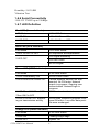
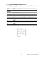
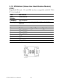
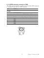
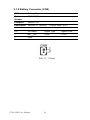
1
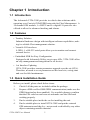
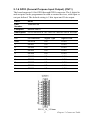
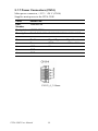
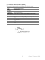
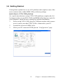
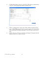
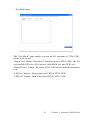
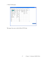
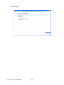
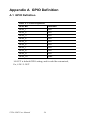
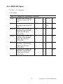
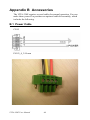
VITA-350E
GPS, GPRS, DI/O, RS232
Automatic Vehicle Location
Device
User Manual
Copyright
This document is copyrighted, © 2008. All rights are reserved. The original manufacturer reserves the right to make improvements to the products described in this manual at any time without notice.
No part of this manual may be reproduced, copied, translated or transmitted in any form or by any means without the prior written permission of
the original manufacturer. Information provided in this manual is
intended to be accurate and reliable. However, the original manufacturer
assumes no responsibility for its use, nor for any infringements upon the
rights of third parties that may result from such use.
Acknowlegement
Microsoft Windows® is a registered trademark of Microsoft Corp.
All other product names or trademarks are properties of their respective
owners.
For more information on this and other Advantech products, please visit
our websites at:
http://www.advantech.com
http://www.advantech.com/eplatform
For technical support and service, please visit our support website at:
http://www.advantech.com/support
This manual is for the VITA-350E.
Part No. 2006A35001
2nd Edition,
Print in China
July 2008
VITA-350E User Manual
ii
Packing List
Before you begin installing your device, please make sure that the following materials have been shipped:
• VITA-350E device
• 1 CD-ROM with User's manual, Advantech Utility
• 1 User’s Manual
• 1 GPS antenna
• 1 GPRS antenna
• 1 Power cable
• 4 Mounting screws
If any of these items are missing or damaged, contact your distributor or
sales representative immediately.
Model No. List
VITA-350E
Description
GPS, GPRS, DI/O and RS232
iii
FCC
This device complies with the requirements in part 15 of the
FCC rules: Operation is subject to the following two conditions:
1.This device may not cause harmful interference, and
2. This device must accept any interference received, including interference that may cause undesired operation
This equipment has been tested and found to comply with the
limits for a Class A digital device, pursuant to Part 15 of the
FCC Rules. These limits are designed to provide reasonable
protection against harmful interference when the equipment
is operated in a commercial environment. This equipment
generates, uses, and can radiate radio frequency energy
and, if not installed and used in accordance with the instruction manual, may cause harmful interference to radio communications. Operation of this device in a residential area is
likely to cause harmful interference in which case the user will
be required to correct the interference at his/her own
expense. The user is advised that any equipment changes or
modifications not expressly approved by the party responsible for compliance would void the compliance to FCC regulations and therefore, the user's authority to operate the
equipment.
Caution!
There is a danger of a new battery exploding if it is incorrectly
installed. Do not attempt to recharge, force open, or heat the
battery. Replace the battery only with the same or equivalent
type recommended by the manufacturer. Discard used batteries according to the manufacturer’s instructions.
根據交通部低功率管理辦法規定:
第十二條
經型式認證合格之低功率射頻電機,非經許可,公司、商號或使用者均不
得擅自變更頻率、加大功率或變更原設計之特性及功能。
第十四條
低功率射頻電機之使用不得影響飛航安全及干擾合法通信;經發現有干擾
現象時,應立即停用,並改善至無干擾時方得繼續使用。前項合法通信,
指依電信規定作業之無線電信。低功率射頻電機須忍受合法通信或工業、
科學及醫療用電波輻射性電機設備之干擾。
VITA-350E User Manual
iv
Additional Information and Assistance
1. Visit the Advantech web site at www.advantech.com where you can
find the latest information about the product.
2. Contact your distributor, sales representative, or Advantech's customer
service center for technical support if you need additional assistance.
Please have the following information ready before you call:
• Product name and serial number
• Description of your peripheral attachments
• Description of your software (operating system, version, application
software, etc.)
• A complete description of the problem
• The exact wording of any error message
v
VITA-350E User Manual
vi
Contents
Chapter
1 Introduction ......................................................2
1.1
1.2
1.3
1.4
1.5
1.6
Introduction ....................................................................... 2
Features ............................................................................. 2
Quick Installation Guide ................................................... 2
GPS Antenna Installation .................................................. 3
GPRS Antenna Installation ............................................... 5
Specifications .................................................................... 6
1.6.1
1.6.2
1.6.3
1.6.4
1.6.5
1.6.6
1.6.7
1.7
GPRS Module Siemens Power Modes ........................... 6
GPS Specifications ......................................................... 6
GSM/GPRS Specifications of Siemens MC55 module.. 7
Programmable Digital I/O .............................................. 7
Enviromental Specifications ........................................... 7
Serial Connectivity ......................................................... 8
LED Definition ............................................................... 8
System Dimensions ........................................................... 9
Figure 1.1:System Outlook Dimensions....................... 10
Chapter
2 Connector Table .............................................12
2.1
Connector Table .............................................................. 12
2.1.1
2.1.2
2.1.3
2.1.4
2.1.5
2.1.6
2.1.7
2.1.8
2.2
Chapter
COM port connector (CN2).......................................... 12
GPS antenna connector (CN3)...................................... 13
SIM Holder (Subscriber Identification Module) (CN5) 14
GPRS antenna connector (CN6) ................................... 15
Battery Connector (CN9).............................................. 16
GPIO (General Purpose Input Output) (CN11) ............ 17
Power Connectors (CN14)............................................ 18
Power Reset button (SW1) ........................................... 19
LED Definition ....................................................................... 20
3 Advantech MRM Utility ................................22
3.1
Introduction & Overview ................................................ 22
3.1.1
3.1.2
3.1.3
3.1.4
3.1.5
3.2
3.3
Overview....................................................................... 22
Installation .................................................................... 23
PC System Requirements.............................................. 23
Installing MRM Utility ................................................. 23
How Does VITA-350E Work? ..................................... 23
Getting Started................................................................. 25
Format of Sending Packets.............................................. 49
Appendix A GPIO Definition .............................................56
A.1
A.2
GPIO Definition .............................................................. 56
GPIO DC Spec. ............................................................... 57
vii
Appendix B Accessories ......................................................60
B.1
Power Cable .................................................................... 60
Appendix C Mechanical Drawing ......................................64
Figure C.1:VITA-350E Mechanical Drawinng ............ 65
VITA-350E User Manual
viii
CHAPTER
1
General Information
This chapter gives background
information on the VITA-350E.
Sections include:
• Introduction
• Features
• Quick Installation Guide
• RF Antenna Installation
• Specifications
• System Dimensions
1
Chapter 1 General Information
Chapter 1 Introduction
1.1 Introduction
The Advantech VITA-350E provides in-vehicle data solutions while
operating over Carrier's GSM/GPRS networks for Fleet Management. A
16-channel GPS module, 1 x RS232 and 9 x digital I/O ports are also
offered to allow for advanced tracking and alarms.
1.2 Features
• Turnkey Solution
Industrial hardware design with intelligent software capabilities, making it a reliable Fleet management solution.
• Versatile I/O Interfaces
9 GPIO, 1 x RS-232 serial ports allow you to monitor and connect
external device.
• Embedded SDK for Easy Configuration
Equipped with Advantech Utility, easy-to-use APIs, VITA-350E offers
an easy management and integration for all devices.
• Air Interface Updating
VITA-350E provides remote parameters upgrade over the air (OTA).
Therefore, no need to re-set parameters on the local site, saving time
and cost for field maintenance.
1.3 Quick Installation Guide
Before you install, please check below items:
1.
Check if all the parts are included within the package.
2.
Prepare a SIM card for GSM/GPRS communication (make sure the
GPRS function has been enabled). Use a mobile phone to confirm
that the PIN code has not been set and make sure the SIM card
working properly.
3.
Find a suitable place inside the car for installing the unit.
4.
Find a suitable place to install VITA-350E and put the external
GPS antenna toward the sky - not covered or shielded by any other
object containing metallic material.
VITA-350E User Manual
2
5.
Check if all the wiring has been connected correctly; connect the
AVL unit to the power source (12 or 24 VDC).
6.
Check all LED indicator blinks regularly to confirm VITA-350E
working status.
7.
Put VITA-350E on a proper space with wall mount kit or strong
adhesive double-sided tape and make sure VITA-350E will sustain
during the vibration or shaking situation.
1.4 GPS Antenna Installation
The antenna must be mounted so it is visible to the sky. The windshield
must be cleaned before antenna is mounted. Ensure that tinted or any metalic objects do not obscure the line of sight.
Step 1: Clean the inside of the windshield.
Step 2: Peel off the adhesive tape cover.
3
Chapter 1 General Information
Step 3: Push the antenna firmly into position.
Note:
Do not mount within the wiper movement arc area.
Do not mount on the tinted area as displayed below.
VITA-350E User Manual
4
Note: The adhesive tape side is the active side and must face the sky.
1.
Make certain to mount in position outside of the wiper blades
movement arc.
2.
Do not mount on the tinted area at the top of some widescreens as
these can contain metal content and may degrade the antenna
sensitivity.
3.
Avoid running the antenna cable next to antenna cables from two
way radios, cell phones etc.
4.
Do not lengthen/shorten the shielded antenna cable.
5.
Route the shielded antenna cable through the ferrite core in order to
minimise radio frequency interference.
6.
Take special care when plugging and unplugging the antenna
connector.
7.
Take care not to place the antenna under a structure such as s metal
Roof Rock.
1.5 GPRS Antenna Installation
The windshield must be cleaned before antenna is mounted&it must be
mounted vertaically and not horizontally.
Note: Any 3rd party transmitting/receiving device can affect the
sensitivity and range of the RF.
1.
Avoid running tha antenna cable next to antenna cables from two
way radios, cell phones etc.
2.
Do not strengthen/shorten the shielded antenna cable.
5
Chapter 1 General Information
3.
Take special care when plugging and unplugging the antenna
connector into the male/female connector.
1.6 Specifications
1.6.1 GPRS Module Siemens Power Modes
Parameter DescriptionCondition
Min Type Max Unit
Power Down Mode
50 100 µA
Sleep mode at DRX=2
4.3
@DRX=5
3.0
mA
@DRX=9
2.5
Average
IDLE mode at DRX=2
supply
I BATT+
EGSM 9001)4)
15
current3)
15
mA
GSM 1800/19002)4)
15
DATA mode GPRS,
(4 Rx, 1Tx) EGSM 9001)4)
300
300
mA
GSM 1800/19002)4)
230
Notes:
1) Power Controll Level PCL 5
2) Power Controll Level PCL 0
3) All average supply currrent values at IVDD =0mA
4) Test condition for the typical values: 50 Ω antenna
1.6.2 GPS Specifications
16 channel ANTARIS 4 positioning
Supports different serial protocols (NEMA, UBX, & RTCM)
Support Active Antenna
Antenna short and open circuit
Power brown-out protection: No external reset hardware needed
Operating temperature range: -40 to 85°C
• Accuracy
Position 2.5m CEP3 5.0m SEP4
Position DGPS/SBAS2 2.0m CEP 3.0m SEP
VITA-350E User Manual
6
• Accuisition5_6
GPS_Mode_(U
BX-CFG_Msg)
Fast
Acquisition
Mode
Normal
Mode
High
Sensitivity
Mode
Auto Mode
Cold Start
34s
36s
41s
34s
Warm Start
33s
N/A
N/A
N/A
Hot Start
<3.5s
N/A
N/A
N/A
Reacquisition
<1s
N/A
N/A
N/A
• Sensitivity7
Tracking -158 dBm
Acquisition & Reacquisition -148 dBm
Cold Starts -142 dBm
1.6.3 GSM/GPRS Specifications of Siemens MC55
module
Tri-band MC55 EGSM900 /GSM1800/1900
GPRS multi-slot Class 10
GPRS mobile station Class B
Download: Max. 85.6 Kbps
Uplink: Max. 42.8 Kbps
Coding Scheme: CS1-4
Internet service: TCP, UDP, HTTP, FTP, SMTP, POP3
1.6.4 Programmable Digital I/O
Digit GPIO: 5 In / 5 Out
VIH: 2.64~3.3V (Input logic 1)
VIL: 0~0.66V (Input logic 0)
VOH: 3.2~3.3V (Output logic 1)
VOL: 0~0.4V (Output logic 0)
Maximum DC current: 5mA
1.6.5 Enviromental Specifications
Operating Temperature:
Storage Temperature:
7
Chapter 1 General Information
Humidity: 5-85% RH
Vibration Test:
1.6.6 Serial Connectivity
1 RS-232 TX/RX up to 230Kbps
1.6.7 LED Definition
Red LED (Power Indicator)
LED Mode
VITA-350E Status
1 LED ON
+12/+24V Power ON
2 LED OFF
+12/+24V Power OFF
Blue LED (GPS Indicator)
LED Mode
VITA-350E Status
1 LED 1s ON / 1s OFF
2D acquisition accomplishment
GPS signal searching
2 LED OFF
GPS don’t work
No GPS signal
Green LED (GPRS Indicator)
LED Mode
VITA-350E Status
1 LED Permanently ON
GPRS Power Down
2 LED 600ms ON/ 600ms OFF
Limited Network Service: No SIM
inserted. No PIN enter. Network
search in progress. Ongoing user
authentication. Network login in
progress.
3 LED 75ms ON/ 75ms OFF/
75ms ON/ 3s OFF
GPRS network activated
4 LED 0.5s ON/ OFF depending on transmission activity
GPRS Data Transfer in progress. LED
goes ON within 1 sec after data packets were exchanged.
Orange LED (Status Indicator)
LED Mode
VITA-350E Status
1 LED ON
Loading image stage
2 LED OFF
System OK
VITA-350E User Manual
8
1.7 System Dimensions
9
Chapter 1 General Information
˚ˣ˦
˚ˣ˥˦
˥˘˦˘˧
˟˘˗
˥˦˅ˆ˅
ˣˢ˪˘˥
˚ˣ˜ˢ
Figure 1.1: System Outlook Dimensions
VITA-350E User Manual
10
CHAPTER
2
Connector Table
This chapter explains the setup
procedures of VITA-350E hardware,
including instructions on connecting
peripherals and indicators. Be sure to
read all safety precautions before you
begin the installation procedure.
11
Chapter 2 Connector Table
Chapter 2 Connector Table
2.1 Connector Table
2.1.1 COM port connector (CN2)
The VITA-350E provides 1 serial ports (COM1: RS-232 TX/RX) in one
DB-9 connector (COM1). You can find the pin assignments for the COM
port connector in Appendix A.
CN2
COM1
Part
Number
1654000056
Footprint
DBCOM-VM5MS
Description D-SUB CON. 9P 90D(M) DIP 070241MR009S200ZU
SUYIN
Pin
Pin Name
1
NC
Signal Type
Signal Level
2
RXD#
IN
+5V
3
TXD#
OUT
+5V
4
NC
5
GND
6
NC
7
NC
8
NC
9
NC
VITA-350E User Manual
12
2.1.2 GPS antenna connector (CN3)
The GPS function needs the expander antenna, and the GPS connector is
a standard Female SMA connector.
CN3
GPS Antenna Con.
Part
Number
1654001599
Footprint
RF-SMAC037
Description RF Conn 5p 180D(F) DIP SMA-C037-G
Pin
Pin Name
1
RF_IN
2
GND
3
GND
4
GND
5
GND
Signal Type
13
Signal Level
Chapter 2 Connector Table
2.1.3 SIM Holder (Subscriber Identification Module)
(CN5)
Supported SIM card +3V, and SIM interface compatible with ISO 7816
IC Card standard.
CN5
SIM Holder
Part
Number
1654000639
Footprint
SIM-WL608C
Description SIM card conn 6p 90D(F)SMD WO/Pb WL608C3M04-TR
Pin
Pin Name
Signal Type
Signal Level
1
SIM_CCVCC
IN
+3V
2
SIM_CCRST
3
SIM_CCCLK
4
GND
5
NC
6
SIM_CCIO
VITA-350E User Manual
14
2.1.4 GPRS antenna connector (CN6)
The GPRS function needs the expander antenna, and the GPRS connector
is a standard Female Reverse SMA connector.
CN6
GPRS Antenna Con.
Part
Number
1700004811
Footprint
CABLE-SMAFN9
Description Coaxial Cable 10cm SMT SMA(F) to I-PEX
Pin
Pin Name
1
GND
2
GND
3
GND
4
GND
Signal Type
15
Signal Level
Chapter 2 Connector Table
2.1.5 Battery Connector (CN9)
CN9
Battery Con.
Part
Number
1655902032
Footprint
WHL2V-125
Description WAFER 2P 180D(M)
1.25mm 53047-0210
Pin
Pin Name
Signal Type
Signal Level
1
BAT_VCC
PWR
+3.3V
2
GND
WB_2V_1.25mm
VITA-350E User Manual
16
2.1.6 GPIO (General Purpose Input Output) (CN11)
The board supports 10-bit GPIO through GPIO connector. The 9 digital in
and out-puts can be programmed to read or control devices, with input or
out-put defined. The default setting is 5 bits input and 5 bits output.
CN11
GPIO
Part
Number
1652000746
Footprint
ME050-35010
Description PLUG-IN BLOCK 10P 90D DIP ME050-35010 WO/PB
Pin
Pin Definition
Signal Type
Signal Level
GND
GPIO10
I/O
+3.3V
1
GPIO1
I/O
+3.3V
2
GPIO2
I/O
+3.3V
3
GPIO3
I/O
+3.3V
4
GPIO4
I/O
+3.3V
5
GPIO5
I/O
+3.3V
6
GPIO6
I/O
+3.3V
7
GPIO7
I/O
+3.3V
8
GPIO8
I/O
+3.3V
9
GPIO9
I/O
+3.3V
PLUG_10_3.50mm
17
Chapter 2 Connector Table
2.1.7 Power Connectors (CN14)
Main power connector, +12 V / +24 V (CN14)
Supplies main power to the VITA-350E.
CN14
Power Con.
Part
Number
1652000744
Footprint
ME050-35004
Description PLUG-IN BLOCK 4P 90D DIP ME050-35004 WO/P
Pin
Pin Name
Signal Type
Signal Level
1
B+
PWR
+12V / +24V
2
ACC
IN
3
GND
4
GND
PLUG_4_3.50mm
VITA-350E User Manual
18
2.1.8 Power Reset button (SW1)
Momentarily pressing the reset button will activate a reset.
SW1
Power Reset Button
Part
Number
1601063200
Footprint
SW-HDK632BR-ST
Description PUSH SW L=5.85mm Reset Button HDK632BR
Pin
Pin Name
1
GND
2
uP_RESET#
3
GND
4
GND
Signal Type
19
Signal Level
Chapter 2 Connector Table
2.2 LED Definition
Red LED (Power Indicator)
LED Mode
VITA-350E Status
1 LED ON
+12/+24V Power ON
2 LED OFF
+12/+24V Power OFF
Blue LED (GPS Indicator)
LED Mode
1 LED 1s ON / 1s OFF
VITA-350E Status
2D acquisition accomplishment
GPS signal searching
2 LED OFF
GPS don’t work
No GPS signal
Green LED (GPRS Indicator)
LED Mode
VITA-350E Status
1 LED Permanently ON
GPRS Power Down
2 LED 600ms ON/ 600ms OFF
Limited Network Service: No SIM
inserted. No PIN enter. Network
search in progress. Ongoing user
authentication. Network login in
progress.
3 LED 75ms ON/ 75ms OFF/
75ms ON/ 3s OFF
GPRS network activated
4 LED 0.5s ON/ OFF depending on transmission activity
GPRS Data Transfer in progress. LED
goes ON within 1 sec after data packets were exchanged.
Orange LED (Status Indicator)
LED Mode
VITA-350E Status
1 LED ON
Loading image
2 LED OFF
System OK
VITA-350E User Manual
20
CHAPTER
3
Advantech MRM Utility
Advantech MRM Utility software is a
comprehensive, flexible human
machine interface application environment, which supports the functions to
customize MRM applications in the
Windows XP, and Windows CE environment. MRM Utility software provides a windows-based, mouse driven
system to identify AVL Data and GPS
Tracking System.
Sections include:
• Introduction
• Getting Started
• Format of Sending Packets
21
Chapter 3 Advantech MRM Utility
Chapter 3 Advantech MRM Utility
3.1 Introduction & Overview
Introduction & Overview gives a general background to the AVL platform. The system architecture is explained, and the product’s main features are introduced. Installation of the software is explained.
3.1.1 Overview
Congratulations on your purchase of Advantech’s VITA-350E product for
developing MRM control for GPS and automation solutions of industry.
Advantech VITA-350E product is a comprehensive, flexible GPS and
GPRS enabled controlling platform that supports the functions and utilities to develop automation applications in industry environment. VITA350E products provide GPS/GPRS enabled systems including remote
controlling & accessing functions to be connected to Internet/Intranet.
VITA-350E is extremely flexible and easy to use. The client could use
MRM Utility to get/set the information of devices. A VITA-350E device
will be automatically probed and shown on your Utility screen. After setting the server IP address, port and sending format of data, VITA-350E
will automatically connect to the server and send GPS or I/O data to the
server.
The VITA-350E kernel is a multi-threaded engine for optimal performance. It provides you GPS/GPRS connectivity with your mobile
machines including cars, fleets, and other automated devices. It saves a
lot of effort and time when developing your applications. The VITA-350E
platform ensures that you can integrate your process data into existing
AVL information systems.
In addition, VITA-350E MRM Utility software utility leverages 32-bit
Windows’ preemptive multi-tasking capability to support Windows CE
environments.
Contents
• Installation
• How does VITA-350E work?
VITA-350E User Manual
22
3.1.2 Installation
MRM Utility engine is built-in on VITA-350E platform. So you don’t
install anything in the VITA-350E product.
MRM Utility on Windows XP is the client for configuring and controlling
VITA-350E remotely, you must copy and execute it into a PC system.
3.1.3 PC System Requirements
• OS : Microsoft Windows XP
• RAM : at least 128 MB memory
• Disk space: at least 4 MB space
• CPU: Intel Pentium II processor 400 MHz or higher
• Display: VGA resolution or higher
• Microsoft-compatible mouse
• Ethernet port
3.1.4 Installing MRM Utility
Advantech MRM utility ships with an execution program and you just
copy the program to your computer.
3.1.5 How Does VITA-350E Work?
VITA-350E platform includes two parts: controlling engine and client
utility. The controlling engine is the hardware body plus MRM program
softwares. VITA-350E device has one RS485 port and can be connected
by your PC-based system. If GPS and DIO data of the connected devices
are periodic, you could send the data on VITA-350E device to your
server..
VITA-350E platform is designed to fit the following purposes:
• GPS/GPRS automation system
• Data acquisition provider and access controllers through GPRS
• Enable data to Internet
• Provide remote accessing control
• Easy to configure connected controllers
The MRM utility is the client to configure and control the VITA-350E
platform. The UI is the following:
23
Chapter 3 Advantech MRM Utility
VITA-350E User Manual
24
3.2 Getting Started
Getting Start explains how to use AVL platform and complete some of the
most common tasks within MRM Utility software package.
Quick Start to VITA-350E platform
As a quick introduction to using VITA-350E platform, complete the following procedure to run VITA-350E and MRM utility that was copied to
your computer’s hard disk drive during the software installation.
1.
Power on the VITA-350E, plug-in COM port modem cable connector to it and be sure that VITA-350E is connected to your PC.
2.
Launch the Advantech MRM utility.
3.
Select your PC connected COM port on “Configuration” page.
25
Chapter 3 Advantech MRM Utility
4.
Click on the button “Search”, the VITA-350E device connected on
your PC will be probed and linked automatically.
5.
Select “Configuration” page again. This window includes set/get
time, GSM/GPRS options, screen emulator quality, ACC power off
delay, platform ID number and name, server IP, port, and send format.
6.
Define your server IP, port and data send format. Then press the Set
button on the Server Option Group.
VITA-350E User Manual
26
7.
Reboot the VITA-350E, then the data will be sent to your specified
server.
The build-in functions shipped with VITA-350E can help you to accomplish some basic controlling data format. You can also change your own
data format which will be described in Chapter 3, “Format of Sending
Packets”.
The following sections overview the basic functions for customizing your
MRM solutions with VITA-350E.
27
Chapter 3 Advantech MRM Utility
• Command Page
There are 4 groups on the tab page: “Command Data”, “GPS Received
Data”, “GSM/GPRS Received Data”, and “AVL Platform Information”.
“Search” button in the “Command Data” group : Search the VITA-350E
device on the serial port cable.
“Clear” button in the “Command Data” group : Clear the command list
data.
“Command Data” list : Show the VITA-350E status list.
“Open” button in “GPS Received Data” group : Open the GPS port.
“Close” button in “GPS Received Data” group : Close the GPS port.
“Clear” button in “GPS Received Data” group : Clear the GPS Received
data list.
“GPS Received Data” list : Show the VITA-350E GPS data.
“Open” button in “GSM/GPRS Received Data” group : Open the GSM
port while GSM mode set to AT-Command mode.
“Close” button in “GSM/GPRS Received Data” group : Close GSM port
while GSM mode set to AT-Command mode.
VITA-350E User Manual
28
“Clear” button in “GSM/GPRS Received Data” group : Clear the GSM/
GPRS Received data list.
“GSM/GPRS Received Data” list : Show the VITA-350E GSM data.
“Product ID” static text in AVL platform information group : Platform
name and should be “VITA-350E”.
“OS version” static text in AVL platform information group : OS version
and got from VITA-350E.
“Bootload Version” static text in AVL platform information group : Bootloader version and got from VITA-350E.
“Firmware Version” static text in AVL platform information group : AVL
engine version and got from VITA-350E.
29
Chapter 3 Advantech MRM Utility
• Screen Emulator page
You can change the screen emulator quality on “configuration” page. The
default quality value is 5 %.
“Get Screen” button : Get the current screen of VITA-350E. The default
size of screen width is 320, and the default size of screen height is 240.
“Start Control” button : Begin controlling the VITA-350E by mouse and
keyboard. After pressing the button, the name of the button will change to
“Disable Control”.
VITA-350E User Manual
30
“Disable Control” button : Stop controlling the VITA-350E by mouse and
keyboard.
“Keyboard Input” edit : Keyboard input field. Input characters will be
sent to VITA-350E.
31
Chapter 3 Advantech MRM Utility
• Configuration page
This page is the main settings page for VITA-350E. These values will be
got first when the VITA-350E is searched. There are several groups in
this page. These groups include “Host Serial Port”, “Device Date/Time”,
“GSM/GPRS Options”, “GPRS Baud Rate”, “COM Baud Rate”, “H/W
Reset”, “Screen Emulator Quality”, “ACC Power Off Delay”, “Platform
Options”, “Voltage Source”, and “Server Options”.
“Host Serial Port” combo-box : Assign the PC connected COM port ID.
All available serial ports will be a item in this list. You should select a
available serial port and connect VITA-350E with this port.
“Get Time” button in the “Device Date/Time” group : Get the current
time from VITA-350E.
“Set Time” button in the “Device Date/Time” group : Set the PC current
time to VITA-350E.
“GSM Mode” combo-box in “GSM/GPRS Options” group : Select the
AT-command or GPRS mode for GSM module. If the mode is set to
GPRS, AVL engine will automatically connect the AP station with specified APN, phone number. If the mode is set to AT-command, the AVL
engine will open the GSM module port with specified baud rate.
VITA-350E User Manual
32
“Baud Rate” combo-box in “GSM/GPRS Options” group : Select a baud
rate for GSM module. It is only used on AT-command mode.
“APN” edit in “GSM/GPRS Options” group : Specify the APN name
when GPRS mode is selected. The default value is “internet”.
“Phone Number” edit in “GSM/GPRS Options” group : Specify the
phone number when GPRS mode is selected. The default is “*99***1#”.
“Set” button in “GSM/GPRS Options” group : Set GSM/GPRS options to
VITA-350E.
“GPS Baud Rate” combo-box in “GPS Baud Rate” group : Define the
baud rate of GPS module. This is fixed and should not be change by user.
“COM Baud Rate” combo-box in “COM Baud Rate” group : Define the
baud rate of VITA-350E COM module. This COM via VITA-350E is
connected and defined by user.
“Reboot” button in “H/W Reset” group : Reboot the VITA-350E device.
“Screen Emulator Quality” edit in “Screen Emulator Quality” group :
Define the screen quality percent when getting screen option enabled.
The range of the value is from 1 % to 100 %.
“Set” button in “Screen Emulator Quality” group : Set specified screen
quality to VITA-350E.
“ACC Power Off Delay” edit in “ACC Power OFF Delay” group : Define
the delay seconds when the ACC power turned off.
“Get” button in “ACC Power OFF Delay” group : Get the ACC power off
delay seconds from VITA-350E.
“Set” button in “ACC Power OFF Delay” group : Set the ACC power off
delay seconds to VITA-350E.
“Type” combo-box in “Platform Options” group : Set the type of VITA350E. The current available items are “Standard Platform” and “Customized platform”. The Standard Platform is specified by Advantech and the
data format is binary. The Customized Platform is specified by user and
33
Chapter 3 Advantech MRM Utility
the data format is text. The data format could be changed by users. The
default type is Customized Platform.
“ID number” edit in “Platform Options” group : Define the ID number of
VITA-350E. This text will be sent to server when the format included the
string <ID>.
“ID name” edit in “Platform Options” group : Define the ID name of
VITA-350E. This text will be sent to server when the format included the
string <TYPE>.
“Set” button in “Platform Options” group : Set the ID number and Name
to VITA-350E.
“Get” button in “Platform Options” group : Get the ID number and Name
from VITA-350E.
“Voltage Source” static text in “Voltage Source” group : Show the Voltage Source. The value should be “12V” or “24V”.
“Get” button in “Voltage Source” group : Get the Voltage Source from
VITA-350E.
“First IP Address” edit text in “Server Options” group : Define the first
server IP address. The VITA-350E will send data to the first server periodically.
“First IP Port Number” edit text in “Server Options” group : Define the
first server socket port number.
“Second IP Address” edit text in “Server Options” group : Define the second server IP address. The VITA-350E will send data to the senond
server when the first server is unconnected.
“Second IP Port Number” edit text in “Server Options” group : Define the
second server socket port number.
“Send Format” edit text in “Server Options” group : Define the format of
data sent to the server. The format descriptions are documented in Chapter 3. The default format is $,<TYPE>,<ID>,<FIX>,<DDMMYY>,<HHMMSS>,<RMC(4)><RMC(3)>,<RMC(6)><RMC(5)>,<SP
EED>,<ANGLE>,0,#<CR><LF>
“Interval Time” edit text in “Server Options” group : Define the interval
seconds between dada packets. The default value is 30 seconds.
“Re-Send Head String” edit text in “Server Options” group : Define the
re-send data head string. When the server is disconnected or GPRS is
VITA-350E User Manual
34
failed, the sent-data will be saved in the VITA-350E internal memory. If
the server is connected, then the unsent data will be sent again. The ReSend Head string is defined to replace the normal send-head string when
the re-send process happened. For example, if the Re-Send Head string is
“$@”, then the re-sent data head will be changed from “$,”to “$@”.
“Set°” button in “Server Options” group : Set server options to VITA350E.
“Get” button in “Server Options” group : Get server options from VITA350E.
35
Chapter 3 Advantech MRM Utility
• GPIO Setting page
The “GPIO Setting” Page enables you to define and get the GPIO directions and values from/to VITA-350E remotely. There are 9 GPIO pins in
VITA-350E. Every GPIO pin could be set to input or output.
“GPIO Direction #n” radio button in “GPIOs Direction/Value” group :
Specify the direction of GPIO #n where n is from 1 to 9.
“GPIO Value #n” combo-box in “GPIOs Direction/Value” group : Specify the output value of GPIO pin #n when the direction of the pin defined
to output.
“GPIO Status #n” picture in “GPIOs Status” group : Show the current status of GPIO pin #n.
“Setup” button in “GPIOs Direction/Value” group : Setup directions and
values of GPIO pins to VITA-350E.
“Get” button in “GPIOs Direction/Value” group : Get directions and values of GPIO pins from VITA-350E.
“Refresh” button in “GPIOs Status” group : Get the values of GPIO pins
from VITA-350E.
VITA-350E User Manual
36
• Query GPS page
The “Query” Page enables that you query GPS data from VITA-350E in
specified time range.
“Begin Date” date selector : Select begin date of GPS data in VITA-350E.
“Begin Time” time selector : Select begin time of GPS data in VITA350E.
“End Date” date selector : Select begin date of GPS data in VITA-350E.
“End Time” time selector : Select begin time of GPS data in VITA-350E.
“Save to File” edit text : Specify the filename to save the query GPS data.
“Query from VITA-350E” button : Start querying the GPS data with
specified dates and times.
“Browse” button : Browse the folder and select the path and file to save
queried GPS data.
37
Chapter 3 Advantech MRM Utility
VITA-350E User Manual
38
• Upgrade Firmware page
This “Upgrade Firmware” page enables that you could upgrade the AVL
firmware engine to VITA-350E.
“Upgrade File” edit text : Specify the firmware file. It should include the
file path and filename.
“Version” static text : Show the firmware version for upgrading firmware.
“Check sum” static text : Show the checksum for upgrading firmware.
“Browse” button : Browse the folder and select a path and file to upgrade
to VITA-350E. This upgrade firmware file should be named as MRMagent.bin. There is a file named MRMagent.ver in the same folder.
39
Chapter 3 Advantech MRM Utility
“Upgrade to VITA Device” button : Start upgrading specified firmware to
VITA-350E.
The upgrade procedure is the following:
1.
Power-on VITA-350E device.
2.
Connect your PC to VITA-350E with COM port by Modem cable.
3.
Choose your PC COM port on Configuration Page in MRM utility.
VITA-350E User Manual
40
4.
Press the Search Button on the Command Page
VITA-350E information will be read to your PC.
41
Chapter 3 Advantech MRM Utility
5.
Go to the Upgrade Firmware page in MRM utility and press the
Browse button to select the latest firmware.
VITA-350E User Manual
42
6.
The upgrading firmware information will be shown on the screen,
then press the button “Upgrade to VITA Device”.
7.
Change the tab-page to “Command Page”, you will read the string
“DOC_CMD_WRITEFILE Cmd begin”.
43
Chapter 3 Advantech MRM Utility
8.
Wait about 30 seconds, you will read the strings “UpgradeUtyCmd
begin...” and “UpgradeUtyCmd Success!”.
9.
Now upgrading firmware is successful, then you need to re-boot the
VITA-350E to run new firmware.
10.
After you re-boot the VITA-350E, please check the “AVL Firmware Version” is the same with your firmware version.
VITA-350E User Manual
44
• Test Mode page
The “Test Mode” page enables you test the I/O functions of VITA-350E
device work or not.
“Begin Test” button : Start the I/O functions test for VITA-350E. The I/O
tests include GPS test, SD Card test, flash ROM test, and GPIO test.
“Reset Device” button : Reset the VITA-350E and set default parameters
to it.
“LED On” button : Turn on the error LED of VITA-350E.
“LED Off” button : Turn ff the error LED of VITA-350E.
45
Chapter 3 Advantech MRM Utility
VITA-350E User Manual
46
• Data Format page
This page lets you see the fields of GPS data.
47
Chapter 3 Advantech MRM Utility
• About page
VITA-350E User Manual
48
3.3 Format of Sending Packets
Format of Sending Packet explains the string format for different data
fields. In this chapter, you could learn the format usage about AVL data
fields.
This chapter shows you how to format data sent by VITA-350E. Firstly,
you must design the fields of data received to your server. Your server
should have the capacity to process the data which sent normally or resent abnormally from VITA-350E. Secondly, you could transfer data
fields from raw data to format identifiers of VITA-350E.
The format identifiers supported by VITA-350E are list as follows:
Identifier
Data String
Description
Example
<ID>
ssss
Platform ID
Number
001
<TYPE>
ssss
Platform Type
Name
Advantech
<PACKET>
9999
Packet number
from system
starting.
20
<FIX>
a
Status (A=valid,
V=invalid,
R=unavailable)
A
<GPIO>
XXX
GPIO Status
3F2
<LASTFIXDATE>
DDMMYY
UTC Date for last
valid RMC data.
281107
<LASTFIXTIME>
HHMMSS
UTC Time for last
valid RMC data.
205950
<LASTFIXLONX>
SDDDMM.mm
mm
Longitude for last
valid RMC data.
S is (-) for West
12145.1214
-12001.2589
<LASTFIXLONY>
SDDMM.mmm
m
Latitude for last
valid RMC data.
S is (-) for South
1245.1214
-1201.2589
<SPEED>
999
Speed, the unit is
km/hr
90
<ANGLE>
999
Angle, the unit is
the degree
25
49
Chapter 3 Advantech MRM Utility
<CR>
0x0D
Carriage
Character
0x0D
<LF>
0x0A
Linefeed
Character
0x0A
<STATUS>
x
The status of
VITA-350E.
2:Normal
5:ACC Power off
5
<DDMMYY>
DDMMYY
UTC Date
Value is from
RMC valid or
RTC of VITA350E.
281107
<YYMMDD>
YYMMDD
UTC Date
Value is from
RMC valid or
RTC of VITA350E.
071128
<YYYYMMDD>
YYYYMMDD
UTC Date
Value is from
RMC valid or
RTC of VITA350E.
20071128
<HHMMSS>
HHMMSS
UTC Time.
Value is from
RMC valid or
RTC of VITA350E.
205950
<RMC(1)>
HHMMSS.sss
UTC Time
205950.000
<RMC(2)>
a
Status (A=valid,
V=invalid)
A
<RMC(3)>
DDMM.mmmm
Latitude
1825.4523
<RMC(4)>
d
Direction
(N:north,S:south)
N
<RMC(5)>
DDDMM.mmm
m
Longitude
12145.1214
<RMC(6)>
d
Direction
(E:east,W:west)
E
<RMC(7)>
z.z
Speed over
ground (knots).
63.52
VITA-350E User Manual
50
<RMC(8)>
y.y
Course over
ground (reference
to true north).
240.31
281107
<RMC(9)>
DDMMYY
UTC date
<RMC(10)>
d.d
(Null) or Magnetic variation
(degrees)
<RMC(11)>
v
(Null) or Variation
sense (E=east,
W=west)
<GGA(1)>
HHMMSS.sss
UTC Time
205950.000
<GGA(2)>
DDMM.mmmm
Latitude
1825.4523
<GGA(3)>
d
Direction
(N:north,S:south)
N
<GGA(4)>
DDDMM.mmm
m
Longitude
12145.1214
<GGA(5)>
d
Direction
(E:east,W:west)
E
<GGA(6)>
q
GPS quality
indicator
(0 - Fix not available, or invalid
1 - GPS SPS
Mode, fix valid
2 - Differential,
GPS SPS Mode,
fix valid
3 - GPS PPS
Mode, fix valid)
1
<GGA(7)>
ss
Number of satellities in use (in
tracking),ss=0..12
05
<GGA(8)>
h.h
Horizontal dilution
of precision
h.h : HDOP
2.0
<GGA(9)>
a.a
Antenna altitude
re: mean-sealevel (geoid)
59.0
<GGA(10)>
M
Units of antenna
altitude, meters
M
51
Chapter 3 Advantech MRM Utility
<GGA(11)>
(Null)
Geoidal separation (Not supported)
<GGA(12)>
(Null)
Units of geoidal
separation (Not
yet supported)
<GGA(13)>
x.x
Age of Differential
GPS data(NULL)
<GGA(14)>
xxxx
Differenttial reference station ID
<GSA(1)>
a
Mode:
A- Automatic
M - Manual
(forced to
operate in 2D or 3
D mode)
A
<GSA(2)>
x
Mode:
1 = Fix not
available
2 = 2D
3 = 3D
1
<GSA(3)>
s
1 PRN number of
satellites used in
solution (NULL
for unsued fields)
<GSA(4)>
s
2 PRN number of
satellites used in
solution (NULL
for unsued fields)
<GSA(5)>
s
3 PRN number of
satellites used in
solution (NULL
for unsued fields)
<GSA(6)>
s
4 PRN number of
satellites used in
solution (NULL
for unsued fields)
<GSA(7)>
s
5 PRN number of
satellites used in
solution (NULL
for unsued fields)
VITA-350E User Manual
52
<GSA(8)>
s
6 PRN number of
satellites used in
solution (NULL
for unsued fields)
<GSA(9)>
s
7 PRN number of
satellites used in
solution (NULL
for unsued fields)
<GSA(10)>
s
8 PRN number of
satellites used in
solution (NULL
for unsued fields)
<GSA(11)>
s
9 PRN number of
satellites used in
solution (NULL
for unsued fields)
<GSA(12)>
s
10 PRN number
of satellites used
in solution (NULL
for unsued fields)
<GSA(13)>
s
11 PRN number
of satellites used
in solution (NULL
for unsued fields)
<GSA(14)>
s
12 PRN number
of satellites used
in solution (NULL
for unsued fields)
<GSA(15)>
p.p
PDOP
<GSA(16)>
h.h
HDOP
<GSA(17)>
v.v
VDOP
<GLL(1)>
DDMM.mmmm
Latitude
1825.4523
<GLL(2)>
d
Direction
(N:north,S:south)
N
<GLL(3)>
DDDMM.mmm
m
Longitude
12145.1214
<GLL(4)>
d
Direction
(E:east,W:west)
E
<GLL(5)>
HHMMSS.sss
UTC Time
205950.000
53
Chapter 3 Advantech MRM Utility
<GLL(6)>
a
Status (A=valid,
V=invalid)
<VTG(1)>
t.t
Course Over
Ground (degrees
True)
0 if over current
DOP mask
<VTG(2)>
T
Units: T - degrees
True
<VTG(3)>
m.m
Course Over
Ground (degrees
Magnetic)
0 if over current
DOP mask
<VTG(4)>
s.s
Speed (knots).
0 if over current
DOP mask
<VTG(5)>
N
Units: N ®C knots
<VTG(6)>
g.g
Speed (Km/hr).
0 if over current
DOP mask
<VTG(7)>
K
Units: K - Km/hr
A
For examples,
$,<TYPE>,<ID>,<FIX>,<DDMMYY>,<HHMMSS>,<RMC(4)><RMC(3)>,<RMC(6)><RMC(5)>,<SP
EED>,<ANGLE>,0,#<CR><LF>
VITA-350E User Manual
54
Appendix
A
GPIO Definition
The VITA-350E is equipped with a
watchdog timer that resets the CPU or
generates an interrupt if processing
comes to a standstill for any reason.
This feature ensures system reliability
in industrial standalone or unmanned
environments.
55
Appendix A GPIO Definition
Appendix A GPIO Definition
A.1 GPIO Definition
Table A.1: GPIO Definition
GPIO No.
Function
GPIO_1
OUT
GPIO_2
OUT
GPIO_3
OUT
GPIO_4
OUT
GPIO_5
OUT
GPIO_6
OUT
GPIO_7
OUT
GPIO_8
OUT
GPIO_9
OUT
GPIO_10
GND
10 OUT is default GPIO setting, and it could be customized,
Ex, 4 IN / 5 OUT.
VITA-350E User Manual
56
A.2 GPIO DC Spec.
VCCQ: 3.3V (Typical)
VSS: GND
Table A.2: Output DC Operating Conditions
VOH
Output High Voltage, all
standard output and I/O
pins
VCCQ-0.1
VCCQ
V
VOL
Output Low Voltage, all
standard output and I/O
pins
VSS
VSS+
0.4
V
IOH_H
Output High Current, all
standard, high-strength
output and I/O pins
(VO=VOH)
-10
mA
IOH_L
Output High Current, all
standard, low-strength
output and I/O pins
(VO=VOH)
-3
mA
IOL_H
Output Low Current, all
standard, high-strength
output and I/O pins
(VO=VOH)
10
mA
IOL_L
Output Low Current, all
standard, low-strength
output and I/O pins
(VO=VOH)
3
mA
57
Appendix A GPIO Definition
VITA-350E User Manual
58
Appendix
B
Accessories
59
Appendix B Accessories
Appendix B Accessories
The VITA-350E requires several cables for normal operation. You can
make them yourself or purchase an optional cable kit assembly, which
includes the following.
B.1 Power Cable
CN15
PLUG_4_3.50 mm
VITA-350E User Manual
60
PIN1: Power Input, Red line, 12 V / 24 V Car Battery DC constant Input.
PIN2: ACC, Yellow line, Ignition/Switching power, see the related
operating power at notes3.
PIN3: GND, Black line, ground,
Notes:
1. The length of Power cable is 3 M.
2. Power Input Voltage 9~35 V.
3. Power Operating Voltage 10~30 V (9 V would be looked as battery
low).
61
Appendix B Accessories
VITA-350E User Manual
62
Appendix
C
Mechanical Drawings
63
Appendix C Mechanical Drawing
Appendix C Mechanical Drawing
C.1 Mechanical Drawing
VITA-350E User Manual
64
˚ˣ˦
˚ˣ˥˦
˥˘˦˘˧
˟˘˗
˥˦˅ˆ˅
ˣˢ˪˘˥
˚ˣ˜ˢ
Figure C.1: VITA-350E Mechanical Drawinng
65
Appendix C Mechanical Drawing
VITA-350E User Manual
66


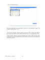
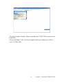
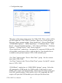
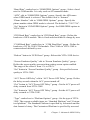
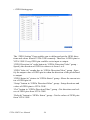
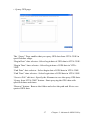
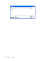
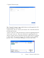
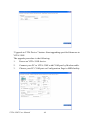


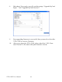


![[PDF:4.7MB]](http://vs1.manualzilla.com/store/data/005853887_1-c5fd0ffcec21d199ddeaa4c471851be4-150x150.png)
![[PDF:3.6MB]](http://vs1.manualzilla.com/store/data/005700359_1-411bc916f99a59f282120c6ff0bb3aea-150x150.png)
![[PDF:1.8MB]](http://vs1.manualzilla.com/store/data/005708629_1-c6bdf3b3035e2fb2adedb53e84bf3717-150x150.png)