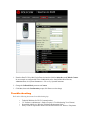
1
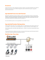
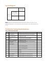
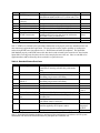
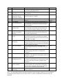
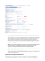
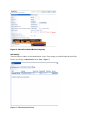
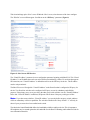
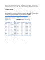
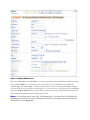
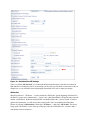
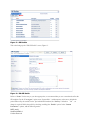
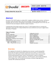
I n n o v a t i o n N e t w o r k A p p N o t e IN- 13050 Date: November, 2013 Product: Spectralink 8400 Series Wireless Handsets System version: ShoreTel 14.1 Abstract This application note provides the details on adding the Spectralink 8400 Series Wireless Handsets to the ShoreTel® IP Phone system. ShoreTel tests and validates the interoperability of the Member's solution with ShoreTel's published software interfaces. ShoreTel does not test, nor vouch for the Member's development and/or quality assurance process, nor the overall feature functionality of the Member's solution(s). ShoreTel does not test the Member's solution under load or assess the scalability of the Member's solution. It is the responsibility of the Member to ensure their solution is current with ShoreTel's published interfaces. The ShoreTel Technical Support organization will provide Customers with support of ShoreTel's published software interfaces. This does not imply any support for the Member's solution directly. Customers or reseller partners will need to work directly with the Member to obtain support for their solution. Table of Contents Overview ..................................................................................................................................................................................... 3 Spectralink Overview and Contact ............................................................................................................................................ 3 Spectralink Product Information ................................................................................................................................................ 3 Architecture Overview................................................................................................................................................................ 3 Version Support .......................................................................................................................................................................... 4 Certification Testing Results Summary ..................................................................................................................................... 4 Table 1: Basic Feature Test Cases ........................................................................................................................................ 4 Table 2: Extended Feature Test Cases.................................................................................................................................. 5 Configuration Overview ............................................................................................................................................................. 7 ShoreTel Configuration .............................................................................................................................................................. 7 ShoreTel System Settings - General ...................................................................................................................................... 7 Call Control Settings .............................................................................................................................................................. 7 Switch Settings - Allocating Ports for SIP Extensions ......................................................................................................... 8 Site Settings........................................................................................................................................................................... 10 Creating SIP Extension ........................................................................................................................................................ 12 Figure 9 – Adding/Editing Users ......................................................................................................................................... 13 Figure 10 – Individual User SIP Settings ............................................................................................................................ 14 SIP Profiles............................................................................................................................................................................ 14 Figure 11 – SIP Profiles ....................................................................................................................................................... 15 Figure 12 – Edit SIP Profile ................................................................................................................................................. 15 Spectralink 8400 Handset Configuration ................................................................................................................................ 16 Spectralink 8400 Phone Settings – Phone User Interface .................................................................................................. 16 Spectralink 8400 Settings – Web Configuration Utility .................................................................................................... 17 Troubleshooting ........................................................................................................................................................................ 18 Spectralink Technical Support ................................................................................................................................................. 19 Document Feedback ................................................................................................................................................................. 19 Document and Software Copyrights........................................................................................................................................ 19 Trademarks ................................................................................................................................................................................ 19 Disclaimer.................................................................................................................................................................................. 20 Company Information............................................................................................................................................................... 20 Overview The document focuses on the configuration procedures needed to set up the Spectralink 8400 Series Wireless Handsets for the ShoreTel system and the configuration needed on the ShoreTel system to support the Spectralink 8400 handsets. Spectralink Overview and Contact Spectralink, a global leader in wireless solutions, solves the everyday problems of mobile workers through technology, innovation and integration that enable them to do their jobs better. By constantly listening to how customers move through their workdays, Spectralink is able to develop reliable, enterprise-grade voice and data solutions and deliver them through a powerful, durable device For more information, please visit www.spectralink.com or call 800-775-5330. Spectralink Product Information The Spectralink® 8400 VoWLAN series handsets deliver on a fundamental need for enterprise-grade on-site voice mobility. Characterized by market-leading HD Voice™ quality, durability and broad telephony and WLAN interoperability, Spectralink 8400 handsets deliver a reliable user experience and predictable return on investment. The Spectralink 8400 series enhances the customer value proposition through an optional integrated barcode scanner and an enhanced standards-based applications interface. Architecture Overview Application Server 802.11 a/b/g/n WLAN Spectralink 8400 Series Handsets Version Support Spectralink 8400 Series 4.2.1.003 ShoreTel Release 13.2 (build 18.42.1304.0 and above) ü 14.1 ü Note: Deployment of Spectralink 8400 handsets require ShoreTel SIP Device License(s) (one per Spectralink 8400 handset) as well as the either the Extension & Mailbox License OR the Extension Only License Certification Testing Results Summary Table 1: Basic Feature Test Cases ID Name Description 1.1 Verify successful startup and initialization of the device up to a READY/IDLE state using a static IP address Verify successful re-initialization of device after power loss while device is idle Verify successful startup and initialization of the device up to a READY/IDLE state using DHCP Verify successful re-initialization of device after power loss while device is idle Verify the ability to set Diffserv Code Point from SIP DUT (device under test) Verify setting of Date and Time Update on SIP DUT 1.7 Device initialization with static IP address Device reset – idle (for static configurations) Device initialization with DHCP Device reset – idle (for dynamic configurations) Verify Diffserv Code Point support Verify Date and Time Update support Place call 1.8 Receive call 1.9 Place call - redial 1.10 Place call – speed dial 1.11 CODEC support (DUT to ShoreTel Phone) CODEC support (DUT to SIP reference) 1.2 1.3 1.4 1.5 1.6 1.12 Verify successful call placement with normal dialing to a variety of terminating phones Verify successful call placement with normal dialing to a variety of terminating phones Verify successful call placement using re-dial to SIP Reference Verify successful call placement using programmed speed dial Verify successful call connection and audio path using all supported CODECs (G.711-Ulaw and G.729) Verify successful call connection and audio path using all supported CODECs (G.711-Ulaw and G.729) Results Pass Pass Pass Pass Not Tested Pass Pass Pass Pass Pass Pass Pass ID Name Description Results 1.13 CODEC negotiation Pass 1.14 Hold DUT to SIP reference Hold DUT to ShoreTel Forward Forward from SIP DUT Mute Out-of-band/ In-band DTMF Transmission Verify successful negotiation between devices configured with different default CODECs (G.711-Ulaw and G.729) Verify successful hold and resume of connected call Verify successful hold and resume of connected call Verify successful forwarding of incoming calls Verify successful forwarding of incoming calls Verify device’s mute function Verify successful transmission of in-band and out-ofband digits (RFC2833) for calls placed to and from the DUT with a variety of other devices Verify that device notifies the user about missed calls Verify the device’s volume adjustment function Pass Pass Pass Pass Pass Note-1 1.15 1.16 1.17 1.18 1.19 1.20 1.21 Missed call notification Volume Pass Pass Pass Note 1: DTMF tones initiated by the Spectralink 8400 handsets work properly with Auto Attendant menus and other automated equipment that require tones. The test plan also tests the phones capability of sending tones and receiving DTMF tones from other devices (i.e. ShorePhones and other SIP endpoints). The Spectralink 8400 handsets properly send DTMF tones to the other devices and are heard by the remote device, but when the Spectralink is receiving tones from these devices it does not play the tone to the user. Since we can think of no application that would be affected by this we marked it as a passed test case. Table 2: Extended Feature Test Cases ID Name Description Notes 3.1 Call waiting Pass 3.2 3.3 Park Extended forward 3.4 Extended forward from SIP DUT Transfer – blind Transfer – monitored Conference – ad hoc Verify appropriate notification and successful connection of incoming call while busy with another party Verify successful park and retrieval of connected call Verify extended call forwarding options – busy forwarding, ring no answer forwarding Verify extended call forwarding options – busy forwarding, ring no answer forwarding Verify successful blind transfer of connected call Verify successful monitored transfer of connected call Verify successful ad hoc conference of three parties 3.5 3.6 3.7 3.8 3.9 3.10 Place call – secondary line Receive call – secondary line Callback 3.11 Headset 3.12 Ring selection Verify successful call placement using secondary line Verify successful connection of incoming call on secondary line Verify successful connection of a call using the missedcall callback feature of the device Verify the device’s support for external headsets (using headsets supplied by the 3P phone vendor) Verify the device’s ability to change the ring type Pass Pass Pass Pass Pass Pass Note-2 Pass Pass Pass Not Tested Supported by DUT Pass Note 2: Spectralink 8400 handsets default to a maximum of three participants to a conference call. The system administrator can increase the maximum number of participants to a conference call. ID 3.13 Name Caller ID 3.14 3.16 SIP Device Generates Busy Tone POTS Analog Gateway supports the transfer operation by “flashing” 911 3.17 3.18 Fax Handling Auto Attendant Menu 3.19 Auto Attendant Menu “Dial by Name” 3.20 Auto Attendant Menu checking Voice Mail mailbox Initiate call to a Hunt Group 3.15 3.21 3.22 Initiate call to a Workgroup 3.23 Hunt Group Member 3.24 Workgroup Agent 3.25 Call Forward – “FindMe” 3.26 ShoreTel Converged Conferencing Server 3.27 Bridged Call Appearance (BCA) extension 3.28 Additional Phones (Simulring) Description Verify that Caller ID name and number is sent and received from SIP endpoint device Verify that SIP DUT generates busy tone when calling a busy extension Verify that the POTS Analog Gateway can support the transfer operation by “flashing” Notes Pass Verify dialing “911” on DUT could connect with “911” services Verify that fax can be sent and received through DUT Verify that DUT can initate calls properly to a ShoreTel Auto Attendant menu and that you can transfer to the desired extension. Verify that DUT can initiate calls properly to a ShoreTel Auto Attendant menu and that you can transfer to the desired extension using the “Dial by Name” feature. Verify that DUT can initiate calls properly to a ShoreTel Auto Attendant menu and that you can transfer to the Voice Mail Login Extension. Initiate a call from DUT and verify that calls route to the proper Hunt Group and are answered by an available hunt group member with audio in both directions using G.729 and G.711 codecs. Initiate a call from DUT and verify that calls route to the proper Workgroup and are answered successfully by an available workgroup agent with audio in both directions using G.729 and G.711 codecs. Verify that incoming calls to a hunt group can be answered properly when DUT is a member of the hunt group. Verify that incoming calls to a workgroup can be answered properly when DUT is an agent of the workgroup. Verify that calls are forwarded to DUT’s “FindMe” destination. Verify that DUT works properly when it’s a “FindMe” destination Verify that calls are properly forwarded to the ShoreTel Converged Conferencing Server and it properly accepts the access code and you’re able to participate in the conference. Verify that DUT can initiate calls properly to a BCA extension and the call is presented to all of the phones that have BCA configured. Verify that the call can be answered, placed on-hold and then transferred. Verify that calls ring simultaneously on DUT and ShoreTel IP Phone Pass Note-3 N/A Pass Pass N/A Pass Pass Pass Pass Pass Pass Pass Pass Pass Pass Note 3: The Spectralink 8400 Series handsets can generate calls to emergency numbers (911), but we did not test calling an actual emergency services center, calls were made in a controlled environment to verify call placement. Configuration Overview The following steps are required to configure the Spectralink 8400 handsets to work with the ShoreTel system. ShoreTel Configuration This section describes the ShoreTel system configuration to support the Spectralink 8400 handsets. The section is divided into general system settings and individual user configurations needed to support the Spectralink 8400 handsets. ShoreTel System Settings - General The first settings to address within the ShoreTel system are the general system settings. These configurations include the call control, the switch, and the site settings. If these items have already been configured on the system, skip this section and go on to the “ShoreTel System Settings – Individual Users” section below. Call Control Settings The Call Control Options within ShoreWare® Director may need to be reconfigured. To configure these settings for the ShoreTel system, log into ShoreWare Director and select “Administration”, “Call Control”, and then “Options” (Figure 2). Figure 2 – Administration Call Control/Options The “Call Control/Options” screen will then appear (Figure 3). Figure 3 – Call Control/Options Screen • • • • If this is an upgrade from previous ShoreTel versions, you may see a parameter named “Always Use Port 5004 for RTP” If so, you will need to disable this parameter by un-checking the box and saving the setting. When enabled, SIP extension configuration will fail. It is also important to note that this “one time” setting requires a system restart (all servers first, then ShoreGear switches followed by IP Phones) to take effect. Once the server has been restarted, this configuration parameter will no longer be visible, or may be grayed out. The default for new installations is disabled, thus the parameter is not visible (as shown in Figure 3). Realm: The realm is used in authenticating all SIP devices. It is typically a description of the computer or system being accessed. Changing this value will require reboot of switches serving as SIP extensions. It is not necessary to modify this parameter to get the solution functional. SIP session interval: Session interval value indicates the session (call) “keep alive” period. There is no need to modify the default value of 3600 seconds. SIP session refresher: The refresher setting decides if user agent client or user agent server refreshes the session. Again, there is no need to modify the default value of “Caller (UAC).” This allows to be in control of the session timer refresh. Switch Settings - Allocating Ports for SIP Extensions When allocating Ports for SIP extensions, these changes are modified by selecting “Administration” then “Voice Switches / Service Appliances...” followed by “Primary” in ShoreWare Director (Figure 4). Figure 4 – Administration/Switches This action brings up the “Switches” screen. From the “Switches” screen, simply select the name of the switch to configure. The “Edit ShoreGear …Switch” screen will be displayed. Within the “Edit ShoreGear …Switch” screen, define one of the “Port Type” settings from the available ports to “100 SIP Proxy” (Figure 5) as well as sufficient “IP Phone” ports to support the total number of Spectralink 8400 handsets, then save the change. Note: If your installation requires more than 100 SIP extensions, configure the “Port Type” as “100 SIP Proxy” as necessary (i.e. two ports configured for “100 SIP Proxy” will provide 200 SIP extensions). Remember, SIP endpoints also utilize IP Phone Ports. Figure 5 – Edit Switches If the ShoreGear switch that you have selected has “built-in” capacity (i.e., ShoreGear 50/90/220T1/E1, etc.) for IP phones and SIP trunks, you can also remove 5 ports from the total number available to provide the “100 SIP Proxy” configuration necessary (Figure 6). Note: Every 5 ports you remove from the total available will result in “100 SIP Proxy” ports being made available. One dedicated ShoreGear 120 switch can act as a proxy for the entire site and support up to 2400 SIP phones. Figure 6 – ShoreGear Switch Built-in Capacity Site Settings The next settings to address are the administration of sites. These settings are modified under the ShoreWare Director by selecting “Administration” then “Sites” (Figure 7). Figure 7 – Administration/Sites This selection brings up the “Sites” screen. Within the “Sites” screen, select the name of the site to configure. The “Edit Site” screen will then appear. Scroll down to the “SIP Proxy” parameters (Figure 8). Figure 8 – Site Screen SIP Proxies The “Virtual IP Address” parameter is a new configuration parameter beginning with ShoreTel 8. This “Virtual IP Address” is an IP address that can be moved to a different switch during a failure. For each site that supports SIP extensions, one “Virtual IP Address” is defined that will act as the SIP Proxy for the site. This IP address must be unique and static. The ShoreTel server will assign this “Virtual IP Address” to the ShoreGear that is configured as SIP proxy for the site. Two ShoreGear switches can be configured as SIP proxy servers for redundancy and reliability purposes. If the primary proxy server goes down, the other proxy switch will take over the “Virtual IP Address.” Due to this “Virtual IP Address” mechanism, SIP phones will not know if the proxy switch goes off-line. Note: If you choose not to define a “Virtual IP Address,” you can only define one proxy switch, and there will be no redundancy or failover capabilities. The switches available in the “Proxy Switch 1 / 2” will only be shown if proxy resources have been enabled on the switch. The Admission Control Bandwidth defines the bandwidth available to and from the site. This is important as SIP endpoints may be counted against the site bandwidth. See the ShoreTel Planning and Installation Guide for more information about this. ShoreTel 13.2 has 11 built-in CODECs by default. These CODECs can be grouped as “Codec Lists” and defined in the sites page for “Inter-site” and “Intra-site” calls. See ShoreTel’s Administration Guide for more information. The default settings will work properly with the Spectralink 8400 handsets. Creating SIP Extension You need to create a user extension for a Spectralink 8400 handsets. This is accomplished from ShoreWare Director by selecting “Administration” followed by “Users…” then “Individual Users” This action will bring up the “Individual Users” screen at the top of the page. To the right of “Add new user at site:” select the site you wish to create the user in (from the drop down menu), and select “Go” (Figure 8). Figure 8 – Individual Users Settings This action brings up the “Users” “Edit Users” screen (Figure 9). Figure 9 – Adding/Editing Users Define the “First Name” and “Last Name” as you deem appropriate. ShoreWare Director will auto-assign the next available “Number” (i.e., extension), but you can modify it to any available extension. Define the “License Type” and “Access Type” as needed; in this example we chose “Extension and Mailbox” although it’s not necessary to have a mailbox, and “Professional” for “Access License”. Define the proper “User Group” and set the “Primary Phone Port” to “Any IP Phone”, the Primary Phone Port will automatically update once the Spectralink 8400 handset registers to the ShoreTel system. Note: If you configured the “License Type” for “Extension-Only,” you cannot select “Any IP Phone” but instead must set the “Home Port” for the “SoftSwitch” selection. Save your changes, then scroll down to the “SIP Password:” section (Figure 10). Figure 10 – Individual User SIP Settings There is no default “SIP Password” it is masked with the appearance that there is, but don’t be confused to think that there’s a default password. You can modify it to any value you wish, but be certain to note what you changed it to, as you will need it when configuring the Spectralink 8400 handsets. Save your changes. SIP Profiles ShoreWare Director’s , “IP Phones…” section contains the “SIP Profiles” option. Beginning with ShoreTel 8, the ShoreTel system comes standard with a “_System” and “_ShorePhoneIP8000” SIP profiles (they cannot be deleted - only disabled). By default, the Spectralink 8400 handset utilizes the “_System” profile. In order to optimize the functionality, you will need to add a custom profile. This is accomplished from ShoreWare Director by selecting “Administration” followed by “IP Phones…”, then select “SIP Profiles” This action brings up the “SIP Profiles” screen. At the top of the page, below the “SIP Profiles List”, select the “New…” radio button, as shown in Figure 11. Figure 11 – SIP Profiles This action brings up the “Edit SIP Profile” screen, Figure 12. Figure 12 – Edit SIP Profile Define a “Name:” for the entry as you deem appropriate, we recommend that you use a name that describes the SIP endpoint. For the “User Agent:” option, enter “Spectralink*.” (without quotes, make sure to include the period followed by the asterisk) for the Spectralink 8400 handsets; the “Priority:” defaults to “100”, no change is required. Enable the profile by checking (enabling) the “Enable” option. In the “Custom Parameters:” options, add the following entries: MWI=notify SendEarlyMedia=1 1CodecAnswer=0 StripVideoCodec=1 AddGracePeriod=0 FakeDeclineAsRedirect=1 XferFailureNotSupported=1 Save the changes. Note: Please do not disable any of the default SIP profiles. In case there are issues with the custom profile defined, disabling the system profiles may cause the Spectralink 8400 handsets to not be added to the ShoreTel system. Refer to ShoreTel’s Planning and Installation Guide for more information. Spectralink 8400 Handset Configuration To setup the Spectralink 8400 handsets with the ShoreTel system, it must first be installed and operating on the network, please refer to the respective Spectralink 8400 Series Wireless Telephone Deployment Guide or UC Software Administrator’s Guide at: http://support.spectralink.com/SpectralinkService/support/us/support/voice/wifi/spectralink_8400_wireless.html Note: Spectralink strongly recommends using configuration files hosted by a centralized server for all Spectralink 8400 Series Handset configuration and settings. Please see Spectralink’s setup & maintenance documents on configuration file management in the troubleshooting section at the end of this document. If a centralized server is unavailable, you may configure the devices by hand as directed below. To configure the Spectralink 8400 handsets we used a DHCP server for the network parameters, and then manually provisioned the minimum configuration parameters required for validation with the ShoreTel system. Spectralink 8400 Phone Settings – Phone User Interface The following settings will be managed through the phone’s menu interface: 1. From the Home screen, navigate to Settings, then Advanced Settings. 2. At the Enter Password prompt, enter the administrative password (The default password is 456). 3. Select Administration Settings, then Line Configuration. 4. Set the Calls Per Line Key parameter as desired. 5. Navigate to the parameter Line 1and press the OK key. 6. Enter the desired Display Name. Use the Mode softkey to toggle between text and numbers. 7. Navigate to the parameter Address and enter the desired address (example: 392 Our example is set as the extension number associated for this user created in ShoreWare Director). Use the Mode softkey to toggle between text and numbers. 8. Navigate to the parameter Label and enter the desired label (example: 392) as you would like it to be displayed on the Spectralink 8400 handset. Use the Mode softkey to toggle between text and numbers. 9. Navigate to the parameter Authentication, and enter the desired User ID, this is the extension number associated for this user created in ShoreWare Director. 10. Next enter the Password, this is the SIP Password configured for this user in ShoreWare Director. 11. Navigate to the parameter SIP Protocol, and verify that the parameter Enabled is configured for Yes. 12. Navigate to the parameter Server 1. 13. For the parameter Address, enter the IP Address of the ShoreGear SIP Proxy Switch. 14. For the parameter Port, enter 5060. 15. Verify the parameter Register is configured for Yes (Default). 16. Verify the parameter Transport is configured for Naptr (Default). 17. Press the Back key four times. 18. Select Save Config. 19. The Spectralink 8400 will reboot and register to your ShoreTel IP Phone system. Spectralink 8400 Settings – Web Configuration Utility In order to adjust settings via the Web Configuration Utility, you need the Spectralink 8400’s IP address. Use the following steps to retrieve the Spectralink 8400’s IP address. 1. From the Home screen, navigate to Settings, then Status. 2. Select Network, then TCP/IP Parameters. 3. The LCD will display the IP address of your Spectralink 8400 handset; it will be displayed at the field IP: xxx.xxx.xxx.xxx. Once you have retrieved the IP address of the Spectralink 8400 handset you can set the ShoreTel Voice Mail Login Extension, in order to access your voice mail messages using your Spectralink 8400 handset. 1. Bring up a web browser on a PC/Laptop that is on the same network as, or with network access to the Spectralink 8400 handset. 2. Enter the Spectralink 8400’s IP address in the browser’s address bar, for example: http://xxx.xxx.xxx.xxx 3. You will be prompted to login as an Admin or User. Select Admin, the default administrative password is “456”, then click Submit. 4. Once logged into the Web Configuration Utility, click the menu item Settings, and then scroll down to Lines. 5. Select the corresponding Line number, then click on the + to expand the section Message Center. 1. Enter the ShoreTel Voice Mail Login Extension into the fields for Subscriber and Callback Contact. In our example we configured the value of 102, which can be found in ShoreWare Director, Administration, then System Parameters... followed by System Extensions. 2. Change the Callback Mode parameter to Contact. 3. Click Save, then at the Confirmation prompt, click Yes to save the change. Troubleshooting Refer to the following documents for troubleshooting tips. • • • • Technical Bulletins for Wi-Fi Communications UC Software Administrator’s Guide (Chapter 11 Troubleshooting Your Phones) Spectralink 8400 Series Wireless Telephone Deployment Guide Safety Guide for Spectralink 8020/8030 and 8440/8450 Series Wireless Telephones Spectralink Technical Support Phone: 24x7x365 US/Canada: 1-800-775-5330 (Normal support hours are from 6am to 6pm Mountain Time) EMEA: (Normal support hours are from 8am to 5pm Central European Time) - France: +33 176774541 - Germany: +08005889000 - Rest of EMEA: +44 2032841536 APAC: +61 290370834 Email: [email protected] Emailed technical support issues will be addressed within 8 business hours of receipt. Please ensure all relevant information is provided at the time of submission to ensure a timely response back and allow for case creation. Online Support Portal: http://support.spectralink.com Support issues submitted via the Spectralink support portal will be addressed within 8business hours of receipt. For emergency or priority issues please call rather than utilizing the web portal to ensure a more timely response. Document Feedback ShoreTel IP PBX administrators who would like to provide feedback on the contents of this document should send it to [email protected]. Document and Software Copyrights Copyright © 2013 by ShoreTel, Inc., Sunnyvale, California, U.S.A. All rights reserved. Printed in the United States of America. Contents of this publication may not be reproduced or transmitted in any form or by any means, electronic or mechanical, for any purpose, without prior written authorization of ShoreTel Communications, Inc. ShoreTel, Inc. reserves the right to make changes without notice to the specifications and materials contained herein and shall not be responsible for any damage (including consequential) caused by reliance on the materials presented, including, but not limited to typographical, arithmetic or listing errors. Trademarks The ShoreTel logo, ShoreTel, ShoreCare, ShoreGear, ShoreWare and ControlPoint are registered trademarks of ShoreTel, Inc. in the United States and/or other countries. ShorePhone is a trademark of ShoreTel, Inc. in the United States and/or other countries. All other copyrights and trademarks herein are the property of their respective owners. Disclaimer ShoreTel tests and validates the interoperability of the Member's solution with ShoreTel's published software interfaces. ShoreTel does not test, nor vouch for the Member's development and/or quality assurance process, nor the overall feature functionality of the Member's solution(s). ShoreTel does not test the Member's solution under load or assess the scalability of the Member's solution. It is the responsibility of the Member to ensure their solution is current with ShoreTel's published interfaces. The ShoreTel Technical Support organization will provide Customers with support of ShoreTel's published software interfaces. This does not imply any support for the Member's solution directly. Customers or reseller partners will need to work directly with the Member to obtain support for their solution. Company Information ShoreTel, Inc. 960 Stewart Drive Sunnyvale, California 94085 USA +1.408.331.3300 +1.408.331.3333 fax