1
POW'ER COP
LI,
h
...
The Features
you find most useful.. . pre-fader monitor.. ,200-watt
power a m p . ..exclusive FEEDBACK FINDER'" and
PATCH BLOCK'"
The Reliability...
you need for demanding, continuous operation
The Quality...
you've come to expect from Shure
CONTENTS
Introduction.. . . . . . . . . . . . . . . . . . . . . . . . . . . . . . . . . . . 3
Controls Connectors Indicators . . . . . . . . . . . . . . . 4
Input Channels . . . . . . . . . . . . . . . . . . . . . . . . . . . . . . . . 4
Aux Inputs . . . . . . . . . . . . . . . . . . . . . . . . . . . . . . . . . . . .5
Status Indicators . . . . . . . . . . . . . . . . . . . . . . . . . . . . . . . 5
Headphones . . . . . . . . . . . . . . . . . . . . . . . . . . . . . . . . . . 5
DB Peak Indicators . . . . . . . . . . . . . . . . . . . . . . . . . . . . . 6
FEEDBACK FINDERT" . . . . . . . . . . . . . . . . . . . . . . . . . . 6
Graphic Equalizer. . . . . . . .
... 6
Master Controls . . . . . . . . . . . . . . . . . . . . . . . . . . . . . . . . 7
Speaker and Power Panel . . . . . . . . . . . . . . . . . . . . . . . 8
PATCH BLOCK'" Rear Panel . . . . . . . . . . . . . . . . . . . . . 9
Setups . . . . . . . . . . . . . . . . . . . . . . . . . . . . . . . . . . . . . . . .11
.
Operation . . . . . . . . . . . . . . . . . . . . . . . . . . . . . . . . . . . . . . 1 4
Maintenance . . . . . . . . . . . . . . . . . . . . . . . . . . . . . . . . . . 1 4
Troubleshooting . . . . . . . . . . . . . . . . . . . . . . . . . . . . . . .. 1 5
Specifications . . . . . . . . . . . . . . . . . . . . . . . . . . . . . . . . .. I 6
Speaker Systems . . . . . . . . . . . .
. . .17
Speakers and Accessories . . . . . . . . . . . . . . . . . . . . . . 1 8
Guarantee . . . . . . . . . . . . . . . . . . . . . . . . . . . . . . . . . . . . . . 1 8
Shipping Instructions . . . . . . . . . . . . . . . . . . . . . . . . . . . 1 8
WARNING
To prevent a source of fire or electric shock, do not
expose this appliance to rain or extreme moisture.
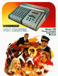
Introducing the Shure
PRO MRST€RTM
Power Console Model 706
. . . a portable, high -power, 8-input monophonic mixeramplifier combining the power and versatility
demanded by professional users with the ease of
operation of a much smaller, simpler unit. The result of
years of design concept study and evaluation, the
PRO MASTER handles any sound job dependably,
and with the very highest quality. It combines superior
performance with a relatively modest price. It is ideal
for such diverse applications as schools, churches,
hotel and motel meeting rooms, nightclubs, auditoriums-anywhere good sound is vital, regardless
of room size.
The PRO MASTER is an all solid-state unit, employing
'the latest developments in highly reliable integrated
circuit, discrete component, and printed wiring
technology It's easy to set up and operate-no separate power amps, equalizers or reverb are required.
And connecting accessory equipment is fast and
convenient.
The PRO MASTER is full of features for super
performance and super convenience-the unique
FEEDBACK FINDER'" helps maximize gain before
feedback, makes feedback location and suppression
fast and easy...exclusive PATCH BLOCK'" rear panel
shows you where you're patching, helps you construct
complex circuits using simple patch cords...efficient
"wind tunnel" power amp design has temperature
warning and shutdown LED indicators.
Its versatile control panel is human-engineered for
ease of operation: an experienced user can always
get the most from it, even in the dimmest auditorium,
meeting room, or club, and a beginning user can
operate it effectively,with minimum indoctrination and
with complete confidence. It's packaged in a handsome, rugged, lightweight, molded ARMO-DUR@
case complete with carrying handle and line
cord storage.
In combination with Shure's PRO MASTER Speaker
Svstems, vou've aot a sound reinforcement svstem
tiatat'side'al for every application. Need more bapability? The PRO MASTER is super-expandable-use
accessory mixers or power amps, stage monitor
speakers, effects devices, whatever you need can
easily be added. And it's all backed by Shure's traditional quality and reliability. It's the sound you need
; . .when you need it... and where you need it.
Just look at these featuresFull 200-watt power amplifier
Six high-impedance and six balanced lowimpedance mic inputs plus two aux inputs plus EQ
and PA (power amp) inputs
Six input channels for microphones and aux level
sources with full controls: volume, attenuation, frequency equalization, effectsheverb, and monitor
High- and low-impedance inputs may be used
simultaneouslv
Two additional aux channels with volume controls
Full master controls: monitor, volume, effects send,
reverb return, and reverb high- and low-frequency
eaualization
Outputs for all needs: monitor, effects, headphones,
aux, mic, and speakers (2)
Two common mix buses: mix output and equalizer
out~ut
Balanced mic output for "house" systems
Unique FEEDBACK FINDER with LED readout
instantly identifies feedback frequency bands
10-band graphic equalizer with minimum phase,
combining-type filters. Lowest filter is -12 dB/
octave cut-only switch; others are 213 dB adjustable
Exclusive PATCH BLOCK rear panel shows you
where to patch-jacks are located right in the block
diagram
Built-in reverb unit with provisions for external onloff
switching and external effects devices
Regulated 24 Vdc simplex supply for powering
condenser microphones
Bright red LED indicators show input clipping,
power amp peak output level, power amp overload,
power-on, temperature warning, and shutdown
m
Protected against damage from open- or shortcircuits on inputs or outputs
Protected against heat damage by ultra-reliable
cooling fan and automatic thermal shutdown circuit
Protected against radio frequency interference and
line noise
Operates on as low as 100 Vac (at reduced output)
Rugged molded ARMO-DUR case with carrying
handle and line cord storage
Listed by Underwriters' Laboratories, Inc.; listed by
Canadian Standards Association as certified
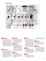
Controls Connectors lndicotors
lnpl.Jt Channels (Orange marks on contios ~ n d l c i t ehasic or nitiai settnnsi
...
..
Basically
In oddition.
MONITOR
MONITOR
Independently controls channel monitor level
to monitor output. Adjust for desired monitor
mix when using a monitor system.
Control precedes VOLUME ("pre-fader")and
other channel controls; not affected by VOLUME, EQualizers, or EFFECTSIREVERB.Only
affected by INPUT ATTEN, allowing totally
independent monitor mix.
EFFECTSIREVERB
EFFECTSIREVERB
Controls amount of reverberation and lor
external effects on channel. Adjust for des~red
amount (use low settings for vocals, higher
settings for instruments).
This channel send control follows the INPUT
ATTEN, VOLUME and EQ controls. Can be
used simultaneously with reverb and external
effects devices, or as a second monitor
("post-fader")to the EFFECTS OUTPUT jack
HI FREQ EQ
HI FREQ EQ
Sets channel treble boost or cut for desired
tone shap~ng.
Adjusts channel 213 dB at 10 kHz on all outputs except monitor; does not affect monitor
output.
LO FREQ EQ
LO FREQ EQ
Sets channel bass boost or cut for desired
tone shaping.
Adjusts channel 2 13 dB at 100 Hz on all outputs except monltor; does not affect monitor
output
INPUT CLlP
INPUT CLlP
Indicateswhen Input signal istoo high. Adjust
INPUT ATTEN until only occasional flashes are
noted.
Lights approximately 3 dB prior to clipping
of preamp or input channel equalizer. For
optimum signal-to-noise ratio, adjust INPUT
ATTEN for occasional flashes (no light may
mean noisy operation; constant light means
distortion).
INPUT ATTEN
Adjusts input attenuation for channel.
Suggested init~alsett~ngs:condenser microphones or amplified instruments -12 to -30;
normal vocals -6 to -12; loud vocals -12 to
-24; distant miking 0.
VOLUME
Allows individual setting of channel input for
desired signal mix. If setting is consistently
low (1 or 2), or high (8 to lo), adjust INPUT
ATTEN.
INPUT ATTEN
Adjusts gain of preamplifier to permit channel
to accept microphone level signals, direct
instrument pickups, or high level aux signals
from amplified instruments or tape recorders;
almost any input device can be
accommodated.
VOLUME
Affects all outputs except monitor; does not
affect monitor mix.
Inputs:
Both inputs may be used at the same time with
similar microphones (one high and one low
impedance), allowing up to 12 microphones
simultaneously.
HI IMP
HI IMP
Provides for connection of high-impedance
microphones, direct instrument pickups,
keyboards, amplified instruments, tape
recorders or other high-level sources to
channel input.
Can be used with line matching transformer
(Shure A95FP) to allow two low-impedance
microphones on channel (not recommended
for two condenser microphones).
BAL LO IMP
Also may be used to power most condenser
microphones such as the Shure SM81; built-in
c
power supply voltage
+24 ~ d simplex
activated by rear-panel switch.
Provides for connection of low-impedance
dynamic, ribbon or condenser microphones
and other low-level inputs to channel input.
(Don't use when high-level source is used on
HI IMP input.)
BAL LO IMP
I
Rux Inputs
Channels 7 and 8 are aux level inputs, providing additional input
capabilities for tape recorders, synthesizers, amplified instruments, background music sources, preamplified phonographs, or other mixers. These
channels have AUX INPUT phone jacks, VOLUME controls for settlng the
channel input mix level. To play a stereo tape in mono, connect the left tape
channel to AUX INPUT 7 and the right tape channel to AUX INPUT 8. If
equalization, reverbleffects and monitor are desired, use two of the first six
HI IMP input channels with proper input attenuation.
These inputs can also be used for the return signal from an external effects
dev~ce(delay, echo, etc.) driven by the EFFECTS OUTPUT
When an additional mixer (such as the Shure M68, M67 or SRIOI) is
connected to channel 7 or 8, the aux channel volume control becomes a
submaster control
The orange control marks indicate basic or initial settings
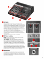
LED Stotus lndicotors
POWER-lnd~cates application of ac voltage to power supply when
rear-panel ON-OFF switch is turned on.
TEMP WARNING-Lights when unusually high temperature of 70°C
(158°F) is reached on the output transistors. Indication may be due to
blockage of air louvers, dirty air filter, or operating the console at a high
output level with a low load impedance (too many speakers or a shortclrcuited output). Indicator will turn off when transistor case temperature
drops below 70°C. If indicator lights, it is advisable to identify the cause and
make corrections to avoid shutdown.
-
SHUTDOWN-When indicator is on, power amplifier is turned off (all other
circuits remain on). The console may shut down for one of the following
excessive temperature due to inadequate cooling (see TEMP
reasons: (I)
WARNING), (2) dc voltage on speaker lines due to power transistor failure
(check forthiscondition by turning the consoleoff and turning it backon), or
(3) airflow blockage due to fan failure or air passage obstruction.
Heodphonss
A %inch phone jack is available for connection to a pair of stereo headphones. The jack is wired to the power amplifier. The signal level to the
headphones follows the MASTER VOLUME control. The headphones allow
the console to be used as a mixer for tape recording. The speakers can be
disconnected to avoid feedback.
POWER
TEMP
WARtjthiG
SHUTDOWN
HEADPHONES
I
I
Controls Connectors Indicators
-
Peak IndicatorsgEqualizer- FEEDBACK FINDERTM
DB PCAH Indicators
Are connected to power amplifier outputs and
Indicate peak output level. 0 DB PEAK equals
approxlmately 25 watts to a 4-ohm load. A 6 dB
change is a 4-tlmes power change; therefore.
-36 dB represents a 6 mW output and +6 dB a
100W output. These Indicators are also used to
provide an instantaneous readout of feedback
frequency (see FEEDBACK FINDER).(Note that
when the FEEDBACK FINDER is activated, the
DB PEAK indicators are converted to frequency
band indlcators-frequencies are shown below
the equal~zercontrols-and do not indicate the
signal level )
PA (Power Amplifier)
Overload Indicator
L~ghts
when the power ampllfler exceeds approx~mately1% dlstortlon
level (caused by clipping overload or any condition result~ng~n
Imperfect signal ampliflcatlon) The lndlcator 1s sensltlve to line voltage and speaker load condltlons The overload condtioncan generally be corrected by turnlng down the MASTER VOLUME control If
the lndlcator remains on the speaker load may be Improper or a
speaker cable may be shorted It may remaln on durlng SHUTDOWN
actlvatlon Under normal conditions th~sIndicator corresponds to a
level of +9 dB on the DB PEAK ind~catoror 200 watts to a 4-ohm load
Graphic Cqualizer
Is a 10-band fully comb~nlngm~n~mum-phase
octave type normally
connected to the power ampl~flerInput It provldes 13 dB boost or cut
at 63 125 250 500 Hz 1 2 4 8 and 16 kHz plus a BELOW63 Hz 12
dB1octave cutoff fllter The graphic equallzer permits adjustment of
the sound system frequency response for a tonal balance approprlate to the performance and a reduction In the tendency toward
feedback It can also be used to adjust an audio playback system
frequency response to compensate for variations in electrical and
acoustical response that can alter the natural sound of the recorded
materlal
3 FCCDf3ACHFINDQRTM
The graphlc equallzer can also be used to produce disco-type
sound by moderate amounts of low- and high-frequency boost
Note that equalizat~onby ear for proper sound qual~tyrequires a
certaln amount of skill and tlme. It is preferable to use acommerc~ally
available equalization analysls system such as the Shure M615AS
Equallzatlon Analyzer System, followed by feedback tunlng uslng the
bu~lt-inFEEDBACK FINDER and Indicators (see next section).
IMPORTANT Don't overequallze! Too much equalization can result In
unnatural and qu~teunpleasant sound
No Indicator 1s provlded for eltherthe 63 Hzfllter control or BELOW 63
Hzfilter swltch, any low-frequency problems lhkely to be encountered
can be eas~lyremoved by adjustment and lhstenlng tests Reduce the
the sound is
63 Hz equallzer or move the swltch to BELOW 63 ( r~f)
boomy' or ~f extremely low-frequency noises such as 'pop' or wind
nolse are causlng power ampllf~eroverload
Since the graphic equallzer controls may overemphasize or remove
desirable program materlal you should minlmlze acoustic problems
(~ncludingfeedback) by careful m~crophoneand speaker placement
before equallzlng
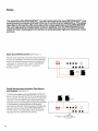
The FEEDBACK FINDER uses the LED lndlcators to provide a qulck and easy means of determlnlng
the freauencv (octave bandocation, of the most ~rominent
feedback tones The a r a ~ h i ceaualizer can
then be usedto reduce the system response at these frequencies to suppress feedback Connect all
speakers and microphones and place them In thelr proper posltlons for the performance Set master
controls and ind~vidualInput channel MONITOR. EFFECTSIREVERB and EQ controls to 0 Set all other
lndlvldual Input channel controls to the lnltlal (orange mark) posltlons Turn the FEEDBACK FINDER
swltch to ON The DB PEAK lndicators are now connected for the feedback ind~catorfunctlon Adjust
the MASTER VOLUME to just below feedback If necessary turn down the FEEDBACK FINDER
to the point where room background noise does not lhght any
THRESHOLD control from the 10 pos~t~on
DB PEAK lndlcators Increase the MASTER VOLUME unt~lfeedback just occurs and note the h~ghest
frequency band with a lit LED Reduce the equalizer settlng in thls band untll feedback stops Repeat
the last two steps until the feedback sound becomes a combination of a number of tones or until one
equal~zercontrol has been set to -10 IMPORTANT Don t overadjust the equal~zerlToo much equalizatlon can result In unnatural sound Wlth practlce the FEEDBACK FINDER can be used to equalrze for
feedback w~thoutsubjecting the aud~enceto ear-spl~ttingfeedback levels
When completed perform a lhstenlng test uslng program materlal s~mllarto the planned performance
and if necessary make sl~ghtadjustments to the equal~zersto prov~dethe most pleasing sound
IMPORTANT This console has a power-l~mitingfeature whlch permits FEEDBACK FINDER operatlon
wlthout allowlng feedback to reach ear-spl~ttinglevels A clrcult at the power ampllfler Input limlts the
amplifier to approxlmately 13% (26 watts) of full rated output To Insure full power operatlon the
after setup
FEEDBACK FINDER swltch MUST be returned to the OFF pos~t~on
When using the graphic equallzer for stage monltor speakers, feedback suppression of the monltor
system is performed after the house system and wlth the maln speakers off The monitor speakers must
be In thelr f~naloperating positions relatlve to the mlcrophones used Use the same procedure as for the
house system except use the lndlvldual MONITOR level and MASTER MONITOR controls for level
adjustments If more than one performer's microphone 1s involved select the lead performer or center
thls procedure a
stage mlcrophone foroperat~onIn thefeedbacksuppress~onprocedure NOTE Dur~ng
person must stand In front of or hold (slmulatlng a performer) the mlcrophone belng equalized Slnce
excessive low-frequency signals are not usually deslrable for stage mon~tors,~tmay be advisable to set
the equal~zerFLATIBELOW 63 switch of the monltor channel to BELOW 63, the 63 Hz control to -10, and
the 125 Hz control to -5 Adjust the FEEDBACK FINDER THRESHOLD MASTER MONITOR and
EQuallzer controls uslng the procedure previously descr~bedConduct a volce test and check for
Make a s~m~lar
check of all other mlcrophones belng fed to the mon~tor
adequate level and ~ntelllglb~lity
system lntell~g~b~lity
may be improved if deslred by a sl~ghtincreaseof equal~zercontrolsin the 1 kHz to
4 kHz range provldlng the deslred level can be maintamed w~thoutfeedback If feedback or ringing
1s encountered at any mlcrophone location try adjusting the positlon of and/or the dlstance to the
nearest speaker
m ~ a s t c Controls
r
Basically..
.
In addition
...
Master Monitor
Controls monltor mlx level to MONITOR
OUTPUT lack.
Master Monitor
Control precedes VOLUME and other channel
controls. Only affected by INPUT ATTEN and
channel MONITOR controls.
Reverb Return
Controls reverb level to channel signal mix.
Reverb Return
Th~scontrol follows the INPUT ATTEN, input
VOLUME and EQ, and EFFECTSIREVERB
channel controls, as well as the REVERB EQ
controls. Not affected by the MONITOR
controls, or follow~ngmaster controls.
Reverb HI EQ
Sets reverb signal treble boost or cut for
desired tone shaping.
Reverb HI EQ
Adjusts master reverb signal high-frequency
equalization on output. Does not affect
MONITOR OUTPUT or EFFECTS OUTPUT
Reverb LO EQ
Sets reverb signal bass boost or cut for
desired tone shaping.
Reverb LO EQ
Adjusts master reverb signal low-frequency
equalization on output. Does not affect
MONITOR OUTPUT or EFFECTS OUTPUT.
Effects Send
Controls level of effects amplifier signal to
EFFECTS OUTPUT jack.
Effects Send
Affected by channel INPUT ATTEN, EQ,
VOLUME and EFFECTSIREVERBchannel
controls Used for external effects or second
monitor.
Master Volume
Adjusts level of channel mix. Controls level of
channel signals from mic inputs 1-6 and aux
inputs 7 and 8 to all outputs except MONITOR
and EFFECTS.
Master Volume
Does not affect s~gnalsadded to COMmon
MIX jacks or EQ and PA INPUTS.
controls connectors Indicators (continued)
Power and Speaker Connections
Power ON-OFF Switch
Applies ac power to power supply (does not switch ac outlet).
.~nswitched
AC Grounded Outlet
Provides up to 100 watts of ac power to accessory equipment
(mixer, tape recorder, lamp, etc.).The outlet is not fused and not
switched; use the power switch on the accessory equipment.
The outlet is not intended for use with high-power equipment
such as power amplifiers.
@AC line Cord
Connect to ac power (120 Vac ? lo%, 50160 Hz). Use only 18
AWG (or larger), three-wire extension cords. Console may draw
up to 4 amperes (500 watts) from ac supply circuit. May be
operated from other voltages (see Service Manual).
.4A,
250V Fuse
Protects console power supply aqa~nstoverload. (Replace only
i type ' 4 k ,SLO-BLO, 250Y type 3AG.)
with ident~cas ~ zand
OSpeoker Outputs Jock (2)
Connect to speaker systems such as the Shure 701 or 709.
Suggested speaker loads for the console include:
2-Shure Model 701 or 709 PRO MASTERTM
Speaker
Systems (8 ohms each), or
4-Shure Model 702 Stage Monitor Speaker Systems (16
ohms each), or
2-Shure Model 703 PRO MASTER'" Stage Monitors (8
ohms each), or
4-Shure Model SR103 Speaker Columns (16
ohms each), or
2-Shure Model SR112 or SR116 Compact Speaker
Systems (8 ohms each).
Connecting too many speakers to either or both output jacks may
result in a combined load below the 4-ohm minimum. Operation
with such a load may cause an excessively high internal temperature (TEMP WARNING LED turns on), or the PA (power
amplifier) OVERLOAD LED may turn on at lower than normal
levels (before the +6 dB LED). Note that no damage will result;
the console is protected against speaker overloads and shorts.
Also, the console may be operated without speakers (with headphones) for tape recording.
PRTCH OLOCH'" Rear Panel
e ~ i m p l e x24V Switch
Turn on when powering low-impedance condenser microphones from the console; turn off when not used. Balanced
low-impedance microphones may be used in combination
with condenser microphones. NOTE: Do not turn on when
using unbalanced low-impedance microphones. The built-ln
24 Vdc simplex voltage IS applied to input channels 1 through
6 BAL LO IMP connectors to power most condenser microphones. Make sure the microphone(s)will operate properly
with 24 Vdc open-circuit voltage and a 1.8k powering resistor.
Monitor Output Jack
Prov~desunbalanced line level output (intended for connection to unbalanced auxiliary or line bridging inputs) for separate monitor amplifier system. Output (pre-fader) precedes
channel VOLUME, EQualization, and EFFECTSIREVERB
controls. Adjust ~nd~vidual
channel MONITOR controls for
desired mix, and MASTER MONITOR control for overall level.
Connect to PA (power amplifier) INPUTor EQual~zerINPUT to
use console power amp or graphic equalizer for monitor, or
connect to external power amplifier.
.Reverb
Switch Jack
@€Q lnput Jack
Provides for connection of remote reverb footswitch; reverb
channel and master controls can be preset and added by
performers when needed. Switch closure acts the same as
turnlng down the REVERB RETURN control, disabling the
reverb. Footswitch cable need not be sh~elded.
Provides for insertion of sianais from MONITOR or EFFECTS
OUTPUT from the console"or from an external mixer, at the
same time disconnecting the normal signal. The inserted
signal w~llbe affected by the graphic equalizer, but not by the
MASTER VOLUME control. If there is no connection at the PA
INPUT, the inserted signal passes to the power amplifier, and
the graphic equalizer and power ampl~fierare used for the
monitor or effects system. lnserted signal is not affected by
any PRO MASTER volume controls, so console should be
turned off when connecting external equipment to this jack.
@€ffects Output Jack
Connect to external effects devices such as echo, delay,
flanger, or phase shifter input. Affected by channel INPUT
ATTEN, VOLUME, EQ and EFFECTSIREVERBcontrols, and
master EFFECTS SEND control. Connect effects device output (return) jack to AUX INPUT 7 or 8. Aux channel VOLUME
control becomes effects return control. EFFECTS OUTPUT
jack may be used as second (post-fader) monitor by connecting to external power amp or console PA (power amplifier) or
EQ INPUT
TEQ
Output Jack
This COMmon MIX (output-input) jack provides for pick~ng
off
the equalized signal for connection to a tape recorder or
another power amplifier, or insertion 6f signals from other PRO
MASTER consoles in addition to the existing equalized signal.
lnserted signal is not affected by any console controls.
@Mix Output Jack
This COMmon MIX (output-input) jack provides a postMASTER volume, pre-graphic equalizer output or input for
picking off the mix for Insertion into tape recorders or other
power amplifiers, or inserting external s~gnalsfrom other PRO
MASTER'" consoles.
P
.A
lnput Jack
Provides for insertion of signals into power amplifier from
console outputs (MONITOR,EFFECTS, etc.),at the same time
disconnecting the normal s~gnal.lnserted signal is not
affected by any PRO MASTER console controls, so console
should be turned off when connecting external equipment to
this jack.
@RUX Output Jack
Provides aux level signal to tape recorder, other mlxer or
amplifier, or house sound system. Signal is pre-graphic
equalizer and is affected by all other console controls except
monitor.
~- M IOutput
C
Jack
Provides balanced, low-impedance, microphone-level s~gnal
to tape recorder or house sound system when used In conjunction with built-in systems. Allows PRO MASTER console
to be used for mixing, monitoring or recording. Connect to
low-~mpedancemicrophone input jack. Signal is pre-graphic
equalizer and is affected by all other controls except monitor.
Setups
The versatility of the PRO MASTERTM
is in part achieved by the many PATCH BLOCKTM
(rear
panel) inputs and outputs which permit its use in a wide variety of applications. The setups
described in this section offer some idea of the varied applications of the PRO MASTER.
Use only high-quality, shielded patch cords for patching. Turn the PRO MASTER power
switch off when making patch connections to avoid possible high-level transients, noise
and hum.
Basic Sound Reinforcement (See Setup 1.)
No rear panel patching is required. Plug in the microphones and speakers. Set the front panel operating
controls as desired (orange marks on controls indicate basic or initial settings). Use the FEEDBACK
FINDERTM
and graphic equalizer to suppress
feedback tones.
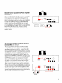
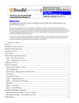
Sound Reinforcement and Mono Tape Record
and Playback (See Setup 2.)
Connect the s~eakersto the SPEAKER OUTPUTS
jacks. connect the AUX OUTPUT to the tape recorder
aux input jack, and the tape recorder aux output to a
channel 7 or 8 AUX INPUT jack. Note that the tape
recorder input is not affected by the graphic equalizer.
If the frequency-shaping effects of the graphic
equalizer are desired during recording, connect the
tape recorder aux input to the PRO MASTER EQ
OUTPUT jack. In the playback mode, the graphic
equalizer can be used as a tone control.
AUX
@ a 0 ?0
@ aa @
a*
SPEAKER
ouTPUTs
AUX
IN
TO CHANNEL 7 OR 8
INPUT
4 DI A E $ ~ ~ ~ ~
AuX
OUTPUT
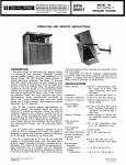
Stage Monitor and "House" Sound System
(See Setup 3.)
When a "house" system is to be used as the prime
sound system, the PRO MASTER can be used as the
system mixer, and also provide a monitor output as
follows. Patch the MONITOR OUTPUT jack to the EQ
INPUT jack. Connect the MIC OUTPUT to the house
system low-impedance mic input. Connect the
SPEAKER OUTPUTS to the monitor speakers. Adjust
the MONITOR controls for the desired monitor
speaker level, and the graphic equalizer controls for
optimum monitor sound and minimum feedback.
Adjust the channel VOLUME and MASTER VOLUME
controls for the desired house system level. Note that
the monitor is pre-fader and adjustments to the
monitor and house systems are independent. If postfader is desired, connect the EFFECTS OUTPUT to
the EQ INPUT and adjust the EFFECTSIREVERBand
EFFECTS SEND controls for the desired monitor level.
Now both the house and monitor systems are controlled by the channel VOLUME controls. Note too that
the house system is not affected by the graphic
equalizer.
OUTPUT
SPEAKER
OUTPUTS
MONITOR
OUTPUT
TO HOUSE SOUND
SYSTEM MIC INPUT
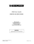
Sound Reinforcement and External Effects
Device (See Setup 4.)
Connect the EFFECTS OUTPUT jack to the input of
the external effects device (echo, flanger, etc.), and
the effects device output to a channel 7 or 8 AUX
INPUT jack. The effects-modified signal appears at all
PRO MASTER output jacks except the MONITOR
OUTPUT
SPEAKER
OUTPUTS
I INPUT
TO CHANNEL 7 OR 8
AUX INPUT
OUTPUT
Separate Monitor Equalizer and Power Amplifier
(See Setup 5.)
When the SPEAKER OUTPUTS are being used for the
main speakers and a separate monitor system is
desired, connect the MONITOR OUTPUT jack to the
input of a separate equalizer (such as a Shure SR107).
Connect the equalizer output to a separate power
amplifier (such as a Shure SR105B) and connect
monitor speakers. The monitor system is only affected
by the PRO MASTER INPUT ATTEN, MONITOR, and
MASTER MONITOR controls. This setup allows
independent adjustment of the main and monitor
speaker levels.
MONITOR
OUTPUT
SPEA
OUTF,
,
I
~%I\K~Rs
EQUALIZER
POWER
AMPLIFIER
Two Consoles with Main and Monitor Speakers
(Common Mix) (See Setup 6.)
This setup combines all inputs on both consoles
and provides separate main and monitor graphic
equalizers and power amplifiers. Connect the MIX
OUTPUT jacks of the two consoles together. Connect
the MONITOR OUTPUTof console A to the EQ INPUT
of console B. Connect the MONITOR OUTPUT of
console B to the console B EQ OUTPUT jack. Connect the main speakers to console A SPEAKER OUTPUTS and monitor speakers to console B SPEAKER
OUTPUTS. Console A can accept vocal inputs for
both main and monitor speakers. Console A's graphic
equalizer is used to enhance sound and minimize
feedback for all inputs to the main speakers. Console
B will accept instrument inputs (guitars, keyboards,
etc.) for both main and monitor speakers. Console B's
graphic equalizer minimizesfeedback and enhances
only the vocal inputs to the monitor speakers. Note
that the instrument inputs to the monitor speakers
bypass the graphic equalizer and are unaffected by
the necessary vocal monitor equalization.
MAIN
SPEAKERS
ID..
OUTPUTS
A
SPEAKER
-, ,Tn, , T O
MONITOR
SPEAKERS
..-. .. - .
OUTPUT
.
r'
Operotion
1 . Position the microphones and connect them to the
PRO MASTER'" Use both inputs on each channel ~f
more than SIX microphones are to be connected.
Use low-impedance microphones and cables to
minimize loss and interference if long microphone
cable lengths are needed.
2. Position the speakers and connect them to the PRO
MASTER. Make sure the combined speaker load is
not less than 4 ohms. Use minimum cable lengths to
maximize output power. Use the proper cable size
for the required length.
3. Make any rear-panel patching connections
required (refer to SETUPS section). All patching
connections except the MIC OUTPUTare standard
two-conductor, %-inch phone jacks.
4. Connect any external effects device to the PRO
MASTER EFFECTS OUTPUT and AUX INPUT
jacks. Power for the external effects device can be
obtained from the PRO MASTER rear-panel
UNSWITCHED AC receptacle (100 watts
maximum).
5. Connect the PRO MASTER line cord to an ac source
capable of supplying 500 watts. If extension cords
are required, make sure they are 18 AWG or larger.
6. Make sure the PRO MASTER air louvers are not
blocked. Check to make sure the air filter is clean
7. In low ambient light conditions, a high-intensity,
low-wattage lamp (not supplied) can be plugged
into the rear-panel UNSWITCHED AC receptacle
(1 00 watts maximum).
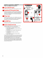
8. If des~red,the supplied Instruction Plate can be
mounted on the PRO MASTER front panel above
the DB PEAK indicators. IMPORTANT The Instruction Plate adhes~vebacking is designed for permanent mounting; for temporary mounting, leave the
paper backing in place and use double-sided tape.
D . TEMP WARNING-Check for air blockage,
dirty air filter, shorted speaker cable or excessive
heat near the console.
E. SHUTDOWN-Check for excessive console
heating or cooling fan failure.
Mointenonce
The PRO MASTER is an exceptionally
well-designed unit. All components are of the
highest quality, operating well within their
respective ratings to assure long life. The following list of Do's and Don'ts describes minimal operating precautions and maintenance to
provide years of dependable service.
DO clean the air filter every 100 hours of
operation (more frequently in dusty or dirty
areas). Stand the console on its rear bumpers, remove the screw securing the filter, and
slide it out of its slot. Rinse the filter in water or
a mild detergent solution, allow to dry, and
replace.
DO unplug the console before cleaning. DO
clean the outer surfaces of the console with a
clean, damp cloth and mild detergent. DON'T
use strong solvents or cleaning fluids.
DO use an 18 AWG or larger heavy-duty
extension cord when additional line cord
length is needed.
DON'T operate the console with air louvers
blocked, or placed on a radiator or heatproducing equipment. Avoid operation in
direct, hot sunlight.
9. Set the front-panel controls to their initial settings
(orange marks). Set the INPUT ATTEN controls for
the usage on each input. Turn on the rear-panel
power ON-OFF switch.
DON'T replace the rear-panel fuse with a
different size or type. Use only 4A, SLO-BLO,
250V, type 3AG.
10. Adjust the MASTER VOLUME control to the desired
level. Using program material similar to the actual
performance, adjust the MONITOR, EFFECTS1
REVERB and EQ controls as desired for the most
pleasing sound.
DON'T risk fire or shock hazard by operating
the console in rain.
11. Using the FEEDBACK FINDER" set the equalizer
for the highest feedback-free sound level. The
equalizer controls can then be "touched up" for
most pleasing sound.
12. During operation, observe the various LED
indicators for possible setting corrections:
A. INPUT CLIP-If on constantly, use the INPUT
ATTEN to reduce the input signal and eliminate
the distortion. (Set for occasional flashing.)
B. D B PEAK-Observe
power level.
14
action to monitor output
C. PA OVERLOAD-If on constantly, reduce
volume andlor check speaker load.
DON'T use unbalanced low-impedance
microphones with the SIMPLEX 24V switch
on; turn off the switch if not required for powering condenser microphones. If simplex
power is in use, connect unbalanced lowimpedance microphones through a line
matching transformer (Shure A95UF)
to a HI IMP INPUT:
Troubleshooting
Should any difficulty be encountered in
console operation, the problem can often be
traced to some simple source such as an error
in interconnection. The.following is offered as a
basic guide to this type of problem.
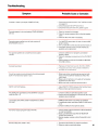
Troubleshooting
Symptom
Probable Cause or Correction
Console IS "dead" (no output, POWER LED off)
1. Check that ac power source is "live" and that console
is plugged in.
2. Check that power ON-OFF switch is on.
3. Check that rear-panel fuse (4A, 250V) is good.
Console appears to be overheating (TEMP WARNING
LED on)
1. Check air louvers for blockage.
2. Check for proper speaker load or shorted speaker
cable.
3. Check air filter and clean if necessary
Console power ampl~fierturns off and remains off
(SHUTDOWN LED on)
1 Turn MASTER control down for one mlnute to allow
proper cool~ng
2. Turn console off for a few seconds and turn back on.
3. If shutdown persists, have console checked by
qualified service personnel.
No signal at speaker (all console functions appear
normal)
1. Check for defective or improperly connected
speaker cables.
2. Check for improper connections to EQ or PA INPUT
jacks.
3. Check settings of channel VOLUME and MASTER
VOLUME controls.
Console fuse blown
1 Replace w~th~dent~cal
fuse (4A, SLO-BLO, 250V)
2 If second fuse blows, have console checked by
quailfled service personnel
One of two inputs on same channel not working properly
(both %-inchand 3-pin jacks in use)
1. Make sure similar microphones are used on both
inputs, and microphone impedances match the
inputs used.
2. Make sure microphone is not used with accessory
equipment on other input.
3. Make sure both microphone switches are on
INPUT CLIP LED flashing
1. Adjust INPUT ATTEN to reduce channel input level.
2. Reduce input signal level at source.
PA OVERLOAD LED flashes while DB PEAK indicators
read less than +6
1. Check for defective (shorted) speaker cable.
2. Check that load impedance is not too low (too many
speakers are connected).
Loud noise clicks when certain microphones or cables
are used
1. SIMPLEX 24V switch is on (when not needed).
2. Unbalanced cable used when SIMPLEX 24V switch
is on.
3. Check for defective microphone cables.
No monitor output (program output normal)
1. Check monitor output connection to EQ or PA INPUT,
or external amplifier.
2. Make sure MONITOR and MASTER MONITOR
controls are turned up.
3. Monitor speaker volume control (if present) turned
down.
Sound quality poor (weak or thin)
1. Excessive equalization on graphic equalizers
2. Defective input or patching cables.
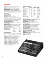
Type: Solid-state power console using discrete
components and integrated circuits
Inputs: Eight input channels: six high- and/or balanced
low-impedance mic inputs, plus two aux inputs
Graphic Equalizer: 10-band, fully combining,
minimum-phase, octave type, normally connected to
power amplifier input; 13 dB boost or cut at 63,125,250,
500 Hz, I , 2 , 4 , 8 and 16 kHz; BELOW 63 Hz 12 d B /
octave cutoff filter (10 dB down at 31 Hz)
Power Output:
200W min. to 4 ohms
125W min. to 8 ohms
Measured at 1 kHz, 120 Vac, 1% THD
Distortion: THD typically less than 0.1% at 40 Hz and
1 kHz, 0.25% at 15 kHz, IM distortion typically less than
0.25% (Output: 180W or less to 4 ohms, 1lOW or less to
8 ohms, measured from low-impedance input with individual and master controls at typical settings)
Low- and High-Frequency
lnput Equalization: t 1 3 dB at 100 Hz and 10 kHz
lnput Clipping Indicators: Light 3 dB below input or
equalizer clipping level
DB Peak Indicators: Indicate power amplifier peak
voltage; +6 dB LED indicates 100 watts sine-wave
output to 4-ohm load
PA Overload Indicator: Lights when power amplifier
THD exceeds 1%; fully on at 5%
Input Sensitivity:
BAL LO IMP
0.6 mV
(full power output)
HI IMP
8 mV
AUX
108 mV
EQ INPUT
960 mV
PA INPUT
960 mV
lnput Clipping Level:
BAL LO IMP 700 mV to 21 mV (INPUT ATTEN -30 to 0)
HI IMP
1OV to 335 mV (INPUT ATTEN -30 to 0)
AUX
30V to 10V (VOLUME from 0 to 10)
Voltage Gain:
94 dB BAL LO IMP INPUT to SPEAKER OUTPUTS
71 dB HI IMP INPUT to SPEAKER OUTPUTS
49 dB AUX INPUT to SPEAKER OUTPUTS
64 dB BAL LO IMP INPUT to MIX OUTPUT
77 dB BAL LO IMP INPUT to MONITOR OUTPUT
74 dB BAL LO IMP INPUT to EFFECTS OUTPUT
22 dB BAL LO IMP INPUT to MIC OUTPUT
58 dB BAL LO IMP INPUT to AUX OUTPUT
81 dB BAL LO INPUT to HEADPHONE OUTPUT
0 dB EQ INPUT to EQ OUTPUT
30 dB PA INPUT to SPEAKER OUTPUTS
Levels and Impedances:
Circuit
Nominal Maximum Actual
Working
Level
Level
Impedance Impedance
BAL LO IMP INPUT 5 mV
HI IMP INPUT
50 mV
0.5V
AUX INPUT
1V
MIX OUTPUT
EFFECTS OUTPUT 1V
MONITOR OUTPUT 1V
EQ INPUT
1V
1V
EQ OUTPUT
AUX OUTPUT
1V
5 mV
MIC OUTPUT
PA INPUT
1V
SPEAKER OUTPUT
-
700 mV
10V
30V
9V
9V
9V
10V
9V
9V
75 mV
10V
28.3V
HEADPHONES
-
10V
1k
145k
50k
2.4k
2.4k
2.4k
50k
2.4k
2.4k
70ohms
50k
19-300 ohms
1OOkor less
1Ok or less
2k or more
2k or more
2k or more
1Ok or less
2k or more
2k or more
19-300ohms
1Ok or less
4 ohms or
more
360 ohms 4 ohms or
more
Frequency Response: 2 2 dB, 40 to 20,000 Hz, BAL
LO IMP INPUT to SPEAKER OUTPUTS
Hum and Noise: (20 Hz to 20 kHz) - 127 dBV
equivalent input noise (BAL LO IMP)
Noise: (300 Hz to 20 kHz) - 128 dBV equivalent input
noise (BAL LO IMP)
Signal-to-Noise Ratio: Greater than 80 dB (below full
output) at typical control settings (orange marks,
MASTER VOLUME at 5, INPUT ATTEN at - 12)
Mic lnput Simplex Power: 24 Vdc open-circuit,
1.8k series resistance
Power Requirements: 120 Vac k l o % , 50160 Hz;
500W max. (For other voltages, see Service Manual)
Environmental Conditions
Operating: - 7" to 43°C (20" to 110°F)
Storage: -40" to 74°C (-40" to 165°F)
Overall Dimensions: 190 mm H x 584 mm W x 508 mm
D (7% in. x 23 in. x 20 in.)
Weight: 18.2 kg (40 Ibs)
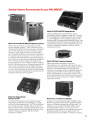
Speaker Systems Recommended for your PRO MRST€RTM
n
Model 701 and 709 PRO MASTER Speaker Systems
W~de-rangehlgh eff~ciency,l~ghtwe~ght
portable
two-wav weaker svstems-ldeal c o m ~ a n l o n sto the
700 Se;ies PRO MASTER Power consoles. The Model
701 provides high SPL sound re~nforcementof wide
frequency range program material in every location
from the largest auditoriums to the most intimate clubs.
The speaker system consists of a 15-inch woofer in a
front-ported bass reflex cabinet, and a high-frequency
horn and driver combination with adiustment for either a
~ o n Eas~ly
60" or 120" hor~zontalhorn d ~ s ~ e r s angle
b~ampedMaximum recommended ampl~fieroutput to
150 watts cOntlnuOus Frequency
50
Hz to 15 kHz lmpedance 8 ohms Model 709 has a
15-Inch woofer ln a ported
three ~
~
t r ~ chorns Su~tablefor use w ~ t hampl~f~ers
w ~ t hthe same
maximum Output and Impedance as used with the 701
Frequency response 50 Hz to 20 kHz
Model 702 Stage Monitor
Speaker System
A compact, high-quality, two-way speaker system
designed for localized sound coverage in on-stage
monitor (foldback) applications. The 702 may be used
with virtually any power amplifier delivering up to 50
watts to a 16-ohm load. It can be placed in either of two
slanted positions facing the performer. Built-in volume
control. Frequency response: 100 Hz to 20 kHz.
Impedance: 16 ohms.
Model 703 PRO MASTER Stage Monitor
Th~sIS a profess~onaltwo-way mon~torsystem
des~gnedfor years of rugged on-stage use It has two
8-~nchspeakers and a h~gh-frequencydr~vercoupled
angle may be
to a 120" radial horn Horn d~spers~on
reduced to 60" for t~ghtercontrol of foldback s~gnalCan
at 30" or 60" angle to the stage Maximum
be pos~t~oned
recommended ampl~f~er
output 100 watts cont~nuous
to 8 ohms Frequency response 100 Hz to 16 kHz
Impedance 8 ohms
Model 708 High-Frequency Speaker
W~tha h~gh-powercompresslon drlver and
high-frequency horn, the Model 708 meets the most
demand~ngrequ~rementsfor custom speaker stacks In
addltlon
~
can ~
addlflonal
~
high-frequency
~
l
~
emphas~sIn full-range systems Adjustable d~spers~on
knob permits 60" or 120" horlzonta~
coverage
B u ~ l t - ~h~qh-frequency
n
crossover filter Max~mumrecommended amplifier output. 150 watts continuous to an
8-ohm load. Frequency response: 2,000 to 15,000 Hz.
Impedance: 8 ohms.
Model 707 Low-Frequency Speaker
Designed for custom speaker stack installations, the
Model 707 operates with amplifiers capable of deliverIng up to 150 watts continuous to an 8-ohm load. The
speaker can be used with the Model 708 to make a
full-range speaker system, or in conjunction with
another full-range system for low-frequency emphasis.
Beveled back permits use as a stage monitor. Frequency response: 50 to 2,600 Hz. Impedance: 8 ohms.
~
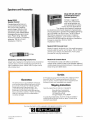
Speakers and Accessories
Model SR103
Speaker Column
Outstanding performance in
sound reinforcement systems.
This column has a wide frequency range, distortion-free
reproduction and high sound
penetration power. Model SR103
is designed for permanent installation. Power rating: 100 watts
maximum to 16 ohms. Frequency
response: 100 Hz to 15 kHz.
Impedance: 16 ohms.
monitor and club applications.
They feature wide frequency response,
low distortion and smooth dispersion characteristics,
and are designed to operate with amplifiers delivering
up to 100 watts to an 8-ohm load. The SR112B and
SR112W are designed for permanent installation
(SR112W is woodgrain, scuff resistant vinyl finish),
and the SR116B is portable for temporary installations.
Frequency response: 45 Hz to 16 kHz.
Impedance: 8 ohms.
Model A700C Console Cover
Made of rugged, reinforced vinyl, this useful accessory
protects against weather and scrapes. Slip-on design
permits quick setups and takedowns. Front cutout
provides for carrying handle use.
A95 Series Line Matching Transformers
Adapt high-impedance microphone to low-impedance
console inputs, and low-impedance microphone to
high-impedance inputs. Model A95UF plugs directly
into console input.
Model A7S Console Stand
This handsome, sturdy unit makes a convenient
support when a table or desk is not available. Made of
durable steel tubing and particleboard, it is quickly and
easily set up and taken down.
Service
Guarantee
This Shure product is guaranteed in normal use
to be free from electrical and mechanical defects
for a period of one year from date of purchase.
Please retain proof of purchase date. Th~s
guarantee includes all parts and labor. This
guarantee is in lieu of any and all other guarantees or warranties, express or implied, and there
shall be no recovery for any consequential or
inc~dentaldamages.
If information or service should be required, contact your local
Shure PRO MASTER'" dealer explaining your difficulty in
detail. In addition, the Shure factory service department will
be ready to assist you Immediately upon request.
Shipping Instructions
Carefully repack the unit and return it prepaid to.
Shure Brothers Incorporated
Attention: Service Department
1501 West Shure Drive
Arlington Heights, Illinois 60004
If outside the United States, return the unit to your dealer or
Authorized Shure Service Center for repair. The unit will be
returned to you prepaid.
For more information on Shure speakers and speaker accessories, write:
=$A SHURE
Shure Brothers Inc., 222 HarIrey nve., tvansron,
Copyr~ght1980, Shure Brothers Inc
27A8003 (TK)
IL auLur
6.S.A.
Prtnted In U S A