1
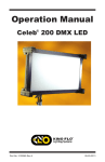
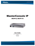
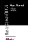
CS-PENT
CompuSwitch PENT
®
User Guide
Release 1.0
Copyright © 2006 Raritan Computer, Inc.
CSP-0A-E
August 2006
P/N
This page intentionally left blank.
Copyright and Trademark Information
This document contains proprietary information that is protected by copyright. All rights reserved.
No part of this document may be photocopied, reproduced, or translated into another language
without express prior written consent of Raritan Computer, Inc.
© Copyright 2006 Raritan, CompuSwitch, Paragon, MasterConsole, and the Raritan company
logo are trademarks or registered trademarks of Raritan Computer, Inc. All rights reserved. Java
is a registered trademark of Sun Microsystems, Inc. Internet Explorer is a registered trademark of
Microsoft Corporation. Netscape and Netscape Navigator are registered trademarks of Netscape
Communication Corporation. PS/2, PC/AT, RS/6000, and PC/AT are registered trademarks of
International Business Machines Corporation. All other marks are the property of their respective
owners.
FCC Information
This equipment has been tested and found to comply with the limits for a Class A digital device,
pursuant to Part 15 of the FCC Rules. These limits are designed to provide reasonable protection
against harmful interference in a commercial installation. This equipment generates, uses, and can
radiate radio frequency energy and if not installed and used in accordance with the instructions,
may cause harmful interference to radio communications. Operation of this equipment in a
residential environment may cause harmful interference.
Japanese Approvals
Raritan is not responsible for damage to this product resulting from accident, disaster, misuse,
abuse, non-Raritan modification of the product, or other events outside of Raritan’s reasonable
control or not arising under normal operating conditions.
C
UL
US
LISTED
1F61
I.T.E.
For assistance in the North or South America, please contact the Raritan Technical Support Team
by telephone (732) 764-8886, by fax (732) 764-8887, or by e-mail [email protected]
Ask for Technical Support – Monday through Friday, 8:00 a.m. to 8:00 p.m., Eastern.
For assistance around the world, please see the back cover of this guide for
regional Raritan contact information.
Safety Guidelines
To avoid potentially fatal shock hazard and possible damage to Raritan equipment:
• Do not use a 2-wire power cord in any product configuration.
• Test AC outlets at your computer and monitor for proper polarity and grounding.
• Use only with grounded outlets at both the computer and monitor. When using a backup UPS,
power the computer, monitor and appliance off the supply.
Rack Mount Safety Guidelines
In Raritan products which require Rack Mounting, please follow these precautions:
• Operation temperature in a closed rack environment may be greater than room temperature.
Do not exceed the rated maximum ambient temperature of the appliances (see Appendix A:
Specifications).
• Ensure sufficient airflow through the rack environment.
• Mount equipment in the rack carefully to avoid uneven mechanical loading.
• Connect equipment to the supply circuit carefully to avoid overloading circuits.
• Ground all equipment properly, especially supply connections, such as power strips (other
than direct connections), to the branch circuit.
CONTENTS
i
Contents
Chapter 1: Introduction .................................................................. 1
Product Overview........................................................................................................ 1
Product Photos............................................................................................................ 1
Product Features......................................................................................................... 2
Package Contents....................................................................................................... 2
Chapter 2: Installation.................................................................... 3
Initial Configuration ..................................................................................................... 3
Installation Notes......................................................................................................... 4
Chapter 3: Operation ...................................................................... 5
Overview ..................................................................................................................... 5
Front Panels................................................................................................................ 5
Front Panel Operation................................................................................................. 6
Select a Channel ...............................................................................................................................6
Scan Channels ..................................................................................................................................6
Set Scan Rate ...................................................................................................................................6
Skip....................................................................................................................................................6
Appendix A: Specifications ............................................................ 7
Desktop Models .......................................................................................................... 7
Power .......................................................................................................................... 7
Cables ......................................................................................................................... 8
Accessories................................................................................................................. 8
Important Information for CompuSwitch Installation.................................................... 8
Appendix B: Troubleshooting ......................................................... 9
Appendix C: Cable Support Bracket Kits ..................................... 11
RCS24 to CS-PENT 2/CS-PENT 4 ........................................................................... 11
RCS8 to CS-PENT 8 ................................................................................................. 12
ii
FIGURES
Figures
Figure 1 CS-PENT 2 Unit............................................................................................................................. 1
Figure 2 CS-PENT 4 Unit............................................................................................................................. 1
Figure 3 CS-PENT 8 Unit............................................................................................................................. 1
Figure 4 Rear Panel of CS-PENT 2 Unit ...................................................................................................... 3
Figure 5 Rear Panel of CS-PENT 4 Unit ...................................................................................................... 3
Figure 6 Rear Panel of CS-PENT 8 Unit ...................................................................................................... 3
Figure 7 Cabling Details............................................................................................................................... 4
Figure 8 Front panel of CS-PENT 2 Unit...................................................................................................... 5
Figure 9 Front Panel of CS-PENT 4 Unit ..................................................................................................... 5
Figure 10 Exploded View of Scan Rates from the CS-PENT 4 Front Panel ................................................ 5
Figure 11 Front Panel of CS-PENT 8 Unit ................................................................................................... 5
Figure 12. RCS24 to CS-PENT 2/CS-PENT 4 Installation ......................................................................... 11
Figure 13. RCS8 to CS-PENT 8 Installation............................................................................................... 12
CHAPTER 1: INTRODUCTION
1
Chapter 1: Introduction
Product Overview
Congratulations on your purchase of Raritan’s CompuSwitch-PENT, which enables efficient
control of multiple computers, any combination of PC/ATs, and PS/2s, from only one keyboard,
monitor, and mouse. The 8-channel model connects and controls up to 8 computers, the 4-channel
model connects and controls up to 4 computers, and the 2-channel model connects and controls 2
computers.
CompuSwitch-PENT is built with Raritan’s unique intelligent emulation technology, which
dedicates and individual processor to each connected computer so that each computer always sees
its own keyboard and mouse. This prevents keyboard and mouse lockups and ensures flawless
bootup and operation of any mix of computers running any operating system.
Product Photos
Figure 1 CS-PENT 2 Unit
Figure 2 CS-PENT 4 Unit
Figure 3 CS-PENT 8 Unit
2
CS-PENT USER GUIDE
Product Features
•
•
•
•
•
•
Dedicated keyboard and mouse emulators to ensure automatic booting and proper operation
of each computer
VGA, SVGA, and XGA high resolution video support
Simple operation either from the CompuSwitch-PENT front panel
SCAN function to automatically cycle through all channels at a selectable scan rate from 1 to
16 seconds by using push buttons on the front panel
SKIP function to automatically bypass channels without a powered computer connected
Easy-to-manage, tangle-proof, high-resolution PC cables
Package Contents
(1) CompuSwitch-PENT unit
CHAPTER 2: INSTALLATION
3
Chapter 2: Installation
Initial Configuration
Begin by connecting one computer, and once proper operation is confirmed, proceed to
connecting any additional computers.
Important: Make certain all computers are powered OFF before starting
installation.
1. Plug the monitor, keyboard, and PS/2 mouse into the ports marked VGA MONITOR, PS/2
or AT KEYBOARD, and PS/2 MOUSE on the CompuSwitch-PENT rear panel.
Figure 4 Rear Panel of CS-PENT 2 Unit
Figure 5 Rear Panel of CS-PENT 4 Unit
Figure 6 Rear Panel of CS-PENT 8 Unit
2. Using the appropriate CompuSwitch cable, connect one PC’s 25-pin connector to any channel
on the CompuSwitch rear panel.
3. Plug the cable’s video, keyboard, and mouse connectors into the computer ports.
4
CS-PENT USER GUIDE
4. Power ON the connected computer. On the CS-PENT front panel, the light above the [SKIP]
button will be ON, and the light above the connected channel button number will also be ON,
indicating that CS-PENT is powered ON.
Note: CS-PENT is automatically powered ON as soon as at least one connected computer is
manually powered ON.
5. The video from the connected computer will be displayed on the monitor. When boot-up is
complete, check keyboard and mouse operation. Operate the keyboard and mouse as if they
were connected directly to the computer.
6. After you have verified operation of one computer, connect the remaining PCs following
steps 2–4. You may now begin using the CS-PENT unit.
Figure 7 Cabling Details
Installation Notes
1. Connections are provided for either a 6-pin PS/2-style or a 5-pin Extended AT-style keyboard.
Do not connect both keyboards simultaneously.
2. You may simultaneously connect PS/2 and AT computers to CS-PENT with the appropriate
cables. However, only a PS/2 mouse can be used with CS-PENT to operate the computers.
CHAPTER 3: OPERATION
5
Chapter 3: Operation
Overview
You can operate CS-PENT using the buttons on its front panel. The lights on the front panel of
the unit indicate the status of operation.
Note: Numbered channel buttons have two functions.When the Scan light is OFF, the buttons are
used to select channels. When the Scan light is ON, the buttons are used to set scan rate.
Front Panels
On the front panels of the different CS-PENT units, you will find that CS-PENT 2 has buttons
marked 1 and 2, and a button marked [SCAN]. CS-PENT 4 has buttons marked 1 through 4, and
buttons marked [SCAN] and [SKIP]. CS-PENT 8 has buttons marked 1 through 8, and buttons
marked [SCAN] and [SKIP].
Figure 8 Front panel of CS-PENT 2 Unit
Figure 9 Front Panel of CS-PENT 4 Unit
Figure 10 Exploded View of Scan Rates from the CS-PENT 4 Front Panel
Figure 11 Front Panel of CS-PENT 8 Unit
6
CS-PENT USER GUIDE
Front Panel Operation
Select a Channel
To select a specific computer for viewing and operation:
1. Be sure the light above the [SCAN] button is OFF (toggle on/off).
2. Press the button (1, 2, …8) corresponding to the desired channel. The light above the button
will be ON, and the video from the computer connected to that channel will be displayed.
3. Operate the selected computer using the keyboard and mouse.
Scan Channels
CompuSwitch automatically cycles through the channels at a preset scan rate. The default scan
rate is three seconds per channel. To display each computer’s video:
1. Activate the scan function by pressing the [SCAN] button (toggle on/off).
2. The light above the [SCAN] button will illuminate, and the unit will begin scanning.
Set Scan Rate
To adjust the scan rate interval:
1. Activate the Scan function by pressing the [SCAN] button (the light above [SCAN] will
illuminate).
2. Press the channel button that corresponds to the number for your Scan rate. The light above
the button will blink twice to acknowledge the setting, and scanning will continue at the new
interval.
Skip
To restrict scanning to display only active channels, that is, channels connected to computers
powered ON:
1. Press the [SKIP] button (toggle on/off).
2. The light above the button will be ON, and only active channels will be selected.
APPENDIX A: SPECIFICATIONS
Appendix A: Specifications
Desktop Models
CS-PENT 2
2-Channel Model
CS-PENT 4
4-Channel Model
CS-PENT 8
8-Channel Model
10.55”(W) x 7.87”(D) x 1.75”(H)
268mm(W) x 200mm(D) x 44mm(H)
3.6 lbs. (1.62kg)
10.55”(W) x 7.87”(D) x 1.75”(H)
268mm(W) x 200mm(D) x 44mm(H)
3.6 lbs. (1.62kg)
15.40”(W) x 7.87”(D) x 1.75”(H)
390mm(W) x 200mm(D) x 44mm(H)
4.9 lbs. (2.24kg )
Power
Powered by connected computer through the keyboard port:
DC Power Input = 6V/1.4 amp. Adapter (optional)
Operating Temperature = 0–50°C (32–122°F)
7
8
CS-PENT USER GUIDE
Cables
For each PS/2 Computer (VGA Video, PS/2 K/B, PS/2 Mouse)
PART NO.
LENGTH
CONNECTORS
CCP20
2M/6.5ft
DB25(M) to HD15(M), 2 x mini-DIN6(M)
CCP40
4M/13ft
DB25(M) to HD15(M), 2 x mini-DIN6(M)
CCP60
6M/20ft
DB25(M) to HD15(M), 2 x mini-DIN6(M)
CCP90
9M/30ft
DB25(M) to HD15(M), 2 x mini-DIN6(M)
For each AT Computer (VGA Video, AT K/B, Serial Mouse)
PART NO.
LENGTH
CONNECTORS
CCA20
2M/6.5ft
DB25(M) to HD15(M), DIN5(M), DB9(F)
CCA40
4M/13ft
DB25(M) to HD15(M), DIN5(M), DB9(F)
CCA60
6M/20ft
DB25(M) to HD15(M), DIN5(M), DB9(F)
CCA90
9M/30ft
DB25(M) to HD15(M), DIN5(M), DB9(F)
Accessories
DC Adapter
6V/1.4 amp. Adapter
A10D1-06MP X= U(USA), K(United Kingdom),
G(Germany, France & Netherlands),
A(Australia), J(Japan)
Rack Mount Kits
RCS24 19” rack mount kit for 2/4-channel unit
RCS8 19” rack mount kit for 8-channel unit
Important Information for CompuSwitch Installation
You will operate all computers connected to CompuSwitch using one keyboard and mouse
plugged into CompuSwitch. There are many brands of keyboards and mice on the market, and
there can be slight variations in their manufacture and operation. While most of these devices will
operated satisfactorily, if you do experience any problem with either the keyboard or mouse
operation, please replace it with one of the devices listed below and test again. If necessary,
please contact Raritan Technical Support (732) 764-8886, M-F, 8:00-8:00 EST. We maintain a
list of devices and their operational characteristics with CompuSwitch, and can make
recommendations.
The following devices have been tested and operate with CompuSwitch:
Keyboard – Compaq, Gateway 2000, IBM
Mini Keyboard with Trackball – IBM Trackpoint, IBM M5-1, Microsoft IntelliMouse
Mouse – Compaq, IBM PS/2, Logitech, Microsoft V2.0A and V2.1A
APPENDIX B: TROUBLESHOOTING
9
Appendix B: Troubleshooting
SYMPTOM
No front panel lights
PROBABLE CAUSE
Bad connection.
Computer not powered ON
Notebook computer or
Guardian device
Channel light flashes
continuously
Computer not powered ON
for that channel
No video display for
one or all computers
Loose video connection(s)
Monitor problems
Keyboard error on one
machine
Unable to select
Channel
Keyboard does not
function, or mouse
locks up
Keyboard connection
Scan function is active
Keyboard or mouse
connection loose
SOLUTION
Check cable connection.
Power ON the computer.
Use an external 6V 6V/1.4 amp. power
adapter to power CompuSwitch. Refer to
Page 11.
Power ON the computer.
Activate Skip function.
Check and reconnect cables.
Turn off power to the computers. Connect
the suspect monitor directly to the
computer, and check for proper display. If
no display, the problem is with the
computer or the monitor. If display is
correct, contact dealer for service.
Check K/B cable connection of the
computer not operating properly.
Toggle the Scan button so that the light
above the button is OFF.
Check keyboard or mouse connection.
Power down the problem computer first.
Connect the keyboard or mouse directly to
the computer to determine if the problem
is with the computer keyboard or mouse
port. Then connect the problem computer
to a different channel, and restart the
computers. If problems persist, contact
dealer.
10
CS-PENT USER GUIDE
APPENDIX C: CABLE SUPPORT BRACKET KITS
11
Appendix C: Cable Support Bracket Kits
RCS24 to CS-PENT 2/CS-PENT 4
CS-PENT 2 or CS-PENT 4
Side Frame (RCS24)
Round head screw, M3x8mm
Cable Support Bracket
Round head screw, M3x6mm
2 pieces
4 pieces
2 pieces
4 pieces
Figure 12. RCS24 to CS-PENT 2/CS-PENT 4 Installation
12
CS-PENT USER GUIDE
RCS8 to CS-PENT 8
CS-PENT 8
Side Frame (RCS8)
Round head screw, M3x8mm
Cable Support Bracket
Round head screw, M3x6mm
2 pieces
4 pieces
2 pieces
4 pieces
Figure 13. RCS8 to CS-PENT 8 Installation
World Headquarters
Raritan Korea
European Headquarters
Raritan Computer, Inc.
400 Cottontail Lane
Somerset, NJ 08873
USA
Tel. (732) 764-8886
Fax (732) 764-8887
Email: [email protected]
www.raritan.com
Raritan Computer Korea Inc.
#3602, Trade Tower, World Trade Center
Samsung-dong, Kangnam-gu
Seoul, Korea
Tel. (82) 2 557-8730
Fax (82) 2 557-8733
Email: [email protected]
http://www.raritan.co.kr
Raritan Computer Europe, B.V.
Eglantierbaan 16
2908 LV Capelle aan den IJssel
The Netherlands
Tel. (31) 10-284-4040
Fax (31) 10-284-4049
Email: [email protected]
http://www.raritan.com
Raritan OEM Division
Raritan Computer Japan, Inc.
Raritan Computer France
Peppercon USA, Inc.
111 E. Wacker Dr, Suite 2626
Chicago, IL 60601
Tel. (847) 466-1392
Fax (312) 729-1375
Email: [email protected]
www.peppercon.com
4th Floor, Shinkawa NS Building
1-26-2 Shinkawa, Chuo-ku
Tokyo, Japan 104-0033
Tel. (81) 03-3523-5991
Fax (81) 03-3523-5992
Email: [email protected]
http://www.raritan.co.jp
120 Rue Jean Jaurés
92300 Levallois-Perret
France
Tel. (33) 14-756-2039
Fax (33) 14-756-2061
Email: [email protected]
http://www.raritan.fr
Raritan Computer Japan Osaka Office
Honmachi Phoenix Bldg 8F
1-15-8 Nishihonmachi Nishi-ku
Osaka, Japan 550-0005
Tel. (81) (6) 4391-7752
Fax (81) (6) 4391-7761
Email: [email protected]
http://www.raritan.co.jp
Raritan
GmbH
Asia Pacific Headquarters
Raritan Computer Taiwan, Inc.
5F, 121, Lane 235, Pao-Chiao Road
Hsin Tien Taipei
Taiwan, ROC
Tel. (886) 2 8919-1333
Fax (886) 2 8919-1338
Email: [email protected]
http://www.rcit.com.tw
Computer
Deutschland
Lichtstraße 2
D-45127 Essen
Germany
Tel. (49) 201-747-98-0
Fax (49) 201-747-98-50
Email: [email protected]
http://www.raritan.de
Raritan Australia
Raritan China Offices
Shanghai Representative Office of
Raritan Computer, Inc.
Rm 17E Cross Region Plaza
899 Lingling Rd., Shanghai
China 200030
Tel. (86) 21 5425-2499
Fax (86) 21 5425-3992
Email: [email protected]
http://www.raritan.china.cn
Guangzhou Representative Office of
Raritan Computer, Inc.
1205/F, Metro Plaza
183 Tian He Bei Road
Guangzhou
China 510075
Tel. (86-20)8755 5581
Fax (86-20)8755 5571
Email: [email protected]
http://www.raritan.com.cn
Beijing Representative Office of
Raritan Computer, Inc.
Unit 1310, Air China Plaza
No.36 XiaoYun Road, Chaoyang
District
Beijing
China 100027
Tel. (86) 10 8447-5706
Fax (86) 10 8447-5700
Email: [email protected]
http://www.raritan.com.cn
Level 2, 448 St Kilda Road
Melbourne, VIC3004
Australia
Tel. (61) 3 9866-6887
Fax (61) 3 9866-7706
Email: [email protected]
http://www.raritan.com
Raritan Computer Taiwan Inc India
Liaison Office
210 2nd Floor Orchid Square
Sushant Lok 1, Block B, Mehrauli
Gurgaon Rd, Gurgaon 122 002
Haryana
India
Tel. (91) 124 510 7881
Fax (91) 124 510 7880
Email: [email protected]
http://www.raritan.com
Raritan Computer Italia
Via dei Piatti 4
20123 Milan
Italy
Tel. (39) 02-454-76813
Fax (39) 02-861-749
Email: [email protected]
http://www.raritan.com
Raritan Canada
Raritan Computer Inc.
2085 Hurontario St., Suite 300
Mississauga, Ontario
Canada
L5A4G1
Tel. (905) 949-3650
Fax (905) 949-3651
Email: [email protected]
http://www.raritan.com
Raritan Computer U.K. Limited
36 Great St. Helen's
London EC3A 6AP
United Kingdom
Tel. (44) 20-7614-7700
Fax (44) 20-7614-7701
Email: [email protected]
http://www.raritan.com