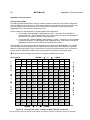
1
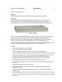
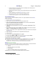
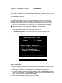
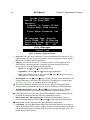
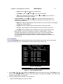
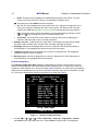
II C UL US 1F61 I.T.E. LISTED Copyright © 2001 Raritan Computer, Inc. MXU2-0B September 2001 Raritan Computer Inc. 400 Cottontail Lane Somerset, NJ 08873 USA Tel. 1-732-764-8886 Fax. 1-732-764-8887 E-mail: [email protected] http://www.raritan.com Raritan Computer Europe, B.V. P.O. Box 566 2900 AN Capelle aan den IJssel The Netherlands Tel. 31-10-284-4040 Fax. 31-10-284-4049 E-mail: [email protected] http://www.raritan.com Raritan Computer Japan, Inc. Kuga Building 7F 11-6, Kuramae 4-chome Taitoo-ku, Tokyo 111-0051, Japan Tel. 81-3-5833-6360 Fax. 81-3-5833-6336 E-mail: [email protected] http://www.raritan.co.jp Raritan Computer Taiwan, Inc. 5F, 121, Lane 235, Pao-Chiao Rd., Hsin Tien Taipei Hsien, Taiwan, ROC Tel. 886-2-8919-1333 Fax. 886-2-8919-1338 E-mail: [email protected] http://www.raritan.com.tw FCC Information MXU2 Manual I FCC Information This equipment has been tested and found to comply with the limits for a Class A digital device, pursuant to Part 15 of the FCC Rules. These limits are designed to provide reasonable protection against harmful interference in a commercial installation. This equipment generates, uses, and can radiate radio frequency energy and if not installed and used in accordance with the instructions, may cause harmful interference to radio communications. Operation of this equipment in a residential environment may cause harmful interference. Product names mentioned in this document are trademarks or registered trademarks of their respective companies. Z-Series, Paragon, MasterConsole MX4, MasterConsole MXU2, MasterConsole II, MasterConsole SMX, and their respective logos are registered trademarks of Raritan Computer, Inc. PS/2, RS/6000, and PC/AT are registered trademarks of International Business Machines Corporation. Mac is a registered trademark of Apple Computer, Inc. Sun is a registered trademark of Sun Microsystems. Alpha is a registered trademark of Compaq Corporation. HP9000 is a registered trademark of Hewlett Packard. SGI is a registered trademark of Silicon Graphics, Inc. All other marks are the property of their respective owners. Japanese Approvals II MXU2 Manual FCC Information Table of Contents MXU2 Manual III Table of Contents FCC INFORMATION ..................................................................................................................................I TABLE OF CONTENTS ...........................................................................................................................III CHAPTER 1. GETTING STARTED ......................................................................................................... 1 Welcome ................................................................................................................................................ 1 Introduction........................................................................................................................................... 1 Features ................................................................................................................................................ 1 Quick Installation and Test ................................................................................................................... 2 MXU2 On-Screen User Interface .......................................................................................................... 2 CHAPTER 2. OPERATING THE MXU2.................................................................................................. 4 Logging In ............................................................................................................................................. 4 Selecting a Computer ............................................................................................................................ 5 User Customization............................................................................................................................... 6 On-Screen User Interface Functions..................................................................................................... 8 CHAPTER 3. ADMINISTRATOR FUNCTIONS..................................................................................... 9 Administration Menu............................................................................................................................. 9 System Configuration ............................................................................................................................ 9 User Configuration ............................................................................................................................. 11 Channel Configuration........................................................................................................................ 12 CHAPTER 4. INSTALLING MXU2 ........................................................................................................ 14 Installations......................................................................................................................................... 14 One-Tier Installation........................................................................................................................... 15 Two-Tier Installation .......................................................................................................................... 16 Prepare Second-Tier MasterConsole MXU2 ...................................................................................... 18 Connect MXU2 Unit for Second-Tier Operation: ............................................................................... 19 Configure Base MXU2 Reserved Channels As Second Tier MXU2 Devices....................................... 20 Connecting Computers to Second-Tier MXU2 Unit(s)........................................................................ 21 APPENDIX A: SECURITY ACCESS ...................................................................................................... 22 Security Access Mode.......................................................................................................................... 22 APPENDIX B: GLOSSARY...................................................................................................................... 24 APPENDIX C: TROUBLESHOOTING .................................................................................................. 27 APPENDIX D: SPECIFICATIONS.......................................................................................................... 29 MXU2 Models ..................................................................................................................................... 29 Universal Cable Kits: For connecting computer to MXU2 or connecting a base MXU2 to a second tier MXU2 ........................................................................................................................................... 29 Accessories.......................................................................................................................................... 29 APPENDIX E: MXU2 AND PARAGON.................................................................................................. 30 Chapter 1. Getting Started MXU2 Manual 1 Chapter 1. Getting Started Welcome Congratulations on your purchase of Raritan Computer’s MasterConsole MXU2. Introduction Raritan's keyboard/video/mouse (KVM) switches are engineered to provide reliable, costeffective, central control of multiple computers. This eliminates the cost and clutter of unnecessary equipment, reclaims space, and improves productivity for a host of applications. Figure 1 MXU2 MXU2 is a 2 user KVM switch that enables up to two simultaneous users to select and operate connected computers. Each user will have exclusive control of any selected computer. Raritan's unique emulation technology dedicates a keyboard and mouse emulator for each computer to ensure that each computer always “sees” its own keyboard and mouse. Each user is provided with an on-screen user interface (OSUI) menu to facilitate operation. The firmware control program can be upgraded via a built-in communication port. Features • Models to connect up to 8 or 16 computers • Direct connect MXU2 to Raritan’s Paragon • Ability to cascade units to control up to 128 computers from 2 user stations. • Locate computers or cascaded units up to 1,000 feet away from the MXU2 using Cat5 Reach • Locate one user station up to 1,000 feet away from the MXU2 with Raritan’s Cat5 receiver— URKVMG receiver included with optional kit (Part number MXU28G orMXU216G). • Tangle proof, double-shielded coaxial cable in lengths of 2, 6.5, 13, 20, and 30 feet • Built in dedicated keyboard and mouse emulators for flawless operation • Includes Keep-alive design to ensure non-stop computer operation in case of power loss to the switch • Supports high-resolution video to 1600 x 1200 • Allows a mix PCs, Macs, Suns, Alphas, RS/6000s, HP9000s, and SGIs with Raritan Guardian converters • Contains a powerful On-Screen User Interface (OSUI) for simple operation and system management • Assign meaningful names to connected computers and select from pop-up, on-screen menus • Stores up to 120 user names, each with personalized operating profile and optional password for security 2 MXU2 Manual Chapter 1. Getting Started • Contains individual user-controlled functions to AutoSkip inactive channels and to AutoScan computers at variable rates • Engineered with multilevel security to ensure authorized access to each computer by each user • Expand capabilities by cascading MXU2 units using 1 or 2 ports. • OSUI supports English, French, and German keyboard layouts • Available firmware upgrades via built-in DB9 administration port Quick Installation and Test Chapter 4 specifies a detailed installation procedure. For a quick installation and test of MXU2, perform the following: 1. Unwrap the MXU2 unit from the packing box. 2. Plug the power cord into the MXU2 and turn the power switch to ON. 3. Plug a user console-keyboard, monitor, and mouse-into the connectors marked keyboard, monitor, and mouse on the back panel of the MXU2. 4. Plug in monitor’s power cord and power on monitor. 5. Login Menu will now be displayed on the monitor. The keyboard’s <Scroll Lock> LED will be blinking. 6. Enter ADMIN as user name, and press <Enter>. Enter ”raritan” (case sensitive) and press <Enter>. The Selection Menu will be displayed on the monitor. 7. Unwrap a universal cable, CCPnn. Plug the DB25 connector into a channel on the back panel of the MXU2 unit. 8. Plug the other end of the cable into a PC’s keyboard/mouse/VGA ports. 9. Power on the PC. 10. The PC channel on the Selection Menu will turn green. 11. Use the keyboard <!> and <"> keys to select the green line, and press <Enter>. 12. You will now be able to operate the PC connected to MXU2. Congratulations! This quick test is complete. # 1To go back to the MXU2 selection menu, press the <Scroll Lock> key twice rapidly. This activates the on-screen user interface. The <Scroll Lock> LED on the user console keyboard blinks, indicating the on-screen user interface has been activated. MXU2 On-Screen User Interface The MXU2 on-screen user interface (OSUI) consists of a simple hierarchy of menus and screens. Each menu (except Login Menu) contains the following sections (Figure 2): • Title Line • Menu/Screen Body (for text and fields) • Help Messages • Status Line (displays Skip/Scan status and OSUI activator) Function keys F1, F2, F4, and F5 switch between different first-level menus. 1 The symbol # provides hints and tips. Chapter 1. Getting Started MXU2 Manual # Pressing <F1> while the on-screen user interface is active invokes the Help Screen. The Help Screen lists all menu options available to the user. # Whenever the on-screen user interface is activated on a user console, that console keyboard’s <Scroll Lock> LED indicator blinks. Menu Title OSUI Main Body Help Messages Status Line Figure 2 OSUI Menu Structure 3 4 MXU2 Manual Chapter 2. Operating The MXU2 Chapter 2. Operating The MXU2 This section describes how a user operates MXU2 functions to access computers. Logging In # You must first login to access the computers connected to the MXU2. When the system is first powered on, the Log-in Menu is displayed on the monitor of each user console. (Figure 3). • Device ID: Name of this MXU2 unit. • User Port: Indicates the physical MXU2 user port to which this user console is currently connected. Please Login Device ID : Base MXU2 User Port : 1 User Name : Password : Help Messages Figure 3 Log-in Menu 1. Enter your user name assigned by your administrator. If user names have not been assigned, there are 5 available defaults − usera, userb, userc, and userd for users, and admin for the administrator (See Chapter 3. Administrator Functions). User names are not case sensitive. 2. Press <Enter>. If a password is necessary, you will be prompted to enter it, and press <Enter> again. Passwords are case sensitive. (See Changing Password on page 8.) 3. The Selection Menu will be displayed (Figure 4 or Figure 5) 4. To go to other menus, use the function keys. (See On-Screen User Interface Functions on page 8.) Chapter 2. Operating The MXU2 MXU2 Manual Selection Menu MC: Base MXU2 Page Ch.ID Name - ------- -----------1 01 Untitled-001 2 02 NT4.0-Mail 3 03 Wins95.Bob 4 04 Wins98.Jack 5 05 Untitled-005 6 06 NT4.0-Susan 7 07 Untitled-007 8 08 Untitled-008 - ------- -----------Help Messages Status Line 5 1/ 1 Stat ----A0 03 A0 03 B0 03 A0 03 A0 03 A0 03 A0 03 A0 03 ----- Figure 4 Selection Menu Selection Menu by Name Page 1/ 1 Name Ch.ID Stat ------------ ------- -----NT4.0-Mail 02 A0 03 NT4.0-Susan 06 A0 03 Wins95.Bob 03 B0 03 Wins98.Jack 04 A0 03 Untitled-001 01 A0 03 Untitled-005 05 A0 03 Untitled-007 07 A0 03 Untitled-008 08 A0 03 ------------ ------- -----Help Messages Status Line Figure 5 Selection Menu by Name Selecting a Computer 1. Activate the on-screen user interface by pressing the <Scroll Lock> twice rapidly. The Selection Menu will be displayed (See Figure 4 & Figure 5). 2. The Selection Menu lists channels sorted either by channel ID (Ch. ID) number (Figure 4) or alphabetically by computer name (Figure 5). Default sorting is by channel ID number. Press <F12> to toggle sorting by—Channel ID Number or Computer Name. • The Selection Menu displays up to eight channels. 6 MXU2 Manual 3. Chapter 2. Operating The MXU2 • The Ch. ID column indicates the physical channel to which each computer is connected. • The Name column lists the computer name. • The Stat column shows each channel's security class on the left side of the column, and the channel-specific scan rate—in seconds—on the right side of the column. (See Channel Configuration on page 12 for instructions on changing a channel’s computer name, security class, and scan rate.) The highlight bar is used to select a channel for connection to the local user console. Each channel’s availability is visually indicated by the following text colors: • Black—no computer connected or computer is powered down • Green—channel is active and available • Red—unavailable, in use by another user • Purple—connected to a second tier unit, first path. • Blue-connected to a second tier unit, second path. • White—current status unknown # If the security class of a channel is shown in red, the channel cannot be selected due to security restrictions. # A small red triangle points to the name of the computer—if any—to which you are currently connected. 4. To select a computer: • Press the <Page Up>, <Page Down>, <!>, or <"> keys to highlight the desired computer and press <Enter>, • Note: When the Selection Menu is sorted by channel ID number, press the desired computer's key number—shown in the left-hand column—and press <Enter>, • Note: When the Selection Menu is sorted by Name—arranged alphabetically— you can type the first character(s) of the desired name to quickly jump to the name that most closely matches the characters you type, and press <Enter>. 5. When you select a computer, you are connected to the active operation at the selected computer. • If you select a MasterConsole device, a list of that device’s channels will display. To return to the base MXU2 Selection Menu press the <Home> key. User Customization The User Profile screen is for displaying a user’s MXU2 configuration and for setting/changing the user’s preferred operating parameters (Figure 6). 1. Activate OSUI by pressing the hot-key <Scroll Lock> key twice rapidly. 2. Press <F4> to access the User Profile screen. • The Connected field displays the name and the channel ID number of the currently selected computer. • The User field displays the User Name entered at login. • The Station field displays the physical MXU2 user port you are connected to. • The Security field displays your security class. • The Admin field displays your administrator privileges. Chapter 2. Operating The MXU2 MXU2 Manual 7 User Profile Connected: Wins95.Bob Ch 3 Name: Susan Station: 1 Security: A0 Admin: Yes Scan Mode: Global Global Scan Rate: 03 Seconds ID Display: On 03 Seconds Green Mode: Off 05 Minutes Hotkey: Scroll Lock Display Position: Menu ID Help Mode: Circ Left Help Messages Status Line Figure 6 User Profile Menu 3. Select the field you want to edit by pressing the <Tab> (forward) <Shift-Tab> (backward) keys to move to the desired field. Press <Enter> to begin the edit. The highlighted area will turn green. When the editing is completed, either press <Enter> to retain the changes or press <Esc> to cancel them. • Scan Mode: Use the <!> and <"> keys to toggle between Global and Individual. The Global Scan Mode scans each channel for the same amount of time, indicated by the Global Scan Rate. The Individual Scan Mode scans each channel for the specified time as shown in the Selection Menu. The default setting is Global. (Setting the channel’s individual scan rate is an administrator function—see page 12.) • Global Scan Rate: Type a number from 01 to 24, or use the <!> and <"> keys to increment or decrement. The default setting is 3 seconds. • ID Display: The ID Display is a small window that shows the computer name and the channel ID number when you switch or scan between channels. It is controlled by two fields: On/Off: Use the <!> and <"> keys to toggle on and off. Time: Type a number from 01 to 24, or use the <!> and <"> keys to increment and decrement. When incremented beyond 24, it displays “ − − “, indicating that the ID window will be shown all the time. The default setting is On/03 seconds. • Green Mode: The Green Mode (PowerSave mode) turns the monitor off if the user console is idle for the specified amount of time. It is controlled by two fields: On/Off: Use the <!> and <"> keys to toggle on and off. Time: Type a number from 01 to 99 or use the <!> and <"> keys to increment and decrement. The default setting is On/05 minutes. • Hot-key: Use the <!> and <"> keys to select <Scroll Lock>, <Caps Lock>, or <Num Lock>. Press the selected hot-key twice rapidly to activate the on-screen user interface. The default setting is <Scroll Lock>. • Display Position: This lets you position the On-Screen menu and ID Display window. Use the <!>, <">, <%> and <&> keys to position the selected window. • Help Mode: Use the <!> and <"> keys to select the preferred help mode. This controls how the help messages are presented on the on-screen user interface menus and screens. The default setting is Circ Left. 8 MXU2 Manual Chapter 2. Operating The MXU2 Multi-Line: Help messages display across the bottom of the On-Screen User Interface, with changing messages in a blinking fashion. Single Line:: Help message is static across the bottom of the On-Screen User Interface. Circ Left: Help messages scroll across bottom of On-Screen User Interface from right to left. Circ Right: Help messages scroll across bottom of On-Screen User Interface from left to right. 4. Changing Password: To add, delete, or change your password, press <P>. You will be prompted to enter your new password of up to eight characters. Press <Enter>, and confirm by re-entering your new password. Then either press <Enter> again to retain the change or press <Esc> to cancel it. 5. Saving Changes: Press <S> to save your changes at any time. When you press <S> or exit the menu, you will be prompted to confirm your changes. On-Screen User Interface Functions Use the following function keys to access MXU2 OSUI functions: Press... When you want to... <F1> access Help; get a list of all of the function keys (Figure 7) <F2> access Selection Menu; view the list of channels, security levels, or scan rates; or select a channel <F4> access the User Profile or view and change user-specific operating parameters <F5> access the Administration Menu if you have administrator privileges <F6> toggle On/Off AutoScan <F7> toggle On/Off AutoSkip <F9> logout <Shift-F9> disconnect from a channel without logging out <F12> while in Selection Menu, toggle sorting by name or channel ID <Esc> Exit # If a user does not have administrator privileges, then the F5 function is displayed in red. Help MXU2 Version: MXU-V2.01 Serial Number: C32B0017 F1 Help / Esc Exit F2 Channel Selection -F12 Sort by Channel/Name F4 User Profile F5 Administrative Functions F6 Toggle Scan On/Off F7 Toggle Skip On/Off F9 Logout -Shft+F9 Release Channel Help Messages Status Line Figure 7 Help Menu Chapter 3. Administrator Functions MXU2 Manual 9 Chapter 3. Administrator Functions This section describes the functions that enable the administrator to configure the MXU2 system so the user can access the computers connected to the MXU2. The functions are performed from a set of administration menus. Administration Menu The Administration Menu is used for setting security classes, maintaining user names and privileges, and managing the system configuration. These tools enable the administrator to control who has access to the MXU2 and which computer resources each user may access. 1. Log in to the system as admin or your user name, if you have administrator privileges. # The default password for the login admin is “raritan” and is case sensitive. 2. The Selection Menu will be displayed. Press <F5> to access the Administration Menu. The Administration Menu displays user port connections (Figure 8). • User Port Connections: User names of the users logged in to each user port. 3. Use the <!> and <"> keys to select the desired submenu, and press <Enter>. Administration Menu User Port Connections 1: Susan 2: Jayson Choose Admin Function - -------------------------1 System Configuration 2 User Configuration 3 Channel Configuration - -------------------------Help Messages Status Line Figure 8 Administration Menu System Configuration The System Configuration menu is used for setting the global parameters that control operation of the system for all users (Figure 9). 1. The System Configuration screen displays the current settings of the parameters. 2. To select the field you want to edit, press the <Tab> (forward) and <Shift-Tab> (backward) keys to move to a desired field. Press <Enter> to edit the field. The highlighted area will turn green. When the editing is completed, press <Enter>. 3. Press <S> to save changes or press <Esc> to cancel them. 10 MXU2 Manual Chapter 3. Administrator Functions System Configuration Device ID: Base MXU2 Security: Timeout: On Logout 05 Min Access Mode: Free Access Allow Blank Password: Yes KB Language Type: English Login Blank: Off 05 Minutes Login Help Mode: Multi-Line User 1-2 Tier: NO NO Help Messages Status Line Figure 9 System Configuration Menu • Device ID: This is the name of the MXU2. Type in the desired name of the device. This gives the device a unique and meaningful name, which is important if you have multiple MXU2 units. The default name is Base MXU2. • Timeout: This is the amount of time—in minutes—before a user is logged out of the MXU2 system or disconnected from a computer, if the user console is idle for that amount of time. The default settings are On/Logout/05. On/Off: Use the <!> and <"> keys to toggle On/Off. Logout/Disc.: Use the <!> and <"> keys to toggle Logout/Disc. Time: Type a number from 01 to 99, or use the <!> and <"> keys to increment or decrement the Time Out time in minutes. • Access Mode: Use the <!> and <"> keys to select one of the four Access Modes: Free Access, Exact Match, Level/Group, and 2-Dgt Level. The default is Free Access. (See Appendix A: Security Access for details about security classes.) # The security classes for individual users can be set in the User Configuration Menu. Security classes for individual channels can be set in the Channel Configuration Menu. • Allow Blank Password: Use the <!> and <"> keys to toggle Yes or No. This field controls whether a user may specify a blank password. The default setting is Yes. # If this field is set to No, a user may not set a blank password. A newly created user has by default no password unless the user or the administrator sets one. • KB Language Type: KB Language Type: The OSUI supports English, French, or German keyboard mapping. Use the <!> and <"> keys to select your keyboard type. # MXU2 power must be recycled for KB Language changes to take effect.. • Login Blank: The Login Blank feature blanks the Login screen after the user console is idle for the specified amount of time in minutes. This acts as a screen saver to protect the monitor. When this screen is blanked, press any key to bring back the Login screen. The default setting is Off/5 minutes. Chapter 3. Administrator Functions MXU2 Manual 11 On/Off: Use the <!> and <"> keys to toggle On/Off. Logout/Disc.: Use the <!> and <"> keys to toggle Logout/Disc. Time: Type a number from 01 to 99, or use the <!> and <"> keys to increment or decrement the Time Out time in minutes. • Login Help Mode: Use the <!> and <"> keys to select the desired help mode. This controls how the help and welcome messages are presented on the Login screen. The default setting is Multi-Line. Multi-Line: Help messages display across the bottom of the Login screen, with changing messages in a blinking fashion. Single Line: Help message is static across the bottom of the Login screen. Circ Left: Help messages scroll across bottom of Login screen from right to left. Circ Right: Help messages scroll across bottom of Login screen from left to right. • User 1-2 Tier: See Two-Tier Installation in Chapter 4. Installing MXU2. Used to designate a specific MXU2 as a second tier unit for user1 or user2 of the base MXU2 unit. This designation must be performed from a separate user console, directly connected to the intended second tier MXU2 unit, prior to installation of the MXU2 as a second tier unit. User Configuration The User Configuration Menu enables the administrator to add, delete, logout, block, and edit user names and security rights (Figure 10). It also displays current connection status for each user. User Configuration User: John Page 1/ 1 Name SC Adm Connection -------- -- --- ------------Admin A0 Yes None Jayson A0 No None Usera A0 No None Userb A0 No None Userc A0 No None Userd A0 No None John A0 Yes Wins95.Bob -------- -- --- ------------Help Messages Status Line Figure 10 User Configuration Menu 1. Use the <!>, <">, <%>, <&>, <Tab>, and <Shift-Tab> keys to move within the menu. Press <Enter> to edit the field. The highlighted area will turn green. When the editing is completed, press <Enter>. Press <S> to save changes or press <Esc> to cancel them. 2. This menu displays user information—one user per line. • User: This field displays your login user name. 12 MXU2 Manual • Chapter 3. Administrator Functions Name: The Name column displays and enables editing of system user names. The user names are not case sensitive. Type up to 8 characters to change a name. # The special user name Admin cannot be changed. • SC: The SC column displays the security class of the user. Typing A-P changes the user’s security level; typing 0-9 changes the user’s security group. The default value of a newly created user is A0. (See Appendix A: Security Access for details about security classes.) • Adm: The Admin column indicates whether the user has administrator privileges. Use the <!> and <"> keys to toggle Yes or No. The default setting is No. • Connection: The Connection column shows the status of each user by displaying the channel to which any active user is currently connected. 3. Adding a new user: To add a new user, press <C>. A new default user name will be added. Proceed to edit the default name, security class, and admin privileges as desired. 4. Deleting a user: Move the highlight bar to a user line, and press <D>. Enter affirmatively to confirm deletion. The highlighted user will be removed from the system. 5. Logging out a user: Move the highlight bar to a user line, and press <L>. The highlighted user will be logged out from the system. 6. Blocking a user: Move the highlight bar to a user line, and press <B>. Enter affirmatively to confirm blocking. The highlighted user will be blocked. Channel Configuration The Channel Configuration Menu enables the administrator to edit the computer names, security classes, and individual scan rates associated with each channel (Figure 11). Any device—such as a computer or another MXU2 unit—can be connected to MXU2 channels. To create a two-tier installation, MXU2 units are cascaded from one or more of the MXU2 channels. (See Two-Tier Installation on page 16.) This section describes the channel configuration for a stand-alone MXU2. Channel Configuration MC: Base MXU2 Page 1/ 1 Ch.ID Name Sec Scn ------- ------------ --- --01 Untitled-001 A0 03 02 NT4.0-Mail A0 03 03 Wins95.Bob B0 03 04 Wins98.Jack A0 03 05 Untitled-005 A0 03 06 NT4.0-Yee A0 03 07 Untitled-007 A0 03 08 Untitled-008 A0 03 ------- ------------ --- --Help Messages Status Line Figure 11 Channel Configuration Menu 1. Use the <!>, <">, <%>, <&>, <Tab>, <Shift-Tab>, <Page up>, <Page down>, <Home>, and <End> keys to move within the menu. Press <Enter> to edit the field. The highlighted Chapter 3. Administrator Functions MXU2 Manual 13 area will turn green. When the editing is completed, either press <Enter> to retain the changes or press <Esc> to cancel them. 2. This menu displays channel information—one computer per line. • MC: This is the name of this MXU2— as named in the Devide ID firel of the System Configuration window. • Ch. ID: This column displays the physical Channel ID number where the device connects to MXU2. • Name: This column displays and enables editing of the computer name. Computer names are case sensitive and may be up to 12 characters. • Sec: This column displays the security class of the computer. Typing A-P changes the computer’s security level; typing 0-9 changes the computer’s security group. The default value of a computer is A0. (See Appendix A: Security Access for detailed explanations of security modes.) • Scn: This column displays the computer’s individual scan rate. Type a number from 01 to 24, or use the <!> and <"> keys to increment or decrement the scan rate. The default setting is 3 seconds. 14 MXU2 Manual Chapter 4. Installing MXU2 Chapter 4. Installing MXU2 Installations MasterConsole MXU2 can be installed to control 8 or 16 computers in a one-tier installation with 2 simultaneous users. To expand computer capacity, the MXU2 can be cascaded with other MXU2 units to create a two-tier installation that controls up to 128 computers with unblocked access. MasterConsole MXU2 User Figure 12 One-Tier Configuration On/Off Admin Serial Port AC IN 0.6A AC POWER 100V-240V 47Hz-63Hz Power Supply Mouse Admin. 2 4 6 1 3 5 Default Setting Monitor User2 Keyboard User1 6-pin mini-DIN Female & HD15 Female to User Console User2 RJ45 Cat 5 cable to Cat5 Receiver and User Console Figure 13 Back of MXU2 8 Chapter 4. Installing MXU2 15 MXU2 Manual One-Tier Installation In a one-tier installation, computers are connected to a single MXU2 unit (Figure 12). Complete the following steps for a one-tier installation: 1. Shut down and power off all computers and monitors to be connected to the MXU2. 2. Install user console(s) to the MXU2. a) User 1 - Local User Console: Connect Local User Console 1 to MXU2 Mouse (Male) Keyboard (Male) Plug in monitor’s power cord Video (HD15M) Back of MXU2 Figure 14 • • Install Local User Console 1 to MXU2 Connect user console to appropriate ports on back of MXU2 – keyboard to port labeled “Keyboard” (6-pin mini-DIN Female), mouse to port labeled “Mouse” (6-pin mini-DIN Female), and monitor to port labeled “Monitor” (HD15 Female). Plug in monitor power cord and turn on monitor. b) User 2 - Remote User Console (up to 1,000 feet away): Figure 15 Install Remote User Console 2 to MXU2 16 • • • • • MXU2 Manual Chapter 4. Installing MXU2 Plug the DC Adapter (Part # A10D1-06MP) into the URKVMG and the other end into an AC power outlet. Connect a keyboard, monitor, and mouse (user console) to appropriate 6-pin mini-DIN Female keyboard and mouse ports, and HD15 Female ports on Cat5 Receiver (URKVMG). Plug in monitor power cord and turn on monitor. Connect Category 5 cable to RJ45 port on URKVMG. Connect the other end of the Category 5 cable to the RJ45 User 2 port on the back of the MXU2. 3. Power on the MXU2 unit. • Connect power cord to back of MXU2 unit and AC power outlet. • Power ON the MXU2 via the power switch on the back of the unit • The Login Menu will be displayed on the monitor. The default name usera automatically appears in the user name field of the Login Menu. • Press <Enter>. The Selection Menu will be displayed (Figure 4). 4. Connect computer(s) to the MXU2 • Plug the DB25 male end of a CCPnn cable into one of the numbered DB25 female ports on the MXU2 back panel (Figure 13). Each numbered DB25 female port on the back of the MXU2 represents a channel on the Selection Menu. • Plug the connectors on the cable’s other end into the computer's keyboard, monitor, and mouse ports. • Power on the connected computer. • On the Selection Menu, the line displaying the channel where the new computer has been connected will turn green. • Use the <!> and <"> keys to select the channel, and press <Enter>. • You will now be able to operate the computer just as if the keyboard, monitor, and mouse were connected directly. • Press <F5> to access the Administration Menu. # You must login to the base MXU2 as an administrator to access the Administration Menu and perform administrative configuration menu operations. • Select option number 3—Channel Configuration. • Using the <!> and <"> keys, highlight the channel on the MXU2 to which you have just connected a second tier computer. • Press the G key—on the keyboard—to select this computer for channel editing. • Edit the name of the computer on the second tier. • Enter S to save and then Y to confirm changes, or N to re-edit. Or enter Esc to cancel. 5. Repeat step 4 to connect remaining computers to the MXU2. Two-Tier Installation In a two-tier installation, the second tier MXU2 unit is connected to channel(s) on the base MXU2. Each DB25 port represents a selection channel. One channel or DB25 female port on the back of the base MXU2 can be connected to the second tier MXU2. For unblocked access, two vertically grouped, consecutive DB25 female ports on the base MXU2 should be connected to the second tier MXU2 For a two-tier installation, details to the steps outlined below are given on the following pages. Chapter 4. Installing MXU2 MXU2 Manual 17 1. Install base unit – first tier – MasterConsole MXU2, reserving channel(s) for each second tier MXU2 to be connected. 2. Prepare second tier MasterConsole MXU2 unit(s). 3. Connect MXU2 unit(s) for second tier operation. 4. Configure base MXU2 reserved channels as second tier MXU2 devices. 5. Connect computers to the second tier MXU2 unit(s). Figure 16 Two-Tier Configuration Install Base Unit—First-Tier—MasterConsole MXU2 1. Follow the One-Tier installation procedure to set up the base MXU2 with the following exception: • Reserve 1 channel, or 2 vertically consecutive channels, for each second tier MXU2 unit. # Unblocked access to second tier computers, where two users can access second tier computers simultaneously, is recommended. For unblocked access, two vertically consecutive channels should be reserved - 1-2 or 3-4 or 5-6 or 7-8 etc… - for each second tier MXU2 unit to be connected. 18 MXU2 Manual Chapter 4. Installing MXU2 Prepare Second-Tier MasterConsole MXU2 Each MXU2 that will be used as a second tier unit must first be separately programmed for tier mode: 1. Attach a user console to the MXU2 unit that will be used as a second tier unit. • • Connect user console to appropriate ports on back of MXU2 – keyboard to port labeled “Keyboard” (6-pin mini-DIN Female), mouse to port labeled “Mouse” (6-pin mini-DIN Female), and monitor to port labeled “Monitor” (HD15 Female). Plug in monitor power cord and turn on monitor. 2. Powering on the MXU2 and login. • Connect power cord to back of MXU2 unit and AC power outlet. • Power ON the MXU2 via the power switch on the back of the unit. • The Login Menu will be displayed on the monitor. • Enter admin in the user name field of the Login Menu, and press <Enter>. Enter raritan in the password field, and press <Enter>. The Selection Menu will be displayed (Figure 4). 3. Setting up the MXU2 as a second tier unit. • At the Selection Menu press <F5>. The Administration Menu will appear. • Highlight selection number 1 – System Configuration – and press <Enter>. The System Configuration Menu will appear. • On the System Configuration menu, set each second tier user port to Yes. Press the <Tab> (forward) and <Shift-Tab> (backward) keys to move to the User 12 Tier: field. The first entry in this field applies to user port 1, and the second entry applies to user port 2. Press <Enter> to edit each user tier field. The highlighted area will turn green. Use the <!>, <">, <%>, or <&> keys to select Yes for each user port that will be connected as a second tier. When the editing is completed, press <Enter> and the field will turn yellow. Press <S> to save the changes. # Unblocked access to second tier computers, where two users can access second tier computers simultaneously, is recommended. For unblocked access, two vertically consecutive channels should be reserved - 1-2 or 3-4 or 5-6 or 7-8 etc… - for each second tier MXU2 unit to be connected. 4. The MXU2 is now programmed for second tier use. 5. Power off the MXU2 via the power switch in the back of the unit. 6. Disconnect the user console from this MXU2 second tier unit. 7. Repeat steps 1 through 6 for each MXU2 that is to be designated as a second tier unit. Chapter 4. Installing MXU2 MXU2 Manual 19 Connect MXU2 Unit for Second-Tier Operation: Connect Second Tier MXU2 to Base MXU2 Plug in UKVMG Category 5 Cable Back of Base MXU2 Figure 17 Connect Second Tier MXU2 Unit to Base MXU2 # Each MXU2 that will be used as a second tier unit must first be separately programmed for tier mode. See prior steps under Prepare Second Tier MasterConsole MXU2 for instructions. 1. Power off the base MXU2. # If computers have already been connected to the base MXU2 unit, you do not have to shut down the computers; because even when the MXU2 is powered off, its keyboard/mouse keep-alive feature continues performing keyboard/mouse emulation on attached computers. 2. Power off all second tier MXU2 units before connecting them to the base MXU2. 3. Connect reserved channel(s) on the base MXU2 unit to user port(s) on the back of the second tier MXU2. # Unblocked access to second tier computers, where two users can access second tier computers simultaneously, is recommended. For unblocked access, two vertically consecutive channels should be reserved - 1-2 or 3-4 or 5-6 or 7-8 etc… - for each second tier MXU2 unit to be connected. • Connect the reserved channel on the base MXU2 unit to the RJ45 User 2 port on the back of the second tier MXU2 unit Plug the DC Adapter (Part # A10D1-06MP) into the URKVMG and the other end into an AC power outlet. Using a CCPnn cable, plug the male keyboard, video, and mouse connectors into the appropriate 6-pin mini-DIN and HD15 female ports on the Cat5 Receiver (URKVMG). 20 MXU2 Manual Chapter 4. Installing MXU2 On the other end of the CCPnn cable, plug the DB25 connector (male) into the DB25 (female) reserved channel on the base MXU2 unit. Connect the Category 5 cable into the RJ45 port on the URKVMG. Connect the other end of the Category 5 cable into the RJ45 User 2 port on the back of the second tier MXU2 unit. • Connect the reserved channel on the base MXU2 unit to the user 1 on the back of the second tier MXU2 unit. Using a CCPnn cable, plug the DB25 connector (male) into the DB25 (female) reserved channel on the base MXU2 unit. Plug the male keyboard, video, and mouse ports on the other end of the CCPnn cable into the appropriate 6-pin mini-DIN and HD15 female ports on the back of the second tier MXU2 unit. 4. Repeat steps 2 through 3 for each second tier MXU2 unit. Configure Base MXU2 Reserved Channels As Second Tier MXU2 Devices Channel configuration must be performed from the Administration Menu of the base MXU2 for each second tier MXU2 channel connected to the base. 1. Power on all second-tier MXU2 units. • Connect power cord to back of all second tier MXU2 units and AC power outlet. • Power ON each second tier MXU2 via the power switch on the back of the unit. # To guarantee correct operation, always power on all second-tier MXU2 units before the base unit. 2. Power on the base MXU2 and login. • Power ON the base MXU2 via the power switch on the back of the unit. • The Login Menu will be displayed on the monitor. • Enter admin in the user name field of the Login Menu, and press <Enter>. Enter raritan in the password field, and press <Enter>. The Selection Menu will be displayed (Figure 4). # You must login to the base MXU2 as an administrator to access the Administration Menu and perform administrative configuration menu operations. 3. Press F5 to access the Administration Menu. 4. Select the Channel Configuration submenu, and press <Enter>. 5. Use the <!> and <"> keys to highlight the reserved channel now connected to a second-tier MXU2. 6. Press <C> to display the Device Configuration screen 7. From the list of devices, select the appropriate device (MXU2) and press <Enter>. The next level of the Device Configuration menu will be displayed 8. From the list of device sizes, select the appropriate number of channels (8 or 16) for the connected second tier MXU2 unit and press <Enter>. 9. Select the number of paths to the second tier MXU2 unit and press <Enter>. 10. The display will return to the Channel Configuration menu (Figure 11). 11. The configured channel(s) will now be displayed in a different color on the menu to indicate that they are paths to the second tier MXU2. The first path channel will display in purple, and each second path channel will display in the color blue. 12. Repeat steps 5 through 11 for each connected second tier MXU2. 13. Press <F2> to bring up the base MXU2’s selection menu and confirm that all new MXU2 devices are displayed in purple/blue on the proper channel(s) in the Selection Menu (Figure 4). Chapter 4. Installing MXU2 MXU2 Manual 21 Connecting Computers to Second-Tier MXU2 Unit(s) 1. Plug the DB25 male end of a CCPnn cable into one of the numbered DB25 female ports on the second tier MXU2 back panel. Each numbered DB25 female port on the back of the MXU2 represents a channel on the Selection Menu. 2. Plug the connectors on the cable’s other end into the computer's keyboard, monitor, and mouse ports. 3. Power on the connected computer. 4. On the Selection Menu <F2>, the line displaying the channel where the new computer has been connected will turn green. 5. Use the <!> and <"> keys to select the channel, and press <Enter>. 6. You will now be able to operate the computer just as if the keyboard, monitor, and mouse were directly connected directly. 7. Press <F5> to access the Administration Menu. # You must login to the base MXU2 as an administrator to access the Administration Menu and perform administrative configuration menu operations. 8. Select option number 3—Channel Configuration. 9. Using the <!> and <"> keys, highlight the channel on the second tier MXU2 to which you have just connected a second tier computer. 10. Press the G key—on the keyboard—to select this computer for channel editing. 11. Edit the name of the computer on the second tier. 12. Enter S to save and then Y to confirm changes, or N to re-edit. Or enter Esc to cancel. 13. Repeat steps 1 through 12 to connect remaining computers to the second tier MXU2 unit. 22 MXU2 Manual Appendix A: Security Access Appendix A: Security Access Security Access Mode The MXU2 provides administrators with four modes of security access (set in the System Configuration menu) in addition to the login security. These modes determine how the user’s security class (set on the User Configuration menu) permits access to computers that are assigned channel security class designations (set on the Channel Configuration menu). Security classes are represented by a two digit alphanumeric designation. ' The first digit, called the level, is designated by a letter. Letters A to P are available to represent the level. A is the highest level and P is the lowest level. As the level designation proceeds from A towards P, security access decreases. ' The second digit, called the group, is designated by a number. Numbers 0 to 9 are available to represent the group. 0 is the highest group designation and 9 is the lowest. As the group designation proceeds from 0 towards 9, security access decreases. Taken together, the entire security class is represented by the designation [level group]. For example, A0 is the highest security class and P9 is the lowest security class. As you move from left to right and down the security class table (Figure 18) from A0 to P9, security access decreases. So a user with the security class B5 would have broader, higher access than a user with the security class of M8. # Users with admin privileges can access any computer regardless of the mode. AO is highest HIGHER ⇒ ⇒ to LOWER A0 A1 A2 A3 A4 A5 A6 A7 A8 A9 H I G H E R B0 B1 B2 B3 B4 B5 B6 B7 B8 B9 C0 C1 C2 C3 C4 C5 C6 C7 C8 C9 D0 D1 D2 D3 D4 D5 D6 D7 D8 D9 E0 E1 E2 E3 E4 E5 E6 E7 E8 E9 ⇓ F0 F1 F2 F3 F4 F5 F6 F7 F8 F9 G0 G1 G2 G3 G4 G5 G6 G7 G8 G9 ⇓ H0 H1 H2 H3 H4 H5 H6 H7 H8 H9 to I0 I1 I2 I3 I4 I5 I6 I7 I8 I9 ⇓ J0 J1 J2 J3 J4 J5 J6 J7 J8 J9 K0 K1 K2 K3 K4 K5 K6 K7 K8 K9 L0 L1 L2 L3 L4 L5 L6 L7 L8 L9 M0 M1 M2 M3 M4 M5 M6 M7 M8 M9 N0 N1 N2 N3 N4 N5 N6 N7 N8 N9 O0 O1 O2 O3 O4 O5 O6 O7 O8 O9 P0 P1 P2 P3 P4 P5 P6 P7 P8 P9 HIGHER ⇒ to ⇓ L O W E R Figure 18 to ⇒ LOWER H I G H E R L O W E R P9 is lowest Security Class Table – Example of What a D5 User Can Access Gray represents 2 Digit Level Security Access Mode & black boxes represent Level/Group Security Access Mode Appendix A: Security Access MXU2 Manual 23 1. Free Access: All users have free access to all channels. The only security is the login user name and password—if used. Setting security classes have no effect when this mode is invoked. Free Access is the default setting. 2. Exact Match: The user’s security class must be exactly the same as the channel security class in order for the user to access the channel. • Example: If the user’s security class is B1, then they will be able to access only the computer with the channel security class of B1. All other computers with security class settings other than B1 will not be accessible in Exact Match security mode. 3. 2 Digit Level: Once a user’s security class is designated, that user can access all computers that have equal or lower channel security class designations. ( Example: User’s security class = D5. User can access channel D5 and all lower channels D6 through P9 (Figure 18). 4. Level/Group: Once a user’s security class is designated, that user can access a computer: • with the exact same security class designation • with a lower level (letter) channel security class designation • with the same level (letter) designation and the group zero. ( Example: User’s security class = D5. User can access channel D5, all lower levelsE0 through P9, and D0 (Figure 18) . Appendix B: Glossary • Administration Menu For installing and configuring access to the MXU2. Use is restricted to those with administrator privileges. • AutoScan When activated, the MXU2 automatically cycles through channels, displaying each computer's video for a specified time interval. • AutoSkip When activated, channel selection is restricted to active channels. • Base Unit The MXU2 unit to which computers and/or other MasterConsole units are connected in a twotier configuration. • C Model MasterConsole II models MCC4, MCC8, and MCC16. • Channel The 25-pin connector identifying where a device is connected to the MXU2. There are 8 channels on model MXU28 units, and 16 channels on model MXU216 units. • Active: A channel is active when a connected device is powered on. • Inactive: A channel is inactive if no device is connected to it or if the connected device is powered off. • Channel Configuration Menu For editing computer and device names, changing security classes, and assigning channelspecific scan rates. • Channel ID Number The specific channel number to which a device is connected. • Computer Name A label of up to 12 characters assigned by an administrator for a device connected to an MXU2 channel. • Configuration One-Tier: Only computers are connected directly to a single MXU2 unit Two-Tier: A mix of devices—computers and MasterConsole units—are connected to a base MasterConsole unit. • Device A computer or any MasterConsole unit connected to an MXU2 channel. • Green Mode A field in the User Profile Menu for toggling the PowerSave feature on and off at a specified time interval. • Hot-key For activating the on-screen user interface. To activate the on-screen user interface, press the hot-key—default <ScrollLock>—twice rapidly. • ID Display A single-line display shown on the monitor to identify the currently selected channel. • Key Number Located in the left-hand column of the Selection Menu in red. To quickly select a channel, press the corresponding key number on the keyboard when the Selection Menu is displayed. • Logging In Entering a user name to gain access to the MXU2 system. 255-27-0001 Appendix B: Glossary MXU2 Manual 25 • Login Screen For logging in to the system as a user or administrator. • Logout Logs a user out of the system. • Menu An MXU2 on-screen user interfaces display. • Menu F Keys Function keys used for accessing on-screen user interface menus. • Password Used in conjunction with user name to gain access to the MXU2. • PowerSave Allows a properly equipped monitor to operate in energy save mode. See also Green Mode. • Remote KVM Module Unit that enables the MXU2 to connect to computers or user consoles up to 1000 feet away. • Reserved Channels In a two-tier configuration, the channels on the base MXU2 unit allocated to connect secondtier MasterConsole(s). • S Model MasterConsole II models MCS4 and MCS8. • Scan Mode Field in the User Profile; can be set to either Global or Individual. See also Scan Rate. • Scan Rate The time interval—in seconds—that a channel's computer is to remain displayed on the monitor when AutoScan is activated. • • Global Scan Rate: The scan rate used for all channels when the Scan Mode field in the User Profile is set to Global. • Channel-Specific (Individual) Scan Rate: Scan rate specified for each channel when the Scan Mode field in the User Profile is set to Individual. Channel-specific scan rates are set in the Channel Configuration submenu of the Administration Menu. Security Code Letter/number set assigned to each user and computer to establish user-access rights. • Class: Refers to the entire security code (A0). • Level: Refers to the letter in the security code (A0). • Group: Refers to the number in the security code (A0). • Selection Menu For selecting a computer or device. • Sorting Order of the channels listed in the Selection Menu—either by channel ID or by name. Pressing F12 toggles the sort criterion when a Selection Menu is displayed. • System Configuration For allowing and disallowing blank passwords, turning Time Out on and off, changing the Time Out interval, turning the Login Screen on and off, and changing the Login interval. • Time Out Length of time that a user port can remain idle since the previous keyboard/mouse operation before the connected console is automatically logged out. User must enter an authorized user name and password to re-establish access after Time Out. • User Configuration Used by the administrator for adding, deleting, and changing user names, security codes, and administrator privileges. • User Console The keyboard, monitor, and mouse plugged into a user port on the MXU2 back panel. • User Name Name a user types to log in to the system. • User Port Where a user console (keyboard, monitor, and mouse) is connected to an MXU2. • User Profile For setting and changing user passwords and preferences. • X Model MasterConsole II models MCX4, MCX8, and MCX16. Includes Port Out for connecting a Remote Access Kit. 255-27-0001 Appendix C: Troubleshooting MXU2 Manual 27 Appendix C: Troubleshooting 1. No power. (a) Check power cord and make sure power switch is turned on. (b) Check cable connection from computer to MXU2. (c) MXU2 power supply has built-in surge protection. If you cannot regain power during a power recycling process, power off the unit. Wait for 15–20 seconds, and then turn on again. 2. No video display for one or all computers. (a) Check video cable's connection to the computer. (b) Check the monitor and computer. Turn off the power to MasterConsole and computers. Connect the monitor to the computer directly, boot the computer and make sure the monitor has the proper display. If it does not, either the problem is with your computer or the monitor is not compatible with your computer. If it does display, continue to Troubleshooting item 3. 3. The monitor cannot correctly display the video output for some of the computers. (a) The monitor probably does not match the video outputs. If the monitor is a single-modetype VGA, all computers must have the same type of video output. 4. All computers powered up without keyboard error, but the keyboard at MXU2 has no control—cannot input to any computer. (a) Make sure the keyboard is connected firmly into the MXU2 keyboard port. (b) Replace keyboard. MasterConsole allows hot reconnection of the keyboard at its user console port. (c) In a two-tier configuration, check that the MXU2 with the keyboard connected is the base unit. 5. Repeated "KB ERROR" at computer power-up. (a) The keyboard cable from the computer to the MXU2 is loose. Secure the connection and power up the computer again. (b) If the problem occurs after the MXU2 has been installed for a period of time and occurs on computers that have previously worked with MXU2, then some components are out of order. Verify that the computer works with the keyboard when connected directly. Then contact your dealer or Raritan Computer Technical Support for service. 6. After a period of trouble-free operation, the keyboard attached to the MXU2 locks— unable to input keystrokes—when a particular computer is selected, but works normally when other computers are selected. (a) The most likely cause of the problem is either a voltage spike—increase— or a brownout—decrease—in the power supply, which would cause the microprocessors in the MXU2 to malfunction. A short-term solution to the problem is to try to recover operation by turning the MXU2's power switch off and on. Then, if necessary, restart all computers. The long-term solution to avoid this problem is to power the MXU2 from a UPS. (b) Check keyboard connection. 7. Repeated "MOUSE INSTALLATION FAILURE" at computer power-up. (a) The mouse cable from the computer to the MXU2 is loose. Secure the connection, and power up again. (b) If the problem occurs only with new computers that are being added to the system, the firmware in the KVM—an internal mouse emulator—may need to be upgraded to a later version to be compatible with newer computers. Contact your dealer or Raritan Computer Technical Support for service. 8. After a period of trouble-free operation, the mouse attached to the MXU2 locks— unable to control mouse functions—when a particular computer is selected, but works normally when other computers are selected. (a) Try to identify whether the problem is originating from the computer by reconnecting the computer to a different channel with a different cable. Then power up the computer. If the problem is not with the cable or with the specific channel, then connect the mouse directly to the computer. If the problem persists, then the computer's mouse port is out of order. Otherwise, contact your dealer or Raritan Computer Technical Support. (b) If the problem occurs after the MXU2 has been installed for a period of time and occurs to computers that have previously worked with the MXU2, then some components are out of order. Contact your dealer or Raritan Computer for service. 9. Unit does not operate in on-screen user interface mode. (a) Replace keyboard. OSUI works only with PS/2 or extended AT-style keyboards. 255-27-0001 Appendix D: Specifications 29 MXU2 Manual Appendix D: Specifications MXU2 Models MXU2 MXU2 8-channel model 16-channel model Dimensions 15.4"(W) x 8.0"(D) x 1.7"(H) 15.4"(W) x 8.0"(D) x 3.5"(H) Weight 2.4 kg (5.3 lb.) 3.2 kg (7.2 lb.) Power 100V/240V Auto Sensing 100V/240V Auto Sensing 47 Hz / 63 Hz 0.6A/0.3A 47 Hz / 63 Hz 0.6A/0.3A 0–50°C (32-122°F) 0–50°C (32-122°F) Operating Temperature Universal Cable Kits: For connecting computer to MXU2 or connecting a base MXU2 to a second tier MXU2 Part No. Length Connectors CCP06 2' (0.6 M) DB25(M) to HD15(M), 2x mini-DIN6(M) CCP20 6.5' (2 M) DB25(M) to HD15(M), 2x mini-DIN6(M) CCP40 13' (3 M) DB25(M) to HD15(M), 2x mini-DIN6(M) CCP60 20' (6 M) DB25(M) to HD15(M), 2x mini-DIN6(M) CCP90 30' (9 M) DB25(M) to HD15(M), 2x mini-DIN6(M) Adapters for AT-style keyboard and serial mouse: (1) DIN 6F to DIN 5M and (1) DIN 6F to DB9F can be order for each CCPnn cable. Use Raritan part number: APSAT Accessories Cat5 Reach Cat5 Reach extends the keyboard, mouse and monitor, computers, and cascaded units up to 1000 feet apart by means of a Category 5 UTP cable. The product consists of a transmitter/receiver pair. Category 5 UTP cable not included. Extended Cable Kits Extends the keyboard, mouse and monitor, computers, and cascaded units up to 325 feet with a coaxial cable. The product consists of a transmitter, receiver, and cable. RMXU2-1U 19" Rack Mount Bracket (for MXU28)—1U RMXU2-2U 19" Rack Mount Bracket (for MXU216)—2U APSMAC Converter for Mac (Mac ADB and video to PS/2 k/b, PS/2 mouse, and VGA ports) APSSUN Converter for Sun (Sun k/b and video to PS/2 k/b, PS/2 mouse, and VGA ports) ASOGVGA Sync on green converter for HP9000 or SGI with HD15 video ASGIVGA Sync on green converter for SGI with 13W3 video ARSVGA Sync on green converter for RS/6000 with 13W3 video APSUSB USB to PS/2 converter AUATC ASCII Terminal Converter (serial to PS/2) Appendix E: MXU2 and Paragon The MXU2 can be connected directly to a Paragon (UMT8) channel from the RJ45 user port. This will enable clustered access to all servers connected to the MXU2 from any user logged into the Paragon system. If a second user access path is required, the local KVM ports can be connected to a UMT8 main switching unit with the use of a UKVMP (CIM). The diagram below (Figure 19) shows the configuration options available for connecting the MXU2 directly to the UMT8 with either one or two user paths. Please refer to the Paragon Administrators Installation and Users Guide for menu option settings to enable the access of servers connected to the MXU2. When the MXU2 is used as a cluster access device from the Paragon, please refer to the Prepare Second-Tier MasterConsole MXU2 section on page 17 of this manual. One path Figure 19 255-27-0001 Two paths Connect MXU2 Directly to Paragon UMT8