1
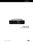
Holley EFI Digital Dash
User Manual
CONTENTS
Introduction ................................................................................................................... 4
Quick Start Guide.......................................................................................................... 5
Package Contents......................................................................................................... 5
Specifications................................................................................................................ 5
General ...................................................................................................................... 5
Mounting .................................................................................................................... 6
Connectors................................................................................................................. 7
CAN1/Power ........................................................................................................... 7
USB......................................................................................................................... 7
CAN Adapter Harness ............................................................................................. 7
Using the Dash ............................................................................................................. 8
Touchscreen Basics ................................................................................................... 8
Main Menu ................................................................................................................. 8
Configuration ........................................................................................................... 8
Data Log.................................................................................................................. 9
Utilities .................................................................................................................. 10
Customize ............................................................................................................. 10
About..................................................................................................................... 10
Dashboard............................................................................................................. 10
Customizing Your Layout ............................................................................................ 10
Import/Export ........................................................................................................... 10
Adding Gauges ........................................................................................................ 11
Gauge Types ......................................................................................................... 11
Customizing the Gauge ............................................................................................ 14
Adding Labels .......................................................................................................... 23
Adding Switches ...................................................................................................... 23
Changing the Background ........................................................................................ 25
Saving Your Layout .................................................................................................. 26
2
Start-up Gauge Layout ............................................................................................. 26
Preconfigured Layouts ................................................................................................ 27
Modifying Channels on a Preconfigured Layout ....................................................... 28
Data Log Playback ...................................................................................................... 29
Cleaning ..................................................................................................................... 29
Appendix A ................................................................................................................. 30
Appendix B ................................................................................................................. 31
Increasing Internal Logging Storage (micro-SD card) ............................................ 31
Optional I/O Connector .......................................................................................... 32
Appendix C ................................................................................................................. 33
3
Introduction
The Holley EFI Digital Dash is completely customizable with a variety of gauge and indicator screens that can
be programmed to display any parameter you need. Users can select from pre-configured layouts, or
personalize their own. The dash also offers a virtual switch panel, user defined alarms, configurable shift lights
and can control on-screen playback of your EFI data logs. This all new Holley EFI Digital Dash claimed the
SEMA New Product Award for Best Engineered New Product 2015.
The Holley EFI Digital Dash measures 7.5" wide, 4.625" tall and 1" deep, making it a compact, customizable
dash for use in a variety of motorsports applications. The Dash features a 7" low glare, high brightness, high
contrast, full color touch screen for easy viewing even in full sun, plug and play connection to all Holley EFI
systems as well as a weather proof aluminum housing featuring flexible mounting options. Monitor the power of
your Holley EFI system at a glance!
4
Quick Start Guide
A CAN/power harness is supplied with the digital dash. Connect the black wire to negative, white wire to a
switched +12V circuit.
Connect the harness from the CAN connector on the vehicles main harness to the digital dash using the
supplied 4’ CAN/Power extension
Once all connections have been made the Holley EFI Digital Dash may be powered up. After a brief initial
loading sequence the gauge display will appear.
Package Contents
Specifications
General
·
·
·
·
·
·
·
·
·
·
·
·
·
·
·
·
·
·
·
·
Weather-proof aluminum housing engineered to withstand harsh racing environments
7” Low Glare, High Brightness, High Contrast, Full Color Touchscreen
800x480 Resolution
Operating voltage min 8V - 20V
Auto Brightness
Plug and Play connection with all Holley EFI systems via CAN bus
Completely customizable display of all EFI parameters including every user configured input and output
Multiple gauge and indicator types with limitless customization options
Quickly toggle between two or more active screens (tune, warm-up, race, drive, etc.)
Virtual switch panel
User defined channel alarms
Configurable progressive shift lights and light bar
On screen playback of EFI data logs
Download and save Holley EFI data logs to external USB memory stick
Expandable internal storage on micro SD card
Flexible mounting options
Support for future USB devices
Upgradable with future software/firmware enhancements
Multiple units can be used simultaneously on a Holley EFI system for larger dashboards
Internal 3-axis accelerometer (will require update available February 2015)
5
Mounting
The product has eight tapped 8-32 mounting holes to allow the user to surface mount or flush mount the
enclosure. There are four mounting holes located on the rear of the unit, and two mounting holes are located
on the left and right sides. Included with the contents of this kit is a separate template with a 1:1 layout of hole
locations for fabricating a mounting bracket.
NOT TO SCALE – USE THE TEMPLATE INCLUDED IN YOUR KIT
6
Connectors
CAN1/Power
4 pin Mizu-P25 male receptacle connector used to connect main power and to a Holley EFI. The dual
connector allows the product to be connected to multiple devices on the CAN bus.
Pin
1
2
3
4
Function
+12V
CAN1H
CAN1L
GND
Color
WHT
ORG/BLK
ORG
BLK
Description
Main power in
CAN_H Holley EFI communications
CAN_L Holley EFI communications
GND
USB
The unit has two standard USB type A receptacles that can accept USB flash drives for saving data logs,
uploading gauge screen layouts, background images, or firmware updates.
CAN Adapter Harness
271R1075A CAN ADAPTER HARNESS - used to connect switched +12V ignition power (white wire)
and ground (black wire) to the dash, as well as for connecting to the main harness CAN connector.
7
Using the Dash
Touchscreen Basics
The Holley EFI Digital Dash has been designed with a resistive touchscreen, meaning it will work with bare
skin, a stylus, or even through driving gloves. This dash responds to localized point pressure on the screen,
not ‘swiping’, which is common on capacitive screens found on current smart phones and tablets.
Main Menu
Pressing anywhere on a gauge screen will bring up the navigational buttons. To access the main menu
choose ‘Menu’ in the upper right corner of the screen.
Configuration
The configuration screen allows you to change the display brightness, modify the number of gauge display
layouts (screens), update firmware, and calibrate the touchscreen if required.
Screen
You may choose the number of layouts or gauge display screens that are configured. An example would be 4
screens, representing tuning, warm up, race, and street.
The Dash will use the last saved layout as the preferred screen to display at power on.
8
Auto Brightness
The Dash has an ambient light sensor at the lower left corner of the display. This sensor is used to set the
backlight brightness when auto brightness is enabled. If this sensor is covered, the auto brightness feature
will not function.
Press on the “Auto” beside brightness to enable the auto-brightness function. For manual brightness control,
use the slider to adjust the screen brightness.
Firmware Upgrade
New or additional features developed by Holley can be added to the Digital Dash by updating firmware. These
updated firmware files can be obtained by contacting tech service (270-781-9741 or 1-866-464-6553) or they
may be downloaded from our website (https://www.holley.com/support/resources/) under the fuel injection tab.
To perform a firmware update, follow these steps:
1. Copy the firmware file onto a USB memory stick
2. Connect the USB memory stick to one of the USB cables on the Digital Dash.
a. If the unit is off, the firmware update will take place automatically as soon as the Dash is
powered on with the USB stick plugged in. No further action is required.
b. If the dash is already powered on, proceed to step 3
3. Select ‘Update Firmware’ from the Configuration menu and follow the on screen prompts.
Data Log
The Holley EFI Digital Dash allows you to retrieve, delete and configure data logging with the attached HEFI.
Data logs can be saved internally or to a USB memory stick for viewing on a computer.
9
Utilities
The utilities screen allows users to perform file functions such as deleting files and copying files to USB
memory sticks.
Customize
Select this button to enter gauge customization mode. These functions are covered later on in the manual.
About
This screen contains firmware and software version information along with the CAN id for the Digital Dash.
When connected with a Holley EFI it will show details of the connected EFI.
Dashboard
This selection returns you to the operational dash layout.
Customizing Your Layout
Choosing ‘Customize’ from the Main Menu enables the gauge customization mode. Entering this mode will
allow any of the preconfigured layouts to be modified, or one may be built from scratch.
Import/Export
The import function will load any saved gauge layout (.ini file) to the active screen. The export function will
allow any gauge layout to be saved internally or to a USB Memory Stick. Preconfigured layout examples and
filenames are outlined later in this manual.
To begin building a custom layout from a blank template, touch any bare area of the background.
Choose Layout > Import > Clear
10
Adding Gauges
Press on the display where you want a gauge to appear, then click Add > Gauge > Value to Monitor > Gauge
Type. Once you have selected the gauge type you will be asked to select the value to monitor. Every
available EFI channel including user configured inputs and outputs will be shown in this list (see Appendix A).
Once the value is chosen the gauge will be placed on the screen.
1. Select ‘Add’
2. Select ‘Gauge’
3. Select Value to Monitor
4. Select Gauge type
Step 1
Step 2
Step 3
Step 4
Gauge Types
See page 13 for pictures of all gauge types.
Analog Gauge
Traditional style gauge with a sweeping needle
Bargraph
Bargraph gauges can be oriented horizontally or vertically.
Digital Meter
Numeric value readout
Thin Analog
Round gauge with a sweeping bar instead of a needle.
AFR Meter
The AFR meter is more of a lean/rich indicator. There is a green target that shows the current Target AFR that
is programmed in the map. In closed loop, the gauge face will rotate so that the target AFR is pointing ‘north’
on the gauge. The needle and digital value shows the current AFR reading.
In this fashion, if the needle is pointing to the left the engine is running rich, and if the needle points to the right
the engine is running lean.
The AFR meter option will only appear on AFR channels.
Status LED
The status LED illuminates when the monitored value reaches the programmable caution high or low values.
11
RPM Bar
The RPM bar consists of 10 LEDs, comprising three programmable ranges.
· The Green LEDs illuminate from the minimum range value to normal high value.
· The Red LEDs illuminate in the Normal High through Caution High values.
· The 5 Blue LEDs illuminate once Caution High is exceeded.
A standard configuration for a 7000 RPM shift would be to set:
· Minimum range to 4000
· Normal high to 6500
· Caution high to 7000 rpm
12
Gauge Type Examples:
ANALOG
BARGRAPH
DIGITAL METER
STATUS LEDS
AFR METER
THIN ANALOG
RPM BAR
13
Customizing the Gauge
While in ‘Customize’ mode, touch the gauge you would like to modify and a menu will appear. To move the
gauge select ‘Move’ (A) and drag the gauge to place it in the desired location. To customize the visual
properties and warning indicators, select ‘Customize’ (B) from the pop up menu. In the scroll window you can
see the parameters that are configurable.
Label
The Label is used to name the gauge. Use the ‘Visible’ check box to enable or disable it. To edit the label,
select the text box and a full keyboard will appear. To use a symbol instead of text, touch the ‘Sym’ button.
There are two Symbol keyboards, pressing the shift key will toggle between the two. When finished, press
‘Ok’.
14
Font Size
This is used to adjust the font size of labels within the gauge. Touch inside the text box to bring up a number
keypad. The top of the keypad will display the minimum and maximum text size values. In this case, the
minimum is 5 and maximum is 240.
Units
The ‘Units’ label can be modified in the same fashion as the gauge label. To do this, touch inside the text box
to bring up the keyboard. When finished, press ‘Ok’.
15
Range
This will adjust the minimum and maximum display range of the gauge.
Warnings for Gauges
Configuring warnings will dictate when the gauge changes colors. When values reach the Normal Hi or Low,
the gauge face will turn yellow. Once values have exceeded the Caution Hi or Low, the gauge face will turn
red.
Warnings for LED Status Lights
In the case of LED Status Lights, for a Hi warning, the LED Status Light will come on at the Normal Hi value.
For a Low warning, the LED Status Light will come on at the Normal Low value. There is no status change at
the Caution Hi and Caution Low values. It remains the same.
Figure A
Figure B
In Figure A, the LED will illuminate when the oil pressure is 10 PSI or lower.
In Figure B, the LED will illuminate when the coolant temperature is greater than 220.
16
Status LEDs for Switched Items (ON/OFF)
A status LED can be lit to show when an item is either on or off. To have an LED lit for when an item is turned
on, configure per Figure C. To have an LED lit for when an item is turned off, configure per Figure D.
Figure C
Figure D
Peak Hold
Enabling the Peak Hold features will place a marker at the highest and/or lowest value for quick viewing. This
feature is similar to the traditional ‘Tattletale’ Tachometers. The minimum peak is shown with a blue triangle,
and the maximum peak is a red triangle.
17
Gauge Sweep
Users can configure the sweep angle of Analog and Thin Analog gauges. These values are in degrees.
Positive values are in a clockwise direction and negative values are in a counter-clockwise direction. There
are three buttons that will set the sweep to a standard 270 degree, 120 degree, or 90 degree gauge. View
examples below.
0°
30°
60°
90°
180°
270°
12 o’clock
1 o’clock
2 o’clock
3 o’clock
6 o’clock
9 o’clock
0°
-30°
-60°
-90°
-180°
-270°
12 o’clock
11 o’clock
10 o’clock
9 o’clock
6 o’clock
3 o’clock
Gauge Sweep Examples:
-120 Start / 120 End
120 Start / -120 End
-205 Start / 45 End
0 Start / 90 End
18
Foreground Color
Changing the foreground color will modify the text, labels and values of a gauge. Use a stylus to drag the
crosshair to the desired color. The rectangular box at the bottom of the screen will show a preview of what is
being selected. Custom colors can be saved for future use by using the stylus to drag from the rectangular
preview box and drop onto one of the custom color boxes at the bottom left of the screen. Choose ‘Ok’ when
finished.
Background Color
Changing the Background Color of a gauge is done following the same steps as the Foreground Color.
19
Transparency
The transparency of a gauge background can be modified to achieve your desired style. A value of 255 makes
the gauge completely opaque, and a value of 0 makes the gauge completely transparent. See the examples
below.
Transparency values are 255 / 125 / 0
Transparency values are 255 / 150 / 65 / 0
Precision
Changing the precision of a gauge will show more or less decimal points after the whole number.
Tachometers generally will not use any decimal places; however it may be beneficial to display fuel flow or
AFR values with one or more decimal place.
20
Segments
Users can configure the number of segments on gauges. For example, a 0-8000 RPM tachometer with 8
segments would be divided into 1000 RPM increments. A 0-16,000 RPM tachometer would be divided into
2000 RPM increments.
Choose 0 segments to remove the scale completely.
Note: Ensure the number of segments is matched up with the range you specify. E.g. If you choose 6
segments in a 0-8000 tachometer range, the scale markers will be at 0, 1333, 2667, 4000, 5333, 6667,
and 8000. We would recommend using 4 or 8 segments instead.
Scale Values Visible
This will toggle the Scale Values on or off.
Scale Divisor
This value is the total range of a gauge divided by the number of segments. In this example, if you wanted the
Scale Values of the tachometer to display 10,20,30,… instead of 1,2,3… the scale divisor would be set to 100
instead of 1000.
21
Size
Overall Gauge sizes can be adjusted by increasing or decreasing their pixel size. The minimum and maximum
values are displayed near the top of the number keypad. In this case, the min is 20 and the max is 780.
Value Display
When Value Display is Enabled, a digital meter will appear inside an analog gauge showing real time values in
addition to the needle indicator.
Updates Per Second
This changes the speed at which values are refreshed on the dash and can be changed from 1/sec to 10/sec
or full rate. These should be adjusted upon user preference.
Border
Borders around certain gauge types can be enabled or disabled by toggling this selection.
Math Multiplier
Math Multipliers can be used to do unit conversion on any gauge. For example, use a multiplier of 6.895 to
convert PSI to kPa or .145 to convert kPa to PSI. The default value is ‘1’ and this should be used if no
conversion is desired. If any gauges appear to read incorrectly, be sure to verify that this multiplier value has
not been inadvertently changed.
22
Adding Labels
Labels can be added anywhere on the gauge screen. The customization options for Labels include Font Size,
Foreground & Background colors, and Transparency. See below for an example of the variety of sizes, colors
and symbols that can be used.
Adding Switches
Switches can be placed anywhere on the gauge screen, they can be used to turn devices on or off, as a
nitrous enable, etc. These functions are mapped through the Holley EFI software. Follow these steps for
proper configuration:
1. Create an input in the I/O screen and give it a name – for this example we have named it “SWITCH 1”
2. Create an output in the I/O screen and give it a name – in this example we have named them “Cooling
Fan”, “Elec Water Pump”, and “NOS Bottle Htr”. Once named, choose ‘Configure’ at the right of the
screen.
23
3. Set the Switched Input Trigger to activate when ‘SWITCH 1’ is enabled
4. Go to the ‘PIN Map’ Icon, select ‘View LCD’ and drag the switch inputs to the appropriate pin number.
5. Select ‘View Outputs’ from the ‘Pin Map’ and drag the outputs to the whatever pin location the device was
wired to.
6. You will have to send the new configuration to the EFI and toggle the ignition for approximately 5 seconds
for the changes to be saved. Turn on the ignition to continue.
7. Place a switch on the Holley EFI Digital Dash gauge screen by choosing ‘Add’ then ‘Switch’. An option box
in the upper right hand corner of the switch customize menu will allow mapping of the switch to the proper
LCD Pin Map number that was configured in the Holley EFI software.
8. Customize the switch Label and other properties on the Dash and choose ‘Ok’.
24
Changing the Background
The Holley EFI Digital Dash comes preloaded with a variety of background images and gauge templates (see
Appendix C). Users can also upload their own background image from a USB memory stick. Background
images should be 800x480 resolution.
To change the background, enter the customize menu and choose ‘Background’. A file directory will open
listing all available background images. To choose one from a USB drive, select ‘USB’ on the left side of the
screen and that drive’s files will then be shown. Choose a background filename, and press OK to replace the
current background. The background image is copied to the internal memory of the Dash so the USB does not
have to be present for that background to be used.
25
Saving Your Layout
Once a layout has been created it must be saved. Touch any blank portion of the gauge screen and select
Layout > Export. At this point, the layout can be given a name and saved internally to the Dash or to an
external USB drive. Click on the filename field to bring up a keyboard to personalize the filename. Once you
have successfully saved the layout, touch any blank portion of the gauge screen and choose ‘Save’ or you may
choose ‘Save’ from the top right hand corner of the gauge screen to return to the dashboard screen.
Start-up Gauge Layout
The Dash will use the last saved layout as the start-up layout. To configure the screen that will be shown upon
start-up of the Dash, follow these steps:
1. Toggle to the screen you would like displayed each time the unit is powered on
2. Enter ‘Customize’ from the Main Menu
3. Choose ‘Save’ in the top right corner of the gauge screen
26
Preconfigured Layouts
The Holley EFI Digital Dash comes standard with ten preconfigured gauge layouts. The first four of these
layouts are active by default. If a smaller or larger number of layouts are desired, select ‘Configuration’ from
the Main Menu. The minimum number of layouts is two and the maximum is ten.
Below are examples of the ten preconfigured layouts:
Layout 1
Layout 2
Layout 3
Layout 4
Layout 5
Layout 6
27
Layout 7
Layout 8
Layout 9
Layout 10
Modifying Channels on a Preconfigured Layout
Any gauge channel can be changed to meet user needs. To do this, touch the gauge to modify and press
‘Customize’. At the top right corner of the customize gauge menu is a button that will allow the user to redefine
the channel being displayed. For instance, fuel pressure on Layout 10 could be changed to display Boost.
NOTE: Only the gauge value being display will be updated, the user MUST manually change
Labels, Units, Range, Warnings etc. with proper values as these will NOT be updated
automatically! Refer to the ‘Customizing Your Layout’ Section of this manual for instructions
on gauge customization.
28
Data Log Playback
The Holley EFI Digital Dash will play back logs that have been retrieved from a Holley EFI ECU. Pressing on
the Playback button in the upper left corner of the dashboard screen allows you to play back data these logs
from the Dash’s internal storage or a USB drive.
Cleaning
If screen needs cleaning, use the supplied microfiber cleaning cloth. Do not use harsh chemical cleaners on
the touch screen display.
29
Appendix A
Below is a list of 112 values that can be monitored. Any user programmed I/O values will appear in the list in
addition to these once the Dash has been connected to a Holley ECU.
RTC
RPM
INJ PW
DUTY CYCLE
CL COMP
TARGET AFR
AFR LEFT
AFR RIGHT
AFR AVERAGE
AIR TEMP ENR
COOLANT ENR
COOLANT AFR OFFSET
AFTERSTART ENR
CURRENT LEARN
CL STATUS
LEARN STATUS
FUEL ECONOMY
FUEL FLOW
MAP RoC
TPS RoC
TUNING CHANGE
ESTIMATED VE
IGNITION TIMING
KNOCK RETARD
KNOCK LEVEL
IAC POSITION
MAP
TPS
MAT
CTS
BARO
BATTERY
OIL PRESSURE
FUEL PRESSURE
PEDAL POSITION
MAIN REV LIMIT
REV LIMIT #1
REV LIMIT #2
AC KICK
TIMING RETARD #1
TIMING RETARD #2
FAN #1
FAN #2
#2 FUEL PUMP
AC SHUTDOWN
TCC LOCKUP
SENSOR WARNING
SENSOR CAUTION
BOOST GEAR
BOOST STAGE
BOOST
BOOST SPEED
BOOST TIME
TARGET BOOST
TRANS BRAKE
BOOST SCRAMBLE +
BOOST SCRAMBLE MANUAL BOOST BUILD
MANUAL BOOST RESET
BOOST BUILD
BOOST SOLENOID DUTY
BOOST SAFETY
W/M INJECTION
W/M MANUAL ENABLE
W/M LOW FLUID
W/M PUMP
N2O STAGE 1
N2O STAGE 2
N2O STAGE 3
N2O STAGE 4
GPO 1
GPO 2
GPO 3
GPO 4
N2O ENABLED
N2O INPUT #1
N2O INPUT #2
N2O INPUT #3
N2O PURGE
N2O LEAN CUTOFF
N2O RICH CUTOFF
N2O RPM CUTOFF
N2O MAP CUTOFF
GEAR
30
SPEED
LINE PRESSURE
INPUT SHAFT SPEED
ACCUM PRESSURE
TCC DUTY CYCLE
LINE TEMP
TORQUE TIME
TB TPS #1
TB TPS #2
PEDAL TPS #1
PEDAL TPS #2
TB2 TPS #1
TB2 TPS #2
TB POSITION
TB2 POSITION
BRAKE PEDAL
DIAG #1
DIAG #2
DIAG #3
DIAG #4
DIAG #5
DIAG #6
DIAG #7
DIAG #8
DIAG #9
DIAG #10
DIAG #11
DIAG #12
Appendix B
Increasing Internal Logging Storage (micro-SD card)
To increase the storage space for internal logging, you may purchase a micro-SD card and install it inside the
unit. Please turn off power to the unit before opening the access panel.
Using a Philips screwdriver, carefully remove the rear access panel. Remember to ensure the rubber strip is
replaced before closing the unit, to keep liquid out of the unit.
Figure 1. Slide door to the left to unlock
Figure 2. Flip up door
Figure 3. Insert micro-SD card
31
Figure 4. Flip door down
Figure 5. Slide door to the right to lock
Optional I/O Connector
While the primary application is for the unit to use a HEFI for input/output, the internal I/O connector could be
used for stand-alone applications or as button inputs. A harness with bare wires (pigtail) will be available first
quarter 2015 as an accessory to the product.
The signal has default functions that are described in the table below. Each signal line (IO1-IO8) can also be
independently configured to function as a switch input, active high output, active low output, or 5V analog input.
Additionally, IO1 and IO2 have 2A current switch to ground. IO9 & IO10 can be configured as switch inputs or
active high outputs.
Pin
1
2
3
4
5
6
7
8
9
10
11
12
Default
(not used)
LT TURN
RT TURN
RPM
SPEED
HI BEAM
BRAKE
OIL PRES
OIL TEMP
ENG TEMP
FUEL LVL
GND
Alternate
5V EXC
IO1
IO2
IO3
IO4
IO5
IO6
IO7
IO8
IO9
IO10
GND
Description
5V excitation for sensors
Left turn or General I/O
Right turn input or General I/O
Digital Engine RPM input or General I/O
Digital Speed Input or General I/O
High beam input
Brake input
Oil pressure input
Oil temperature sender input, built-in pullup
Coolant temperature sender input, built-in pullup
Fuel sender input, built-in pullup
Ground reference
32
Appendix C
Preloaded background images
LAYOUT1
LAYOUT2
LAYOUT3
LAYOUT4
LAYOUT5
LAYOUT6
LAYOUT7
LAYOUT8
33
LAYOUT9
LAYOUT10
Holley_EFI_1
Holley_EFI_2
BlackStone
Fire2
3_gauge_dark_lt_blue
3_gauge_dark_orange
34
3_gauge_dark_pink
3_gauge_dark_purple
3_gauge_dark_red
3_gauge_dark_teal
3_gauge_dark_yellow
3_gauge_dark_green
3_gauge_blue
3_gauge_red
35
3_gauge_lt_blue
3_gauge_lt_green
3_gauge_green
3_gauge_orange
3_gauge_pink
3_gauge_purple
3_gauge_teal
3_gauge_yellow
199R10746
Revision Date: 12-19-14
36