1
USBCam2 User Guide
Schick Technologies, Inc.
30-00 47th Avenue
Long Island City, NY 11101
(718) 937-5765
(718) 937-5962 (fax)
PART NUMBER B1051061 REV. -
Copyright © 2006 by Schick Technologies, Inc.
All Rights Reserved
CDR and USBCam are registered trademarks of Schick Technologies. The
following patents apply to USBCam: 5,908,294 and 6,002,424. Other patents
are pending.
Many of the designations used by manufacturers and sellers to distinguish
their products are claimed as trademarks. Where those designations appear in
this document, and Schick Technologies, Inc. was aware of a trademark claim,
the designations have been printed in caps or initial caps.
June 19, 2006
(Review content added in October 2006)
Printed in the United States of America
This document was originally prepared in English
Contents
1. Introduction to USBCam2 ..........................................................1
1.1.
1.2.
1.3.
1.4.
1.5.
Purpose......................................................................................................................................1
Indications for Use ....................................................................................................................1
System Description ...................................................................................................................1
Getting the Best Images with USBCam2 ..................................................................................2
Controls on the USBCam2 ........................................................................................................3
2. Hardware Setup............................................................................4
2.1. Connecting the USBCam2 and Cable .......................................................................................4
2.2. Installing the USBCam2 Handpiece Holder .............................................................................4
3. Software Setup .............................................................................6
3.1.
3.2.
3.3.
3.4.
What You Will Need to Complete this Section ........................................................................6
Before You Start Installing Software ........................................................................................6
Setup with Windows XP ...........................................................................................................7
Setup with Windows 2000 ......................................................................................................11
4. Operation.....................................................................................14
4.1.
4.2.
4.3.
4.4.
4.5.
Operating the Camera..............................................................................................................14
Using Camera Sheaths ............................................................................................................15
Using the Camera with CDR DICOM ....................................................................................16
Acquiring Video Images with the Footpedal ..........................................................................18
Acquiring Video Images with Keyboard Shortcuts.................................................................18
5. Protective Measures..................................................................19
5.1. Sheaths ....................................................................................................................................19
5.2. Handpiece and Lens ................................................................................................................19
5.3. Computer.................................................................................................................................19
Appendix A. Reference Information.............................................20
A-1.
A-2.
A-3.
A-4.
Removal and Replacement Procedures ...................................................................................20
Summary of Specifications .....................................................................................................20
Leakage Current Statement .....................................................................................................21
EMC Tables ............................................................................................................................22
Appendix B. Additional Information.............................................25
B-1. Checking DirectX Version and Video Information.................................................................25
B-2. Checking Your Video Settings................................................................................................26
Appendix C. Troubleshooting Tips ..............................................29
C-1. Introduction .............................................................................................................................29
C-2. Troubleshooting Table ............................................................................................................29
Index...................................................................................................30
USBCam2 User Guide
B1051061 Rev. –
i
List of Figures
Figure 1. USBCam2 Controls.............................................................................................................3
Figure 2. USB Cable Connectors........................................................................................................4
Figure 3. Handpiece Holder Instrument Rail Installation...................................................................5
Figure 4. Handpiece Holder Wall Mounting Installation ...................................................................5
Figure 5. Video Window Setup and Capture Buttons.......................................................................15
List of Tables
Table 1. Description of Camera Controls ...........................................................................................3
Table 2. Footpedal Actions...............................................................................................................18
Table 3. Keyboard Shortcuts ............................................................................................................18
Table 4. Specifications......................................................................................................................20
Table 5. Guidance and Manufacturer's Declaration - Electromagnetic Emissions...........................22
Table 6. Guidance and Manufacturer's Declaration - Electromagnetic Immunity ...........................22
Table 7. Recommended Separation Distance Between Portable and Mobile RF Communications
Equipment and the USBCam2 ...........................................................................................24
Table 8. Setup Dialog Box Description ............................................................................................26
Table 9. Camera Properties Dialog Box Description........................................................................27
Table 10. Video Format Dialog Box Descriptions ...........................................................................28
ii
B1051061 Rev. –
USBCam2 User Guide
Safety Issues
Check USBCam2 before Using It
There are no customer-serviceable components in the USBCam2. However, before each usage, check the
outer surface of the USBCam2 for any signs of physical damage or defect. The surface of the USBCam2
should have a smooth finish, with no evidence of chipping or damage to either the handpiece housing or the
lens section. If detected, contact your local distributor of Schick Technologies products for further
instructions.
To help ensure proper hygiene and to protect against infectious disease, refer to the Protective Measures
section of this document and observe all device cleaning and patient protection recommendations specified
there.
Avoid Excessive Temperatures when Using USBCam2
When in use, the LEDs in the USBCam2 may generate surface temperatures in excess of 106° F (41° C). To
avoid the potential risk of burn, do not use the USBCam2 in a single hand-held position for a prolonged
period. As an additional safety measure, the USBCam2 is equipped with an Auto-Off feature. This feature
turns off the camera automatically after 5 minutes of continuous use. The camera can be turned back on by
simply pressing the ON/OFF button on the handpiece.
Operate the USBCam2 as Directed
Always use the USBCam2 in accordance with the directions and recommendations contained in this User
Guide. Do not attempt to modify the USBCam2 or use it in system configurations not specified in this
document.
RF Interference Considerations
Although the USBCam2 equipment is designed to provide a reasonable degree of protection from
electromagnetic interference, according to IEC International regulations, it must be installed at an adequate
distance from electricity transformer rooms, static continuity units, two-way amateur radios and cellular
phones. To ensure proper operation, the latter (meaning, electricity transformer rooms, static continuity units,
two-way amateur radios and cellular phones) can be used only at a minimum distance of 5 feet (1.5m) from
any part of the USBCam2 system.
Any instrumentation or equipment for professional use located near USBCam2 must conform to
Electromagnetic Compatibility regulations. Non-conforming equipment, with known poor immunity to
electromagnetic fields, may not operate properly unless they are installed at a distance of at least 10 feet (3m)
and supplied by a dedicated electric line.
Apply Recommended Procedures for Cleaning the Equipment
Safe and proper operation of the equipment requires that a regular schedule of preventive maintenance be
followed. Refer to the Protective Measures section of this manual for details.
Do Not Connect Items that are Not Part of the System
Only items specified for use with the equipment are to be connected to the system. The equipment should not
be used adjacent to other equipment that is not part of the system. If, however, use with adjacent equipment
is necessary, normal operation should be observed and verified in that configuration.
USBCam2 User Guide
B1051061 Rev. –
iii
Installers to Ensure that USBCam2 Operates Optimally
Installers must ensure that the USBCam2 provides the user with the optimal use of the equipment. This
includes, but is not limited to, ensuring the system operates as described in this document. Installers must
also ensure that the system presents no physical obstacles or hazards during operation and when not in use.
To verify this requirement, installers shall confirm that the USBCam2 is installed as described in this User
Guide and shall perform the appropriate procedures therein.
Ensure Proper System and PC Workstation Installation and Operation
The USBCam2 has been determined to be in accordance with international safety standards and is deemed
suitable for use within the patient area, which extends from the patient for a distance of 5 feet (1.5m). To
comply with these standards, do not operate non-medical equipment (such as a PC workstation) inside the
patient area. Outside the patient area, the presence of approved non-medical grade equipment and Listed /
Approved / certified Information technology Equipment (ITE) computer equipment is acceptable.
The PC workstation that connects to the USBCam2 via compatible USB cable is an integral part of a Medical
Electrical System. The PC must be a CE-approved computer system conforming with the Low Voltage
[73/23/EC] and EMC Directive [89/336/ERC]. Also, to help ensure optimal performance, ensure that all
software programs residing on the workstation are virus-free and have been adequately tested so they will not
impact imaging applications after installation.
Please refer to documentation provided by the PC manufacturer for important information about its safe
operation and usage.
Observe Proper PC Workstation Cleaning Methods
To avoid cross contamination, be sure to follow the cleaning instructions provided by your computer
manufacturer and implement them as part of your normal routine for ensuring proper sterilization and
disinfectant of tools in your dental practice
iv
B1051061 Rev. –
USBCam2 User Guide
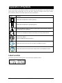
Explanation of Symbols
Some of the symbols on the USBCam2 identify it as having met the requirements for sale within the United
States and for export internationally. The "CE" and "ETL" symbols are examples of these types of marks.
The remaining symbols provide either technical or directive information.
Symbol
Description
Indicates that the USBCam2 is Class II equipment.
Indicates that the USBCam2 is Type BF equipment.
Indicates an attention to users to consult accompanying documents (this User Guide) for
more information on the USBCam2.
Conforms to EC 93/42/EEC (European Communities) concerning medical devices.
Conforms to UL 60601-1
Certified to CAN/CSA STD C22.2 NO 601.1.
Indicates the location of the Power On / Off button the USBCam2 camera.
Indicates the location of the Freeze Frame Capture button on the USBCam2 camera.
Label Location
The Schick logo and the following label can be found on the USBCam2 camera.
USBCam2 User Guide
B1051061 Rev. –
v
Waste Electrical and Electronic Equipment
Background
The European Union’s Waste Electrical and Electronic Equipment (WEEE) Directive
(2002/96/EC) has been implemented in member states as of August 13, 2005. This
directive, which seeks to reduce the waste of electrical and electronic equipment through
re-use, recycling, and recovery, imposes several requirements on producers. Schick
Technologies and its Dealers are committed to complying with the Directive.
WEEE Marking
All Schick products subject to the WEEE Directive and shipped after August 13, 2005 will
be compliant with the WEEE marking requirements. These products will be identified with
the “crossed-out wheeled bin” WEEE symbol shown below, as defined in European
Standard EN 50419, and in accordance with WEEE Directive 2002/96/EC.
This “crossed-out wheeled bin” symbol on the product or on its packaging
indicates that this product must not be disposed of with other unsorted municipal
waste. Instead, it is user’s responsibility to dispose of EE waste equipment by
handing it over to a designated collection point for the reuse or recycling of waste
electrical and electronic equipment. The separate collection and reuse or recycling
of Electrical & Electronic waste equipment will help to conserve natural resources
and ensure that it is recycled in a manner that protects the environment and human
health. For more information about where you can drop off your waste equipment
for recycling, please contact your local officials.
Reporting
According to the WEEE Directive, Schick Technologies or its Dealers will ensure that
information needed to calculate the financial obligations with respect to EEE products will
be provided as required.
WEEE from Users other than Private Households
According to the WEEE Directive, Schick Technologies or its Dealers will fulfill its
obligations for the management of WEEE from users other than private households.
Furthermore, as required by the WEEE Directive, in order to enable the date upon which
the equipment was put on the market to be determined unequivocally, a mark on the
equipment will be placed to specify that the equipment was put on the market after August
13, 2005.
vi
B1051061 Rev. –
USBCam2 User Guide
Information for Reuse Centers, Treatment and Recycling Facilities
After August 13, 2005, and as required by the WEEE Directive, Schick Technologies or its
Dealers will provide reuse, treatment, and recycling information for each type of new EEE
put on the market within one year of the date in which the equipment is put on the market.
Information will include the different EEE components and materials as well as the
location of substances in these items. The information will be provided as a printed
document or in electronic media (on CD-ROM or by web download, for example)
USBCam2 User Guide
B1051061 Rev. –
vii
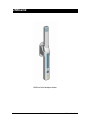
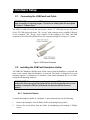
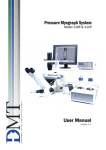
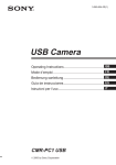
USBCam2
USBCam2 with Handpiece Holder
viii
B1051061 Rev. –
USBCam2 User Guide
1. Introduction to USBCam2
1.1. Purpose
USBCam2 (Schick P/N B6305100) is the newest hand-held intraoral camera from Schick
Technologies. An effective communication tool, USBCam2 supports streaming video and
still frame capture to help dental professionals demonstrate the current condition and posttreatment outcomes of their patients’ dental health. Video frames can be archived with
dental exams as permanent records and retrieved for comparison or subsequent review.
Ergonomic, the USBCam2 provides slim, smooth contours and a small head profile for
comfortable use and operation. Taking images with the USBCam2 integrated capture
button makes video frame capture a simple one-pushbutton step. Bright, built-in LEDs
supply superior illumination and advanced optics provide excellent depth of field for
optimal performance.
Adding USBCam2 to your office provides the following advantages:
•
Digital output over high-speed USB 2.0
•
Full motion video, full color depth, and VGA resolution quality with no
compression artifacts
•
Plugs directly into your computer, no separate power supply required, and
ports quickly from operatory to operatory — just disconnect and reconnect
•
Uses Microsoft Windows ® DirectX ® drivers — no special "framegrabbing" video card
1.2. Indications for Use
USBCam2 is to be used as an intraoral video source and is indicated for individuals who
may benefit from the addition of video images in intraoral dental examinations.
1.3. System Description
The USBCam2 system hardware consists of the following components: USBCam2
Handpiece and Holder, USB 2.0 Cable, and Camera Sheaths. The USBCam2 is connected
by USB 2.0 type A-B cable to a compatible PC workstation (running Windows XP or
Windows 2000), which also provides the power source for the device. To turn on the
USBCam2, press the Power button located near the base of the handpiece, close to the
USB connector; pressing the button a second time turns the USBCam2 off (Figure 1).
The holder for the USBCam2 serves as storage for the device when not in use and can be
installed in a variety of chair-side or adjacent surface options, providing quick access as
well as protection from accidental damage. The holder also turns off the camera
automatically when the handpiece is stored. When the handpiece is removed, the camera is
turned on automatically and is ready for use.
USBCam2 User Guide
B1051061 Rev. –
1
A programmable button to Freeze / Take / Unfreeze video is located at the side opposite
from the camera LEDs, near the middle of the handpiece (Figure 1). Built-in support for
these video functions is provided by compatible software programs such as CDR DICOM
for Windows 3.5 and higher, EagleSoft 12.0 and higher, and Patterson Imaging 12.0 and
higher. For other custom applications, a programmer’s guide is available.
Optically clear sheaths are required for each new patient and provide an effective measure
for ensuring proper hygiene and protection against infectious disease. Cleaning and
disinfection information for the USBCam2 handpiece and the holder can be found in
Section 5, Protective Measures, which includes a list of recommended products and
procedures.
1.4. Getting the Best Images with USBCam2
Getting the best results from your USBCam2 begins with having a computer system
suitable for displaying and capturing video images. For optimum performance we
recommend: (a) PCs equipped with Pentium IV processors, (b) available USB 2.0 port, (c)
minimum 8MB video memory, and (d) display values for your monitor set at least to 800
x 600 x 24-bit color. We also recommend using the factory defaults for the USBCam2. 1
IMPORTANT! USB bandwidth is shared among all USB devices. Achieving optimum
performance with the USBCam2 (30 frames-per-second video streams) may not be
possible if other USB devices are in use at the same time.
1
2
The amount of video memory on your system can be checked by running dxdiag.exe and checking the
Display tab. Color resolution can be checked by clicking Windows Start > Settings > Control Panel,
double-clicking on Display, and then clicking on the Settings tab. Factory settings for the USBCam2 are:
30 frames-per-second frame rate, fixed white balance, and auto exposure. More information about video
settings can be found in Sections B-1 and B-2.
B1051061 Rev. –
USBCam2 User Guide
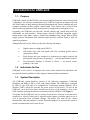
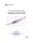
1.5. Controls on the USBCam2
An illustration of the USBCam2 is shown below in Figure 1. For a description of user
controls on the camera, refer to Table 1.
(1) Camera Lens and
Light Source (LEDs)
(3) Freeze Frame
Capture Button
(2) On / Off Button
(4) USB Connector
Figure 1. USBCam2 Controls
Table 1. Description of Camera Controls
Number
1
Description
Camera lens and LED (light-emitting diode) source
2
Power on/off button (See Note A)
3
Freeze frame capture button (See Note B)
4
USB cable connection (See Note C)
NOTE A: Light source will automatically time out after 5 minutes of continuous operation.
NOTE B: Can be set to either Freeze / Unfreeze images or Freeze / Take images. Refer to Section 4,
Operation, for details.
NOTE C: "B" connector end of USB cable connects here.
USBCam2 User Guide
B1051061 Rev. –
3
2. Hardware Setup
2.1. Connecting the USBCam2 and Cable
IMPORTANT! Do not connect the USBCam2 and cable to your computer until after you
have successfully run the setup program. Procedures for installing these files are supplied
in Section 3, "Software Setup."
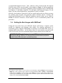
The USB 2.0 cable used with the camera has a Series "A" USB plug on one side and a
Series "B" USB plug on the other. The "A-type" plug connects to any available USB port
on the computer. The "B-type" plug connects to the handpiece. For EMC and EMI
compliance, the USB cable should not exceed a maximum length of 5 meters (5.5 yards).
Figure 2. USB Cable Connectors
2.2. Installing the USBCam2 Handpiece Holder
The USBCam2 Handpiece Holder turns off the camera when the handpiece is inserted and
turns on the camera when the handpiece is removed. The holder is designed for several
mounting options: (1) Mounted to a standard ½-inch dental instrument bar, or (2) Wallmounted with fastening hardware.
PLEASE NOTE: When selecting the mounting option for your USBCam2, choose a
location that offers easy access during patient exams and safe storage afterwards. In most
practices, mounting the USBCam2 to the dental unit will provide the best all-around
solution.
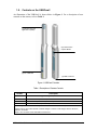
2.2.1. Dental Unit Option
To install the handpiece holder to a standard ½-inch instrument bar, do the following:
1.
Remove the handpiece from its holder before performing this procedure.
2.
Remove the cutout block from the holder by untightening and retaining 2 Phillips
screws.
4
B1051061 Rev. –
USBCam2 User Guide
3.
Attach the holder to the instrument rail mounting block by tightening 2 Phillips
screws removed previously.
4.
Position the holder on the instrument bar of your dental unit, using the cutout space
on the back of the mounting block as a guide.
5.
When the holder is in position, use an Allen key to tighten 2 set screws located at the
bottom of the mounting block.
Figure 3. Handpiece Holder Instrument Rail Installation
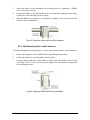
2.2.2. Wall-Mounting Option (with Fasteners)
To install the handpiece by fastening it to a wall or other vertical surface, do the following:
1.
Remove the handpiece from its holder before performing this procedure.
2.
Position the holder on a smooth stable vertical surface.
3.
Using the holes on the back of the holder as guides, fasten the holder securely to the
wall using 2 (#6 x 3/4) dry wall screws (not supplied) or other hardware appropriate
to the mounting surface.
Figure 4. Handpiece Holder Wall Mounting Installation
USBCam2 User Guide
B1051061 Rev. –
5
3. Software Setup
3.1. What You Will Need to Complete this Section
To expedite software installation, please have the following items available:
•
USBCam2 Driver CD
•
USBCam2
•
USB 2.0 type A-B Cable (not supplied, but should not exceed a maximum
length of 5 meters (5.5 yards) to comply with EMC and EMI standards)
3.2. Before You Start Installing Software
IMPORTANT! CDR users please do not connect the USBCam2 and cable to your
computer until after you have installed the device driver and updated the DirectX files on
your system. Procedures for installing these files can be found in this section.
The software for your USBCam2 consists of the following components:
•
USBCam2 Device Driver Installation
•
DirectX Update
You must install each of these components successfully to ensure proper operation of your
USBCam2. Actual installation differs slightly between operating systems (Windows 2000
and Windows XP), so you should follow the procedures that refer to your particular
system. (Procedures can be found in this section.) If you're not sure which operating
system is installed on your computer, right click on the My Computer icon on your
desktop and select Properties.
To review USBCam2 system requirements, refer to Section 1.4, Getting the Best Images
with USBCam2.
6
B1051061 Rev. –
USBCam2 User Guide
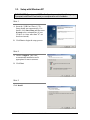
3.3. Setup with Windows XP
PLEASE NOTE: Do not connect USBCam2 until you have completed the following steps.
If prompted, install DirectX 9 and restart your computer at the end of installation.
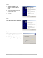
STEP 1
A. Insert the “USBCam2 Driver” CD.
Setup should start automatically. If it
doesn't, click Start, Run, and then enter
d:\setup at the command line (if your
CD drive is a letter other than "d", use
that letter instead).
B. Click Next to begin the setup process.
STEP 2
A. Choose Complete. This is the
recommended installation and is
appropriate for most customers.
B. Click Next.
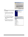
STEP 3
Click Install.
USBCam2 User Guide
B1051061 Rev. –
7
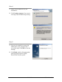
STEP 4
A. Setup will pre-install files to your
workstation.
B. Click Continue Anyway if you receive
a message about Windows logo testing.
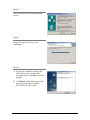
STEP 5
A. You may be reminded to connect the
USBCam2 to your computer after a
successful setup. Click OK to close the
message.
B. Click Finish, which will automatically
start the setup program to update
DirectX files on your system.
8
B1051061 Rev. –
USBCam2 User Guide
STEP 6
A. Connect the USBCam2 to your
computer if you haven’t done so
already.
B. Click No at the option to connect to
Windows Update service.
C. Click Next.
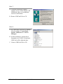
STEP 7
Click Next to install software automatically.
STEP 8
A. Setup will copy the drivers to your
workstation.
B. Click Continue Anyway if you receive
a message about Windows logo testing.
USBCam2 User Guide
B1051061 Rev. –
9
STEP 9
A. Click Finish.
B. The message, “Your new hardware is
installed and ready to use” will appear
momentarily in the Windows System
tray.
C. Remove USBCam2 Driver CD.
D. As a final check, open Device Manager
(Windows Start > Control Panel >
System > Hardware tab > Device
Manager).
E. In Device Manager, open the list of
Imaging devices. Schick Technologies
USBCam2 will be displayed there.
10
B1051061 Rev. –
USBCam2 User Guide
3.4. Setup with Windows 2000
PLEASE NOTE: Do not connect USBCam2 until you have completed the following steps.
If prompted, install DirectX 9 and restart your computer at the end of installation.
STEP 1
A. Insert the “USBCam2 Driver” CD.
Setup should start automatically. If it
doesn't, click Start, Run, and then enter
d:\setup at the command line (if your
CD drive is a letter other than "d", use
that letter instead).
B. Click Next to begin the setup process.
STEP 2
A. Choose Complete. This is the
recommended installation and is
appropriate for most customers.
B. Click Next.
STEP 3
Click Install.
USBCam2 User Guide
B1051061 Rev. –
11
STEP 4
Click Yes at Microsoft’s digital signature
screen.
STEP 5
Setup will copy the drivers to your
workstation.
STEP 6
A. You may be reminded to connect the
USBCam2 to your computer after a
successful setup. Click OK to close the
message.
B. Click Finish, which will automatically
start the setup program to update
DirectX files on your system.
12
B1051061 Rev. –
USBCam2 User Guide
STEP 7
A. Click Yes at Microsoft’s digital
signature screen. Unlike Windows XP
installations, there are no additional
screens or notifications.
B. Remove USBCam2 Driver CD.
STEP 8
A. As a final check, open Device Manager
(Windows Start > Control Panel >
System > Hardware tab > Device
Manager).
B. In Device Manager, open the list of
Imaging devices. Schick Technologies
USBCam2 will be displayed there.
C. .Remove USBCam2 Driver CD.
USBCam2 User Guide
B1051061 Rev. –
13
4. Operation
4.1. Operating the Camera
Refer to the following sections for instructions on turning the USBCam2 on and off and
taking still images from streaming live video ("freeze-frame" capture).
4.1.1. Turning the Camera On
Before turning on the camera make sure the cable connections are secured. Turn on the
camera by clicking the Power On/Off button (Figure 1, item 2). Removing the handpiece
from its holder also turns the camera on.
4.1.2. Turning the Camera Off
When the camera's light is on, clicking the camera’s Power On/Off button (Figure 1, item
2) shuts power off to the camera. Clicking the Power On/Off button restores power to
camera and turns the LEDs back on.
When not in use, store the camera in its holder to protect the device and for easy access.
Placing the camera in its holder turns off the camera automatically.
NOTE: Camera will turn off automatically after 5 minutes of continuous use.
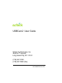
4.1.3. Pausing and Capturing Still Frame Images
NOTE: The following steps apply to the use of USBCam2 with CDR DICOM software.
To set up your handpiece Freeze Frame button for Freeze/Take mode, do the following:
•
Click the Setup button on the Video Capture window
•
Select the option for Freeze/Take
•
Click OK to save settings
To use your handpiece in this mode, depress the Freeze Frame button once (Figure 1, item
3) to capture the frame. To resume live video after taking an image, select any empty
viewbox and click on it.
14
B1051061 Rev. –
USBCam2 User Guide
4.1.4. Pausing and Resuming Live Video
NOTE: The following steps apply to the use of USBCam2 with CDR DICOM software.
To set up your handpiece Freeze Frame button for Freeze/Unfreeze mode, do the
following:
•
Click the Setup button on the Video Capture window
•
Select option for Freeze/Unfreeze
•
Click OK to save settings
To use your handpiece in this mode, depress the Freeze Frame button once (Figure 1, item
2) to pause live video. Depressing the button again will resume streaming video.
To capture an image when live video is paused, click the Take button on the Video Capture
window.
Figure 5. Video Window Setup and Capture Buttons
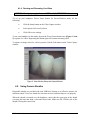
4.2. Using Camera Sheaths
Disposable sheaths are provided with each USBCam2 System as an effective measure for
infection control. Use a new sheath for each intra-oral use, and then dispose it of properly.
When the sheath is inserted over the handpiece, notice that the upper part of the sheath
(covering the lens) has both a clear and frosted side. Make sure the CLEAR side of the
sheath is facing the camera lens.
USBCam2 User Guide
B1051061 Rev. –
15
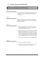
4.3. Using the Camera with CDR DICOM
NOTE: Refer to the CDR DICOM User Guide, Schick P/N 1051047, for detailed
information on the use and operation of CDR DICOM software.
STEP 1
Start CDR DICOM from the Windows Start button or by
clicking the shortcut to CDR DICOM for Windows on
your desktop.
STEP 2
When the CDR exam window appears, click on New
Exam under the File menu or just click the New Exam
button on the toolbar.
STEP 3
A. Enter the appropriate patient information and then
click on Video Series. You may use a pre-defined
video series or create a new one.
B. If you choose to create a new video series, click Edit
Series, which opens the New Custom Video Series
dialog box. The numbers in the text boxes correspond
to how many target frames are included in this series.
You can edit the numbers in the text boxes, creating a
series customized with the views you wish to include.
C. Enter a name for this video series. Click OK to finish.
STEP 4
A. Place a new sheath over the camera.
B. Click the Power button on the handpiece to turn the
camera LEDs on if they are not on already.
16
B1051061 Rev. –
USBCam2 User Guide
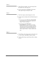
STEP 5
A. In the CDR exam window, click on an empty frame
that matches the video image area.
B. Once the target frame is highlighted, click on the
frame again to begin viewing live video.
STEP 6
A. The Video Capture window displays live video.
B. Position camera to display the desired dental image on
screen.
1) If you set up your USBCam2 for Freeze/Take,
pressing the Freeze Frame button captures the
image. Continue with Step 7.
2) If you set up your USBCam2 for
Freeze/Unfreeze, pressing the Freeze Frame
button pauses live video. To resume streaming
video, press the Freeze Frame button again. To
capture an image, click the Take button on the
Video Capture window. Continue with the next
step.
STEP 7
A. The still frame video image appears in either the exam
or zoom window, depending on capture settings.
B. To take another image, repeat this procedure, starting
at Step 5.
USBCam2 User Guide
B1051061 Rev. –
17
4.4. Acquiring Video Images with the Footpedal
Serial footpedals (Schick P/N B2501100; PDCO P/N 07-0410100) can be used to control
the capture of video images. Refer to the following table for information on using this
footpedal to capture video images.
Table 2. Footpedal Actions
Video
Streaming
Still
Desired Action
Freeze Image
Close Video Window
(Image is frozen in video window)
(Image is frozen in video window)
Use Pedal
Take Image
Unfreeze Image
Green
Amber
Green
Amber
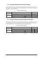
4.5. Acquiring Video Images with Keyboard Shortcuts
Video image acquisition can be also accomplished though the use of shortcut keys. To use
the following shortcuts, press and hold down the first key (always the Alt key) and then
press the second key (shown after the plus sign) for the appropriate action.
Table 3. Keyboard Shortcuts
Video
Streaming
Still
18
Desired Action
Freeze Image
Close Video Window
(Image is frozen in video window)
(Image is frozen in video window)
B1051061 Rev. –
Use Keys
Take Image
Unfreeze Image
Alt
Alt
Alt
Alt
F
C
T
U
USBCam2 User Guide
5. Protective Measures
5.1. Sheaths
The USBCam2 system uses disposable sheaths (Schick P/N 6310120) to ensure proper
infection control. Sheaths are intended for single-use only. Do not use the camera for
intraoral use until a new sheath has been properly fitted to the handpiece. After each intraoral use, remove the sheath and dispose of it properly. Then, clean the outer surfaces of the
camera using mild cleaning solution (mild soap and water) and sterile wipes. A new sheath
must be used for each patient.
Disposable sheaths are provided with every USBCam2 system. In the U.S., additional
sheaths can be ordered from Patterson Dental Supply, Inc. by calling 1-800-328-5536.
International customers should contact the authorized international dealer for Schick
Technologies products in their country or region.
5.2. Handpiece and Lens
IMPORTANT! Be sure to disconnect the camera from its USB cable and port before
performing any cleaning procedures. Before cleaning the lens, be certain that it is free of
any abrasive contaminants. This will help to avoid the formation of scratches while cleaning.
To disinfect the handpiece, use a 70% Ethanol solution, administered by saturating spray
or moist towelettes. Do not soak the handpiece and be sure to dry it completely.
To clean the handpiece, use a clean lint-free cloth and any of the following solutions. Do
not soak the handpiece and be sure to dry it completely.
•
Mild soap and water
•
Isopropyl alcohol (70%)
•
Isopropanol (>15%) / quaternary ammonium compounds combination
(<1%)
To clean the lens surface, moisten a soft cotton swab dipped in rubbing (isopropyl)
alcohol. Gently wipe the lens surface end-to-end in straight lines without applying
pressure; do not scrub. Allow the alcohol to evaporate from the lens surface. Repeat these
steps, as needed, until the lens surface is clean.
5.3. Computer
To avoid cross contamination, follow the cleaning instructions provided by your computer
manufacturer and implement them as part of your normal routine for ensuring proper
sterilization and disinfectant of tools in your dental practice.
USBCam2 User Guide
B1051061 Rev. –
19
Appendix A. Reference Information
A-1. Removal and Replacement Procedures
There are no user-serviceable parts in the USBCam2 system. Should you experience
problems with the USBCam2, please contact your local distributor of Schick Technologies
products. In the United States, Schick Technologies products are available exclusively
through Patterson Dental Supply, Inc. Call your local Patterson representative, local
Patterson branch, or 1-800-873-7683 for more information.
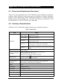
A-2. Summary of Specifications
USBCam2 is ETL-certified and compliant with the safety standards listed below.
Table 4. Specifications
Item
EMC/Safety
CAN/CSA C22.2
No.601.1-M90
Medical Electrical Equipment Part 1: General
Requirements for Safety
EC 93/42/EEC
Medical Device Directive
IEC60601-1
Medical Electrical Equipment Part 1: General
Requirements for Safety
IEC60601-1-2
Medical Electrical Equipment Part 1: General
Requirements for Safety 2.Collateral Standard:
Electromagnetic Compatibility – Requirements and Tests
UL60601-1
Medical Electrical Equipment: General Requirements for
Safety
Input electrical rating
5VDC @ 440mA
Transport and storage
conditions
Ambient temperature range: 0° F (-18° C) to 150° F (66° C)
Relative humidity range: less than 75%
Atmospheric pressure range: 700 hPa to 1060 hPa
Equipment type
20
Value
Type BF equipment
(on handpiece)
Fuse
63VDC/VAC, 1A fast blow fuse
Restricted service
statement
Unless otherwise specified, this unit should be serviced only by the
manufacturer. It contains no user-serviceable parts.
Imager
CCD
Video output
High Speed USB 2.0
Focus range
5 - 45 mm (0.2 - 1.77 in)
Focus type
Fixed
External power supply
None (power supplied via USB)
Maximum cable length
5 m (5.5 yds)
B1051061 Rev. –
USBCam2 User Guide
Item
Value
Handpiece weight
42.5 g (1.5 oz)
Special features
Integrated frame capture button
A-3. Leakage Current Statement
USBCam2 complies with the leakage current requirements of IEC 60601-1-1 safety
standard. Variations, however, may exist in the construction of computers to which the
USBCam2 is connected. Users are advised to have a qualified electrician perform a
leakage test on their equipment before using the USBCam2.
USBCam2 User Guide
B1051061 Rev. –
21
A-4. EMC Tables
The following tables provide USBCam2 compliance information to electromagnetic
compatibility (EMC) and electromagnetic immunity (EMI) standards. To ensure
conformance, the customer or user must use the USBCam2 in environments that are
consistent with these standards.
The USB cable required with the USBCam2 camera must also comply with the same
standards. To meet those specifications, the USB A-B type cable should not exceed a
maximum length of 5 meters (5.5 yards). Cables longer than that distance may result in
increased emissions or decreased immunity.
Table 5. Guidance and Manufacturer's Declaration - Electromagnetic Emissions
PLEASE NOTE: The USBCam2 is intended for use in the electromagnetic environment specified
below. The customer or user of the USBCam2 must ensure that it is used in such an environment.
Emissions Test
RF emissions
Compliance
Guidance
The USBCam2 uses RF energy only for its internal function.
Therefore, its RF emissions are very low and are not likely to
cause any interference in nearby electronic equipment.
Group 1
CISPR 11
RF emissions
Class B
CISPR 11
Harmonic emissions
The USBCam2 is suitable for use in all establishments
including domestic establishments and those directly
connected to the public low-voltage supply network that
supplies buildings used for domestic purposes.
Class D
IEC 61000-3-2
Voltage fluctuations/
flicker emissions
Complies
IEC 61000-3-3
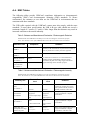
Table 6. Guidance and Manufacturer's Declaration - Electromagnetic Immunity
PLEASE NOTE: The USBCam2 is intended for use in the electromagnetic environment specified
below. The customer or user of the USBCam2 must ensure that it is used in such an environment.
Immunity Test
IEC 60601 Test
Level
Compliance
Level
Electrostatic discharge
(ESD)
±6 kV contact
±6 kV contact
IEC 61000-4-2
±8 kV air
±8 kV air
Electrical fast
transient/burst
±2 kV for power
supply lines
±2 kV for power
supply lines
IEC 610004-4
±1 kV for input/output
lines
±1 kV for
input/output lines
Surge
± 1 kV differential
mode
± 1 kV differential
mode
± 2kV common mode
± 2kV common
mode
< 5% UT
< 5% UT
(>95% dip in UT)
(>95% dip in UT)
IEC 61000-4-5
Voltage dips, short
interruptions and voltage
variations on power
22
B1051061 Rev. –
Guidance
Floors should be wood, concrete or
ceramic tile. If floors are covered
with synthetic material, the relative
humidity should be at least 30%.
Mains power quality should be that of
a typical commercial or hospital
environment.
Mains power quality should be that of
a typical commercial or hospital
environment.
Mains power quality should be that of
a typical commercial or hospital
environment. If the user of the
USBCam2 User Guide
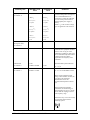
Immunity Test
supply input lines
IEC 60601 Test
Level
Compliance
Level
for 0.5 cycle
for 0.5 cycle
< 40% UT
< 40% UT
(>60% dip in UT)
(>60% dip in UT)
for 5 cycles
for 5 cycles
USBCam2 requires continued
operation during mains interruptions,
it is recommended that the PC
workstation to which the USBCam2
is connected be powered from an
uninterruptible power supply or
battery.
< 70% UT
< 70% UT
NOTE: UT is the AC mains voltage
prior to application of the test level.
(>30% dip in UT)
(>30% dip in UT)
for 25 cycles
for 25 cycles
IEC 61000-4-11
Power frequency (50/60
Hz) magnetic field
Guidance
< 5% UT
< 5% UT
(>95% dip in UT)
(>95% dip in UT)
for 5 sec
for 5 sec
3A/m
3A/m
IEC 61000-4-8
Portable and mobile RF
communication equipment should be
used no closer to any part of the
USBCam2, including its cables, than
the recommended separation distance
calculated from the equation
applicable to the frequency of the
transmitter.
Conducted RF
3 Vrms
IEC 61000-4-6
150 kHz to 80 MHz
3 Vrms
d= 1.2 √ P
Radiated RF
3 V/m
3 V/m
d= 1.2 √ P for 80 MHz to 800Mhz
IEC 61000-4-3
80 MHz to 2.5 GHz
Recommended separation distance:
d= 2.3 √ P for 800 MHz to 2.5Ghz
Where P is the maximum output
rating of the transmitter in watts (W)
according to the transmitter
manufacturer and d is the
recommended separation in meters
(m).
Field strengths from fixed RF
transmitters, as determined by an
electromagnetic site survey,a should
be less than the compliance level in
each frequency range. b
Interference may occur in the vicinity
of equipment marked with the
following symbol.
USBCam2 User Guide
B1051061 Rev. –
23
Immunity Test
IEC 60601 Test
Level
Compliance
Level
Guidance
NOTE 1: At 80 MHz and 800 MHz, the higher frequency range applies.
NOTE 2: These guidelines may not apply in all situations. Electromagnetic propagation is affected by absorption
and reflection from structures, objects and people
a
Field strengths from fixed transmitters, such as base stations for radio (cellular/cordless) telephones and land
mobile radios, amateur radio, AM and FM radio broadcast and TV broadcast cannot be predicted theoretically with
accuracy. To assess the electromagnetic environment due to fixed RF transmitters, an electromagnetic site survey
should be considered. If the measured field strength in the location in which the USBCam2 is used exceeds the
applicable RF compliance above, the USBCam2 should be observed to verify normal operation. If abnormal
performance is observed, additional measures may be necessary, such as reorienting or relocating the USBCam2.
b
Over the frequency range 150 kHz to 80 MHz, field strengths should be less than 3 V/m
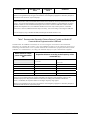
Table 7. Recommended Separation Distance Between Portable and Mobile RF
Communications Equipment and the USBCam2
PLEASE NOTE: The USBCam2 is intended for use in an electromagnetic environment in which radiated RF
disturbances are controlled. The customer or user of the USBCam2 can help prevent electromagnetic interference by
maintaining a minimum distance between portable and mobile RF communications equipment (transmitters) and the
USBCam2 as recommended below, according to the maximum output power of the communications equipment.
Rated maximum output
power of the transmitter
(W)
Separation distance according to the frequency of the
transmitter (m)
150 kHz to 800 MHz
800 MHz to 2.5 GHz
d=1.2 x √P
d= 2.3 x √P
0.01
0.12
0.23
0.1
0.38
0.73
1
1.2
2.30
10
3.8
7.3
100
12.0
23.00
For transmitters rated at a maximum output power not listed above, the recommended separation distance d in
meters (m) can be estimated using the equation applicable to the frequency of the transmitter, where P is the
maximum output power rating of the transmitter in watts (W) according to the transmitter manufacturer.
NOTE 1: At 800 MHz, the separation distance for the higher frequency range applies.
NOTE 2: These guidelines may not apply in all situations. Electromagnetic propagation is affected by absorption
and reflection from structures, objects, and people.
24
B1051061 Rev. –
USBCam2 User Guide
Appendix B. Additional Information
B-1. Checking DirectX Version and Video Information
When installing your USBCam2, you will be prompted to install the latest version of
Microsoft's DirectX files on your system (DirectX 9). We strongly recommend that you
install these files as earlier versions of DirectX prior to DirectX 8.1 are not compatible
with USBCam2. In the event you experience video problems with USBCam2, please
verify that your system has properly installed DirectX version 8.1 or later by performing
the steps below.
Video quality and performance is also affected by the amount of video memory available.
By running dxdiag.exe, as documented below, and checking the Display tab, you can
verify the amount of video memory available on your graphics card.
STEP 1
A. At the Windows desktop, click Start, Run, and then
type dxdiag.exe.
B. The "DirectX Diagnostic Tool" dialog box is
displayed.
C. Under the System tab, verify that your current DirectX
version is 8.1 or higher.
STEP 2
A. If your DirectX version is 8.1 or higher, you have the
correct version for USBCam2 operation. Click Exit to
close this dialog box.
B. If your DirectX version is less than 8.1, repeat the
installation steps found in the “Software Setup”
section of this manual.
USBCam2 User Guide
B1051061 Rev. –
25
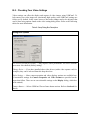
B-2. Checking Your Video Settings
Video settings can affect the display and capture of video images using USBCam2. To
help ensure your video images are consistently high quality, some USBCam2 settings are
factory set by default. In the event, however, that some settings need to be adjusted, that
can be done using options found on the video setting dialog boxes. Refer to the following
tables for more information.
Table 8. Setup Dialog Box Description
Dialog Box Options
Use Preview Stream for Display — May improve video performance for slower Pentium
processors. Not checked (factory setting).
Change Driver — If you have installed other video drivers (with a video capture card, for
example), they can be selected from this drop-down box.
Video Settings — More camera operation and video displays options are available here
(Customizable settings for Camera Properties and Video Format are provided on the
pages that follow. There are no user-selectable settings on the Display dialog, which has
been omitted.)
Camera Button — Selects USBCam2 Freeze-frame button actions. Refer to Section 4 for
details.
26
B1051061 Rev. –
USBCam2 User Guide
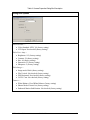
Table 9. Camera Properties Dialog Box Description
Dialog Box Options
Video Decoder —
• Video Standard: NTSC_M (factory setting)
• VCR Input: Not checked (factory setting)
Video Proc. Amp —
•
•
•
•
•
Brightness: 112 (factory setting)
Contrast: 38 (factory setting)
Hue: 64 (factory setting)
Saturation: 25 (factory setting)
Sharpness: 2 (factory setting)
Video Image —
•
•
•
•
Image mask: Black (factory setting)
Flip Vertical: Not checked (factory setting)
Flip Horizontal: Not checked (factory setting)
Use PC Cam: Not checked (factory setting)
Camera —
• White Balance: Fixed White Balance (factory setting)
• Shutter Mode: Electric Iris (factory setting)
• Enhanced Motion Stabilization: Not checked (factory setting)
USBCam2 User Guide
B1051061 Rev. –
27
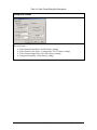
Table 10. Video Format Dialog Box Descriptions
Dialog Box Options
Stream Format —
•
•
•
•
28
Video Format Frame Rate: 30.000 (factory setting)
Video Format Color Space / Compression: YUY2 (factory setting)
Video Format Output Size: 640 x 480 (factory setting)
Compression Quality: 1.000 (factory setting)
B1051061 Rev. –
USBCam2 User Guide
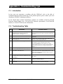
Appendix C. Troubleshooting Tips
C-1. Introduction
In the event you experience a problem with the USBCam2, refer to the table of
troubleshooting tips found on this page. If the problem persists, please contact your local
distributor of Schick Technologies products.
In the United States, Schick Technologies products are available exclusively through
Patterson Dental Supply, Inc. Call your local Patterson representative, local Patterson
branch, or 1-800-873-7683 for more information.
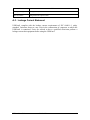
C-2. Troubleshooting Table
Item
Description
Corrective Action
1
Camera LEDs illuminate and remain on
immediately after connecting USB cable,
whether software is running or not.
This is normal camera operation. To turn off LEDs, press
the Power button on the camera, or place the camera in its
handpiece.
2
Camera turns on and off intermittently.
Check USB cable connection at camera and at PC
connectors.
3
Cannot select 640 x 480 output size in Video
Format dialog box.
Camera is not connected to High-Speed USB 2.0 port.
Reconnect camera to appropriate port.
4
Spots are visible on video image.
Check camera lens for spots and follow the instructions in
the Handpiece and Lens cleaning section of this
document (Section 5.2). Also check the “fit” of the
camera sheath over the lens. Camera sheath should be on
tight enough so there are no wrinkles across the lens
section.
5
Extraoral images appear grainy or blurry.
Camera is strictly intended for intraoral use.
6
Camera options are missing from the
DirectShow Video dialog box.
Camera driver was not installed correctly. Disconnect
camera from USB cable, uninstall USBCam2 driver, and
follow the instructions in the Software Setup section of
this document (Section 3).
7
Corrupted video image is displayed when using
the camera with an Ultra Port USB 2.0 PCI card,
ALI chipset.
Replace the USB card with one that is compatible with
the camera.
8
Momentary blip occurs recurrently during video
exam.
Change to a different USB port.
9
Image appears nearly completely red during
video exam.
Toggle between the Fixed Balance / Auto White Balance
options in the Camera properties dialog box.
USBCam2 User Guide
B1051061 Rev. –
29
Index
A
S
Acquiring Video Images with Footpedal, 15
Acquiring Video Images with Shortcuts, 15
Safety Issues
Avoid Excessive Temperatures, iii
Check USBCam2 before Using, iii
Ensure USBCam2 Operates Optimally, iv
Items Not Part of the System, iii
Operate the USBCam2 as Directed, iii
Proper PC Workstation Cleaning Methods, iv
Proper System and PC Workstation Installation and
Operation, iv
Recommended Procedures, iii
RF Interference Considerations, iii
C
Cable Connection, 4
Checking DirectX and Video Information, 22
Checking Video Settings, 23
Computer Protective Measures, 16
Controls on USBCam2, 3
Sheaths, 16
Software Setup, 6
Summary of Specifications, 17
E
EMC Tables, 19
Ensure USBCam2 Operates Optimally, iv
Explanation of Symbols, v
T
Troubleshooting
Introduction to, 26
List of Steps for, 26
F
Footpedal, 15
U
H
USBCam2
Handpiece and Lens Protective Measures, 16
Handpiece Installation
Dental Chair Mounting, 4
Wall Mounting, 5
Hardware Setup, 4
L
Leakage Current Statement, 18
O
Operate USBCam2 as Directed, iii
Operating the USBCam2, 11
P
Pausing and Capturing Still Frame Images, 11
Pausing and Resuming Live Frame Images, 12
Proper PC Workstation Cleaning Methods, iv
Proper System and PC Workstation Installation
and Operation, iv
Protective Measures, 16
Avoid Excessive Temperatures when Using, iii
Check before Using, iii
Connecting the Cable, 4
Controls on, 3
Description of, 1
Electromagnetic Emissions, 19
Electromagnetic Immunity, 19
Getting the Best Images with, 2
Handpiece and Lens Protective Measures, 16
Handpiece Holder Installation, 4
Hardware Setup, 4
Operation, 11
Pausing and Capturing Still Frame Images, 11
Pausing and Resuming Live Images, 12
Picture of, viii
Protective Measures, 16
Recommended Separation Distance Between
Portable and Mobile RF Equipment, 21
Sheaths, 16
Software Setup, 6
Troubleshooting, 26
Turning the Camera Off, 11
Turning the Camera On, 11
Using Camera Sheaths, 12
Using the Camera with CDR DICOM, 13
R
Recommended Procedures, iii
Reference Information, 17
Removal and Replacement Procedures, 17
RF Interference, iii
30
W
Waste Electrical and Electronic Equipment (WEEE),
vi
B1051061 Rev. –
USBCam2 User Guide