1
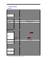
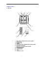
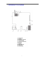
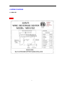
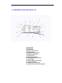
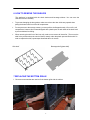
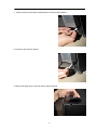
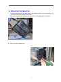
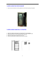
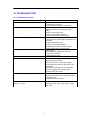
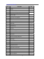
WINE CHILLER
Model Number: WBV21DZ
SERVICE MANUAL
CAUTION
Before servicing, make sure to unplug the appliance.
Replace all part before operating the appliance.
Failure to do so could result in death, electrical shock or personal injury.
Avanti Products, A Division of the mackle Co.,Inc INC.
P.O.Box 520604 – Miami, Florida 33152 USA
www.avantiproducts.com
TABLE OF CONTENTS
1.
SPECIFICATIONS……………………………………………………………………3
2.
NAME OF PARTS……………………………………………………………………4
3.
REFRIGERANT CYCLE DIAGRAM……………………………………………….5
4.
WIRING DIAGRAM…………………………………………………………………..6
5.
COMPRESSOR ROOM VIEW AND PARTS LIST……………………………….7
6.
HOW TO REMOVE THE SHELVES………………….……………………………8
7.
HOW TO REPLACE THE BOTTOM GRILLE……………………………….…..8-9
8.
HOW TO REMOVE THE DOOR….………………….…………………………..9-11
9.
RELACING THE CONTROL PANEL……………………………………….....11-12
10. REPLACE THE MAIN PCB………………….…………………...…………..…13-14
11. REPLACE REAR AIR DUCT THE EVAPORATOR FAN MOTOR…………15-16
12. REPLACE THE LED LIGHT ASSEMBLY…………………………..………...16-17
13. REPLACE THE CONDENSER FAN MOTOR, COMPRESSOR STARTER&
PROTECTOR........................................................................................................18-19
14. REPLACE THE DOOR GASKE, CHARCOAL FILTRATION………………....20
15.
TROUBLESHOOTING…………………………………………………………...21-22
16.
EXPLOSION VIEW & PARTS LISTS……………………………….….……...23-25
2
1.
SPECIFICATIONS
1.1 WBV21DZ
WBV21DZ
BUILT-IN OR RECESSED OR FREE STANDING
Model No.
Type
Capacity
21
75
No. of Wine Bottles
Zone One - L
Capacity
Zone Two - L
75
Zone Three - L
N.A
Performance & Features
16 ~ 38
Left side 7 ~ 18 / 45 ~ 65
Right side 1 ~ 7 / 34 ~ 43
115/60
Ambient Temp. Range °C
Setting Temp. Range
°C/°F
Power Source
V/Hz
Rated Input
W
170
Rated Current
A
2.2
Noise Level
dB(A)
Less than 45
Automatic
Defrost Type
Electronic
Cyclopentane
Temp. Control
Blowing Agent
Refrigerating System
Wind cooling
Cooling System
AE1350Y/HYE55Y42
Model No.
Compressor
Type
Hermetic
LRA
13.1
2.0
RLA
Overload Protector
B60-125
PTC Starter
QP2-22/*
/
Oil
Condenser Fan Motor
Evaporator Fan Motor
YJF610A-610-RX
Model No.
110-120V, 60Hz
Rating
PL92B12H
Model No.
12 V, 0.2A
Capillary (Ø0.6 x 1800 mm)
R134a / 90g
Rating
Expansion device
Refrigerant / Charged Volume
Dimensions & Weights
Net Dimensions
Packing Dimensions
Width - mm
Height - mm
Depth - mm
Width - mm
624
856
595
655
Height - mm
906
705
Depth - mm
Weight
51/58
Net / Gross - KGS
* Specifications are subject to change without prior notice.
3
2. Name of Parts
2.1 WBV21DZ
1
2
3
4
5
12
11
10
6
7
1.
2.
3.
4.
5.
6.
7.
8.
9.
10.
11.
12.
9
8
WINE CHILLER TEMPERATURE CONTROL PANEL
INTERIOR FAN
INTERIOR LIGHT
CABINET
BEVERAGE CENTER TEMPERATURE CONTROL PANEL
WINE BOTTLE SHELVES
WINE BOTTLE STORAGE RACK / BASKET
BEVERAGE SHELVES
STORAGE BASKET
LEVELING LEGS
LOCK
CHARCOAL FILTER
4
3. REFRIGERANT CYCLE DIAGRAM
1. Compressor
2. Hot Pipe
3. Condenser (Internal)
4. Condenser Fan
5. Condenser (External)
6. Dry Filter
7. Capillary
8. Evaporator Fan
9. Evaporator
10. Accumulator
5
4. WIRING DIAGRAM
4.1 WBV21DZ
***********
6
5. COMPRESSOR VIEW AND PARTS LIST
1. Suction Pipe
2. Compressor
3. Process Pipe
Outlet Pipe of Condenser
4. Discharge Pipe
5. Condenser Fan Supporter
6. Condenser Fan Cover
7. Condenser Fan
8. Condenser Fan Motor
9. Power Supply Cord with Plug
10. Junction Box
11. Electrical Box of Compressor
12. Compressor Base
13. Compressor Junction Box
14. Compressor Junction Box supporter
7
6. HOW TO REMOVE THE SHELVES
The appliance is equipped with the wired shelves and beverage shelves. You can move the
shelves out and in smoothly.
•
To prevent damaging the door gasket, make sure to have the door all the way opened when
pulling the bottom shelf out of the rail compartment.
•
For easy access to the storage content, you must pull the shelf approximately 1/2 out of the rail
compartment, however this unit was designed with a plastic post on each sides of the shelf track
to prevent bottles from falling.
•
When removing the shelf out of the inner rail, make sure to remove all items first. Then move the
shelf to the position where the notch of shelf is exactly under the plastic post and lift the shelf. In
order to replace the shelf, repeat steps described above in reverse.
Wire shelf
Beverage shelf (glass shelf)
7 REPLACING THE BOTTOM GRILLE
1.Remove two screws that are used to fix the bottom grille with the cabinet.
8
1. The bottom grille is shown as below.
8. HOW TO REMOVE THE DOOR
Note: All parts removed must be saved to do the reinstatement of door.
1. Remove the bottom grille according to “Replacing the Bottom Grille”.
2. Pull out and remove the lower hinge cover.
9
3. Disconnect the communication cable between the door and the cabinet.
4. Pull out the wire from the cabinet.
5. Remove the upper hinge cover from the top right of the door
10
6. Remove the three screws with the upper hinge and remove the upper hinge.
7. Lift up the door slightly and remove the wire from the lower hinge.
9.RELACING THE CONTROL PANEL
1. Remove the cover behind the control panel with a screw driver.
11
2. Remove two screws that are used to fix the PCB broad.
3. Remove PCB board and disconnect the cables.
12
10. REPLACING THE MAIN PCB.
1. Lay down the cabinet to the left side and place it on a padded surface to prevent scratching it. The
main PCB is located at the bottom of the cabinet.
Note: Never lay down the cabinet to the right side as it may damage the compressor.
2. Remove the main PCB box cover
13
3. Disconnect all terminals on the main control PCB.
4. Remove four screws that are used to fix the main control PCB. Now you can replace the main
control PCB.
14
11. REPLACING THE FAN MOTOR AND EVAPORATOR
1. Remove all the shelves according to “How to remove the shelves”.
2. Remove the screws that are used to fix the air duct with the cabinet.
2. Disconnect the wires then you can replace the evaporator fan motor.
15
4. Remove screws between air dust and the evaporator fan motor, then you can replace the fan
motor.
EVAPORATOR PICTURE
*****************
12. REPLACING THE LED LIGHT ASSEMBLY
1. Remove the top two shelves according to “How to remove the shelves”.
2. Turn the light cover counter-clockwisely to remove.
16
3. Remove the two screws that are used to fix light holder.
4. Disconnect the cables then you can replace the LED light assembly.
17
13. REPLACING THE CONDENSER FAN MOTOR, THE
COMPRESSOR PTC STARTER AND OVERLOAD PROTECTOR
1. Remove the seven screws that are used to fix the condenser fan motor with the compressor
base.
2. Remove the clamp that is used to fix the junction box of compressor. Then dismantle
the junction box cover.
18
3.Disconnect the condenser fan motor cable with compressor. Now you can replace the
condenser fan motor.
4. Disconnect the compressor PTC starter and overload protector cable with compressor. Now you
can replace the compressor PTC starter and overload protector.
***********Starter and protector pictures
19
14. REPLACING THE DOOR GASKET
1. Open the door and detach the old door gasket from the doorframe by pulling off the gasket.
15. REPLACING CHARCOAL FILTRATION
1.
2.
3.
4.
5.
Remove the bottles of wine stored on the two(2) shelves in front of the filter.
Remove the shelves and set aside to be replaced once you have changed the filter.
Hold the filter and turn it counter-clockwisely and then pull it out.
Remove the existing filter and replace with a new one.
Put the new filter into the hole and then turn the filter clockwisely.
20
16. TROUBLESHOOTING
16.1 Troubleshooting Guide
PROBLEM
Wine Chiller does not operate.
Wine Chiller is not cold enough.
Turns on and off frequently.
The light does not work.
Vibrations.
The Wine Chiller seems to make too much noise.
The door will not close properly.
Display “E1” or “E2”.
POSSIBLE CAUSE
Not plugged in.
The appliance is turned off.
The circuit breaker tripped or a blown fuse.
Check the temperature control setting.
External environment may require a higher
setting.
The door is opened too often.
The door is not closed completely.
The door gasket does not seal properly.
The room temperature is hotter than normal.
A large amount of contents has been added to the
wine chiller.
The door is opened too often.
The door is not closed completely.
The temperature control is not set correctly.
The door gasket does not seal properly.
Not plugged in.
The circuit breaker tripped or a blown fuse.
The bulb has burned out.
The light button is “OFF”.
Check to assure that the Wine Chiller is level.
The rattling noise may come from the flow of the
refrigerant, which is normal.
As each cycle ends, you may hear gurgling
sounds caused by the flow of refrigerant in your
Wine Chiller.
Contraction and expansion of the inside walls
may cause popping and crackling noises.
The Wine Chiller is not level.
The Wine Chiller is not level.
The door was reversed and not properly installed.
The gasket is dirty.
The shelves are out of position.
The air sensor is failed. This sensor is
connected to the main control PCB in white
color wires.
21
16.2 Trouble Check for Refrigerant System
No.
1
Symptom
•
•
Cause
Action
The evaporator cools down and warms
Moisture
again.
refrigerant causes the
The condenser warms in proportion as
malfunction.
in the
Replace the refrigerant.
the evaporator.
2
3
•
The process repeats again.
•
The condenser is cold.
Foreign
•
The evaporator is not cold.
hamper
•
The temperature of compressor is high.
system.
Repairs.
•
No difference in temperature between
Failed compressor.
Replace the compressor.
Overcharge.
•
substances
the
cooling
Locate
section
the
disturbed
and
make
suction pipe and discharge pipe of
compressor.
•
The temperature of compressor is kept
•
The evaporator does not cool down.
•
Frost on the suction pipe.
•
The condenser is overheated.
•
The refrigeration of evaporator is not
at room temperature level.
4
Discharge the
refrigerant.
•
efficient.
Charge
refrigerant
to the designated
volume.
5
•
The condenser is cold.
•
The compressor surface temperature is
Short of refrigerant.
Check for gas leak.
•
Discharge
the
refrigerant.
high.
•
•
•
The refrigeration is not cold enough.
Charge
refrigerant
to the designated
volume.
•
22
Check for gas leak.
17. EXPLOSION VIEWS & PARTS LISTS
17.1 WBV21DZ EXPLODED VIEW
23
17.2 WBV21DZ PARTS LIST
No
Part name
Qty
1
Cabinet
1
2
Capillary
1
3
Connect water dish
1
4
Box of electronic plate
1
5
Power importation/signal output
1
Electric wire
6
Electronic plate
1
7
Box cover of electronic plate
1
8
Connect line cover supporter
1
9
Connect line cover
1
10
PTC starter
1
11
Overload protector
1
12
Compressor conjunction electric wire
4
13
Leveling leg
4
14
M6 Stud bolt
4
15
Compressor leg
4
16
Compressor base
1
17
Earth wire
1
18
Compressor
1
19
Compressor leg supporter
4
20
Washer
4
21
M6 nut
4
22
Wire fixation
1
23
Low pressure vacuum tube
1
24
Motor fan conjunction electric wire
1
25
Connect line box of Motor fan
1
26
Suction pipe
1
27
Power supply plug wire
1
28
Motor fan fixation
1
29
Motor fan
1
30
Backboard
1
31
Condenser liquid tube
1
32
Dry filter
1
33
High pressure vacuum tube
1
34
Shunt resistor
1
35
Condenser
1
36
Fan
1
37
Main connect line box
1
38
Motor fan supporter
1
39
Cover of condenser
1
24
40
41
Accumulator
Top hinge
1
1
42
M6 nut
3
43
Liner
1
44
M6 bolt
1
45
DC fan
1
Shelf holder
Shelf holder
Evaporator
Evaporator
DC fan
DC fan
Black plank
Black plank
DC fan cover
DC fan cover
LED light cover
LED light broad
LED light cover
LED light broad
Wine bottle shelves
Wine bottle storage rack (Wine Storage)
Beverage Shelf (Beverage Storage)
Beverage Shelf (Beverage Storage)
Storage Basket (Beverage Storage)
Left door
The left door handle
The right door handle
Right door
Handle setting bolt
Left door gasket
Right door gasket
Bottom grille
Lower hinge cover
Lower hinge
Lower hinge supporter
Sensor-temperature detector cover
Upper hinge cover
5
5
1
1
1
1
1
1
2
1
1
1
1
2
3
1
2
1
1
1
1
1
1
1
1
1
1
2
2
2
2
2
46
47
48
49
50
51
52
53
54
55
56
57
58
59
60
61
62A
62B
62C
63
64
65
66
67
68
69
70
71
72
73
74
75
25