1
Installation and User Manual
VideoEdge NVR
Version 4.4
Part Number: 8200-1016-01 A0
2
VideoEdge NVR 4.4 Installation and User Manual
Notice
The information in this manual was current when published. The manufacturer reserves the right to revise and improve its
products. All specifications are therefore subject to change without notice.
Copyright
Under copyright laws, the contents of this manual may not be copied, photocopied, reproduced, translated or reduced to
any electronic medium or machine-readable form, in whole or in part, without prior written consent of Tyco Security
Products © 2013 and its Respective Companies. All Rights Reserved.
American Dynamics
6600 Congress Avenue
Boca Raton, FL 33487 U.S.A.
Customer Service
Thank you for using American Dynamics products. We support our products through an extensive worldwide network of
dealers. The dealer through whom you originally purchased this product is your point of contact if you need service or
support. Our dealers are empowered to provide the very best in customer service and support. Dealers should contact
American Dynamics at (800) 507-6268 or (561) 912-6259 or on the Web at www.americandynamics.net.
Trademarks
Windows® is a registered trademark of Microsoft Corporation. PS/2® is a registered trademark of International Business
Machines Corporation.
The trademarks, logos, and service marks displayed on this document are registered in the United States [or other
countries]. Any misuse of the trademarks is strictly prohibited and Tyco will aggressively enforce its intellectual property
rights to the fullest extent of the law, including pursuit of criminal prosecution wherever necessary. All trademarks not
owned by Tyco are the property of their respective owners, and are used with permission or allowed under applicable laws.
Product offerings and specifications are subject to change without notice. Actual products may vary from photos. Not all
products include all features. Availability varies by region; contact your sales representative.
MPEG-4 Disclaimer
This product is licensed under the MPEG-4 Visual Patent Portfolio License for the personal and non-commercial use of a
consumer to (i) encoding video in compliance with the MPEG-4 visual standard (“MPEG-4 Video”) and/or (ii) decoding
MPEG-4 video that was encoded by a consumer engaged in a personal and non-commercial activity and/or was obtained
from a video provider licensed by MPEG LA to provide MPEG-4 video. No license is granted or shall be implied for any
other use. Additional information including that relating to promotional, internal and commercial uses and licensing may be
obtained from MPEG LA, LLC. See HTTP://WWW.MPEGLA.COM
H.264 Disclaimer
This product is licensed under the AVC Patent Portfolio License for the personal and non-commercial use of a consumer to
(i) encode video in compliance with the AVC Standard (“AVC Video”) and/or (ii) decode AVC video that was encoded by a
consumer engaged in a personal and non-commercial activity and/or was obtained from a video provider licensed to
provide AVC video. No license is granted or shall be implied for any other use. Additional information may be obtained from
MPEG LA, LLC. See HTTP://WWW.MPEGLA.COM
3
4
VideoEdge NVR 4.4 Installation and User Manual
Table of Contents
Overview of the VideoEdge NVR
NVR Introduction . . . . . . . . . . . . . . . . . . . . . . . . . . . . . . . . . . . . . . . . . . . . . . . . . . . . . . . 1
Purpose of the NVR . . . . . . . . . . . . . . . . . . . . . . . . . . . . . . . . . . . . . . . . . . . . . . . . . . . . . 1
victor Digital Video Management System . . . . . . . . . . . . . . . . . . . . . . . . . . . . . . . . . . . . . 1
Getting Started with VideoEdge NVR. . . . . . . . . . . . . . . . . . . . . . . . . . . . . . . . . . . . . . . . 2
System Specifications
Overview. . . . . . . . . . . . . . . . . . . . . . . . . . . . . . . . . . . . . . . . . . . . . . . . . . . . . . . . . . . . . . 5
System Specifications . . . . . . . . . . . . . . . . . . . . . . . . . . . . . . . . . . . . . . . . . . . . . . . . . 5
System Specifications for Bundled Packages . . . . . . . . . . . . . . . . . . . . . . . . . . . . . . . 5
Recommended System Specifications for Software Only . . . . . . . . . . . . . . . . . . . . . . 6
Installing the VideoEdge NVR
Overview. . . . . . . . . . . . . . . . . . . . . . . . . . . . . . . . . . . . . . . . . . . . . . . . . . . . . . . . . . . . . . 7
NVR Hardware and Software Bundle. . . . . . . . . . . . . . . . . . . . . . . . . . . . . . . . . . . . . . 7
NVR Software Only . . . . . . . . . . . . . . . . . . . . . . . . . . . . . . . . . . . . . . . . . . . . . . . . . . . 7
Installing the NVR Hardware and Software Bundle . . . . . . . . . . . . . . . . . . . . . . . . . . . . . 7
Initial Boot Up of the NVR . . . . . . . . . . . . . . . . . . . . . . . . . . . . . . . . . . . . . . . . . . . . . . 8
Logging into the NVR Desktop. . . . . . . . . . . . . . . . . . . . . . . . . . . . . . . . . . . . . . . . . . 10
Installing the NVR Software Only . . . . . . . . . . . . . . . . . . . . . . . . . . . . . . . . . . . . . . . . . . 10
Verify the BIOS Configuration . . . . . . . . . . . . . . . . . . . . . . . . . . . . . . . . . . . . . . . . . . 11
Boot your Computer/Server Using the NVR Software CD or USB. . . . . . . . . . . . . . . 11
Configure the NVR’s System Information Settings . . . . . . . . . . . . . . . . . . . . . . . . . . 12
Configure System and Media Storage Partitions . . . . . . . . . . . . . . . . . . . . . . . . . . . . 13
For American Dynamics NVR Hardware and Software Bundles . . . . . . . . . . . . . . . . 14
For VideoEdge Software ONLY Installations . . . . . . . . . . . . . . . . . . . . . . . . . . . . . . . 14
Verify the Boot Loader location . . . . . . . . . . . . . . . . . . . . . . . . . . . . . . . . . . . . . . . . . 18
System Reboot After Basic Installation . . . . . . . . . . . . . . . . . . . . . . . . . . . . . . . . . . . 22
Set Up NVR OS User Accounts . . . . . . . . . . . . . . . . . . . . . . . . . . . . . . . . . . . . . . . . . 23
Log into the NVR Desktop . . . . . . . . . . . . . . . . . . . . . . . . . . . . . . . . . . . . . . . . . . . . . 25
v
Table of Contents
VideoEdge Setup Wizard . . . . . . . . . . . . . . . . . . . . . . . . . . . . . . . . . . . . . . . . . . . . . . 26
Accessing the Setup Wizard . . . . . . . . . . . . . . . . . . . . . . . . . . . . . . . . . . . . . . . . . . . 27
Preparation. . . . . . . . . . . . . . . . . . . . . . . . . . . . . . . . . . . . . . . . . . . . . . . . . . . . . . . . . 28
Welcome Page . . . . . . . . . . . . . . . . . . . . . . . . . . . . . . . . . . . . . . . . . . . . . . . . . . 28
Setup Page . . . . . . . . . . . . . . . . . . . . . . . . . . . . . . . . . . . . . . . . . . . . . . . . . . . . . 29
Network . . . . . . . . . . . . . . . . . . . . . . . . . . . . . . . . . . . . . . . . . . . . . . . . . . . . . . . . . . . 30
Network General Page . . . . . . . . . . . . . . . . . . . . . . . . . . . . . . . . . . . . . . . . . . . . 30
LAN Interface Page . . . . . . . . . . . . . . . . . . . . . . . . . . . . . . . . . . . . . . . . . . . . . . . 32
DHCP Server Page (Optional). . . . . . . . . . . . . . . . . . . . . . . . . . . . . . . . . . . . . . . 33
WAN Settings Page (Optional) . . . . . . . . . . . . . . . . . . . . . . . . . . . . . . . . . . . . . . 35
Dynamic Bandwidth Page . . . . . . . . . . . . . . . . . . . . . . . . . . . . . . . . . . . . . . . . . . 36
Failover Page (Optional) . . . . . . . . . . . . . . . . . . . . . . . . . . . . . . . . . . . . . . . . . . . 38
System . . . . . . . . . . . . . . . . . . . . . . . . . . . . . . . . . . . . . . . . . . . . . . . . . . . . . . . . . . . . 39
System Info Page . . . . . . . . . . . . . . . . . . . . . . . . . . . . . . . . . . . . . . . . . . . . . . . . 39
Users and Roles Pages . . . . . . . . . . . . . . . . . . . . . . . . . . . . . . . . . . . . . . . . . . . . 40
Cameras. . . . . . . . . . . . . . . . . . . . . . . . . . . . . . . . . . . . . . . . . . . . . . . . . . . . . . . . . . . 42
Discovery Page . . . . . . . . . . . . . . . . . . . . . . . . . . . . . . . . . . . . . . . . . . . . . . . . . . 42
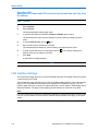
Video List Page . . . . . . . . . . . . . . . . . . . . . . . . . . . . . . . . . . . . . . . . . . . . . . . . . . 43
Alarms Page . . . . . . . . . . . . . . . . . . . . . . . . . . . . . . . . . . . . . . . . . . . . . . . . . . . . 45
Storage. . . . . . . . . . . . . . . . . . . . . . . . . . . . . . . . . . . . . . . . . . . . . . . . . . . . . . . . . . . . 46
Basic Page . . . . . . . . . . . . . . . . . . . . . . . . . . . . . . . . . . . . . . . . . . . . . . . . . . . . . 46
Storage Sets Page . . . . . . . . . . . . . . . . . . . . . . . . . . . . . . . . . . . . . . . . . . . . . . . 48
Assign Cameras Page . . . . . . . . . . . . . . . . . . . . . . . . . . . . . . . . . . . . . . . . . . . . . 49
Email Alerts . . . . . . . . . . . . . . . . . . . . . . . . . . . . . . . . . . . . . . . . . . . . . . . . . . . . . . . . 50
Email Alerts Page . . . . . . . . . . . . . . . . . . . . . . . . . . . . . . . . . . . . . . . . . . . . . . . . 50
Finish . . . . . . . . . . . . . . . . . . . . . . . . . . . . . . . . . . . . . . . . . . . . . . . . . . . . . . . . . . . . . 51
Summary Page . . . . . . . . . . . . . . . . . . . . . . . . . . . . . . . . . . . . . . . . . . . . . . . . . . 51
Using the NVR Administration Interface
Overview. . . . . . . . . . . . . . . . . . . . . . . . . . . . . . . . . . . . . . . . . . . . . . . . . . . . . . . . . . . . . 53
Logging into the NVR Administrator Interface via a Web Browser . . . . . . . . . . . . . . . . . 53
victor NVR Administration Interface . . . . . . . . . . . . . . . . . . . . . . . . . . . . . . . . . . . . . . . . 54
Navigating the NVR Interface . . . . . . . . . . . . . . . . . . . . . . . . . . . . . . . . . . . . . . . . . . . . . 56
Live Video Menu . . . . . . . . . . . . . . . . . . . . . . . . . . . . . . . . . . . . . . . . . . . . . . . . . . . . 57
Devices Menu . . . . . . . . . . . . . . . . . . . . . . . . . . . . . . . . . . . . . . . . . . . . . . . . . . . . . . 57
Storage Menu. . . . . . . . . . . . . . . . . . . . . . . . . . . . . . . . . . . . . . . . . . . . . . . . . . . . . . . 57
Archive Menu . . . . . . . . . . . . . . . . . . . . . . . . . . . . . . . . . . . . . . . . . . . . . . . . . . . . . . . 57
System Menu . . . . . . . . . . . . . . . . . . . . . . . . . . . . . . . . . . . . . . . . . . . . . . . . . . . . . . . 57
Network Menu . . . . . . . . . . . . . . . . . . . . . . . . . . . . . . . . . . . . . . . . . . . . . . . . . . . . . . 58
Advanced Menu . . . . . . . . . . . . . . . . . . . . . . . . . . . . . . . . . . . . . . . . . . . . . . . . . . . . . 58
vi
VideoEdge NVR 4.4 Installation and User Manual
Table of Contents
Configuring Storage
Overview. . . . . . . . . . . . . . . . . . . . . . . . . . . . . . . . . . . . . . . . . . . . . . . . . . . . . . . . . . . . . 61
Overview of Storage Sets . . . . . . . . . . . . . . . . . . . . . . . . . . . . . . . . . . . . . . . . . . . . . 61
Verifying Storage Devices . . . . . . . . . . . . . . . . . . . . . . . . . . . . . . . . . . . . . . . . . . . . . . . 61
Basic Storage Configuration . . . . . . . . . . . . . . . . . . . . . . . . . . . . . . . . . . . . . . . . . . . . . . 62
Enabling Media Folders for Storage . . . . . . . . . . . . . . . . . . . . . . . . . . . . . . . . . . . . . . . . 63
Disabling Storage Media Folders . . . . . . . . . . . . . . . . . . . . . . . . . . . . . . . . . . . . . . . . . . 64
Allocating Storage Space for Media . . . . . . . . . . . . . . . . . . . . . . . . . . . . . . . . . . . . . . . . 65
Data Culling . . . . . . . . . . . . . . . . . . . . . . . . . . . . . . . . . . . . . . . . . . . . . . . . . . . . . . . . . . 65
Vaulted Media. . . . . . . . . . . . . . . . . . . . . . . . . . . . . . . . . . . . . . . . . . . . . . . . . . . . . . . . . 66
Vault Media Quota . . . . . . . . . . . . . . . . . . . . . . . . . . . . . . . . . . . . . . . . . . . . . . . . . . . 66
Advanced Storage Configuration . . . . . . . . . . . . . . . . . . . . . . . . . . . . . . . . . . . . . . . . . . 67
Creating Storage Sets . . . . . . . . . . . . . . . . . . . . . . . . . . . . . . . . . . . . . . . . . . . . . . . . . . 69
Storage Set Recommendations . . . . . . . . . . . . . . . . . . . . . . . . . . . . . . . . . . . . . . . . . 69
Media Folder Assignment for Storage Sets . . . . . . . . . . . . . . . . . . . . . . . . . . . . . . . . . . 69
Assigning Cameras to Storage Sets. . . . . . . . . . . . . . . . . . . . . . . . . . . . . . . . . . . . . . . . 70
Calibrating Cameras. . . . . . . . . . . . . . . . . . . . . . . . . . . . . . . . . . . . . . . . . . . . . . . . . . . . 71
Deleting Storage Sets. . . . . . . . . . . . . . . . . . . . . . . . . . . . . . . . . . . . . . . . . . . . . . . . . . . 72
Storage Statistics . . . . . . . . . . . . . . . . . . . . . . . . . . . . . . . . . . . . . . . . . . . . . . . . . . . . . . 72
Storage Monitoring . . . . . . . . . . . . . . . . . . . . . . . . . . . . . . . . . . . . . . . . . . . . . . . . . . . . . 73
Live Video
Overview. . . . . . . . . . . . . . . . . . . . . . . . . . . . . . . . . . . . . . . . . . . . . . . . . . . . . . . . . . . . . 75
Viewing Live View. . . . . . . . . . . . . . . . . . . . . . . . . . . . . . . . . . . . . . . . . . . . . . . . . . . . . . 75
Viewing Live Video with QuickTime . . . . . . . . . . . . . . . . . . . . . . . . . . . . . . . . . . . . . . . . 76
Devices
Overview. . . . . . . . . . . . . . . . . . . . . . . . . . . . . . . . . . . . . . . . . . . . . . . . . . . . . . . . . . . . . 79
Device List Summary Tables . . . . . . . . . . . . . . . . . . . . . . . . . . . . . . . . . . . . . . . . . . . . . 80
Video List . . . . . . . . . . . . . . . . . . . . . . . . . . . . . . . . . . . . . . . . . . . . . . . . . . . . . . . . . . 80
Audio List . . . . . . . . . . . . . . . . . . . . . . . . . . . . . . . . . . . . . . . . . . . . . . . . . . . . . . . . . . 82
Sorting the Device Lists . . . . . . . . . . . . . . . . . . . . . . . . . . . . . . . . . . . . . . . . . . . . . . . . . 83
Filtering the Device Lists . . . . . . . . . . . . . . . . . . . . . . . . . . . . . . . . . . . . . . . . . . . . . . . . 84
Device Types . . . . . . . . . . . . . . . . . . . . . . . . . . . . . . . . . . . . . . . . . . . . . . . . . . . . . . . . . 84
Cameras. . . . . . . . . . . . . . . . . . . . . . . . . . . . . . . . . . . . . . . . . . . . . . . . . . . . . . . . . . . 85
ONVIF . . . . . . . . . . . . . . . . . . . . . . . . . . . . . . . . . . . . . . . . . . . . . . . . . . . . . . . . . 85
Audio Devices . . . . . . . . . . . . . . . . . . . . . . . . . . . . . . . . . . . . . . . . . . . . . . . . . . . . . . 85
vii
Table of Contents
Adding Devices to the NVR . . . . . . . . . . . . . . . . . . . . . . . . . . . . . . . . . . . . . . . . . . . . . . 85
Manually Adding an IP Device . . . . . . . . . . . . . . . . . . . . . . . . . . . . . . . . . . . . . . . . . . 85
Adding Devices Using Auto-Discovery. . . . . . . . . . . . . . . . . . . . . . . . . . . . . . . . . . . . 87
Removing a Device . . . . . . . . . . . . . . . . . . . . . . . . . . . . . . . . . . . . . . . . . . . . . . . . . . 89
Sensors . . . . . . . . . . . . . . . . . . . . . . . . . . . . . . . . . . . . . . . . . . . . . . . . . . . . . . . . . . . . . 90
Device Configuration
Overview. . . . . . . . . . . . . . . . . . . . . . . . . . . . . . . . . . . . . . . . . . . . . . . . . . . . . . . . . . . . . 93
Device Configuration Using the Device Lists . . . . . . . . . . . . . . . . . . . . . . . . . . . . . . . . . 93
Batch Camera Configuration . . . . . . . . . . . . . . . . . . . . . . . . . . . . . . . . . . . . . . . . . . . . . 96
Advanced Camera Configuration . . . . . . . . . . . . . . . . . . . . . . . . . . . . . . . . . . . . . . . . . 100
Configuring General Camera Settings . . . . . . . . . . . . . . . . . . . . . . . . . . . . . . . . . . . 100
Edit a Camera Name . . . . . . . . . . . . . . . . . . . . . . . . . . . . . . . . . . . . . . . . . . . . . 101
Change the Password Group Assigned to an IP Camera . . . . . . . . . . . . . . . . . 101
Change a Camera’s Storage Set. . . . . . . . . . . . . . . . . . . . . . . . . . . . . . . . . . . . 102
Video Streaming . . . . . . . . . . . . . . . . . . . . . . . . . . . . . . . . . . . . . . . . . . . . . . . . 103
Look-Down . . . . . . . . . . . . . . . . . . . . . . . . . . . . . . . . . . . . . . . . . . . . . . . . . . . . 103
Configure Camera Image Settings. . . . . . . . . . . . . . . . . . . . . . . . . . . . . . . . . . . . . . 104
Configure Camera Function and Stream Settings . . . . . . . . . . . . . . . . . . . . . . . . . . 106
Set the Camera Recording Status . . . . . . . . . . . . . . . . . . . . . . . . . . . . . . . . . . . 107
Set a Camera Recording Retention Period . . . . . . . . . . . . . . . . . . . . . . . . . . . . 108
Configuring Audio Association. . . . . . . . . . . . . . . . . . . . . . . . . . . . . . . . . . . . . . 108
Configuring Camera Stream Settings . . . . . . . . . . . . . . . . . . . . . . . . . . . . . . . . 109
Configuring Archive Settings . . . . . . . . . . . . . . . . . . . . . . . . . . . . . . . . . . . . . . . . . . . . 110
Configuring Alert Buffer Settings . . . . . . . . . . . . . . . . . . . . . . . . . . . . . . . . . . . . . . . . . 111
Configuring Sensors . . . . . . . . . . . . . . . . . . . . . . . . . . . . . . . . . . . . . . . . . . . . . . . . . . . 112
Dry Contact Sensors . . . . . . . . . . . . . . . . . . . . . . . . . . . . . . . . . . . . . . . . . . . . . . . . 112
Configuring PTZ Settings . . . . . . . . . . . . . . . . . . . . . . . . . . . . . . . . . . . . . . . . . . . . . . . 112
Enable/Disable PTZ Functionality . . . . . . . . . . . . . . . . . . . . . . . . . . . . . . . . . . . . . . 113
Return to Home . . . . . . . . . . . . . . . . . . . . . . . . . . . . . . . . . . . . . . . . . . . . . . . . . . . . 113
Motion Detection
Overview. . . . . . . . . . . . . . . . . . . . . . . . . . . . . . . . . . . . . . . . . . . . . . . . . . . . . . . . . . . . 115
Motion Detection Best Practices . . . . . . . . . . . . . . . . . . . . . . . . . . . . . . . . . . . . . . . . . 115
Enabling Motion Detection . . . . . . . . . . . . . . . . . . . . . . . . . . . . . . . . . . . . . . . . . . . . . . 116
Disabling Motion Detection . . . . . . . . . . . . . . . . . . . . . . . . . . . . . . . . . . . . . . . . . . . . . . 118
Motion Detection Alarms . . . . . . . . . . . . . . . . . . . . . . . . . . . . . . . . . . . . . . . . . . . . . . . 118
Creating a Motion Detection Camera Alarm . . . . . . . . . . . . . . . . . . . . . . . . . . . . . . 121
Editing a Motion Detection Camera Alarm . . . . . . . . . . . . . . . . . . . . . . . . . . . . . . . . 123
Disabling a Motion Detection Camera Alarm . . . . . . . . . . . . . . . . . . . . . . . . . . . . . . 123
viii
VideoEdge NVR 4.4 Installation and User Manual
Table of Contents
Deleting a Motion Detection Camera Alarm. . . . . . . . . . . . . . . . . . . . . . . . . . . . . . . 124
Video Intelligence
Overview. . . . . . . . . . . . . . . . . . . . . . . . . . . . . . . . . . . . . . . . . . . . . . . . . . . . . . . . . . . . 125
Video Intelligence Best Practices . . . . . . . . . . . . . . . . . . . . . . . . . . . . . . . . . . . . . . . . . 126
Enable Video Intelligence for a Camera . . . . . . . . . . . . . . . . . . . . . . . . . . . . . . . . . . . . 127
Disable Video Intelligence for a Camera . . . . . . . . . . . . . . . . . . . . . . . . . . . . . . . . . . . 128
Video Intelligence Camera Alarms . . . . . . . . . . . . . . . . . . . . . . . . . . . . . . . . . . . . . . . . 129
Creating a Video Intelligence Camera Alarm . . . . . . . . . . . . . . . . . . . . . . . . . . . . . . 130
Editing a Video Intelligence Camera Alarm . . . . . . . . . . . . . . . . . . . . . . . . . . . . . . . 132
Disabling Video Intelligence Camera Alarm. . . . . . . . . . . . . . . . . . . . . . . . . . . . . . . 133
Deleting a Video Intelligence Camera Alarm . . . . . . . . . . . . . . . . . . . . . . . . . . . . . . 134
Edge Analytics
Overview. . . . . . . . . . . . . . . . . . . . . . . . . . . . . . . . . . . . . . . . . . . . . . . . . . . . . . . . . . . . 135
Edge Analytics Best Practices . . . . . . . . . . . . . . . . . . . . . . . . . . . . . . . . . . . . . . . . . . . 136
Enabling Edge Based Analytics . . . . . . . . . . . . . . . . . . . . . . . . . . . . . . . . . . . . . . . . . . 136
Disabling Edge Based Analytics for a Camera. . . . . . . . . . . . . . . . . . . . . . . . . . . . . . . 138
Edge Based Analytic Alarms and Metadata . . . . . . . . . . . . . . . . . . . . . . . . . . . . . . . . . 138
Edge Based Analytic Alarms . . . . . . . . . . . . . . . . . . . . . . . . . . . . . . . . . . . . . . . . . . 138
Edge Based Analytic Metadata . . . . . . . . . . . . . . . . . . . . . . . . . . . . . . . . . . . . . . . . 139
Enabling/Disabling an Edge Based Camera Alarm . . . . . . . . . . . . . . . . . . . . . . . . . 139
Camera Scheduler
Overview. . . . . . . . . . . . . . . . . . . . . . . . . . . . . . . . . . . . . . . . . . . . . . . . . . . . . . . . . . . . 141
Create a Recording Schedule . . . . . . . . . . . . . . . . . . . . . . . . . . . . . . . . . . . . . . . . . . . 141
Enabling/Disabling the Recording Schedule . . . . . . . . . . . . . . . . . . . . . . . . . . . . . . . . 144
Editing the Recording Schedule . . . . . . . . . . . . . . . . . . . . . . . . . . . . . . . . . . . . . . . . . . 145
Edit the Group Name . . . . . . . . . . . . . . . . . . . . . . . . . . . . . . . . . . . . . . . . . . . . . . . . 145
Edit the Recording Scheduler for a Group . . . . . . . . . . . . . . . . . . . . . . . . . . . . . . . . 145
Edit the Cameras Assigned to a Schedule Group . . . . . . . . . . . . . . . . . . . . . . . . . . 146
Remove a Schedule Group . . . . . . . . . . . . . . . . . . . . . . . . . . . . . . . . . . . . . . . . . . . . . 146
ix
Table of Contents
Camera Password Groups
Overview. . . . . . . . . . . . . . . . . . . . . . . . . . . . . . . . . . . . . . . . . . . . . . . . . . . . . . . . . . . . 149
Create a Password Group . . . . . . . . . . . . . . . . . . . . . . . . . . . . . . . . . . . . . . . . . . . . . . 149
Delete a Password Group . . . . . . . . . . . . . . . . . . . . . . . . . . . . . . . . . . . . . . . . . . . . . . 151
Basic System Settings
Overview. . . . . . . . . . . . . . . . . . . . . . . . . . . . . . . . . . . . . . . . . . . . . . . . . . . . . . . . . . . . 153
General System Information . . . . . . . . . . . . . . . . . . . . . . . . . . . . . . . . . . . . . . . . . . . . . 153
Hostname. . . . . . . . . . . . . . . . . . . . . . . . . . . . . . . . . . . . . . . . . . . . . . . . . . . . . . . . . 154
Location . . . . . . . . . . . . . . . . . . . . . . . . . . . . . . . . . . . . . . . . . . . . . . . . . . . . . . . . . . 155
Current Date and Time. . . . . . . . . . . . . . . . . . . . . . . . . . . . . . . . . . . . . . . . . . . . . . . 155
Changing the Selected Language . . . . . . . . . . . . . . . . . . . . . . . . . . . . . . . . . . . . . . 156
Downloading the Public Key . . . . . . . . . . . . . . . . . . . . . . . . . . . . . . . . . . . . . . . . . . 157
Users and Roles . . . . . . . . . . . . . . . . . . . . . . . . . . . . . . . . . . . . . . . . . . . . . . . . . . . . . . 157
Users Page . . . . . . . . . . . . . . . . . . . . . . . . . . . . . . . . . . . . . . . . . . . . . . . . . . . . . . . 157
Add a New User . . . . . . . . . . . . . . . . . . . . . . . . . . . . . . . . . . . . . . . . . . . . . . . . 158
Reset a Password . . . . . . . . . . . . . . . . . . . . . . . . . . . . . . . . . . . . . . . . . . . . . . . 159
Changing the Default Role Passwords . . . . . . . . . . . . . . . . . . . . . . . . . . . . . . . 160
Remove a User . . . . . . . . . . . . . . . . . . . . . . . . . . . . . . . . . . . . . . . . . . . . . . . . . 160
Roles Page. . . . . . . . . . . . . . . . . . . . . . . . . . . . . . . . . . . . . . . . . . . . . . . . . . . . . . . . 161
Editing the Lockout Policy . . . . . . . . . . . . . . . . . . . . . . . . . . . . . . . . . . . . . . . . . 161
Locked Accounts . . . . . . . . . . . . . . . . . . . . . . . . . . . . . . . . . . . . . . . . . . . . . . . . 162
Licensing the NVR
Overview. . . . . . . . . . . . . . . . . . . . . . . . . . . . . . . . . . . . . . . . . . . . . . . . . . . . . . . . . . . . 165
Licensing the NVR . . . . . . . . . . . . . . . . . . . . . . . . . . . . . . . . . . . . . . . . . . . . . . . . . . . . 166
Generate a Host ID . . . . . . . . . . . . . . . . . . . . . . . . . . . . . . . . . . . . . . . . . . . . . . . . . 166
Apply a Software Licence. . . . . . . . . . . . . . . . . . . . . . . . . . . . . . . . . . . . . . . . . . . . . 167
Software Service Agreement Notifications . . . . . . . . . . . . . . . . . . . . . . . . . . . . . . . . . . 167
Edit the SSA Message . . . . . . . . . . . . . . . . . . . . . . . . . . . . . . . . . . . . . . . . . . . . . . . 167
Edit SSA Contacts . . . . . . . . . . . . . . . . . . . . . . . . . . . . . . . . . . . . . . . . . . . . . . . . . . 168
Set the SMTP Server Address . . . . . . . . . . . . . . . . . . . . . . . . . . . . . . . . . . . . . . . . . 169
Send an SSA Test Message . . . . . . . . . . . . . . . . . . . . . . . . . . . . . . . . . . . . . . . . . . 169
Network Settings
Overview. . . . . . . . . . . . . . . . . . . . . . . . . . . . . . . . . . . . . . . . . . . . . . . . . . . . . . . . . . . . 171
Configuring the NVR Network Settings . . . . . . . . . . . . . . . . . . . . . . . . . . . . . . . . . . . . 171
General Network Settings. . . . . . . . . . . . . . . . . . . . . . . . . . . . . . . . . . . . . . . . . . . . . . . 172
Domain Name and Domain Name Servers . . . . . . . . . . . . . . . . . . . . . . . . . . . . . . . 173
x
VideoEdge NVR 4.4 Installation and User Manual
Table of Contents
Default Gateway. . . . . . . . . . . . . . . . . . . . . . . . . . . . . . . . . . . . . . . . . . . . . . . . . . . . 174
RTSP Port . . . . . . . . . . . . . . . . . . . . . . . . . . . . . . . . . . . . . . . . . . . . . . . . . . . . . . . . 174
NTP Status and NTP Servers . . . . . . . . . . . . . . . . . . . . . . . . . . . . . . . . . . . . . . . . . 175
LAN Interface Settings . . . . . . . . . . . . . . . . . . . . . . . . . . . . . . . . . . . . . . . . . . . . . . . . . 176
DHCP Server Settings . . . . . . . . . . . . . . . . . . . . . . . . . . . . . . . . . . . . . . . . . . . . . . . . . 179
WAN Settings . . . . . . . . . . . . . . . . . . . . . . . . . . . . . . . . . . . . . . . . . . . . . . . . . . . . . . . . 181
WAN IP Address . . . . . . . . . . . . . . . . . . . . . . . . . . . . . . . . . . . . . . . . . . . . . . . . . . . 182
HTTP Port . . . . . . . . . . . . . . . . . . . . . . . . . . . . . . . . . . . . . . . . . . . . . . . . . . . . . . . . 183
Secure HTTP Port . . . . . . . . . . . . . . . . . . . . . . . . . . . . . . . . . . . . . . . . . . . . . . . . . . 184
Streaming Configured Port. . . . . . . . . . . . . . . . . . . . . . . . . . . . . . . . . . . . . . . . . . . . 185
Allowed IP Addresses . . . . . . . . . . . . . . . . . . . . . . . . . . . . . . . . . . . . . . . . . . . . . . . 185
Dynamic Bandwidth . . . . . . . . . . . . . . . . . . . . . . . . . . . . . . . . . . . . . . . . . . . . . . . . . . . 186
Bandwidth Priority . . . . . . . . . . . . . . . . . . . . . . . . . . . . . . . . . . . . . . . . . . . . . . . . . . 186
Traffic Smoothing Only . . . . . . . . . . . . . . . . . . . . . . . . . . . . . . . . . . . . . . . . . . . 187
Preserve Framerate. . . . . . . . . . . . . . . . . . . . . . . . . . . . . . . . . . . . . . . . . . . . . . 188
Preserve Resolution . . . . . . . . . . . . . . . . . . . . . . . . . . . . . . . . . . . . . . . . . . . . . 189
Allow Any Throttle Type. . . . . . . . . . . . . . . . . . . . . . . . . . . . . . . . . . . . . . . . . . . 190
Archiving
Overview. . . . . . . . . . . . . . . . . . . . . . . . . . . . . . . . . . . . . . . . . . . . . . . . . . . . . . . . . . . . 193
Adding an Archive Destination . . . . . . . . . . . . . . . . . . . . . . . . . . . . . . . . . . . . . . . . . . . 194
Editing Settings in the Archives Table . . . . . . . . . . . . . . . . . . . . . . . . . . . . . . . . . . . 195
Locked and Unlocked Archives . . . . . . . . . . . . . . . . . . . . . . . . . . . . . . . . . . . . . . . . 196
Enabling/Disabling an Archive Destination . . . . . . . . . . . . . . . . . . . . . . . . . . . . . . . . . . 197
Global Settings . . . . . . . . . . . . . . . . . . . . . . . . . . . . . . . . . . . . . . . . . . . . . . . . . . . . . . . 198
Configuring an Archive Availability Schedule . . . . . . . . . . . . . . . . . . . . . . . . . . . . . . . . 199
Manually Archiving Video . . . . . . . . . . . . . . . . . . . . . . . . . . . . . . . . . . . . . . . . . . . . . . . 200
Viewing and Deleting Manual Archiving Tasks . . . . . . . . . . . . . . . . . . . . . . . . . . . . 200
Automatic Archiving of Video . . . . . . . . . . . . . . . . . . . . . . . . . . . . . . . . . . . . . . . . . . . . 201
Schedules page . . . . . . . . . . . . . . . . . . . . . . . . . . . . . . . . . . . . . . . . . . . . . . . . . . . . 201
Schedule Editor and Group Editor Pages . . . . . . . . . . . . . . . . . . . . . . . . . . . . . . . . 203
Archiving Quality (Framerate Decimation) . . . . . . . . . . . . . . . . . . . . . . . . . . . . . . . . 205
Setting the Archive Bitrate Cap . . . . . . . . . . . . . . . . . . . . . . . . . . . . . . . . . . . . . . . . . . 206
Retrieving Archived Video Using victor unified client . . . . . . . . . . . . . . . . . . . . . . . . . . 207
Viewing Archived Video in a 3rd Party Media Player . . . . . . . . . . . . . . . . . . . . . . . . . . 207
Archive Management . . . . . . . . . . . . . . . . . . . . . . . . . . . . . . . . . . . . . . . . . . . . . . . . . . 208
Maximum Archiving Retention Period . . . . . . . . . . . . . . . . . . . . . . . . . . . . . . . . . . . . . 208
NVR Failover
Overview. . . . . . . . . . . . . . . . . . . . . . . . . . . . . . . . . . . . . . . . . . . . . . . . . . . . . . . . . . . . 211
How Failover is Initiated . . . . . . . . . . . . . . . . . . . . . . . . . . . . . . . . . . . . . . . . . . . . . . 212
xi
Table of Contents
Alerts . . . . . . . . . . . . . . . . . . . . . . . . . . . . . . . . . . . . . . . . . . . . . . . . . . . . . . . . . . . . 212
Virtual IP Addresses. . . . . . . . . . . . . . . . . . . . . . . . . . . . . . . . . . . . . . . . . . . . . . . . . 213
Using an NVR in Failover Mode. . . . . . . . . . . . . . . . . . . . . . . . . . . . . . . . . . . . . . . . 213
Events . . . . . . . . . . . . . . . . . . . . . . . . . . . . . . . . . . . . . . . . . . . . . . . . . . . . . . . . . . . 213
Backup/Restore . . . . . . . . . . . . . . . . . . . . . . . . . . . . . . . . . . . . . . . . . . . . . . . . . . . . 214
Upgrade Considerations . . . . . . . . . . . . . . . . . . . . . . . . . . . . . . . . . . . . . . . . . . . . . 214
Recommended Method - Upgrading the Secondary First . . . . . . . . . . . . . . . . . 214
Upgrade the Secondary Last . . . . . . . . . . . . . . . . . . . . . . . . . . . . . . . . . . . . . . . 214
Configure Failover Mode for an NVR . . . . . . . . . . . . . . . . . . . . . . . . . . . . . . . . . . . . . . 214
Failover Advanced Configuration . . . . . . . . . . . . . . . . . . . . . . . . . . . . . . . . . . . . . . . 215
Adding a Primary NVR for Monitoring to the Secondary NVR . . . . . . . . . . . . . . . . . 216
Configuring Failover Parameters . . . . . . . . . . . . . . . . . . . . . . . . . . . . . . . . . . . . . . . 217
Terminating Failover Mode When Primary NVR is Operational . . . . . . . . . . . . . . . . . . 218
Starting and Stopping Server Monitoring . . . . . . . . . . . . . . . . . . . . . . . . . . . . . . . . . . . 219
Editing Primary NVR Monitoring Settings in the Server Monitoring List . . . . . . . . . . . . 219
Removing Primary NVRs from the Server Monitoring List . . . . . . . . . . . . . . . . . . . . . . 220
Testing Failover on the Secondary NVR . . . . . . . . . . . . . . . . . . . . . . . . . . . . . . . . . . . 221
If Failover Doesn’t Occur . . . . . . . . . . . . . . . . . . . . . . . . . . . . . . . . . . . . . . . . . . . . . 221
Failover Events Report . . . . . . . . . . . . . . . . . . . . . . . . . . . . . . . . . . . . . . . . . . . . . . . . . 222
Disabling the Failover Mode on an NVR . . . . . . . . . . . . . . . . . . . . . . . . . . . . . . . . . . . 223
Configuration Backup and Templates
Overview. . . . . . . . . . . . . . . . . . . . . . . . . . . . . . . . . . . . . . . . . . . . . . . . . . . . . . . . . . . . 225
Configuration Backup and Restore. . . . . . . . . . . . . . . . . . . . . . . . . . . . . . . . . . . . . . . . 225
Create a Configuration Backup File . . . . . . . . . . . . . . . . . . . . . . . . . . . . . . . . . . . . . 226
Restore an NVR . . . . . . . . . . . . . . . . . . . . . . . . . . . . . . . . . . . . . . . . . . . . . . . . . . . . 227
Templates. . . . . . . . . . . . . . . . . . . . . . . . . . . . . . . . . . . . . . . . . . . . . . . . . . . . . . . . . . . 228
Save a Configuration Template . . . . . . . . . . . . . . . . . . . . . . . . . . . . . . . . . . . . . . . . 229
Import a Template File . . . . . . . . . . . . . . . . . . . . . . . . . . . . . . . . . . . . . . . . . . . . . . . 230
xii
VideoEdge NVR 4.4 Installation and User Manual
Table of Contents
System Shutdown and Reset Factory Defaults
Overview. . . . . . . . . . . . . . . . . . . . . . . . . . . . . . . . . . . . . . . . . . . . . . . . . . . . . . . . . . . . 231
Restart NVR Services. . . . . . . . . . . . . . . . . . . . . . . . . . . . . . . . . . . . . . . . . . . . . . . . . . 231
Stop NVR Services. . . . . . . . . . . . . . . . . . . . . . . . . . . . . . . . . . . . . . . . . . . . . . . . . . . . 232
Reboot the NVR . . . . . . . . . . . . . . . . . . . . . . . . . . . . . . . . . . . . . . . . . . . . . . . . . . . . . . 233
Shutdown the NVR . . . . . . . . . . . . . . . . . . . . . . . . . . . . . . . . . . . . . . . . . . . . . . . . . . . . 233
Reset Factory Defaults . . . . . . . . . . . . . . . . . . . . . . . . . . . . . . . . . . . . . . . . . . . . . . . . . 234
Operational Statistics
Overview. . . . . . . . . . . . . . . . . . . . . . . . . . . . . . . . . . . . . . . . . . . . . . . . . . . . . . . . . . . . 237
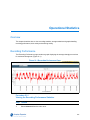
Recording Performance . . . . . . . . . . . . . . . . . . . . . . . . . . . . . . . . . . . . . . . . . . . . . . . . 237
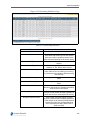
Video Recording Statistics . . . . . . . . . . . . . . . . . . . . . . . . . . . . . . . . . . . . . . . . . . . . . . 238
Disk Activity . . . . . . . . . . . . . . . . . . . . . . . . . . . . . . . . . . . . . . . . . . . . . . . . . . . . . . . . . 241
Storage Statistics . . . . . . . . . . . . . . . . . . . . . . . . . . . . . . . . . . . . . . . . . . . . . . . . . . . . . 242
Storage Set Statistics. . . . . . . . . . . . . . . . . . . . . . . . . . . . . . . . . . . . . . . . . . . . . . . . 242
Storage Device Statistics . . . . . . . . . . . . . . . . . . . . . . . . . . . . . . . . . . . . . . . . . . . . . 244
Storage Statistics per Video Device. . . . . . . . . . . . . . . . . . . . . . . . . . . . . . . . . . . . . 245
Viewing Archive Statistics in the NVR Administration Interface . . . . . . . . . . . . . . . . . . 247
Logs
Overview. . . . . . . . . . . . . . . . . . . . . . . . . . . . . . . . . . . . . . . . . . . . . . . . . . . . . . . . . . . . 249
Retrieving Logs. . . . . . . . . . . . . . . . . . . . . . . . . . . . . . . . . . . . . . . . . . . . . . . . . . . . . . . 249
FTP Log Management . . . . . . . . . . . . . . . . . . . . . . . . . . . . . . . . . . . . . . . . . . . . . . . . . 251
Event Logs . . . . . . . . . . . . . . . . . . . . . . . . . . . . . . . . . . . . . . . . . . . . . . . . . . . . . . . . . . 252
Camera Connection Errors. . . . . . . . . . . . . . . . . . . . . . . . . . . . . . . . . . . . . . . . . . . . . . 253
Camera Logs . . . . . . . . . . . . . . . . . . . . . . . . . . . . . . . . . . . . . . . . . . . . . . . . . . . . . . . . 254
Audit Trail . . . . . . . . . . . . . . . . . . . . . . . . . . . . . . . . . . . . . . . . . . . . . . . . . . . . . . . . . . . 255
Viewing Connected Clients. . . . . . . . . . . . . . . . . . . . . . . . . . . . . . . . . . . . . . . . . . . . . . 256
Email Alerts
Overview. . . . . . . . . . . . . . . . . . . . . . . . . . . . . . . . . . . . . . . . . . . . . . . . . . . . . . . . . . . . 259
Advance Preparation . . . . . . . . . . . . . . . . . . . . . . . . . . . . . . . . . . . . . . . . . . . . . . . . . . 260
Setting Up Email Alerts. . . . . . . . . . . . . . . . . . . . . . . . . . . . . . . . . . . . . . . . . . . . . . . . . 261
SMTP Server IP Address . . . . . . . . . . . . . . . . . . . . . . . . . . . . . . . . . . . . . . . . . . . . . 261
Building the Recipient List . . . . . . . . . . . . . . . . . . . . . . . . . . . . . . . . . . . . . . . . . . . . 262
Enabling and Disabling Email Alerts . . . . . . . . . . . . . . . . . . . . . . . . . . . . . . . . . . . . 263
xiii
Table of Contents
Disabling Email Alerts for a Camera . . . . . . . . . . . . . . . . . . . . . . . . . . . . . . . . . . . . 264
Removing an Address from the Recipient List . . . . . . . . . . . . . . . . . . . . . . . . . . . . . 265
Alert Logs . . . . . . . . . . . . . . . . . . . . . . . . . . . . . . . . . . . . . . . . . . . . . . . . . . . . . . . . . 266
Clearing the Alert Logs Page . . . . . . . . . . . . . . . . . . . . . . . . . . . . . . . . . . . . . . . . . . 267
Dark Image Detection
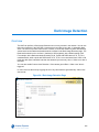
Overview. . . . . . . . . . . . . . . . . . . . . . . . . . . . . . . . . . . . . . . . . . . . . . . . . . . . . . . . . . . . 269
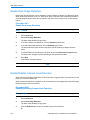
Enable Dark Image Detection. . . . . . . . . . . . . . . . . . . . . . . . . . . . . . . . . . . . . . . . . . . . 270
Enable/Disable Camera Loss Detection . . . . . . . . . . . . . . . . . . . . . . . . . . . . . . . . . . . . 270
Software Updates
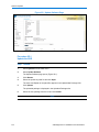
Overview. . . . . . . . . . . . . . . . . . . . . . . . . . . . . . . . . . . . . . . . . . . . . . . . . . . . . . . . . . . . 273
Push Updates . . . . . . . . . . . . . . . . . . . . . . . . . . . . . . . . . . . . . . . . . . . . . . . . . . . . . . . . 273
Applying Software Updates using the Administration Interface . . . . . . . . . . . . . . . . . . 273
Updating Camera Handler Packs . . . . . . . . . . . . . . . . . . . . . . . . . . . . . . . . . . . . . . . . . 275
Failover Considerations . . . . . . . . . . . . . . . . . . . . . . . . . . . . . . . . . . . . . . . . . . . . . . . . 275
Appendix A: Storage
Overview. . . . . . . . . . . . . . . . . . . . . . . . . . . . . . . . . . . . . . . . . . . . . . . . . . . . . . . . . . . . 277
Storage Concepts. . . . . . . . . . . . . . . . . . . . . . . . . . . . . . . . . . . . . . . . . . . . . . . . . . . . . 277
iSCSI . . . . . . . . . . . . . . . . . . . . . . . . . . . . . . . . . . . . . . . . . . . . . . . . . . . . . . . . . . . . 277
Fiber Channel. . . . . . . . . . . . . . . . . . . . . . . . . . . . . . . . . . . . . . . . . . . . . . . . . . . . . . 277
Direct Attached Storage . . . . . . . . . . . . . . . . . . . . . . . . . . . . . . . . . . . . . . . . . . . . . . 278
Storage Types . . . . . . . . . . . . . . . . . . . . . . . . . . . . . . . . . . . . . . . . . . . . . . . . . . . . . 278
JBOD . . . . . . . . . . . . . . . . . . . . . . . . . . . . . . . . . . . . . . . . . . . . . . . . . . . . . . . . . 278
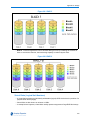
RAID . . . . . . . . . . . . . . . . . . . . . . . . . . . . . . . . . . . . . . . . . . . . . . . . . . . . . . . . . 278
Virtual Disks (Logical Unit Numbers) . . . . . . . . . . . . . . . . . . . . . . . . . . . . . . . . . 279
Storage Strategy. . . . . . . . . . . . . . . . . . . . . . . . . . . . . . . . . . . . . . . . . . . . . . . . . . . . . . 280
Understanding Storage Sets . . . . . . . . . . . . . . . . . . . . . . . . . . . . . . . . . . . . . . . . . . . . 281
Calculating Storage Requirements . . . . . . . . . . . . . . . . . . . . . . . . . . . . . . . . . . . . . . . . 282
Overview of AD Fiber RAID Storage (FRS/FES) . . . . . . . . . . . . . . . . . . . . . . . . . . . . . 283
Second generation American Dynamics iSCSI and Fiber RAID Storage . . . . . . . . 284
Storage Strategy for FRS/FES RAID Device . . . . . . . . . . . . . . . . . . . . . . . . . . . . . . 284
Recommendations. . . . . . . . . . . . . . . . . . . . . . . . . . . . . . . . . . . . . . . . . . . . . . . 284
Connecting Additional Storage Devices. . . . . . . . . . . . . . . . . . . . . . . . . . . . . . . . . . 284
Connecting NVR to FRS/FES Using Fiber . . . . . . . . . . . . . . . . . . . . . . . . . . . . 284
Connecting NVR to FRS/FES Using iSCSI . . . . . . . . . . . . . . . . . . . . . . . . . . . . 286
xiv
VideoEdge NVR 4.4 Installation and User Manual
Table of Contents
Appendix B: Web Client Pre-configuration
Overview. . . . . . . . . . . . . . . . . . . . . . . . . . . . . . . . . . . . . . . . . . . . . . . . . . . . . . . . . . . . 293
Prerequisite Software . . . . . . . . . . . . . . . . . . . . . . . . . . . . . . . . . . . . . . . . . . . . . . . . . . 293
Specifying the NVR as a trusted site in Internet Explorer. . . . . . . . . . . . . . . . . . . . . . . 293
Configuring the Paging File . . . . . . . . . . . . . . . . . . . . . . . . . . . . . . . . . . . . . . . . . . . . . 294
Setting QuickTime Preferences . . . . . . . . . . . . . . . . . . . . . . . . . . . . . . . . . . . . . . . . . . 297
Setting QuickTime Preferences (XP) . . . . . . . . . . . . . . . . . . . . . . . . . . . . . . . . . . . . 297
Setting QuickTime Preferences (Windows 7) . . . . . . . . . . . . . . . . . . . . . . . . . . . . . 298
Appendix C: Networking Troubleshooting
Overview. . . . . . . . . . . . . . . . . . . . . . . . . . . . . . . . . . . . . . . . . . . . . . . . . . . . . . . . . . . . 301
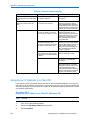
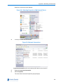
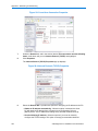
Assigning an IP Address to a Client PC . . . . . . . . . . . . . . . . . . . . . . . . . . . . . . . . . . . . 302
Troubleshooting Network Connections. . . . . . . . . . . . . . . . . . . . . . . . . . . . . . . . . . . . . 308
Launching the Windows Command Prompt . . . . . . . . . . . . . . . . . . . . . . . . . . . . . . . . . 309
Troubleshooting with the Ipconfig /All Command . . . . . . . . . . . . . . . . . . . . . . . . . . . . . 311
Troubleshooting with the Ping Command. . . . . . . . . . . . . . . . . . . . . . . . . . . . . . . . . . . 313
Troubleshooting with the Tracert Command . . . . . . . . . . . . . . . . . . . . . . . . . . . . . . . . 314
Appendix D: NVR Troubleshooting
Overview. . . . . . . . . . . . . . . . . . . . . . . . . . . . . . . . . . . . . . . . . . . . . . . . . . . . . . . . . . . . 317
Monitor Resolution Settings . . . . . . . . . . . . . . . . . . . . . . . . . . . . . . . . . . . . . . . . . . . . . 317
Changing the Monitor Resolution. . . . . . . . . . . . . . . . . . . . . . . . . . . . . . . . . . . . . . . 317
Enabling Remote Desktop . . . . . . . . . . . . . . . . . . . . . . . . . . . . . . . . . . . . . . . . . . . . . . 318
Enabling RDP Remote Desktop. . . . . . . . . . . . . . . . . . . . . . . . . . . . . . . . . . . . . . . . 319
Enabling VNC Remote Desktop. . . . . . . . . . . . . . . . . . . . . . . . . . . . . . . . . . . . . . . . 320
Accessing the Remote Desktop . . . . . . . . . . . . . . . . . . . . . . . . . . . . . . . . . . . . . . . . . . 322
RDP Remote Desktop . . . . . . . . . . . . . . . . . . . . . . . . . . . . . . . . . . . . . . . . . . . . . . . 322
Logging Out of RDP Remote Desktop . . . . . . . . . . . . . . . . . . . . . . . . . . . . . . . . . . . 324
VNC Remote Desktop . . . . . . . . . . . . . . . . . . . . . . . . . . . . . . . . . . . . . . . . . . . . . . . 325
Editing the Network Settings Using Control Center . . . . . . . . . . . . . . . . . . . . . . . . . 328
Editing Storage Partitions Using Partitioner . . . . . . . . . . . . . . . . . . . . . . . . . . . . . . . . . 330
Configuring System Partitions on a Previously Configured Device . . . . . . . . . . . . . 330
Editing Media Partition Configurations . . . . . . . . . . . . . . . . . . . . . . . . . . . . . . . . . . . . . 331
System Disk Recovery . . . . . . . . . . . . . . . . . . . . . . . . . . . . . . . . . . . . . . . . . . . . . . . . . 333
VideoEdge NVR . . . . . . . . . . . . . . . . . . . . . . . . . . . . . . . . . . . . . . . . . . . . . . . . . . . . 333
xv
Table of Contents
Appendix E: Upgrading your NVR 4.1
Overview. . . . . . . . . . . . . . . . . . . . . . . . . . . . . . . . . . . . . . . . . . . . . . . . . . . . . . . . . . . . 337
Download and Deletion of NVR 4.1 ISO Files . . . . . . . . . . . . . . . . . . . . . . . . . . . . . 337
NVR 4.1 to NVR 4.2.1 Upgrade . . . . . . . . . . . . . . . . . . . . . . . . . . . . . . . . . . . . . . . . . . 338
Using the 4.1 Upgrade Tool to Launch the YaST Wizard . . . . . . . . . . . . . . . . . . . . 340
Using the YaST Wizard . . . . . . . . . . . . . . . . . . . . . . . . . . . . . . . . . . . . . . . . . . . . . . 342
Completing the Upgrade . . . . . . . . . . . . . . . . . . . . . . . . . . . . . . . . . . . . . . . . . . . . . 346
Changing the Disk Boot Order . . . . . . . . . . . . . . . . . . . . . . . . . . . . . . . . . . . . . . . . . 350
NVR 4.1 to 4.2.1 Migration Failure Recovery . . . . . . . . . . . . . . . . . . . . . . . . . . . . . . . . 350
End User License Agreement (EULA)
xvi
353
VideoEdge NVR 4.4 Installation and User Manual
Overview of the VideoEdge NVR
NVR Introduction
The VideoEdge Network Video Management System is a scalable enterprise IP video surveillance
solution. It is designed as an open platform solution supporting a range of third party hardware,
storage, video devices, and clients, allowing users to manage their video surveillance servers and
edge devices as a single logical system.
The VideoEdge Network Video Recorder (NVR) manages the IP encoder and camera devices,
records the video onto its configured storage devices, and provides clients with secure access to
live and recorded video and audio. Users can use a thin-client (NVR Administration Interface)or
the victor rich-client application software to configure the NVR or access the video/audio streams.
Purpose of the NVR
The NVR is the backbone for an IP-based video security system. The NVR uses TCP/IP
communication to access and control the hardware networked to it. The server can be controlled
directly by logging into its Administration interface homepage using a web browser or accessing it
via the victor rich-client application software. Worldwide access to the NVR gives it excellent
portability - any place where you have a personal computer with internet access to the web, you’ve
got access to your video security system.
An NVR gives you control over all the features of the surveillance and security hardware
networked to the NVR. Thus, from your web browser or via victor, you have control over your
entire video security system.
The NVR is available as either a bundled hardware solution or as software-only model that
transforms a standard computer hardware system into an advanced and powerful NVR server.
The NVR software is a hardware-independent platform. It supports major-brand IP cameras and
encoder devices, integrates into a TCP/IP networking environment, turning an ordinary PC or
server into an Enterprise Network Video Recorder.
victor Digital Video Management System
The “open” architecture of the victor Digital Video Management System line is designed so that
each component can operate independently, and can interact with software applications from other
product lines. The victor Digital Video Management System line includes products to address the
needs of a wide range of users.
1
Overview of the VideoEdge NVR
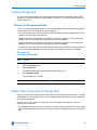
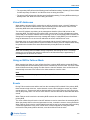
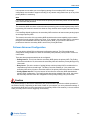
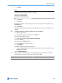
As the architecture is open, it is independent of specific hardware platforms. The NVR does not
require an existing operating system as it includes it’s own Linux-based operating system that can
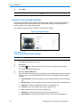
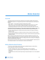
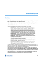
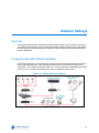
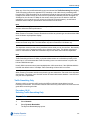
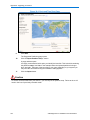
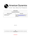
support a variety of different hardware platforms. Figure 1-1 shows how the NVR fits into the victor
Network Video Management System.
Figure 1-1 VideoEdge Network Video Components
The NVR manages the video camera, storage, and sensor assets for your site. Refer to Getting
Started with VideoEdge NVR on page 2 for more information on using the NVR.
You use the NVR Administration Interface to configure and manage the NVR via a web browser.
You can use these web pages to configure the NVR and its storage, cameras, and devices.
Typically, the assets connected to the NVR are configured on a local TCP/IP network, isolated
from the larger network, and accessible to clients via the NVR and the victor site manager. Refer
to Using the NVR Administration Interface on page 53 for more information on using the NVR
software.
The victor site manager provides a single point of access for users to manage multiple NVRs. The
victor site manager utilizes SQL Server’s database functionality to provide authentication for
VideoEdge Clients, as well as central monitoring and administration of multiple recording platforms
over a Wide Area Network (WAN). Refer to the victor Configuration and User Guide for more
information on configuring and using the victor site manager software. The victor clients are used
to monitor and configure one or more NVRs or other devices that are connected to the victor site
manager network. The victor client enables a user to login and access multiple NVRs from a single
Graphical User Interface (GUI). Refer to the victor Configuration and User Guide for more
information on using the victor client software.
Getting Started with VideoEdge NVR
This manual provides you with the information you need to install, configure and operate the
VideoEdge NVR. Some of the main sections of this manual and primary functions of the NVR are
outlined below, including references to the relevant sections in the manual to explain how to set up
and use the features.
System Configurations - provides information on the system configurations of the NVR units.
Refer to System Specifications on page 5.
2
VideoEdge NVR 4.4 Installation and User Manual
Overview of the VideoEdge NVR
Installation - provides instructions on how to install the NVR and configure it on the network.
Refer to Installing the VideoEdge NVR on page 7.
NVR Storage - provides information about the NVR physical storage of video, and instructions on
verifying and configuring storage and storage sets. Refer to Configuring Storage on page 61 or
Appendix A: Storage on page 277.
Using the NVR Administrator Interface - provides information on how to access the NVR
Administrator Interface via a web browser or via victor unified client and information on how to
navigate the interface. Refer to Using the NVR Administration Interface on page 53.
Device List - provides information on how to add IP cameras to the NVR manually or using AutoDiscovery. Refer to Live Video on page 75.
Device Configuration - provides information on how to configure cameras as individual cameras
or as a batch. Refer to Device Configuration on page 93.
Motion Detection - provides information on how to enable a camera for motion detection and
configure motion detection alarms. Refer to Motion Detection on page 115.
Video Intelligence - provides information on how to enable a camera for video intelligence and
configure video intelligence alarms. Refer to Video Intelligence on page 125.
Edge Analytics - provides information on how to enable and configure edge based analytic
alarms and metadata for a supported edge based camera. Refer to Edge Analytics on page 135.
Licensing the NVR - provides information on your current license, how to licence your NVR, how
to upgrade your licence and how to configure Software Service Agreement notifications. Refer to
Licensing the NVR on page 165.
Network Settings - provides information on the current NVR network settings, including LAN,
WAN, Dynamic Bandwidth and DHCP Server settings. It also provides information on how to edit
the current settings. Refer to Network Settings on page 171.
Archiving - provides information on how to configure archiving of video to Network Attached
Storage. Refer to Archiving on page 193.
Failover - provides information on how to configure the NVR as a Failover server. Refer to NVR
Failover on page 211.
Configuration Backup and Templates - provides information on how to create backup and
template files and how to configure the NVR using configurations saved in backup and template
files. Refer to Configuration Backup and Templates on page 225.
Updates - provides information on how to install system updates and patches and how to update
the camera handler packs. Refer to Software Updates on page 273.
3
Overview of the VideoEdge NVR
4
VideoEdge NVR 4.4 Installation and User Manual
System Specifications
Overview
The VideoEdge NVR release is available as a hardware and software bundle or as stand alone
software.
The bundled hardware and software is delivered with the software installed on the provided
hardware.
The software only model is distributed on a disk or USB drive. The NVR software can be installed
on any hardware platform that meets the recommended system specifications.
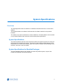
System Specifications
The hardware platforms that have been tested and qualified as supported systems for hosting the
NVR software are detailed in this section. The amount of video storage needed depends on site
requirements, such as the video retention period, the number of cameras, and the settings for the
resolution, frame rate, codec and quality.
System Specifications for Bundled Packages
The below hardware platforms are available, as tested and qualified systems, as part of the
bundled NVR hardware and software package.
5
System Specifications
Table 2-1 Hardware and Software Bundle System Specification
Processor
Single Intel E2620.
Memory
8GB (4 x 2GB modules).
System Drive
Minimum 500GB Hard-Drive
Video Storage
Minimum 500GB Hard-Drive.
RAID Controller
PERC H710 Integrated RAID Controller
Network Interface Cards
Minimum 2 x 1G NICs
Keyboard & Mouse
Required for installation and setup only.
Monitor
Required for installation and setup only.
Operating System
None (OS will be installed with the VideoEdge
Software)
Recommended System Specifications for Software Only
The following hardware platforms have been tested and qualified as supported systems for hosting
the NVR software.
Table 2-2 Recommended System Specification
Processor
Minimum Single Intel E2620.
Memory
Minimum 8GB (4 x 2GB modules).
System Drive
Minimum 500GB Hard-Drive
Video Storage
Minimum 500GB Hard-Drive.
RAID Controller
PERC H710 Integrated RAID Controller
Network Interface Cards
Minimum 2 x 1G NICs
Keyboard & Mouse
Required for installation and setup only.
Monitor
Required for installation and setup only.
Operating System
None (OS will be installed with the VideoEdge
Software)
Note
All hardware must be SUSE Linux certified.
6
VideoEdge NVR 4.4 Installation and User Manual
Installing the VideoEdge NVR
Overview
This chapter describes the installation and configuration process for the NVR.The NVR is supplied
as either a hardware and software bundle or as a software only bundle.
NVR Hardware and Software Bundle
When the NVR is supplied as a pre-configured hardware and software bundle the basic system
settings including time and region are already applied. The system will also have default
partitioning already carried out including the required system partitions and some media partitions.
If the configured media partitions are not suitable these can be edited as required after installation,
for further information refer to Editing Storage Partitions Using Partitioner on page 330.
The NVR is supplied with its NIC eth0 enabled, it’s set to resolve a DHCP IP address or will be
assigned a default static IP address of 10.10.10.10 if DHCP is not available. All other NICs of the
NVR will be supplied disabled. The network settings for the NVR are configured using the Setup
Wizard.
NVR Software Only
When the NVR is supplied as software only it requires full installation onto your hardware. You
should ensure your hardware matches the minimum operation requirements, refer to System
Specifications on page 5.
Caution
Any previously configured OS on this system will be removed and overwritten.
Installing the NVR Hardware and Software Bundle
This section details the installation and configuration process for an NVR hardware and software
bundle.
The installation and configuration process consists of:
1
Initial boot up of the NVR
2
Setting up NVR OS User Accounts
7
Installing the VideoEdge NVR
3
Logging into the NVR desktop
4
Configuring the NVR using the Setup Wizard.
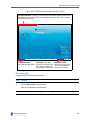
Initial Boot Up of the NVR
Procedure 3-1
Powering up the NVR for the First Time
Step
1
Action
Power up the NVR.
A series of boot messages appear and the system is loaded to the Licence Agreement.
2
When the licence agreement is displayed, select Yes, I Agree to the Licence
Agreement.
3
Click Next.
Set the Password for the Root User account page displays. The next stage of installation
process is to create user accounts.
- End -
Procedure 3-2
Setting Up NVR OS User Accounts
Step
1
Action
In the Password field in the Root User account page of the Installer, enter a password for
the root user account.
Caution
It is extremely important that you will remember this password. If necessary you should write this
password down and store it securely.
2
Re-enter the password in the Confirm Password field.
3
Click Next.
4
If the system does not recognize the password as secure, a message opens. Click Yes to
confirm the use of the weak password and continue, or click No to change the password.
A secure password should contain both upper and lower case letters, numbers and
special characters.
Note
If the passwords entered into the Password and Confirm Password fields do not
match, a message opens. Re-enter the passwords to continue.
5
8
Create an operator user account:
VideoEdge NVR 4.4 Installation and User Manual
Installing the VideoEdge NVR
a
Enter the User’s Full Name.
b
Enter a Username.
Note
A name is suggested depending on the User’s Full Name.
c
Enter a Password.
d
Re-enter the password in the Confirm Password field.
e
Click Next.
Note
1 If the system does not recognize the password as secure, a message opens.
Click Yes to confirm the use of the weak password and continue, or click No to
change the password. A secure password should contain both upper and lower
case letters, numbers and special characters.
2 If the passwords entered into the Password and Confirm Password fields do
not match, a message opens. Re-enter the passwords to continue.
Or
If you do not want to create an operator user account:
a
Leave the User’s Full Name, Username, Password and Confirm Password fields
empty.
b
Click Next.
A message opens stating ‘Empty User Login’ and asking for confirmation to ‘Leave it
empty’.
c
Click Yes.
Note
It is highly recommended to setup an operator account when prompted in addition
to the root user account. The root user account should be used for
troubleshooting and system OS setup only.
6
To continue with the installation and configuration process you need to log in to the NVR
desktop.
- End -
9
Installing the VideoEdge NVR
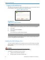
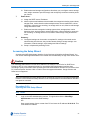
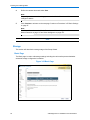
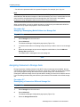
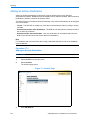
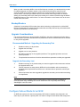
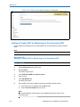
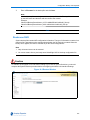
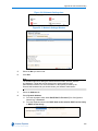
Logging into the NVR Desktop
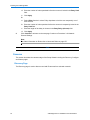
After setting the root password and creation of the administration user you are required to login to
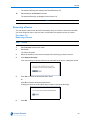
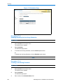
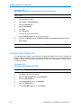
the NVR desktop to continue the installation and configuration process.
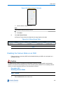
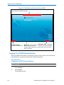
Figure 3-1 NVR Login Screen
Procedure 3-3
Logging into the NVR Desktop
Step
Action
1
When the system boots to the NVR login screen. Enter the Administrator Username.
2
Click Log In.
3
Enter the Administrator Password.
4
Click Log In.
On successful login, the NVR desktop is displayed.
- End -
To complete the installation and configuration process you need to complete the Setup Wizard,
continue to VideoEdge Setup Wizard on page 26.
Installing the NVR Software Only
This section details the installation and configuration process for an NVR software only package.
Before installation you must ensure that the system drive is connected to the SATA 0 location on
the motherboard.
Caution
Any previously configured OS on this system will be removed and over written.
The installation and configuration process consists of:
10
1
(Optional) Verifying the BIOS Configuration
2
Booting the system using the NVR software disk
VideoEdge NVR 4.4 Installation and User Manual
Installing the VideoEdge NVR
3
Using the NVR Wizard to:
a
Configure system information settings
b
Configure disk partitions
c
Verify the boot loader location
d
Complete basic installation
4
A system reboot after basic installation
5
Setting up NVR OS user accounts
6
Logging into the NVR desktop
7
Configuring the NVR using the Setup Wizard
Verify the BIOS Configuration
If required you may need to verify the system BIOS settings before installing the NVR software.
Procedure 3-4
Verify BIOS Configuration
Step
Action
1
Power on the system.
2
While the system is booting up, enter the BIOS menu by pressing the appropriate key.
Usually, the system will inform you of the appropriate key during bootup, but refer to your
user manual if necessary.
3
Confirm that all of the installed devices (e.g. hard drives and CD/DVD drives) are
recognized.
4
Do not adjust the time or date in BIOS. You will set the date and time on the Server’s webbased interface.
5
Confirm that the hyper-threading is enabled if it is available.
6
Confirm that the 1st Boot Device is CD/DVD or Alternative Hard Disk (USB) and 2nd
Boot Device is the hard drive.
7
Select Save and Exit Setup to reboot the system with the above settings.
- End -
Boot your Computer/Server Using the NVR Software CD or USB
To initialize the installation of the NVR, the system must boot from the software CD or USB.
11
Installing the VideoEdge NVR
Procedure 3-5
Boot your Computer/Server Using the NVR Software CD or USB
Step
Action
1
Insert the NVR software CD into the optical drive or insert the NVR Installation USB drive
into one of the available USB ports and restart your computer/server.
2
The NVR boots from the CD or USB drive and the installation options menu opens.
Note
If the NVR does not boot from the disk, please review your computer/server BIOS
option to boot from optical drive or USB. Please check your computer/server
function key to enter boot order (Procedure 3-4 Verify BIOS Configuration on
page 11).
3
From the installations option menu select NVR Live Installer and press Enter.
Note
After approximately 20 seconds the installation will automatically start in this
mode.
A Loading Linux Kernel pop up displays followed by a series of boot messages. This
process may take several minutes.
When the system has finished the initial software installation and restart, the NVR desktop
opens.
Note
The VideoEdge NVR software will install the minimum required Linux Operating
System to run the NVR (The NVR software is installed as an appliance).
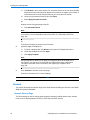
4
Double-click the NVR Installer icon to launch the installation tool.
A Terminal pop-up window displays a loading sequence, and the Live Installer opens,
answer YES to continue.
5
A terminal Window appears asking “Does this system contain a RAID controller with
dedicated cache”. For American Dynamics NVR Hardware and Software Bundles answer
Yes. For software only installations this answer will depend on the hardware you are
providing. Consult with your hardware provider as necessary to provide this answer
6
The next stage of the installation process is to configure the NVR’s system information
settings.
- End -
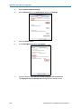
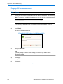
Configure the NVR’s System Information Settings
Using the Installer to configure the system information settings, including the NVR language,
keyboard layout, date and time.
12
VideoEdge NVR 4.4 Installation and User Manual
Installing the VideoEdge NVR
Procedure 3-6
Configuring the NVR System Information Settings
Step
Action
1
In the Welcome page of the Installer, select the required Language from the dropdown.
2
Select the Keyboard Layout from the dropdown.
3
After reading the licence agreement, select the I Agree to the Licence Terms checkbox.
4
Click Next.
The Clock and Time Zone page displays.
5
Select the Region from the dropdown.
6
Select the Time Zone from the dropdown.
The date and time for the selected time zone is displayed.
Note
1 If the time and date settings are not correct you can manually update the
settings by clicking the Change... button and manually entering the current date
and time, or synchronize with the NTP server.
2 For reliable time based playback both the NVR and Client PC need to be
configured as clients of the same NTP server.
7
Ensure the Hardware Clock Set To UTC checkbox is selected.
8
Click Next.
The Suggested Partitioning page displays.
- End -
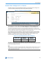
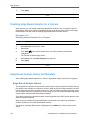
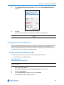
Configure System and Media Storage Partitions
After the system information settings have been configured for the NVR, you can set up the
required storage partitions.
The NVR’s storage consists of two parts; system and media partitions. System partitions are
where the operating system, VideoEdge software and system files are stored. Media partitions are
where video and audio
System partitions must consist of 3 parts:
1
The root partition (/). This is where the operating system, VideoEdge software and
executables are stored.
2
The var partition (/var). This is where configuration and other variable ‘non-video’ files are
stored.
13
Installing the VideoEdge NVR
3
The swap partition (swap). This is the location of the operating system swap area.
Note
On the first media storage drive of the NVR you must create two media partitions. The first partition
created on this drive must be 100GB with the mount point
/var/opt/americandynamics/venvr/clipexport. The second partition must be the remainder of
the media storage drive. You can enter a mount point name as required, for example,
/data/media1. It is recommended that the remaining media drives on the NVR are configured with
1 partition and formatted in the XFS file system type with a mount point name as required, for
example /data/media2.
For American Dynamics NVR Hardware and Software Bundles
If this is the first time the VideoEdge software has been installed on the system, the default system
partitions will already be configured. The system partitions are needed for regular operation of the
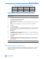
operating system and NVR application. The default system partitions defined are in Table 3-1
below. Each partition size in the table is the required value.
For VideoEdge Software ONLY Installations
If it is the first time the VideoEdge software has been installed in the system, partitions may need
to be deleted and recreated, refer to Configuring System Partitions on a Previously Configured
Device on page 330 and continue to Procedure 3-7 Configuring Media Partitions on the First
Media Drive on the NVR.
Note
When the Linux system starts, it scans the hardware for all system devices. When it finds disks
and partitions it assigns them unique names. Linux does not follow DOS or Windows XP style
partition or drive naming convention. SUSE Linux uses a combination of bus type and
alphanumeric suffixes.
The next part of the naming convention is an alphabetic designation for each physical drive, as an
example the primary drive of a system using SCSI drives would be sda. The secondary physical
SCSI drive naming prefix would be sdb. Tertiary physical drive would be sdc and so on.
As mentioned above the next part of the naming convention is a numerical suffix that denotes the
partition. Each hard drive has a limit of 4 primary partitions. For example the primary SCSI drive of
a system with four partitions would be named as follows: sda1, sda2, sda3 and sda4. As an
example of the naming convention for the secondary drive it would be as follows: sdb1, sdb2, etc
One primary partition per drive can be assigned as an extended partition containing as many
logical partitions as you require.
14
VideoEdge NVR 4.4 Installation and User Manual
Installing the VideoEdge NVR
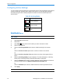
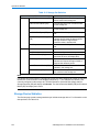
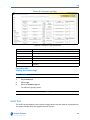
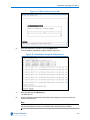
Table 3-1 Default Partitions Required for NVR
Size (GB)
Type
FS Type
Mount Point
16
Linux swap
Swap
swap
476
Linux native
XFS
/var
8
Linux native
Ext3
/
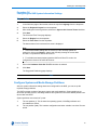
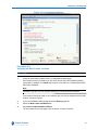
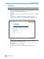
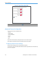
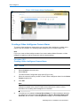
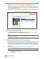
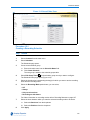
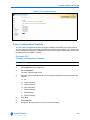
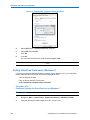
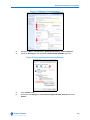
Procedure 3-7
Configuring Media Partitions on the First Media Drive on the NVR
Step
Action
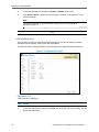
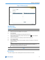
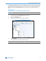
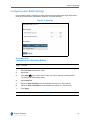
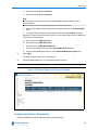
1
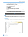
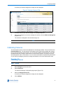
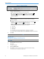
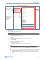
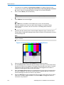
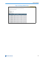
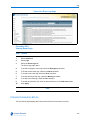
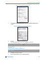
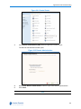
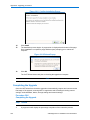
In the Suggested Partioning page of the wizard, click Create Partition Setup.
2
Select Custom Partitioning (for experts).
3
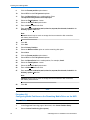
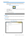
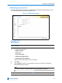
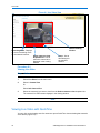
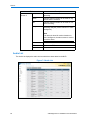
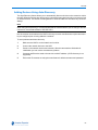
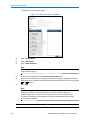
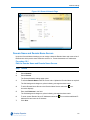
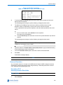
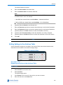
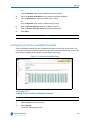
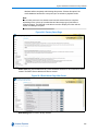
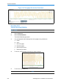
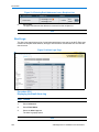
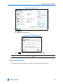
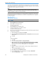
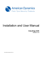
The Expert Partitioner page opens.
Figure 3-2 Expert Partitioner Page
4
Select the first media drive from the system view tree. This is the second physical drive in
the system tree and typically named sdb.
Note
Disks may have existing partitions. If this is the case they should be deleted
before reconfiguring a storage device by adding partitions. Deleting any storage
partitions will destroy any existing data.
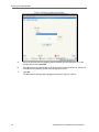
5
Click Add.
6
Select Primary Partition.
7
Select Custom Size and enter 100GB to allocate to the partition.
8
Select Next
15
Installing the VideoEdge NVR
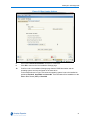
9
Click the Format partition option button.
10
Select XFS from the File System dropdown.
11
Enter the Mount Point for the media partition. Enter
/var/opt/americandynamics/venvr/clipexport
12
Select the Fstab Options... button.
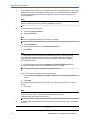
13
Select the Volume Label option button.
14
Enter a Volume Label in the field.
15
Enter rw,noatime,nodiratime,attr2,nobarrier,noquota,allocsize=4m,inode64 in the
Arbitrary option value field.
Note
nobarrier should only be used on storage devices connected to disk controllers
with battery backed cache.
16
Click OK.
17
Click Add.
18
Select Primary Partition.
19
Select the Maximum Size option to use the remaining disk space.
20
Select Next
21
Click the Format partition option button.
22
Select XFS from the File System dropdown.
23
Enter the Mount Point for the media partition, for example, /data1.
24
Select the Fstab Options... button.
25
Select the Volume Label option button.
26
Enter a Volume Label in the field.
27
Enter rw,noatime,nodiratime,attr2,nobarrier,noquota,allocsize=4m,inode64 in the
Arbitrary option value field.
Note
nobarrier should only be used on storage devices connected to disk controllers
with battery backed cache.
28
Click OK.
- End -
Procedure 3-8
Configuring Media Partitions on the Remaining Media Drives on the NVR
Step
16
Action
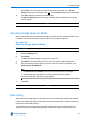
1
In the Suggested Partioning page of the wizard, click Create Partition Setup.
2
Select Custom Partitioning (for experts).
VideoEdge NVR 4.4 Installation and User Manual
Installing the VideoEdge NVR
The Expert Partitioner page opens.
3
Select the disk on which you want to create the media partition from the system view tree.
This can be either the hard disk on the NVR itself or on separate RAID or FRS storage
devices. If a hard disk on the NVR itself this would be the third physical drive in the system
tree and typically named sdc.
Note
Disks may have existing partitions. If this is the case they should be deleted
before reconfiguring a storage device by adding partitions. Deleting any storage
partitions will destroy any existing data.
4
Click Add.
5
Select either Primary Partition or Extended Partition.
Note
A Primary Partition contains one file system. Up to four primary partitions can be
created on a single hard drive.
An Extended Partition is a primary partition that has been divided up into logical
partitions as a means of creating more partitions than the four that would
otherwise be possible. Only one primary partition can be used as an extended
partition, and it can be created from any of the primary partitions. The logical
partitions do not need to fill the entire extended partition.
6
Enter the required partition size. You can select the Maximum Size option to use the
remaining disk space, or select Custom Size and enter the amount of disk space (GB) you
want to allocate to the partition.
Or
Choose an allocated region on the disk for the partition by entering a Start Cylinder and
End Cylinder.
Note
In order to use a disk partition for storage it must meet the minimum storage
capacity requirements, 10GB.
7
Select Next
8
If you are creating an extended partition, go to Step 18, otherwise continue to Step 10.
9
Click the Format partition option button.
10
Select XFS from the File System dropdown.
11
Enter the Mount Point for the media partition, for example, /data/media1.
12
Select the Fstab Options... button.
13
Select the Volume Label option button.
14
Enter a Volume Label in the field.
17
Installing the VideoEdge NVR
15
Enter rw,noatime,nodiratime,attr2,nobarrier,noquota,allocsize=4m,inode64 in the
Arbitrary option value field.
Note
nobarrier should only be used on storage devices connected to disk controllers
with battery backed cache.
16
Click OK.
17
Click Finish.
18
Repeat Steps 3 to 17 to create additional media storage partitions.
19
Once the required number of media partitions are created click Accept.
A summary of the partitions to be created are displayed. If you want to edit any of the
partitions click Edit Partition Setup and make the changes as required.
20
Click Next.
A summary of the partition layout to be created is displayed.
21
Click Install and click Install again to confirm.
The Live Installation Settings page is displayed.
22
Continue to Verify the Boot Loader location.
- End -
Verify the Boot Loader location
The boot loader must be on the same disk where the operating system software will be installed. If
the boot loader is not on the same disk the system software is located system boot problems may
occur.
Before confirming installation you can compare the location of the boot loader and the location
chosen for system installation and partitioning.
In Figure 3-3 Live Installation Settings below the installer has chosen to use the disk /dev/sdb for
the partitioning proposal but the disk on which to install the boot loader is /dev/sda.
18
VideoEdge NVR 4.4 Installation and User Manual
Installing the VideoEdge NVR
Figure 3-3 Live Installation Settings
Procedure 3-9
Verifying the Boot Loader Location
Step
1
Action
Check the boot loader location on the Live Installation Settings page.
If the location for the boot loader is on the same disk as where the software operating
system will be installed, click Install and continue to Procedure 3-10 Rebooting the NVR
After Basic Installation.
Note
Installation may take up to ten minutes depending on computer/server hardware.
If the location of the boot loader is on a different disk you need to change the boot loader
location. Continue to Step 2.
2
In the Live Installation Settings page select the Booting hyperlink.
3
Select the Boot Loader Installation tab.
4
Select Boot Loader Installation Details.
The boot loader Device map page opens as shown in Figure 3-4 below.
19
Installing the VideoEdge NVR
Figure 3-4 Boot Loader Device Map
5
Select the disk that has the operating system installed from the Disk Order list. In the
example shown this is /dev/sdb.
6
Click Up to move the selected disk to a higher position in the Disk Order list. Continue to
click Up until the operating system disk is at the top of the list.
7
Click OK.
The Boot Loader settings page is displayed as shown in Figure 3-5 below.
20
VideoEdge NVR 4.4 Installation and User Manual
Installing the VideoEdge NVR
Figure 3-5 Boot Loader Settings
8
Ensure the Custom Boot Partition checkbox is unchecked.
9
Click OK to return to the Live Installation Settings page.
10
Confirm on the Live Installation Settings page that the GRUB boot loader and the
operating system are now configured on the same drive.
In the example shown in Figure 3-6 below the operating system is set to be installed on
partitions /dev/sbd1, /dev/sdb2/ and /dev/sdb3. The boot loader will be installed on to the
Master Boot Record (MBR) of /dev/sdb.
21
Installing the VideoEdge NVR
Figure 3-6 Live Installation Settings
11
Click Install.
Note
Installation may take up to ten minutes depending on computer/server hardware.
12
Continue to System Reboot After Basic Installation.
- End -
System Reboot After Basic Installation
After basic installation is complete the NVR must be restarted to progress to the next stage of the
installation process.
Note
If you forget to remove the software CD or USB from the computer/server you will be given the
option to select ‘Boot from Hard Disk’.
Procedure 3-10
Rebooting the NVR After Basic Installation
Step
1
22
Action
After basic installation is complete a Finished Basic Installation dialog appears. Click OK.
VideoEdge NVR 4.4 Installation and User Manual
Installing the VideoEdge NVR
The Live Installer closes and the Terminal Window opens.
2
Use the keyboard to enter Y followed by the [Enter], in the Terminal Window.
3
Ensure the BIOS splash screen is displayed. Remove the disk or detach the USB drive.
The NVR reboots and the installation options menu opens.
Caution
It is recommended to remove the disk or USB before the BIOS splash screen is displayed.
4
(Optional) If you do not remove the disk/USB, use the keyboard to select Boot from Hard
Disk and press the [Enter].
5
After the system has booted the licence agreement is displayed, select Yes, I Agree to
the Licence Agreement to continue with the VideoEdge software installation.
6
Click Next.
The Password for the Root User account page displays. The next stage of installation
process is to create user accounts.
- End -
Set Up NVR OS User Accounts
The next stage of the installation and configuration process is to set a password for the root user
account. You also must create an operator user account and password. These accounts will be
used for logging into the NVR operating system to access the NVR desktop.
Note
It is highly recommended to setup an operator account when prompted in addition to the root user
account. The root user account should be used for troubleshooting and system OS setup only.
Procedure 3-11
Setting Up NVR OS User Accounts
Step
1
Action
In the Password for the Root User account page of the Installer, enter a password for the
root user.
Caution
It is extremely important that you will remember this password. If necessary you should write this
password down and store it securely.
2
Re-enter the password in the Confirm Password field.
3
Click Next.
23
Installing the VideoEdge NVR
4
If the system does not recognize the password as secure, a message opens. Click Yes to
confirm the use of the weak password and continue, or click No to change the password.
A secure password should contain both upper and lower case letters, numbers and
special characters.
Note
If the passwords entered into the Password and Confirm Password fields do not
match, a message opens. Re-enter the passwords to continue.
5
Create an operator user account:
a
Enter the User’s Full Name.
b
Enter a Username.
Note
A name is suggested depending on the User’s Full Name.
c
Enter a Password.
d
Re-enter the password in the Confirm Password field.
e
Click Next.
Note
1 If the system does not recognize the password as secure, a message opens.
Click Yes to use the password and continue, or click No to change the password.
A secure password should contain both upper and lower case letters, numbers
and special characters.
2 If the passwords entered into the Password and Confirm Password fields do
not match, a message opens. Re-enter the passwords to continue.
Or
If you do not want to create an operator user account:
a
Leave the User’s Full Name, Username, Password and Confirm Password fields
empty.
b
Click Next.
A message opens stating ‘Empty User Login’ and asking for confirmation to ‘Leave it
empty’.
c
Click Yes.
Note
It is highly recommended to setup an operator account when prompted in addition
to the root user account. The root user account should be used for
troubleshooting and system OS setup only.
6
To continue with the installation and configuration process you need to log in to the NVR
desktop.
- End -
24
VideoEdge NVR 4.4 Installation and User Manual
Installing the VideoEdge NVR
Log into the NVR Desktop
After setting up user accounts, to continue the installation and configuration process you need to
log into the NVR desktop.
Figure 3-7 NVR Login Screen
Procedure 3-12
Logging into the NVR Desktop
Step
Action
1
When the system boots to the NVR login screen. Enter your operator Username.
2
Click Log In.
3
Enter your Password.
4
Click Log In.
On successful login, the NVR desktop is displayed.
- End -
25
Installing the VideoEdge NVR
VideoEdge Setup Wizard
Once the NVR has been installed you need to configure the NVR settings via the Setup Wizard.
This can be accessed using the VideoEdge Administrator icon on the NVR desktop or via a
remote client. On the first time accessing the NVR user interface after installation you will be
automatically be directed to the Setup Wizard.
Note
If you exit the Setup Wizard prior to completing all the steps, the wizard will save your progress
and automatically return to the last page viewed of the Setup Wizard.
The Welcome page is the first page of the Setup Wizard. The purpose of the wizard is to aid you in
the final stages of the NVR’s installation and configuration. On completion your NVR will be
operational.
The Setup Wizard provides the option to configure the following:
1
2
3
Preparation a
Selected Language.
b
Application of a permanent license, generation of a Host ID, application of a template
file (this is pre-defined settings for the NVR)
Network a
Edit the general network settings including domain name, domain name servers,
default gateway, RTSP port, NTP status and NTP servers.
b
Edit the LAN settings for each NIC including IP address allocation, LAN IP address,
subnet mask and IP broadcast, the MAC address for each NIC can also be viewed.
c
Edit the DHCP settings for each NIC including, DHCP status, IP address start range,
IP address end range, subnet and netmask.
d
Edit the WAN settings including the WAN IP address, HTTP port, secure HTTP port,
streaming configured port.
e
Edit the Dynamic Bandwidth settings including Bandwidth Priority, Traffic Smoothing,
WAN bitrate cap and LAN bitrate cap and Transcode Limit.
Failover
a
4
5
6
System a
Configure the general system information including NVR hostname, location, current
date/time.
b
Configure user roles.
Cameras a
Add cameras using Discovery.
b
Add cameras manually.
c
Configure camera alarms.
Storage a
26
Configure the NVR as a Failover server (optional).
Assign custom percentage of storage as the Vault Media Quota. This is the
percentage of media storage that is allocated to protected media.
VideoEdge NVR 4.4 Installation and User Manual
Installing the VideoEdge NVR
b
7
8
Enable advanced storage configuration; this allows you to configure custom storage
sets, assign cameras to specific storage sets and specify maximum retention period
per camera.
Email Alerts a
Assign the SMTP server IP address.
b
Add a recipient email address with selectable alert categories including system alerts,
storage alerts, motion detection alerts analytics alerts, camera malfunction, reboot
notification, camera(s) not recording, no storage active on unit, failed to read storage
config and failover event.
c
Enable and test alert categories including system alerts, storage alerts, motion
detection alerts, analytics alerts, camera malfunction, reboot notification, camera(s)
not recording, no storage active on unit, failed to read storage config and failover
event.
Summary a
Configured settings can be saved to a template file, settings to be saved can be
selected using check boxes, they include camera settings, storage settings, user
information, network settings, email settings and failover settings.
b
Setup is completed by selecting Finish.
Accessing the Setup Wizard
Accessing the NVR Administrator Interface for the first time will initialize the Setup Wizard. You
can use the VideoEdge Administrator icon located on the NVR desktop or login via a remote client.
Caution
The VideoEdge Administrator icon has been added for convenience. 10.0 Firefox for SUSE Linux
Enterprise SLE-11 is the supported browser for use with the NVR Administrator Interface when
accessing it locally on the NVR. When Accessing the NVR Administration Interface from a remote client
PC, Internet Explorer Versions 8 & 9 or Firefox 10 are the supported browsers. Google Chrome and
Safari are not supported.
Note
After initial installation the Setup Wizard can be accessed at any time from the NVR Administration
Interface. Once initiated the Setup Wizard must be completed before the Administration Interface
can again be accessed.
Procedure 3-13
Opening the NVR Setup Wizard
Step
1
Action
Login to the NVR Administration interface. To login double-click the VideoEdge
Administrator icon on the SUSE desktop.
OR
Open a web browser from a remote client PC and enter the IP address 10.10.10.10. This
is the default IP address.
27
Installing the VideoEdge NVR
The browser opens and automatically connects to the Setup Wizard (Setup Wizard
displays after installation when the Administration Interface is accessed until the wizard
has been completed).
Figure 3-8 VideoEdge Administrator Icon
2
You will be prompted to enter a Username and Password. Enter the following credentials:
Username: admin
Password: VIDEO!edge23
3
Click OK.
The wizard’s Welcome page opens.
- End -
Preparation
This section describes the preparation stage of the Setup Wizard including the Welcome, Setup
and Failover pages.
Welcome Page
The Welcome page is the first page of the Setup Wizard and allows you to select the language in
which the Administration Interface is displayed, to advance to the next page click Start.
Figure 3-9 Welcome Page
28
VideoEdge NVR 4.4 Installation and User Manual
Installing the VideoEdge NVR
Procedure 3-14
Selecting the Language
Step
1
Action
Select the required language from the Choose Language dropdown.
A dialog box opens stating ‘Changing the language setting will require a web server
restart. Click OK to restart, or Cancel to abort.’
2
Click OK.
The Welcome page refreshes.
3
Click Next.
- End -
Setup Page
The Setup page provides an interface to apply a licence or generate a host ID. There also is an
option to apply template settings. The host ID is required for upgrade and new installations.
Figure 3-10 Setup Page
Procedure 3-15
Configuring the Setup Page
Step
Action
1
Apply your saved licence file:
29
Installing the VideoEdge NVR
a
Click Browse in the License section. For convenience there is an icon on the desktop
with direct access to the American Dynamics.net web site to register your license. In
most instances the license will be emailed to you in less than one minute.
b
Locate your permanent license file and click Open.
c
Select Apply Permanent License.
Or
Request a licence by generating a Host ID
a
Click Generate Host ID.
Note
Your NVR host ID should be quoted to American Dynamics if you wish to apply for
your license. For more information refer to Procedure 15-1 Generate a Host ID on
page 166.
Or
To utilize the 60 day trial continue to the next step.
2
(Optional) Apply a Template file.
a
To import a template file, click Browse in the Upload a Template file section
b
Locate the template file and click Open.
c
Click Apply Template.
Note
Using a template file allows you to apply pre-configured values to the NVR, this is
very useful if you want to set up more than one NVR with the same configuration.
For further information refer to Procedure 19-4 Importing a Template File on
page 230.
3
Click Continue to advance to the next page.
Continue to Procedure 3-21 Failover Settings.
- End -
Network
This section describes the network stage of the Setup Wizard including the General, LAN, DHCP,
WAN and Dynamic Bandwidth.
Network General Page
The General page is used to edit the general network settings including domain name, domain
name servers, default gateway, RTSP port, NTP status and NTP servers.
30
VideoEdge NVR 4.4 Installation and User Manual
Installing the VideoEdge NVR
Figure 3-11 Network General Page
Procedure 3-16
Network General Settings
Step
1
Action
To edit the following fields:
• Domain Name
• Default Gateway
• RTSP Port
Select the current value. Edit the value as required.
2
Click Save.
3
To edit the following fields:
• Domain Name Servers
• NTP Servers
a
Select the
icon.
A text box displays
b
Enter the Server addresses in the text box.
c
Click Save.
Caution
In order to provide reliable playback both the NVR and victor client must be NTP clients of the same NTP
server.
31
Installing the VideoEdge NVR
4
To edit the NTP Status click either the Enable or Disable option button.
5
Click Save/Continue to advance to the next page. Continue to Procedure 3-17 LAN
Interface Settings.
Note
For further information on general network settings refer to General Network
Settings on page 172.
- End -
LAN Interface Page
The LAN page is used to edit the LAN interface settings for each NIC including IP address
allocation, LAN IP address, subnet mask and IP broadcast.
The NVR can have multiple active NICs. This allows the use of dedicated camera networks.
Figure 3-12 LAN Interface Page
Procedure 3-17
LAN Interface Settings
32
Step
Action
1
To edit the LAN Interface settings, select Edit next to the NIC you want to modify. You can
edit the following fields:
VideoEdge NVR 4.4 Installation and User Manual
Installing the VideoEdge NVR
• IP Address Allocation
Note
To open the NVR Administration Interface the IP address of one of the NICs must
be known, if all the IP addresses are dynamic they will vary in value. It is
recommended that a NIC is configured with a static IP address and subnet mask
for this reason.
• LAN IP address
• Subnet Mask
Note
The Subnet Mask is defined by three classes of IP Address A, B and C which will
determine its value. They are as follows:
• Class A - First Octet Decimal Range 1-126, Subnet Mask Value 255.0.0.0
• Class B - First Octet Decimal Range 128-191, Subnet Mask Value 255.255.0.0
• Class C - First Octet Decimal Range 192-223, Subnet Mask Value
255.255.255.0
Class A addresses 127.0.0.0 to 127.255.255.255 cannot be used and are reserved for
loopback and diagnostic functions.
• IP broadcast (required)
2
Edit the setting as required and click Save.
3
Click Continue to advance to the next page. Continue to Procedure 3-19 WAN Settings.
Note
For further information on LAN interface settings refer to Procedure 16-8 Editing
the LAN Interface Values on page 178.
- End -
DHCP Server Page (Optional)
The DHCP Server page is used to edit the DHCP server settings for each NIC including the DHCP
status, start range, end range, subnet and netmask. Each NIC can be used to host a DHCP server
for the LAN it is attached to.
If a NIC has been designated a Dynamic IP address it will not be available for editing on this page.
The DHCP Status page allows you to view all active devices which have been assigned a dynamic
IP address by the NVR.
33
Installing the VideoEdge NVR
Figure 3-13 DHCP Server Page
Procedure 3-18
DHCP Server Settings
Step
Action
1
To edit the following fields:
• DHCP Status
• Start Range
• End Range
• Subnet
• Netmask
for each NIC select Edit next to the setting.
2
Edit the setting and click OK.
3
Click Continue to advance to the next page.
Note
For further information on DHCP Server settings refer to Procedure 16-9 Editing
the DHCP Server Settings on page 180.
- End -
34
VideoEdge NVR 4.4 Installation and User Manual
Installing the VideoEdge NVR
WAN Settings Page (Optional)
The WAN Settings page is used to edit the WAN settings including the WAN IP address, HTTP
port, secure HTTP port and streaming configured port.
Figure 3-14 WAN Settings Page
Procedure 3-19
WAN Settings
Step
1
Action
To edit the following fields:
• WAN IP address
• HTTP Port
• Secure HTTP Port
• Streaming Configured Port
• Allowed Private IP Addresses
Select the current value. Edit the value as required.
2
Click Save.
3
Click Continue to advance to the next page. Continue to Procedure 3-20 Dynamic
Bandwidth Settings on page 36.
Note
For further information on WAN settings refer to WAN Settings on page 181.
- End -
35
Installing the VideoEdge NVR
Dynamic Bandwidth Page
The Dynamic Bandwidth page is used to edit the Bandwidth Throttling settings including
Bandwidth Priority, Traffic smoothing, WAN and LAN bitrate caps and Transcode Limit. The
Dynamic Bandwidth page is also used to set the Archive Bitrate Cap which prevents video being
transferred from the NVR exceeding a definable bitrate.
Bandwidth throttling options that are available include:
• Traffic Smoothing - When enabled allows the ability to pace the traffic leaving the NVR to
individual clients without incurring framedrop or transcode. This smooths bursts of traffic which
may cause issues for some consumer grade NICs consuming this data.
• Preserve Framerate - When enabled any overloaded network or set caps on the NVR/client will
allow the NVR to adapt the streams accordingly by reducing the bitrate by transcoding a stream
to H.264, lower bitrate and possibly lower resolution. If all transcode resources are used, best
effort streaming will occur.
• Preserve Resolution - When enabled any overloaded network or set caps on the NVR/client will
allow the NVR to adapt the streams accordingly by reducing the stream output using framedrop.
If framedrop should fail or doesn’t occur, then best effort streaming will occur.
• Allow any throttle type - When enabled any overloaded network or set caps on the NVR/client
will allow the NVR to adapt the streams accordingly by either transcoding, transcoding and
framedropping on the transcoded stream and if all the transcode resources are used, framedrop
will be invoked only. If any of the above should fail, then best effort streaming will occur.
Figure 3-15 Dynamic Bandwidth Page.
Procedure 3-20
Dynamic Bandwidth Settings
Step
1
36
Action
To edit the following fields:
VideoEdge NVR 4.4 Installation and User Manual
Installing the VideoEdge NVR
• Bandwidth Priority
Click the required option button.
Which of the available fields display will depend on which Bandwidth Priority option is
enabled.
2
Click Save.
3
To edit the Traffic Smoothing values select the current values. Update the values as
required.
4
Click Save.
5
To edit the following fields:
• WAN Bitrate Cap
• LAN Bitrate Cap
Select the required value from the dropdown.
Or
a
To use a custom value, select Custom from the dropdown.
The custom entry field displays.
b
To edit the bitrate cap value select the current value. Update the value as required.
c
Enter the desired bitrate cap value in the field.
Note
The custom value must be entered in kbps. For example to enter a value of
5.5Mbps you would type a value of 5500.
6
To edit the Transcode Limit select the required value from the dropdown.
7
Click Save.
8
To edit the Archive Bitrate Cap, select the required value from the dropdown.
Or
a
To use a custom value, select Custom from the dropdown.
The custom entry field displays.
b
To edit the Archive Bitrate Cap value select the current value. Update the value as
required.
c
Enter the desired bitrate cap value in the field.
Note
The custom value must be entered in kbps. For example to enter a value of
5.5Mbps you would type a value of 5500.
37
Installing the VideoEdge NVR
9
Click Continue to advance to the next page. Continue to Procedure 3-18 DHCP Server
Settings on page 34.
Note
For further information on Dynamic Bandwidth settings refer to Bandwidth Priority
on page 186.
- End -
Failover Page (Optional)
The Failover page is used to enable the NVR to act as a failover server for one or more NVRs on
the network. If Failover is not being implemented continue to Procedure 3-22 System Info Settings.
Note
When configuring failover ensure that all NVRs have their time synchronized to a NTP server or to
your secondary NVR by enabling NTP in the General Network settings. For further information
refer to General Network Settings on page 172.
Figure 3-16 Failover Page
Procedure 3-21
Failover Settings
Step
1
Action
Select Enable this NVR as a Failover Server if required.
The NVR Failover page opens.
38
VideoEdge NVR 4.4 Installation and User Manual
Installing the VideoEdge NVR
2
Configure the Failover settings as required.
3
Select Continue to advance to the next page. Continue to Procedure 3-22 System Info
Settings.
Note
For further information on configuring an NVR as a Failover server refer to NVR
Failover on page 211.
- End -
System
This section describes the system stage of the Setup Wizard including the General and Roles
pages.
System Info Page
The System Info page is used to edit the NVR hostname, location, current date and current time.
You can also download the NVR’s public key which is used for verifying the integrity of exported
clips.
Figure 3-17 System Info Page
Procedure 3-22
System Info Settings
Step
Action
1
To edit the following fields:
39
Installing the VideoEdge NVR
• Hostname
• Current Date/Time
Select the current value. Edit the value as required.
2
Click Save.
3
To download the public key, click Download public key.
A Windows dialog box opens.
4
Click Save.
The public key is saved as a PEM File and can be viewed using Windows Notepad.
5
Click Continue to advance to the next page. Continue to Procedure 3-23 Roles Settings.
Note
For further information on General System settings refer to General System
Information on page 153.
- End -
Users and Roles Pages
The Users and Roles pages are used to create, edit and delete user account credentials for
accessing the Administration Interface and the VideoEdge Client.
There are five default user role accounts; admin, operator, viewer1, viewer2 and viewer3. The
names of each of these default role accounts cannot be changed, however, you can change the
password associated with the account.
The default credentials of each account are:
ID: admin
Password: VIDEO!edge23
ID: operator
Password: VideoEdge
ID: viewer1
Password: ViewerOne
ID: viewer2
Password: ViewerTwo
ID: viewer3
Password: ViewerThree
You can create new user accounts and assign a bespoke username and password for each
account using the Add New User functionality. Each new account created must have a role
assigned. The role determines the user privileges for the account.
Each role can have a bespoke lockout policy applied to either lock the user permanently or
temporarily out of their account should they incorrectly enter their password a set number of
times.
For further information on role and account privileges refer to Users and Roles on page 157.
40
VideoEdge NVR 4.4 Installation and User Manual
Installing the VideoEdge NVR
Figure 3-18 Roles Page
Procedure 3-23
Roles Settings
Step
1
2
3
Action
To change the password for a default account:
a
Select Edit next to the appropriate username.
b
Enter the default password for the account into the Current Password field.
c
Enter the new password into the New Password field.
d
Enter the new password into the Confirm Password field.
e
Click Apply.
To create a new user account:
a
Click Add New User.
b
Enter the user name in the Username field.
c
Enter the password in the New Password field.
d
Enter the password in the Confirm Password field.
e
Select the Role from the dropdown to determine the account privileges.
f
Click Apply.
To apply a Lockout policy:
a
Select the Roles tab.
b
Select Edit next to the appropriate role.
c
Select Lockout from the Lockout Policy dropdown to lock the user permanently out
of their account (requires an admin or support user to unlock)
41
Installing the VideoEdge NVR
d
Enter the number of retries permitted before the account is locked in the Retry Limit
field.
e
Click Apply.
Or
4
a
Select Delay from the Lockout Policy dropdown to lock the user temporarily out of
their account.
b
Enter the number of retries permitted before the account is temporarily locked in the
Retry Limit field.
c
Enter the length of the delay in minutes in the Retry Delay (minutes) field.
d
Click Apply.
Click Continue to advance to the next page. Continue to Procedure 3-16 Network
General Settings.
Note
For further information on Roles refer to Users and Roles on page 157.
- End -
Cameras
This section describes the cameras stage of the Setup Wizard including the Discovery, Configure
and Alarms pages.
Discovery Page
The Discovery page is used to discover and add IP cameras from selected networks.
42
VideoEdge NVR 4.4 Installation and User Manual
Installing the VideoEdge NVR
Figure 3-19 Discovery Page
Procedure 3-24
Discovery Settings
Step
Action
1
Select the camera network NIC from the dropdown.
2
Select Discover.
Discovered devices will display in the Discovered Device List.
3
Select checkbox for cameras you want to add. Use the arrow
cameras to the NVR list.
to move selected
4
Select the checkbox for the cameras you want to add in the NVR list.
5
Select Import to NVR.
6
Select Continue to advance to the next page. Continue to Procedure 3-25 Video List
Settings on page 44.
Note
For further information on Camera and Device Discovery refer to Procedure 7-4
Adding Devices using Auto-Discovery on page 88.
- End -
Video List Page
The Video List page is used to manually add IP cameras and devices to the NVR.
43
Installing the VideoEdge NVR
Figure 3-20 Video List Page
Procedure 3-25
Video List Settings
Step
1
Action
Select Add New Camera.
Add Camera Window opens.
2
Enter camera name in the Camera Name textbox.
3
Enter the cameras IP address in the Internal IP Address textbox.
4
Select the Password Group from the dropdown list.
Note
The Password Group will usually be default. The NVR will use the manufacturers
default password to connect to the camera. However, if you have changed the
password for this camera, you need to assign the camera to the appropriate
password group, or create a new password group. For further information on
password groups refer to Camera Password Groups on page 149.
44
5
(Optional) If multiple storage sets are defined, select the Storage Set from the dropdown
list.
6
Select Apply.
VideoEdge NVR 4.4 Installation and User Manual
Installing the VideoEdge NVR
7
Select Continue to advance to the next page. Continue to Procedure 3-26 Alarms
Settings on page 45.
Note
For further information on adding cameras manually refer to Procedure 7-3
Manually Adding an IP Device on page 86. To change settings such as resolution,
codec (compression), framerate, etc refer to Procedure 8-1 Editing Basic Video
Settings via the Device List on page 93
- End -
Alarms Page
The Alarms page is used to configure Video Intelligence and Motion Detection alarms for individual
cameras. Motion Detection or Video Intelligence must be enabled on each camera for which you
wish to configure alarms.
Figure 3-21 Alarms Page
Procedure 3-26
Alarms Settings
Step
Action
1
Select the camera you want to add an alarm to from the Select Camera dropdown menu.
2
Select the Current Record Status for the camera.
3
Select Add.
45
Installing the VideoEdge NVR
4
Define the camera alarm and select Save.
Note
Depending on the camera’s settings you can select Motion Detection or Video
Intelligence alarms.
5
Click Continue to advance to the next page. Continue to Procedure 3-27 Basic Settings
on page 47.
Note
For further information on the Motion Detection and Video Intelligence refer to
Motion Detection on page 115 and Video Intelligence on page 125.
- End -
Storage
This section will describe the storage stage of the Setup Wizard.
Basic Page
The Basic page is used to edit storage settings including the vault media quota and whether
advanced storage configuration is enabled.
Figure 3-22 Basic Page
46
VideoEdge NVR 4.4 Installation and User Manual
Installing the VideoEdge NVR
Procedure 3-27
Basic Settings
Step
Action
1
To edit the Vault Media Quota select Edit, then enter the desired percentage of storage to
be allocated as the Vault Media Quota in the text box.
2
Click Save.
3
To add drives to storage, select the check boxes for each desired drive, then click Add to
Storage.
4
(Optional) Select to the Enable Advanced Storage configuration option button.
Two additional steps are added to the wizard; Storage Sets and Assign Cameras.
Figure 3-23 Basic Page with Advanced Storage Configuration Enabled
Note
Enabling advanced storage allows you to create storage sets and to assign media
folders of cameras to the created storage sets.
5
Click Continue to advance to the next page.
If advanced storage configuration is enabled continue to Storage Sets Page.
Or
47
Installing the VideoEdge NVR
If advanced storage configuration is disabled continue to Procedure 3-30 Email Alerts
Settings.
Note
For further information on assigning cameras manually to storage sets refer to
Procedure 5-7 Reassigning a Camera to a Different Storage Set on page 70.
- End -
Storage Sets Page
The Storage Sets page allows you to create custom storage sets from the media folders which
were created during the Configuring Storage Partitions stage of the installation.
Figure 3-24 Storage Sets Page
Procedure 3-28
Storage Set Settings
Step
48
Action
1
Click Add Storage Set to create a new storage set.
2
Use the checkboxes to select media folders.
3
Use the Move to Storage Set dropdown to select the storage set you wish to move the
media folders to.
VideoEdge NVR 4.4 Installation and User Manual
Installing the VideoEdge NVR
4
Click Continue to advance to the next page. Continue to Procedure 3-29 Assign Cameras
Settings
Note
For further information on assigning cameras to storage sets refer to Media Folder
Assignment for Storage Sets on page 69.
- End -
Assign Cameras Page
The Assign Cameras page allows you to assign cameras to different storage sets to best suit your
storage specifications. You can also calibrate each camera to calculate its data transfer rate which
you can use to determine the best storage set to assign it to.
Figure 3-25 Assign Cameras Page
Procedure 3-29
Assign Cameras Settings
Step
Action
1
Select the Assign Cameras tab.
2
Use the checkboxes to select the cameras you want to calibrate.
3
Click Calibrate.
Calibration will allow the cameras to record for 2 minutes, click OK when done.
4
Use the Move to Storage Set dropdown to select the storage set you want to move the
camera to.
49
Installing the VideoEdge NVR
5
Click Continue to advance to the next page. Continue to Procedure 3-30 Email Alerts
Settings on page 50
Note
For further information on assigning media folders to storage sets refer to
Assigning Cameras to Storage Sets on page 70.
- End -
Email Alerts
This section describes the email alerts stage of the Setup Wizard.
Email Alerts Page
The Email Alerts page is used to assign a SMTP server address, add recipients to receive email
alerts, edit the alerts received by each recipient and enable/disable alert types.
Figure 3-26 Email Alerts Page
Procedure 3-30
Email Alerts Settings
Step
50
Action
1
Enter the IP address in the SMTP Server IP text box.
2
Click Add/Update Alert Recipient.
VideoEdge NVR 4.4 Installation and User Manual
Installing the VideoEdge NVR
3
Click the New Recipient Email Address option button and enter a recipient email
address in the field and/or click the Use Recipient Email Address option button and
select an already entered address from the dropdown.
4
Select the Alert Categories to be assigned to the address(es) using the check boxes.
5
Click Save.
6
Select the Alert Category check boxes.
7
Click Enable Alert(s).
8
Click Test next to an alert category to send a test email alert.
9
Click Continue to advance to the next page. Continue to Procedure 3-31 Completing the
NVR Setup.
Note
For further information on email alerts refer to Email Alerts on page 259.
- End -
Finish
This section allows you to save a template of the current NVR settings. These can then be used if
the NVR is reinstalled or used to quickly configure another NVR with these settings.
Summary Page
The Summary page is used to save a settings template file prior to finishing the setup process. A
saved template can be used in the future to set up an NVR with these settings.
Figure 3-27 Summary Page
51
Installing the VideoEdge NVR
Procedure 3-31
Completing the NVR Setup
Step
Action
1
Select the checkboxes for the template settings you want to save.
2
Click Save.
3
Select Save File and click Browse.
4
Navigate to the folder where you want to save the template.
5
Enter a File name for the template and click Save.
6
Click Finish to complete the Setup Wizard or click Previous to go back.
Note
For further information on templates refer to Configuration Backup and Templates
on page 225.
- End -
After you have finished installation and completed all your NVR configuration it is recommended
that you create a backup of your NVR. Refer to Create a Configuration Backup File on page 226.
52
VideoEdge NVR 4.4 Installation and User Manual
Using the NVR Administration Interface
Overview
The NVR Administration Interface allows users to interact with the NVR. This provides information
about the server and allows you to modify the server’s settings. The NVR interface is accessible
via a web browser, through victor unified client or locally on your hardware. All pages on the web
client are static. You must refresh your browser to keep all information current.
To access the NVR Administration Interface from a remote workstation, you must know its IP
address and have a User name and Password combination that is valid for the NVR.
A remote workstation logging into the NVR using the Administration Interface must have Java 6 or
above installed. If the workstation is connected to the Internet, but does not have Java installed,
you must download Java from its website http://www.java.com. You must also enable javascript on
your browser.
To access the NVR through victor unified client, you must add the NVR Recorder to your recorders
in the device list in victor client. For information on how to add the NVR recorder to victor refer to
Setting Up Recorder Devices in the victor Configuration and User Guide.
This chapter explains how to log into the NVR Administration Web Interface, access the NVR
Administration Interface via victor unified client and provides an overview of the user interface.
Logging into the NVR Administrator Interface via a Web Browser
To access the NVR Administrator Interface you must log in. There are two user accounts, System
Administrator and Operator.
If you log in using a System Administrator account you will have access to configure and edit all
settings of the NVR. If you log in using a Operator account, you do not have permissions to edit
any of the settings, you can only view the current settings and view live video.
Procedure 4-1
Logging into the NVR Administrator Interface via a Web Browser
Step
1
Action
Launch your web browser and enter the NVR IP address into the URL field.
53
Using the NVR Administration Interface
Enter http://NVR_Server_IP_Address, where NVR_Server_IP_Address is the IP
address of the machine running the NVR software, for example, http://192.187.100.21
2
The NVR login dialog box opens. Enter your User name and Password.
User name: admin
Default Password: VIDEO!edge23
Or
User name: operator
Default Password: VideoEdge
Note
1 You are asked to login/authenticate when you:
• First log on to the NVR Administrator Interface.
• Are already logged on and your user access is changed.
2 If you have changed the account passwords, use these in place of the default
password.
Figure 4-1 NVR Login Dialog
3
Click OK.
The Administration interface for the NVR opens (Figure 4-3).
- End -
victor NVR Administration Interface
To access the victor NVR Administration interface you must have the NVR added as a recorder in
the device list on your victor client. For information on how to add the NVR recorder to victor refer
to the victor Configuration and User Guide.
54
VideoEdge NVR 4.4 Installation and User Manual
Using the NVR Administration Interface
By configuring the NVR through victor you can configure your NVR in exactly the same way as via
the web Administration interface. However, when using victor you do not have the option to view
live video. Instead use the Surveillance pane in the victor client to view NVR cameras in live
mode.
Procedure 4-2
Accessing the victor NVR Administration Interface
Step
Action
1
In the victor client, expand Recorders in the Device List.
2
Expand the VideoEdge folder.
3
Right-click on the NVR recorder you want to configure.
Figure 4-2 victor NVR Configure option.
4
Select Configure.
The NVR Administration interface opens (Figure 4-3).
- End -
55
Using the NVR Administration Interface
Figure 4-3 NVR Interface
Main Menu - Select each menu item to
display a sub menu for each category.
This is the main method of navigation.
Sub Menus- Sub menu
options are displayed
when a selection is made
in the main menu.
About - Select this to find out NVR and
System information. Also displays user
account in use and software version.
Live Video - Menu item to
access live video. This option is
not available when browsing
directly on the VideoEdge NVR’s
server browser interface.
Main Pane- This area forms the
main body of the interface. In this
area you can view live video and
change your NVR configuration
settings.
Navigating the NVR Interface
To navigate the NVR Interface and access the required configuration settings, use the menu and
sub menus down the left of the page.
The menu is divided into several main areas:
• Live Video (web only)
• Devices
• Storage
• Archive
• System
• Network
• Advanced
Each menu is further divided into sub menus for easy navigation to the required configuration
settings.
56
VideoEdge NVR 4.4 Installation and User Manual
Using the NVR Administration Interface
Live Video Menu
The Live Video menu item is only available through the web NVR Administration interface. This
section has sub menus; 1 Camera View and 2x2 Camera View .
The Camera View pages allow you to view, either 1 camera or up to 4 cameras simultaneously that
are connected to the NVR. From here you can also edit configuration settings for the selected
camera.
Devices Menu
The Devices menu has sub menu items; List, Alarms, Scheduler, Passwords and Discovery.
• List - From here you can view a list of all devices connected to the NVR and view a summary of
their configuration status. You can add and remove devices or edit/batch edit cameras
configuration settings.
• Alarms - You can create camera alarms, these may be for specific regions of a cameras view.
You can also select different types of alarm trigger, for example Motion Detection or Video
Intelligence.
• Schedules - The scheduler allows you to specify the recording mode (including no recording)
that is active at scheduled times during the day.
• Passwords - The passwords page allows you to create and maintain camera password groups.
• Discovery - This section allows you to use auto-discovery to add cameras to the NVR.
Storage Menu
The Storage menu has sub menu items; Basic and Advanced. Use the Basic storage
configuration option to assign devices available on the NVR as storage devices, edit media folder
settings of storage devices, and to allocate a vault media quota. Use the Advanced configuration
options to assign storage devices and cameras to Storage Sets.
Archive Menu
The Archive menu has sub menu items; Archives, Settings, Scheduler, Device List and Jobs.
• Archives - Use to add/remove and configure Archive Destinations.
• Settings - Sub menu consists of two pages. Use the Global Settings page to configure
Automatic Archiving, Archive Culling, Retry Count and Retry Interval. Use the Availability page
to configure time periods when recorded video can be written to the archive.
• Scheduler - Sub menu consists of three pages. Use Schedules page to enable the Archiving
Scheduler, create and edit Archiving Schedules.
• Device List - Use to edit the Archiving Mode, Quality and Maximum Archiving Retention Period.
• Jobs - Use to view or delete currently queued Archiving operations.
System Menu
The System menu has sub menu items; General, Roles, Licensing, Templates,
Backup/Restore and Update Software.
• General - Use to configure and edit general system information.
• Roles - Use to edit role password settings.
57
Using the NVR Administration Interface
• Licensing - Use to view your VideoEdge NVR license information, apply a license or upgrade
your license.
• Templates - Sub menu consists of two pages. Use the Save Template page to create a custom
template based on the settings that are currently configured within the NVR, these include
Camera Settings, Storage Settings, User Information, Network Settings, Email Settings and
Failover Settings. Use the Import Template page to apply an existing template file to the NVR
which will edit its settings accordingly.
• Backup/Restore - Sub menu consists of two pages. Use the Backup page to create a backup
of the Camera settings, System Settings, User information, DHCP Settings and NTP Settings.
Use the Restore page to upload a backup file to restore the NVR settings to the configuration of
that Backup file.
• Update Software - Use to browse and upload a software upgrade package.
• Setup Wizard - Use to launch the Setup Wizard for quick configuration. The Wizard must be
completed before you can return to the Administration Interface.
Network Menu
The Networks menu has menu items; General, LAN Interface, DHCP Server, WAN Settings and
Dynamic Bandwidth.
• General - Use to configure general network settings such as the Domain Name, Domain Name
Servers, Default Gateway, RTSP Port, NTP Status and NTP Servers.
• LAN Interface - Use to configure the available LAN interfaces. Each interface provides the
option to configure the IP Address allocation, LAN IP Address, Subnet Mask and IP Broadcast
Address. If IP Address allocation is set to either None or DHCP you will be unable to edit any of
the entry fields. The menu will also display the MAC Address of each Network Interface
Controller (NIC) for information purposes.
• DHCP Server - Use the DHCP Server page to configure the DHCP Status for each NIC. The
start and end range of the IP Addresses to be included for each NIC during automatic searches
for IP Devices can also be configured. Use the DHCP Status page to view active devices which
have been assigned an IP address by the NVR when it is acting as a DHCP server.
• WAN Settings - Used to configure the NVR for operation on a Wide Area Network. In the WAN
Settings you can configure the WAN IP Address, HTTP Port, Secure HTTP Port and the
Streaming Configured Port.
• Dynamic Bandwidth - Use to configure bandwidth throttling, when disabled there is no
framedropping or transcoding invoked. In the bandwidth throttling settings you can enable
Transcode, select the number of streams to be transcoded, up to four, select the Bandwidth
Priority, Traffic smoothing, LAN and WAN bitrate caps. Also use to configure the Archive Bitrate
Cap to limit the data throughput when the NVR is writing to an Archive Destination.
Advanced Menu
The Advanced Menu has sub menu items; Failover, Storage Statistics, Logs, Dark Image
Detection, Email Alerts, Connected Clients, Reset to Factory Defaults and Shutdown.
• Failover - Use the to configure the NVR to take over the camera and system settings of another
NVR on the network should it fail. Also use to view Failover events which have occurred using
the search tool in the Failover Events page.
• Storage Statistics - Use the Rec Performance page to view a graph plotting the recording
performance of each storage set. Use the Video Rec Statistics page to view a table of
information relating to the recording process of each camera added to the NVR. Use the Audio
Rec Statistics page to view a table of information relating to the recording process of each
audio device added to the NVR. Use the Disk Activity page to view a graph plotting the disk
58
VideoEdge NVR 4.4 Installation and User Manual
Using the NVR Administration Interface
activity for a specific media folder over a specific time period. Use the Storage Sets page to
view storage statistics for each Storage Set, use the Devices page to view storage statistics for
each Device and use the Video page to view storage statistics for each Camera.
• Archive Statistics - Use to view graphs plotting the Total Throughput for all archives and
Throughput per archive.
• Logs - Use the Retrieve Logs page to customise the search criteria for retrieving log files, the
criteria includes date and time range searches, options to retrieve camera logs, recording
pipeline descriptions, camera firmware details and core files. The maximum size of the camera
log file can be selected from a predefined dropdown list. The FTP Log Management page
provides the option to upload log files to an FTP server. The Event Logs page is used primarily
by American Dynamics technical support for troubleshooting. It displays informational and errorrelated events that have occurred on the NVR system. The Connection page displays the
Camera Connection Errors that have occurred. The Camera Logs page provides information on
camera reboots, changed to camera recording status, and the use of Pan-Tilt-Zoom (PTZ) and
other controls. The Audit Trail page provides information on changes which have been made by
a privileged user including; system date/time, software upgrade, FTP log management, user
login passwords and network settings.
• Dark Image Detection - Use to determine if a camera on the NVR is recording a very dark or
potentially black video. Once configured the test will run for each camera on the server once
every minute.
• Email Alerts - Use the Email Alerts page to add email addresses to receive a number of
predefined alerts. The Alert Logs page displays a log of email alerts which have been
transmitted from the NVR.
• Connected Clients - Use to display the IP Address of the device viewing the NVR via a client,
for example, victor unified client or QuickTime. An entry for each camera being viewed from the
NVR is displayed with the corresponding IP Address, client type and streaming protocol.
• Reset to Factory Defaults - Use to reset the following of the NVR’s settings; Storage, Failover,
User Passwords and Alarm settings. Saved Media files (video/audio) can be erased,
retained or retained and re-indexed. Carrying out a Reset to Factory Defaults will have no affect
on the NVR’s Linux based operating system.
• Shutdown - Use to Restart NVR Services, Reboot the NVR and to Shutdown the NVR.
Procedure 4-3
Navigating the NVR Interface
Step
1
Action
Select the required menu item from the main menu on the left-hand side of the page.
59
Using the NVR Administration Interface
Figure 4-4 Main Menu
The selected menu item expands to display a sub menu list of items.
Note
Live Video menu option is not available when browsing directly on VideoEdge
NVR’s server browser interface and is only available when connected from a
remote system browser.
2
Select the required item from the sub menu list.
The relevant configuration settings are displayed in the main pane of the window.
3
(Optional) Select the tabs at the top of the main pane to navigate between pages.
Figure 4-5 Tabs on Main Pane
- End -
60
VideoEdge NVR 4.4 Installation and User Manual
Configuring Storage
Overview
NVRs can require a tremendous amount of storage space depending on the number of cameras,
codec, resolution, and frame rates, recording modes, and the duration for which you wish to
preserve video recordings. At the outset of your use of the NVR system, you will need to have
storage configured to record data. From time to time, you may find it necessary to replace or add a
storage device to produce a greater capacity for video storage.
This chapter describes how to configure storage devices that are physically connected to the NVR
and storage devices that are networked to the NVR over a TCP/IP connection.
There are two main storage configuration types, basic and advanced configuration. Basic
configuration is the default configuration type where all storage devices and cameras are
contained within one storage set. By using advanced storage configuration, you can create
numerous storage sets and assign storage devices and cameras to storage sets as required to
optimize disk performance.
Overview of Storage Sets
A storage set is a group of storage drives. One storage set is set up by default on an NVR. This is
storage set 1. Initially the default storage set has all enabled storage devices, their media folders
and cameras assigned to it, see Figure 5-1 Basic Storage Configuration.
A Media Folder is a location on a device where media can be recorded to. Media stored in these
folders can include video, audio and analytic media. You can only have one media folder per
storage device. You can choose which media folders on devices are to be used for storage.
Video from the cameras assigned to a particular storage set will record to the media folders on the
storage devices that are assigned to the same storage set.
You can easily create additional storage sets and configure them as required to optimize the disk
performance, as media can be recorded to storage sets in parallel.
Each storage set must have at least one assigned media folder for storage. You can assign
multiple media folders and cameras to a storage set. It is recommended that you assign no more
than 32 devices or cameras to a particular storage set.
Verifying Storage Devices
The Virtual Disks (aka LUNs or Volumes) may have all been detected by the NVR, but not
necessarily configured for usage by the NVR. Ensure that your devices are listed in the Devices
61
Configuring Storage
list on the Basic Storage Configuration page before moving on to the next section. If any expected
storage is missing from the Basic Storage Configuration page, then it is either physically
disconnected, the storage device is not recognized due to improper configuration or lack of device
driver support, and/or experiencing a storage hardware problem. This may also occur if the
filesystem is not mounted.
Caution
If you are using RAID storage systems, you must create disk groups and virtual disks on your RAID
hardware before setting up storage on the NVR. If you are not familiar with RAID configuration, refer to
your storage system’s user manual for more information.
Basic Storage Configuration
Basic storage configuration is the default storage configuration type. Basic storage configuration is
the configuration of media folders to be used for recording. All storage devices discovered by the
NVR are listed in the Basic storage configuration table. All cameras added to the NVR are also
automatically assigned to the default storage set. You can select which media folders you want to
use for media storage, and set the amount of space available to store media. Table 5-1 below
describes fields used for basic storage configuration.
62
VideoEdge NVR 4.4 Installation and User Manual
Configuring Storage
Figure 5-1 Basic Storage Configuration
Table 5-1 Basic Storage Configuration Fields
Field
Description
Device
A physical device detected by the NVR.
Use for Storage
Indicates whether or not the device is being
used for storage.
Green indicator = Enabled for storage
Gray indicator = Disabled for storage
Red indicator = Media folder is unhealthy
Media Folder
The location on the device where recorded
media will be stored.
Type
Indicates the file system type, for example,
XFS
Size (GB)
The total size of the storage device in GB.
Amount to Use for Media
The total amount of space to be used for
storing media before data culling begins on the
stored media.
Note
The amount of space to be used for media
cannot exceed the total size of the storage
device but must meet the minimum storage
requirement (10GB).
Enabling Media Folders for Storage
If there are devices available in the basic storage configuration table, media cannot be recorded to
these devices until the corresponding media folder(s) are enabled for storage. By default when a
device is added to the NVR, the media folder is NOT enabled for storage. You must enable the
media folders for storage in order to store media.
63
Configuring Storage
Procedure 5-1
Enabling a Media Folder to be Used for Storage
Step
Action
1
Select the Storage menu.
2
Select Basic.
The Basic Storage Configuration page opens (Figure 5-1).
3
Select the checkbox for the media folder you want to use for storage and click Add To
Storage.
Or
Select EDIT in the media folder record you want to use for storage, in the Use For
Storage field select the dropdown arrow
, click the Enable indicator then select Save.
The Use For Storage indicator turns green, indicating that the media folder is to be used
for storage.
Note
If there has been media already stored in the folder a pop-up window will open
asking ‘Do you wish to delete all previously recorded media from this folder?’.
Click Yes or No as required.
- End -
Disabling Storage Media Folders
If you need to remove a media folder from storage, you must disable it. When a media folder is
removed from storage, the recorded media in the folder is not removed by default. You are given
the option to retain or remove the recorded media. Information in the media database is however
removed. When you remove a media folder, if the NVR is actively recording to that folder it will
automatically transition recording to another media folder in the same storage set. Once a media
folder is removed from storage the NVR will no longer record to that folder.
Procedure 5-2
Disabling a Storage Media Folder
Step
Action
1
Select the Storage menu.
2
Select Basic.
The Basic Storage Configuration page opens (Figure 5-1).
3
Select the checkbox for the media folder you want to use for storage and click Remove
From Storage.
Or
64
VideoEdge NVR 4.4 Installation and User Manual
Configuring Storage
Select EDIT in the media folder record you want to use for storage, in the Use For
Storage field select the dropdown arrow
, click the Disable indicator then select Save.
4
Click OK to delete any previously recorded media.
The Use For Storage indicator turns gray, indicating that the media folder is not being
used for storage.
- End -
Allocating Storage Space for Media
When a media folder has been enabled for storage, by default all of the media folder will be used
for storage. You can set the amount of space to be used for storage as required.
Procedure 5-3
Allocating Storage Space for Media
Step
Action
1
Select the Storage menu.
2
Select Basic.
The Basic Storage Configuration page opens (Figure 5-1).
3
Select EDIT in the media folder record for which you want to assign storage space.
4
Enter the amount of storage space you want to reserve for media, in this folder, in the
Amount to Use For Media field.
Note
1 The Amount to Use for Media entered cannot exceed the total size available.
2 If the storage space specified does not meet minimum storage capacity
requirements (10GB), a warning message displays.
5
Click Save.
- End -
Data Culling
When there is not enough space in a storage set to store recorded media, media will be deleted.
If there is any media older than the maximum retention period specified for a specific camera, the
media will be automatically deleted.
The available space in each storage set is determined periodically. If the available space in a
storage set falls below the data-culling threshold, media will be deleted for any camera in the
65
Configuring Storage
storage set which is older than the maximum retention period. If you do not set a maximum
retention period for a camera, all media for this camera may be deleted to free up storage space,
as the NVR will prioritize saving the media stored for cameras up to their maximum retention
period. The oldest media is deleted first, minute by minute, until the free space limit is reached. If
there is no media older than the retention period, the oldest media in the storage set is deleted and
an alarm is raised.
Note
The media deleted will only be the oldest media available online.
The alarm is an indication that there is insufficient storage space available for the media that you
want to store. To resolve this issue you can add additional storage devices to the NVR, decrease
the maximum retention period for camera(s) or use Advanced Storage Configuration settings to
move cameras to another storage set. To add additional media storage refer to Connecting
Additional Storage Devices on page 284.
Vaulted Media
Vaulted media is specific media tagged so it will not be deleted, until specified. Vaulted media will
not be deleted as part of the normal data culling process of media storage folders.
Use victor unified client to tag media as protected media using the Vault feature. You must have
‘Protect’ permissions to set video as protected media. To allow vaulted media to be deleted you
must set it as unprotected using victor unified client and have ‘Unprotect’ permissions. For more
information refer to the Vault chapter in the victor Configuration and User Guide.
Vault Media Quota
A vault media quota is a percentage of the total storage available that is to be used to store vaulted
media only.
Over time the amount of vaulted media within a storage set will accumulate. If too much vaulted
media accumulates it may result in non vaulted media being prematurely culled when the storage
space reaches its maximum capacity. A vault media quota can be set to prevent premature data
culling as the amount of space for vaulted media is limited ensuring there is enough space for
normal media storage.
When you are assigning media as vaulted, and if there is not enough storage space in the quota
allocated to store the media as vaulted media, a warning message opens and you cannot assign
the media as vaulted. You will need to increase the vault media quota or delete vaulted media.
Procedure 5-4
Setting a Vaulted Media Quota
Step
Action
1
Select the Storage menu.
2
Select Basic.
The Basic Storage Configuration page opens (Figure 5-1).
3
66
Click Edit.
VideoEdge NVR 4.4 Installation and User Manual
Configuring Storage
4
Enter the required protected media quota, as a percentage of the total space available, in
the Vault Media Quota field.
5
Click Save.
- End -
Advanced Storage Configuration
The Advanced Storage Configuration options allow you to be flexible in setting up the storage on
the NVR. You can spread media folders and cameras across storage sets to achieve higher
system performance due to a lower total data rate required to record to each storage device.
By default there is one storage set created on the NVR. It initially contains all media devices
detected by the NVR and are available to view through the Basic Storage Configuration page.
Once a media folder on a storage device is enabled for storage in the Basic Storage Configuration
page, the media folder is available for advanced configuration and is displayed in the Advanced
Configuration page in Storage Set 1.
67
Configuring Storage
Figure 5-2 Advanced Storage Configuration
Table 5-2 Advanced Storage Configuration Fields
Field
Description
Set
This is the Storage Set the media folder is
assigned to.
Device
This is a physical device detected by the NVR.
Media Folder
The location on the device where recorded
media will be stored.
Type
Indicates the file system type, for example,
XFS
Total Size (GB)
The total size of the storage device in GB.
Amount to Use for Media (GB)
The total amount of space to be used for
storing media before the stored media begins
to data cull.
Note
The amount of space to be used for media
cannot exceed the total size of the storage
device.
Move to Storage Set
A dropdown list of other storage sets available
on the NVR. By selecting a storage set you will
move the media folder to that storage set.
Using the Advanced Storage Configuration page you can:
• Create storage sets
• Delete storage sets
• Add media folders to storage sets
• Move media folders between storage sets
• Assign cameras to storage sets
• Move cameras between storage sets
• Calibrate cameras
By using a combination of the advanced configuration options and your calculated storage
requirements per camera, you can configure the NVR to achieve optimal efficiency and
performance.
68
VideoEdge NVR 4.4 Installation and User Manual
Configuring Storage
Creating Storage Sets
You can create a new storage set to group particular media folders and cameras. When a new
storage set is created it contains no media folders or cameras, you need to reassign these from
another storage set.
Storage Set Recommendations
• If you are using RAID storage systems, American Dynamics strongly recommends assigning all
virtual disks from a disk group to the same storage set.
• It is recommended that a storage set should contain a minimal number of media folders, one if
possible, maximizing the virtual disk size.
• The R710 bundled server storage set performance supports a maximum of 32 cameras with
100Mbps max on each storage set. Total input into server is 400Mbps.
• The R720 bundled server storage set performance supports a maximum of 64 cameras with
200Mbps max on each storage set. Total input into server is 400Mbps.
• The Software Only option installed on the minimum requirement hardware supports a maximum
of 32 cameras with 100Mbps max on each storage set. Total input into server is 400Mbps.
Procedure 5-5
Creating a Storage Set
Step
Action
1
Select the Storage menu.
2
Select Advanced.
The Advanced Storage Configuration page opens (Figure 5-2).
3
Click Add Storage Set.
A new storage set is created.
- End -
Media Folder Assignment for Storage Sets
When you create a new storage set you need to assign media folders and cameras to it. To assign
media folders to a new storage set you need to reassign media folders from the default storage set
or an existing storage set.
There is no limit to the number of media folders you can assign to a storage set. There are
however some restrictions:
• You are able to add a system disk to a storage set by specifying a particular folder on the system
disk. It is recommended that the folder you specify exists on a separate partition on the system
disk.
69
Configuring Storage
• You will not be presented with Linux system file systems, for example, /proc, /sys, etc.
Note
When allocating media folders from the same device or RAID group it is recommended to
associate them with the same storage set. Hard drive thrashing can occur if media folders from the
same hard drive are spread across several storage sets, this could result in the systems
performance being downgraded when the hard drive is being overworked.
When a media folder is moved to another storage set, all previously recorded media will still be
retrievable via clip export and playback in victor unified client
Procedure 5-6
Assigning / Reassigning Media Folders to a Storage Set
Step
Action
1
Select Storage from the main menu.
2
Select Advanced.
The Advanced Storage Configuration page opens (Figure 5-2).
3
Locate the media folder in its existing storage set that you want to move to a new storage
set.
4
Select the new storage set you want to assign the media folder to, from the Move to
Storage Set dropdown list.
The media folder is reassigned to the new storage set.
- End -
Assigning Cameras to Storage Sets
During the process of adding cameras to the NVR, if only one storage set is available, the new
camera will be added to this storage set. However, if there are a number of storage sets available
you will be prompted to assign the camera to the required storage set. Cameras can be
reassigned to different storage sets as required without needing to remove and re-add the camera.
If you are adding cameras using auto-discovery the cameras will be added to the default storage
set.
Procedure 5-7
Reassigning a Camera to a Different Storage Set
Step
Action
1
Select Storage from the main menu.
2
Select Advanced.
The Advanced Storage Configuration page opens (Figure 5-2).
3
70
Select the Assign Cameras tab.
VideoEdge NVR 4.4 Installation and User Manual
Configuring Storage
A summary of cameras assigned to storage sets are displayed.
Figure 5-3 Assign Cameras Tab
4
Locate the camera you want to reassign in its existing storage set.
5
Select the storage set you want to reassign the camera to from the Move to Storage Set
dropdown list.
The camera is reassigned to the selected storage set.
- End -
Calibrating Cameras
The data transfer rate for a camera is displayed in each storage set table. This is recorded in the
Estimated Kbps field. The data transfer rate displayed in this field usually displays the average
rate over the last 24 hour period in kbps. You can use the Calibrate camera function to calculate
the data transfer rate in kbps for each camera over the last two minutes. This will give an up to
date data transfer rate for each camera. You can use this information to optimize the performance
of your NVR by reassigning cameras to storage sets based on the current data transfer rates.
Procedure 5-8
Calibrating Cameras
Step
Action
1
Select Storage from the main menu.
2
Select Advanced.
The Advanced Storage Configuration page opens (Figure 5-2).
3
Select the Assign Cameras tab.
A summary of cameras assigned to storage sets are displayed.
4
Click Calibrate.
71
Configuring Storage
The Estimated Kbps field for each camera is updated with the data transfer rate for the
last two minutes.
- End -
Deleting Storage Sets
You can delete storage sets as required, however, the default storage set cannot be deleted.
Note
Before you delete a storage set you need to ensure that it contains no assigned cameras or media
folders.
Procedure 5-9
Deleting a Storage Set
Step
Action
1
Select Storage from the main menu.
2
Select Advanced.
The Advanced Storage Configuration page opens (Figure 5-2).
3
Reassign all media folders currently assigned to the storage set you want to delete, see
Procedure 5-6 Assigning / Reassigning Media Folders to a Storage Set on page 70 for
further information.
4
Reassign all cameras currently assigned to the storage set you want to delete, see
Procedure 5-7 Reassigning a Camera to a Different Storage Set on page 70 for further
information.
5
Click the Delete button under the storage set you want to delete.
Note
If you have not reassigned all cameras and media folders the NVR will not allow
you to delete the storage set.
- End -
Storage Statistics
The NVR holds and displays storage statistics for storage devices, storage sets and cameras that
are being used in the NVR storage configuration. These can be accessed via the Advanced menu.
Refer to Storage Statistics on page 242 for further information.
72
VideoEdge NVR 4.4 Installation and User Manual
Configuring Storage
Storage Monitoring
All media folders assigned to a storage set will be monitored by the NVR to determine that they are
operational and available for storing media.
The media folders are checked to ensure they are still mounted and read/writable. It is possible
that media folders can become unmounted due to system errors, device errors or the device being
unmounted by a user. A media folder could become read-only, for example, if the device has been
unmounted and remounted as read-only.
If a media folder is determined as non-operational, recording will switch to the next available
operational media folder in the storage set.
Non-operational media folders are highlighted as being unhealthy.
To determine the health status of storage devices, view the Status in the Device section of the
Storage Statistics page.
73
Configuring Storage
74
VideoEdge NVR 4.4 Installation and User Manual
Live Video
Overview
Once the NVR system has been configured you can view live video streams.
You can view live video using the Live Video menu if you are remotely accessing the NVR
Administration Interface. If you access the NVR Administration Interface via victor client the Live
Video menu item is not available. Use the Surveillance window in victor Client to view live video.
Viewing Live View
The camera views on an NVR can display live video up to a maximum of 4 live video streams. A
live audio stream is not available on the NVR Administration interface. To listen to audio use victor
unified client.
Viewing Live Video on the NVR Web Interface uses Apple QuickTime, you must have a QuickTime
player installed to be able to view video. This allows you to view video within the web interface and
as stand alone QuickTime windows.
You can download it from www.apple.com/quicktime. If you try to view Live Video and do not have
QuickTime installed you will be notified that a plugin is required. Selecting to Install the plugin will
direct you to the Apple website.
You must have your storage and cameras configured before you can view live video.
75
Live Video
Figure 6-1 Live Video View
Recording Mode - Displays
the current recording mode
for the selected camera.
Camera viewing
window
Select camera to view
dropdown list - Use to
select the camera to be
displayed in the viewing
window.
Setup - Use to
edit settings for
the selected
camera.
Procedure 6-1
Viewing Live Video
Step
Action
1
Select Live Video from the main menu.
2
Select 1 Camera View
Or
Select 2x2 Camera View.
3
Select the camera(s) you want to view from the Select camera to view dropdown list.
The camera’s live video stream displays in the viewing window.
- End -
Viewing Live Video with QuickTime
You can click on the viewing area of a camera to open a QuickTime viewer showing that camera’s
video stream (Figure 6-2).
76
VideoEdge NVR 4.4 Installation and User Manual
Live Video
Figure 6-2 QuickTime Viewer
Procedure 6-2
Opening a QuickTime Viewer for a Camera
Step
1
Action
From any camera live view, click in the camera viewing window.
A QuickTime Internet Authorization dialog box opens.
2
Enter your User ID.
3
Enter your Password.
4
Click OK.
The QuickTime viewer.
- End -
77
Live Video
78
VideoEdge NVR 4.4 Installation and User Manual
Devices
Overview
Cameras and audio devices are added and configured using the Devices menu item of the NVR
Administration Interface. The Device List found in List under the Devices menu and is separated
into three tabs displaying a list of all cameras and audio devices which have been added to the
NVR. The Device List Summary Tables (see Table 7-1 and Table 7-2) provide a summary of all
device configuration settings that are available to view and edit in the Device Lists.
Devices can be grouped together by logical associations, for example, a microphone which is
connected to an encoder, connected to the NVR or part of a camera can be logically associated
with a camera in the same room. When alerts are triggered or you search for specific camera
footage, the associated audio from the microphone will also be available in addition to the camera
footage. You can create logical associations between devices using the NVR Administration
Interface.
In previous versions of VideoEdge when a camera with a built in audio input was added to the
NVR either manually or using Auto Discovery that audio input would always be associated with the
video feed from the camera. Both the camera and the audio device would appear in the Video List
as one device.
When a camera with an audio input is added to a VideoEdge 4.4 recorder it now appears as two
individual devices. By default these devices will be grouped together due to physical association.
This physical association allows you to retrieve audio that is synchronized with camera footage.
You also can retrieve video only streams or audio only streams. Alternatively by de-selecting the
appropriate checkbox devices will be added without association. When devices are associated by
default this association can be deleted and subsequently the video or audio stream can be
associated with another device.
Note
Audio devices will share the camera/encoder name that they are connected to. They can be
identified by the addition of _audio in the device name.
If you want multiple devices to have the same configuration settings and associations, you can
batch edit numerous devices and all assigned settings will be the same for all selected devices
provided the device has the ability to support the selected settings. For further information refer to
Device Configuration on page 93.
79
Devices
Device List Summary Tables
In the List menu item Device List summary tables exist for video and audio.
Video List
The Video List displays the cameras which have been added to the NVR.
Figure 7-1 Video List
80
VideoEdge NVR 4.4 Installation and User Manual
Devices
Table 7-1 Video List Summary Table
Field
Description
No
Device slot number.
Name and IP Address
Device name as given when adding the device
to the NVR.
Device IP address
Device Information
Device Manufacturer and Model
FW: Current Firmware version on the device
Communication Type
Rec
Displays the device recording state. There are
four available options to select:
•
Recording Off
•
Recording Always
•
Only Record on Alarm
•
Recording Always With Alarm On
If the scheduler is enabled, you cannot change
the device recording state and the icon,
is
displayed in the field.
Arch
Indicates if archiving is enabled for the device.
The archiving options available are:
Analytics
•
Archiving Disabled
•
Archive all video
•
Archive only alarm video
Indicates if analytics are set on the device.
The analytic options are:
•
Analytics Off
•
Motion Detection
•
•
Association
Video Intelligence (This encompasses
object detection, direction, linger, enter, exit
and abandoned/removed)
Edge Based
Indicates the device’s associations, hover the
cursor to display information.
The following devices can be associated:
•
Video
•
Audio
81
Devices
Field
Stream 1 /
Stream 2
Description
Live
Indicates that this stream will be used for live
streaming.
Alarm
Indicates that this stream will be used for any
alarms that are recorded.
Rec
Indicates that this stream will be used for nonalarm recording.
Analytics
Indicates that this stream will be used for
executing analytics (motion detection or video
intelligence).
Note
If an alarm is raised for motion detection or
video intelligence, the alarm stream is used to
record the alarm.
Codec
The camera codec.
FPS
The camera FPS.
Resolution
The camera resolution.
Audio List
The Audio List displays the audio devices which have been added to the NVR.
Figure 7-2 Audio List
82
VideoEdge NVR 4.4 Installation and User Manual
Devices
Table 7-2 Audio List Summary Table
Field
Description
No
Device slot number.
Name and IP Address
Device name as given when adding the device
to the NVR.
Device IP address
Device Information
Device Manufacturer and Model
FW: Current Firmware version on the device
Rec
Displays the device recording state. There are
four available options to select:
•
Recording Off
•
Recording Always
•
Only Record on Alarm
•
Recording Always With Alarm On
If the scheduler is enabled, you cannot change
the device recording state and the icon,
is
displayed in the field.
Association
Indicates the device’s associations, hover the
cursor to display information.
The following devices can be associated:
•
Codec
Volume
Bitrate
Video
The audio codec.
The current volume.
The current bitrate.
Sorting the Device Lists
The Device Lists can be sorted alphanumerically by a selected column in ascending or
descending order.
Procedure 7-1
Sorting the Device Lists
Step
Action
1
Select the Devices menu.
2
Select List.
The Video List opens.
3
(Optional) Select the Audio List tab to view the Audio List.
Or
(Optional) Select the Text List tab to view the Text List.
83
Devices
4
Select the column header from the Device List table that you want to sort by.
The list is sorted in alphanumeric order.
5
Sort in ascending or descending order:
a
Select
to sort in ascending order.
b
Select
to sort in descending order.
- End -
Filtering the Device Lists
The Device Lists have a Filter feature which can be used to display specific device records. The
filter feature will look at the criteria entered and compare this against all fields in the device list. For
example, if you enter criteria that matches characters in a camera name, all cameras will be
displayed that match the given filter criteria in their name. This feature can be useful, for example,
when looking for a particular camera in a large list of cameras.
Procedure 7-2
Filtering the Device Lists
Step
Action
1
Select the Devices menu.
2
Select List.
The Video List opens.
3
(Optional) Select the Audio List tab to view the Audio List.
Or
(Optional) Select the Text List tab to view the Text List.
4
Enter the filter criteria into the Search field.
The Device List tables filter, displaying only devices that meet the criteria entered.
Note
The Device List will filter as you type the criteria into the Search field. As the
criteria gets more specific the list filters correspondingly.
- End -
Device Types
You can add cameras, audio devices and GPIO devices to your NVR.
84
VideoEdge NVR 4.4 Installation and User Manual
Devices
Cameras
Cameras can be added to the NVR using the Device List. There are two methods used for adding
cameras; manually and using Auto Discovery.
ONVIF
When a Camera is added the NVR is by default configured to attempt to establish communications
using the cameras own native commands. Using the native camera handlers provides the
maximum number of camera features available. If the NVR does not support your camera brand it
will then attempt to use the general ONVIF communications protocol to establish communications
with the camera. If the camera supports ONVIF you will be able to access a subset of the camera
features (for example video, audio, PTZ, dry contact events - if one or more are supported via
ONVIF).
You can determine which communication method has been employed by the NVR from the device
list.
Audio Devices
Audio devices which are connected to the NVR, an encoder or part of a camera can be added to
the NVR using the Administration Interface. By default an audio source which is physically built
into a camera will be associated with that camera. You can de-couple the audio input when adding
the device manually or using Auto Discovery. The association can also be removed at any stage
using the Device List.
Adding Devices to the NVR
Devices can be added to the NVR manually or using the Auto-Discovery feature.
1
Manually Adding an IP Device
The procedure for manually adding an IP device to the NVR is generally consistent across
different device types.
Note
The easiest method of adding devices to the NVR is by using the Auto-Discovery feature.
However, you can also manually add devices if required. For further information about AutoDiscovery, see Adding Devices Using Auto-Discovery on page 87.
When a device is manually added to the NVR the default recording mode is set to Recording
Always. When adding a camera if the configuration of the camera does not support Motion
Detection (using either a primary or secondary stream) then the default recording mode will be
Record Always.
When you add an encoder to the NVR, all cameras associated with this encoder will have the
same IP address. As a result, these cameras must be assigned to the same password group and
have the same dry contact settings. If you edit either the password group or the dry contact
settings for one camera associated with the encoder, these settings will be updated for all
cameras.
85
Devices
Procedure 7-3
Manually Adding an IP Device
Step
Action
1
Select the Devices menu.
2
Select List.
The Video List opens.
3
Click Add New Device.
Figure 7-3 Add New Device Window
4
Enter the Device Name.
5
Enter the Internal IP Address of the device.
6
Select the Password Group from the Password Group dropdown.
Note
The Password Group will usually be default. The NVR will use the
manufacturer’s default password to connect to the camera. However, if you have
changed the password for this camera, you need to assign the camera to the
appropriate password group, or create a new password group. For further
information on password groups refer to Camera Password Groups on page 149.
7
Click Apply.
8
(Optional) De-select the Add All Inputs on Device checkbox if you do not want to add all
inputs on a device.
9
(Optional) De-select the Default Associations checkbox if you want to define custom
associations after the devices have been added.
10
Click Apply.
A window opens displaying the available inputs. For video devices a snapshot can be
displayed.
The device is added to the Device List.
11
Configure the device settings as required.
- End -
86
VideoEdge NVR 4.4 Installation and User Manual
Devices
Adding Devices Using Auto-Discovery
The Auto-Discovery feature allows you to automatically discover devices on the network to add to
the NVR. When the devices are discovered you can add as many devices until you reach your limit
of camera licences. The default recording status for cameras added via auto-discovery is Record
Always.
Note
When using Auto-Discovery, it is recommended that the camera network you are using to discover
cameras on, has a Subnet Mask of 255.255.255.0.
Not all cameras can be added to the NVR in this way as some manufacturers require cameras to
be pre-configured prior to being added to a network.
To avoid problems with auto-discovery:
1
Make sure the NVR is on the network and is online.
2
Connect the network devices to the NVR.
3
Power on the network devices and cameras. After the cameras have finished their
initialization you can use the auto-discovery feature.
4
Cameras and Encoders need to be set with a valid IP address. (uPnP discovery is not
supported).
5
Ensure the IP cameras are using the manufacturer’s default username and password.
87
Devices
Figure 7-4 Camera Auto-Discovery
Procedure 7-4
Adding Devices using Auto-Discovery
Step
Action
1
Select Devices from the main menu.
2
Click Discover.
The Auto-Discovery page opens.
3
Select the network from the Select interface dropdown list that you want to discover
cameras on.
4
(Optional) De-select the Default Associations checkbox if you want to define custom
associations after the devices have been added.
5
Click Discover.
The Auto-Discovery feature searches for cameras on the network which may take a few
minutes. Devices that are discovered are displayed in the Discovered Device List.
Note
If there are devices that you expected to be discovered, but are not displayed, you
may need to add these devices manually as some manufacturers require devices
to be pre-configured.
88
6
Select the checkbox(es) for the device(s) you want to add to the NVR from the Discovered
Device List.
7
Use the arrow right button
8
Select the checkbox(es) of the device(s) you want to import to the NVR from the NVR list.
9
Click Import to NVR.
to move the selected devices to the NVR list.
VideoEdge NVR 4.4 Installation and User Manual
Devices
The selected device(s) are imported into the NVR Device List.
10
Select List from the Devices sub-menu.
The imported device(s) are displayed in the Device List.
- End -
Removing a Device
You can remove a device from the NVR if necessary. Once you remove a device from the NVR,
you will no longer be able to view live video, record media or access the device via a client.
Procedure 7-5
Removing a Device
Step
Action
1
Select Devices from the main menu.
2
Select List.
The Video List opens.
3
Select the checkbox in the device record(s) of the device(s) you want to remove.
4
Click Remove Device(s).
If you are removing a camera which has an associated audio device a dialog box opens.
5
Click Yes to remove the associated audio device.
Or
Click No to keep the associated audio device.
A dialog box opens for confirmation that you want to remove the device(s).
6
Click OK.
89
Devices
7
The device(s) are removed from the NVR.
- End -
Sensors
Dry Contact Sensors can be added to the NVR as stand alone devices. Sensors can be configured
to drive an action such as camera recording or driving a PTZ to preset.
Note
Before adding a sensor you must enable dry contact sensors. For further information refer to Dry
Contact Sensors on page 112.
Procedure 7-6
Adding a Sensor
Step
Action
1
Select Devices from the main menu.
2
Select Alarms.
The Alarms page opens.
3
Select the Sensors tab.
4
Click Add.
5
Enter the Sensor Name.
6
Select the Yes option button to enable the sensor.
Or
Select the No option button to disable the sensor.
7
Select the input from the Input dropdown.
8
Select the state from the State dropdown.
9
Click Add.
The Interval (Sec) field displays.
90
10
Enter the interval value in the Interval (Sec) field.
11
Repeat steps 7-10 to add additional inputs. To remove an input select the appropriate
checkbox and click Delete.
12
Select an action from the Action dropdown. If PTZ to Preset is selected the Value
dropdown displays.
13
Select the device from the Device dropdown.
14
(PTZ to Preset only) Select the preset number from the Value dropdown.
15
Repeat steps 12-14 to add additional actions. To remove an action select the appropriate
checkbox and click Delete.
VideoEdge NVR 4.4 Installation and User Manual
Devices
16
Click Save.
- End -
Procedure 7-7
Deleting a Sensor
Step
Action
1
Select Devices from the main menu.
2
Select Alarms.
The Alarms page opens.
3
Select the Sensors tab.
4
Select the appropriate checkbox of the sensor you want to delete.
5
Click Delete.
- End -
91
Devices
92
VideoEdge NVR 4.4 Installation and User Manual
Device Configuration
Overview
This chapter describes how to configure devices that have been added to the NVR. Video, Audio
and Text Devices can be individually edited using the Device List summary tables in their
respective tabs. Video devices, i.e. cameras, can also be edited in batches and have advanced
settings which can also be configured.
Device Configuration Using the Device Lists
The settings displayed for each device in the Device List summary tables are a summary of the
current device configuration settings. Using the Device List you can configure all available settings
for audio devices.
All available camera and text settings can only be updated using advanced device configuration,
refer to Advanced Camera Configuration on page 100. However, basic camera and text settings
displayed in the Device List can be edited within the Device List page. For cameras these include:
• Updating the recording mode.
• Enabling or disabling analytics.
• Enabling or disabling archiving.
• Configuring most stream configuration settings.
For text devices Advanced Configuration includes video and audio associations and
Rules/Markers.
Procedure 8-1
Editing Basic Video Settings via the Device List
Step
Action
1
Select Devices from the main menu.
2
Select List.
The Video List opens.
3
Select Edit in the camera row for which you want to edit a video list setting.
The fields that you can update are ready to edit.
93
Device Configuration
Figure 8-1 Video List Fields
4
Make the required changes to:
• Name - Use this field to update the name of the camera.
• Rec - Use this to update the camera recording state. You can choose,
Recording Off,
Recording Always,
Only Record on Alarm, or
Recording Always With Alarm On. For more information refer to Recording
Statuses on page 107.
Note
To update a camera’s recording state you must ensure the device recording
scheduler is disabled.
• Analytics - Use this to change the analytic alarm setting. You can select,
Analytics Off,
Motion Detection or
Video Intelligence.
• Stream 1 / Stream 2 settings. If a second stream is available on the camera,
use these settings to select which stream is to be used for:
a
Live video,
b
Alarms, and
c
Recording.
You can assign each of these to either Stream 1 or Stream 2 as required.
You can also adjust the Codec, FPS and stream Resolution settings for each stream.
5
Click Save.
- End -
Procedure 8-2
Editing Audio Settings via the Device List
Step
Action
1
Select Devices from the main menu.
2
Select List.
The Video List opens.
3
Select the Audio List tab.
4
Select Edit in the audio record for which you want to edit a audio list setting.
The fields that you can update are ready to edit.
94
VideoEdge NVR 4.4 Installation and User Manual
Device Configuration
Figure 8-2 Audio List Fields
5
Make the required changes to:
• Name - Use this field to update the name of the audio device.
• Rec - Use this to update the camera recording state. You can choose,
Recording Off or
Recording Always. For more information refer to Recording
Statuses on page 107.
Note
To update a audio device’s recording state you must ensure the device recording
scheduler is disabled.
• Codec - Use the dropdown to select the codec when available.
• Volume
• Bitrate - Use the dropdown to select the bitrate when available.
6
Click Save.
- End -
Procedure 8-3
Editing Text Settings via the Device List
Step
Action
1
Select Devices from the main menu.
2
Select List.
The Video List opens.
3
Select the Text List tab.
4
Select Edit in the text record for which you want to edit a text list setting.
The Text Edit window opens.
Figure 8-3 Text Edit Window
5
Make the required changes to:
95
Device Configuration
• Text Stream Name - Use this field to update the name of the Text device.
• Connection Type - For information only when device is added.
• Line Delimiter - Use this field to update the Line Delimiter value.
• Port - For information only when device is added.
6
Click Apply.
- End -
Batch Camera Configuration
Note
Only cameras can be edited using the batch edit tool.
Some camera settings can be batch edited. The Batch Edit page (Figure 8-4) lists the camera
currently being edited in the left pane, and the setting adjustments are made in the pane on the
right. When a change is made to a setting, the checkbox next to the setting is checked. When you
deselect the checkbox, the new setting adjustment will not be applied to the cameras. Before you
apply the setting adjustments to all cameras, the changes that will be made to the settings are
previewed, with the new settings highlighted in yellow.
96
VideoEdge NVR 4.4 Installation and User Manual
Device Configuration
Figure 8-4 Batch Edit Page
Cameras currently
being edited.
Settings
that can
be edited.
Indicates which
settings will be
updated when
checked.
Procedure 8-4
Batch Editing Camera Settings
Step
Action
1
Select Devices from the main menu.
2
Select List.
3
Select the checkbox for each camera you want to edit in batch.
4
Click Batch Edit.
The Batch Edit page opens (Figure 8-4).
5
Adjust the device settings:
a
Name - Use this field to update the name of the cameras.
Note
When you update the name of devices using batch edit, each device will have a
number appended to its name. For example, CameraName_1, CameraName_2,
etc.
b
Maximum Storage Per Device - Select from the dropdown lists to set the maximum
duration over which media recorded for these devices will be saved without being
deleted.
97
Device Configuration
c
Storage Set - Select from the dropdown list which storage set the batch of devices
will record to.
d
Recording Mode - Use this to set the recording mode for these cameras. You can
set Recording Off, Recording Always, Only Record on Alarm or Recording
Always with Alarm On. Refer to Recording Statuses on page 107 for more
information.
e
Archiving Mode - Use to set the archiving mode for these cameras. You can choose
Archiving disabled, Archive all video or Archive only alarm video.
f
Video Analysis - Select from the dropdown list which type of analytics to apply to
this batch of cameras. Refer to Video Intelligence on page 125 and Motion Detection
on page 115 for more information.
g
Associate Audio - Use to associate an audio device with the selected cameras.
h
Stream Record Modes - Set each stream to Live, Alarm or Record.
i
Stream Configurations - Set the stream configurations for Codec, FPS, Resolution
and Quality in the respective dropdown fields.
Note
When you are selecting a value for the Codec, FPS, Resolution and Quality
fields, each dropdown list contains the available options followed by a number in
brackets. The number in brackets represents the number of cameras that support
the value out of the total number of cameras being edited. If a codec has not been
selected the dropdown list will display options supported on all codecs. It is
important to note that if this is the case some options may fail on some cameras.
For example, Codec: MJPEG (4/4), indicates that 4 out of the 4 cameras being updated
supports the Codec MJPEG.
98
6
Click Apply.
7
A Confirm Changes window opens with a preview of the changes to be made to the
selected cameras.
VideoEdge NVR 4.4 Installation and User Manual
Device Configuration
Figure 8-5 Confirm Changes
8
Click Apply.
Note
If you do not want to make these changes to all cameras, click Cancel and update
the settings as required.
9
A message box opens to confirm the changes were successful. Click OK.
Figure 8-6 Successful Batch Edit
Note
If some of the changes are not successful, a summary page of failed updates
you can view more
opens with the failures highlighted in red. By hovering over
detailed error information. Click OK to continue.
99
Device Configuration
Figure 8-7 Failed Fields in Batch Edit
- End -
Advanced Camera Configuration
There are several camera configuration tabs;
• General
• Image Settings
• Function & Streams
• Archive
• Alerts
• PTZ
These tabs can be accessed by clicking the Setup icon in the Video List page.
Each category is described in detail in the following sections of this chapter.
Configuring General Camera Settings
General camera settings that can be easily updated as required.
The ID Channel, Internal IP Address, MAC Address and Device Type fields are for information only
and are not configurable.
100
VideoEdge NVR 4.4 Installation and User Manual
Device Configuration
Figure 8-8 General Configuration Settings
Edit a Camera Name
You can update the name given to a camera as required.
Procedure 8-5
Editing a Camera Name
Step
Action
1
Select Device from the main menu.
2
Select List.
3
Click Edit in the camera row where you want to change the camera name, select the
Name field and enter the new camera name.
Or
Click the Setup
button in the camera row where you want to change the camera
name, select the General tab and enter the new camera name into the Camera Name
field.
4
Click Apply.
- End -
Change the Password Group Assigned to an IP Camera
If an IP camera is assigned to a password group and you have changed the password for this
camera, you will need to select the new password group the camera belongs to.
101
Device Configuration
Procedure 8-6
Changing the Password Group Assigned to an IP Camera
Step
Action
1
Select Devices from the main menu.
2
Select List.
3
Click the Setup
group.
button in the camera row that you want to assign to a new password
The Function & Streams page opens.
4
Select the General tab.
5
Select the new password group from the Password Group dropdown list.
6
Click Apply.
Note
If you are editing the password group for a camera, forming part of an encoder
device, all cameras related to this device will be updated with the new password
group. In this instance, a warning message opens informing you that multiple
cameras will be updated.
- End -
Change a Camera’s Storage Set
Changing the storage set a camera is assigned to is only applicable if you have configured the
NVR for advanced storage. When you change the storage set, media from the camera will now be
stored on media folders in the new storage set. You can also edit the storage set a camera is
assigned to by editing the advanced storage settings, refer to Advanced Camera Configuration on
page 100.
Procedure 8-7
Changing a Camera’s Storage Set
Step
Action
1
Select Devices from the main menu.
2
Select List.
3
Click the Setup
button in the camera row that you want to assign to a new storage set.
The Function & Streams page opens.
102
4
Select the General tab.
5
Select the new storage set from the Storage Set dropdown list.
VideoEdge NVR 4.4 Installation and User Manual
Device Configuration
6
Click Apply.
- End -
Video Streaming
You can enable or disable streaming on a camera as required.
Procedure 8-8
Enable/Disable Video Streaming
Step
Action
1
Select Devices from the main menu.
2
Select List.
3
Click the Setup
button in the camera row that you want to assign to a new storage set.
The Function & Streams page opens.
4
Select the General tab.
5
In the Camera Streaming field select Enable to enable camera streaming,
Or
Select Disable to disable camera streaming.
6
Click Apply.
- End -
Look-Down
Look-down should be enabled if a camera has been mounted on the ceiling pointing directs down
to the floor. This is to facilitate POS analytics. Refer to the victor unified user guide for more
information.
Procedure 8-9
Enable/Disable Camera Look-down
Step
Action
1
Select Devices from the main menu.
2
Select List.
3
Click the Setup
for.
4
Select the General tab.
5
Select the Look-down checkbox to enable look-down
button in the camera row that you want to enable/disable look-down
Or
Deselect the Look-down checkbox to disable look-down
103
Device Configuration
6
Click Apply.
- End -
Configure Camera Image Settings
Use the Image Settings options to adjust the camera image settings. The settings available are
dependant on the camera make/model. When the changed settings are applied, the viewer
window updates to reflect the changes made.
The settings in Figure 8-9 are an example of camera image settings.
Figure 8-9 Image Settings
Procedure 8-10
Configuring Camera Image Settings
Step
Action
1
Select Devices from the main menu.
2
Select List.
3
Click Setup
in the camera row for which you want to configure camera settings.
The Function & Streams page opens.
104
4
Select the Image Settings tab.
5
Adjust the Video Processing Amp image settings. The available settings and value ranges
are dependent on the camera make/model. The Video Processing Amp image settings
include:
a
Video Standard - Select the required video processing standard from the dropdown
list.
b
Rotate Image - Select the angle you want to rotate the image from the dropdown list.
c
Brightness - Select the brightness value from the dropdown list.
d
Contrast - Select the contrast value from the dropdown list.
e
Hue - Select the hue value from the dropdown list.
f
Sharpness - Select the sharpness value from the dropdown list.
g
White Balance - Select the white balance control value from the dropdown list.
VideoEdge NVR 4.4 Installation and User Manual
Device Configuration
6
h
Back Light Compensation - Select the back light compensation value from the
dropdown list.
i
Image Interlaced - Select the image interlacing setting from the dropdown list.
Adjust the Lens/Sensor settings. The types of settings and value ranges available are
camera make/model dependent. The Lens/Sensor settings include:
a
Lens Focus - Select a focus for the camera from the dropdown.
b
Lens Auto Focus - Select the checkbox to enable automatic camera focus.
c
Lens Iris - Select the iris value for the camera from the dropdown.
d
Lens Auto Iris - Select the checkbox to enable automatic iris control.
e
Lens Day Night Mode - Select the required mode from the dropdown.
f
Lens WDR (Wide Dynamic Range) - Select the checkbox to enable WDR.
g
Mount Type (Vivotech Fish-eye camera only) - Select the Mount type from the
dropdown.
Note
The mount point configured on the NVR must match the location of the Vivotech
Fish-eye camera when it is installed as this will dictate the algorithm used by victor
unified client for de-warping.
7
Click Apply.
The viewer window updates to reflect the changes made to the image settings.
- End -
105
Device Configuration
Configure Camera Function and Stream Settings
The Function and Stream camera settings section is where you configure:
• Camera Recording Status
• Motion Detection
• Motion Sensitivity (Motion Detection only)
• Video Intelligence
• Recording Retention period
• Audio Association
• Stream Settings
Figure 8-10 Function and Stream Settings
106
VideoEdge NVR 4.4 Installation and User Manual
Device Configuration
Set the Camera Recording Status
The recording status setting on the camera determines when the camera records. There are 4
recording modes available described in Table 8-1.
Table 8-1 Recording Statuses
Mode
Icon
Description
Recording Off
Camera is not recording. Live
video can still be viewed.
Recording Always
The camera will record
continuously. In this mode you
will not receive alert notifications
from the NVR.
Only Record on
Alarm
Camera is not recording an
alarm is detected recording
commences. Using this mode
you will receive alert
notifications from the NVR.
Recording Always
with Alarm On
Camera is recording
continuously with alarm
detection (bump-on-alarm).
Using this mode you will receive
alert notifications from the NVR.
Procedure 8-11
Setting the Camera Recording Status
Step
Action
1
Select Devices from the main menu.
2
Select List.
3
Click Setup
in the camera row for which you want to configure camera settings.
The Function & Streams page opens.
4
Select the required Record Status option button (Table 8-1 Recording Statuses):
• Recording Off
• Recording Always
• Recording Normal Off, Alarms On
• Recording Always with Alarm On
5
Click Apply.
Note
You can check the recording mode of any camera in the Live Video windows. The
recording mode is displayed beside the camera name.
- End -
107
Device Configuration
Set a Camera Recording Retention Period
The recording retention period is the maximum duration over which video recorded for a camera
will be saved for, without being deleted. Recorded video older than this will be deleted periodically
to free storage space in the storage set the camera is recording to.
Procedure 8-12
Setting the Recording Retention Period for a Camera
Step
Action
1
Select Devices from the main menu.
2
Select List.
3
Click Setup
period.
in the camera row for which you want to set the recording retention
The Function & Streams page opens.
4
Enter the Recording Retention Period in the Days and Hours fields.
5
Click Apply.
- End -
Configuring Audio Association
You can select the audio device you want to associate with a camera using the Associate Audio
dropdown.
Note
Audio playback is not available via the NVR Administration Interface. The Audio Settings are used
to determine how audio streams are made available to connected clients.
Audio and video are derived from the camera as two separate packet streams. Depending on the
camera manufacturer and video/audio codec combination, these packet streams may not be
exactly in synchronization for live streaming. The NVR’s live streaming method is to pull video and
audio from the camera and push it to the client straight away. This helps achieve low video latency
but sometimes at the expense of live audio/video synchronization. Recorded playback of the same
audio and video may give better audio/video synchronization results.
Procedure 8-13
Configuring Camera Audio Settings
Step
108
Action
1
Select Devices from the main menu.
2
Select List.
3
Click Setup
4
The Function & Streams page opens.
in the camera row for which you want to edit audio settings.
VideoEdge NVR 4.4 Installation and User Manual
Device Configuration
5
Select the Audio device you want to associated with the camera from the Associate
Audio dropdown.
6
Click Apply.
- End -
Configuring Camera Stream Settings
Use the camera Stream Settings to define which stream is used for live video, alarms and
recording. The NVR will automatically determine the best stream to use for Motion Detection or
Video Intelligence. You can also adjust the codec, FPS and resolution of each stream. Depending
on what is assigned to a stream, you need to have the appropriate codec, FPS and resolution
assigned. For example, the stream you are using for Video Intelligence analytics must be MJPEG
or MPEG-4, with a recommended resolution of CIF and 7 FPS.
Note
If the camera supports only a single stream, the Stream 2 settings for Live Stream, Alarm Stream,
Record Stream and Analytics Stream are unavailable.
Procedure 8-14
Configuring Stream Settings
Step
Action
1
Select Devices from the main menu.
2
Select List.
3
Click Setup
in the camera row for which you want to edit stream settings.
The Function & Streams page opens.
4
Select the stream you want the camera to use for:
a
Live video
b
Alarms
c
Recording
5
Select the Codec for each stream.
6
Select the FPS for each stream.
7
Select the Resolution for each stream.
8
If you are using a stream for analytics, select the Quality.
9
Click Apply.
- End -
109
Device Configuration
Configuring Archive Settings
You can configure archiving settings for each individual camera. This will determine video which is
queued for archiving, not when it will be written to the archive. You can also apply framerate
decimation using the Archive Quality dropdown and define a maximum retention period for
archived video.
Table 8-2 Archiving Modes
Icon
Description
Archiving disabled
Archive all video
Archive only alarm
video
Procedure 8-15
Set the Archive Mode
Step
Action
1
Select Devices from the menu.
2
Select List.
3
Click Setup
4
Select the Archive tab.
5
Select the Archiving disabled option button to disable archiving for the camera.
in the camera row for which you want to edit archive mode.
Or
Select the Archive all video option button to archive all video for the camera.
Or
Select the Archive only alarm video option button to archive video triggered with an
alarm.
6
Select the Archiving Quality from the dropdown. For further information on Archiving
Quality refer to Archiving Quality (Framerate Decimation) on page 205.
7
Select the Enabled option button to enable a Maximum Archiving Retention Period and
enter the required value in the Maximum Retention Period (days) field.
Or
Select the Disabled option button to disable a Maximum Archiving Retention Period.
8
Click Apply.
- End -
110
VideoEdge NVR 4.4 Installation and User Manual
Device Configuration
Configuring Alert Buffer Settings
Use the Alerts section to configure pre-alert and post-alert recording buffer times. Buffer times
range from 30 seconds to 300 seconds, defined in 10 second intervals.
Figure 8-11 Alert Tab
Procedure 8-16
Configuring Alert Recording Buffers
Step
Action
1
Select Devices from the main menu.
2
Select List.
3
Click Setup
in the camera row for which you want to set alert recording buffers.
The Function & Streams page opens.
4
Select Alerts tab.
5
Select the Alert Pre-Buffer from the dropdown list (range 30 - 300 seconds).
6
Select the Alert Post-Buffer from the dropdown list (range 30 - 300 seconds).
7
Click Apply.
- End -
111
Device Configuration
Configuring Sensors
Dry Contact Sensors
You can associate dry contact sensors with a particular camera in the Alerts section. These are
sensors typically used in doorways, and are activated, for example, when a door is opened. The
NVRs can command cameras to pan-tilt-zoom to predetermined locations and record video for a
specified period.
Procedure 8-17
Enabling a Dry Contact Sensor
Step
Action
1
Select Devices from the main menu.
2
Select List.
3
Select Setup
for the camera for which you want to enable dry contact settings.
The Function & Streams page opens.
4
Select Alerts tab.
5
Select the Dry Contact Input Enabled checkbox(es) in the Dry Contacts section.
6
Click Apply.
Note
If you are editing the dry contact settings for a camera, forming part of an encoder
device, all cameras related to this device will be updated with the changes made
to the dry contacts. In this instance, a warning message opens informing you that
multiple cameras will be updated.
- End -
Configuring PTZ Settings
If a camera has PTZ capabilities you will be able enable/disable PTZ functionality and configure
the Return to Home settings for the camera, otherwise a message stating PTZ is not supported is
displayed.
112
VideoEdge NVR 4.4 Installation and User Manual
Device Configuration
Figure 8-12 PTZ Settings
Enable/Disable PTZ Functionality
You can enable or disable PTZ functionality for a camera provided the camera has PTZ
capabilities.
Procedure 8-18
Enable or Disable PTZ
Step
Action
1
Select Devices from the main menu.
2
Select List.
3
Click Setup
in the PTZ camera row.
The Function & Streams page opens.
4
Select PTZ tab.
5
Select the Enable PTZ checkbox to enable PTZ.
Or
Deselect the Enable PTZ checkbox to disable PTZ.
6
Click Apply.
- End -
Return to Home
When the PTZ Return to Home feature is enabled, this will return the PTZ to its ‘home’ position
after a defined period of inactivity. The first preset in a list of configured presets is considered to be
the home position.
113
Device Configuration
When the PTZ is moved, the idle timer for the camera is reset. For example, if a camera moves to
a preset position, moves using the pan or tilt controls or moves as part of a tour, the idle timer will
reset to zero.
Note
If the camera is moved using the camera’s own web browser controls, the timer will not reset.
The Return to Home period is defined using the dropdown list. The periods available are in
seconds between 60 and 600, in 60 second intervals.
Procedure 8-19
Enabling PTZ ‘Return to Home’
Step
Action
1
Select Devices from the main menu.
2
Select List.
3
Click Setup
feature.
in the PTZ camera row for which you want to enable the ‘Return to Home’
The Function & Streams page opens.
4
Select PTZ tab.
5
Select the Enable PTZ checkbox.
Note
PTZ must be enabled to configure Return to Home settings.
6
Select the Enable Return to Home checkbox.
The Return to Home After dropdown displays.
7
Select the desired period of inactivity before the camera ‘returns to home’ from the Return
to Home After dropdown list (range 60 - 600 seconds).
8
Click Apply.
- End -
- End -
114
VideoEdge NVR 4.4 Installation and User Manual
Motion Detection
Overview
The NVR provides server-based motion detection for all cameras. Hardware-based (camerabased) Motion Detection is not supported by the NVR. The NVR supports two motion detection
features:
• Motion Search - a victor Client can search recorded video for motion.
• Motion Alerts - you can define Motion detection settings that can be used to set up motion
detection rules. When a new camera is added to the NVR, a motion detection alert is
automatically created with a full-view region. The name of this alert will be called “Full View”.
The Motion Detection settings allow you to define the parameters which will initiate an alarm. This
will reduce the number of unwanted alarm events and is achieved using the following tools:
• Duration settings allowing you to define the time period of activity in the region of interest to
activate an alarm.
• Direction settings allowing you to define the direction of motion required to activate an alarm.
• Size expressed as the minimum percentage of the region of interest with activity required before
activating an alarm.
Motion Detection provides useful information only if recording is enabled on the camera. Your
camera recording status should be set to either Only Record on Alarm or Recording Always with
Alarm On. For further information on camera recording modes refer to Procedure 8-11 Setting the
Camera Recording Status on page 107.
Motion Detection events will create entries in the victor site manager database. If required you can
use the Reports feature in victor unified client to retrieve event information.
Motion Detection Best Practices
To ensure you get the highest quality results when using Motion Detection on the NVR it is
recommended that you adhere to the following:
• An object exhibiting motion needs to be at least 8x8 pixels in size to be detected.
• The color of the object (in grayscale) should be approximately 10-15% different than the
background.
• The frame rate of the video should be high enough to capture the object in one or more captured
frames.
115
Motion Detection
• Motion Detection events create entries in the victor site manager database. It is important to
ensure that the motion detection parameters are accurate to avoid generating false entries.
• Exclude the Time Stamp region from motion detection, because the time stamp changes
constantly and could register as motion.
• Try not to point cameras into sunlight, because high brightness will prevent detection of
movement of bright objects such as a person with a white shirt.
• Avoid areas with persistent motion, such as trees, blinking lights, or spinning signs, by using an
appropriate region of interest.
• Do not use motion detection on moving cameras, such as PTZ cameras, cameras that vibrate
due to wind or other effects, or cameras mounted on moveable fixtures.
Enabling Motion Detection
To enable a camera to use Motion Detection features, you can use the Video List page. Refer to
Procedure 8-1 Editing Basic Video Settings via the Device List on page 93 or the Function and
Stream settings section of the camera Advanced Edit page.
Figure 9-1 Function and Stream Settings
A Stream Configuration is required that allows the NVR to generate meta-data for motion
detection. You also need to select Motion Detection in the Video Analysis field. The NVR will
automatically determine the required stream settings (Table 9-1) and check if the currently
configured streams satisfy those requirements. If only one stream is configured and it does not
satisfy the requirements for Motion Detection, the NVR will attempt to automatically open the
second stream with settings best suited for Motion Detection. If the camera does not support dual
streaming you will manually need to adjust the configuration of the configured stream.
Motion Detection may not be available on a camera if it’s minimum video resolution setting is
higher than the maximum acceptable resolution for Motion Detection. The NVR will not allow you
to configure a camera for Motion Detection if the resolution setting of the camera is higher than the
settings in Table 9-1.
116
VideoEdge NVR 4.4 Installation and User Manual
Motion Detection
Table 9-1 Camera Resolutions for Motion Detection
Camera Type
Minimum
Resolution
Maximum
Resolution
MJPEG
QCIF
1280 x 960
MPEG-4
QCIF
CIF
The optimal stream to perform Motion Detection is 320 x 240 resolution (or the closest resolution
supported by the camera), MJPEG at 7 frames per second. Lower resolution or framerates might
degrade the quality of Motion Detection. The NVR requires at least QCIF and more than 4 frames
per second to perform motion detection.
Note
Video Analytics run internally at approximately 7fps. If analytics utilizes a stream that is running at
a higher frame rate that 7fps, then the analytics engine will drop frames to make sure that it is
under a certain fps and CPU load.
Procedure 9-1
Enabling Motion Detection for a Camera
Step
Action
1
Select Cameras from the main menu.
2
Select List.
3
Click Setup
in the camera record for which you want to configure camera settings.
The Function & Streams page opens.
Note
You can also enable Motion Detection from the Video List, refer to Procedure 8-1
Editing Basic Video Settings via the Device List on page 93.
4
Set the camera Record Status to a setting that supports Motion Detection (
Record on Alarm or
Recording Always with Alarm On).
5
Select Motion Detection from the Video Analysis drop-down list.
Only
Note
If an error message opens, the NVR cannot detect a suitable stream from the
camera to support Motion Detection. You will need to change the Codec Image
Resolution, or FPS of one of your camera’s streams to settings that are
compatible with Motion Detection, see Table 9-1.
6
Select the required level of Motion Sensitivity. Values range from High (most results) to
Low (least results).
7
Click Apply.
117
Motion Detection
8
To create a Motion Detection alarm, refer to Procedure 9-3 Creating a Motion Detection
Camera Alarm on page 121.
- End -
Disabling Motion Detection
When required, you can disable Motion Detection in the Video List or using the camera’s
Advanced Edit page. When Motion Detection is disabled you will not be able to perform some of
the Motion Detection based activities, such as setting NVR Motion Detection alarms.
Procedure 9-2
Disabling Motion Detection for a Camera
Step
Action
1
Select Cameras from the main menu.
2
Select List.
3
Click Setup
Intelligence.
in the camera record where you want to disable camera Video
The Function & Streams page opens.
4
Select None from the Video Analysis drop-down list.
5
Click Apply.
- End -
Motion Detection Alarms
After enabling Motion Detection on a camera, you can set alarm rules that trigger an event.
Each camera can have up to 10 independent motion alarm rules defined. Each rule has an
associated region of interest. In each region of interest you can define the areas in the cameras
view that you want to monitor. You can name each alarm rule. It is best to use descriptive names
like ‘Back Door’ or ‘Conference Room’, as these names make it easier to identify the alarm when
using a client rather than an abstract name.
The areas that you want to monitor in a cameras view are configured in the Camera Alarm
Configuration drawing window, a live display of the camera view. To determine the areas of the
camera view that you want monitored you need to draw on the window. Use the drawing tools to
draw on the Camera Alarm Configuration window.
The status of each Video Intelligence alarm highlighted in the Status field. There are three alarm
states:
• Red - Alarm is disabled. The alarm can be disabled via the Enabled option button.
118
VideoEdge NVR 4.4 Installation and User Manual
Motion Detection
• Yellow - Alarm is enabled, however, the recording mode set for the camera does NOT support
alarms so the alarms will not be generated. Supported modes are Only Record on Alarm or
Recording Always with Alarm On.
• Green - Alarm is enabled and a supported recording mode is selected. Alarms will be generated.
119
Motion Detection
Figure 9-2 Camera Alarm Configuration
Table 9-2 Drawing Tools
Tool Type
120
Options
Description
Zoom
Zoom 2X
Doubles the size of the drawing window.
Draw Style
Free Draw
Draw using free draw by clicking on the
window and dragging to draw the shape. The
detection area is highlighted in yellow.
Polygon
Draw a polygon by clicking once in the
window, and use the lines to form the region
of interest. Click again to confirm the line.
Double click when the shape is complete to
finalise the detection area. The detection
area is highlighted in yellow.
Rectangle
Draw a rectangle by clicking once in the
window and dragging the cursor over the
camera view to highlight the area of interest.
The detection area is highlighted in yellow
when the mouse button is released.
VideoEdge NVR 4.4 Installation and User Manual
Motion Detection
Tool Type
Brush Size
Options
4x4
Description
You can choose the brush size when using
free draw to draw a region of interest for
Video Intelligence alarms. Select 4 x4 to
draw using a thin line.
Note
This option is not available when configuring
Motion Detection alarms.
8x8
You can choose the brush size when using
free draw to draw a region of interest for
Video Intelligence alarms. Select 8 x 8 to
draw using a thick line.
Note
This option is not available when configuring
Motion Detection alarms.
Draw Mode
Draw
Select Draw when you want the draw style to
draw a detection area.
Erase
Select Erase when you want the draw style
to erase sections of a detection area.
Creating a Motion Detection Camera Alarm
When creating Motion Detection camera alarm you must define an alarm rule. When activity in a
camera’s view or region of interest satisfies the criteria defined in the rule, an alarm is triggered.
To create a Motion Detection camera alarm you must have Motion Detection enabled on the
camera (Procedure 9-1 Enabling Motion Detection for a Camera). If you try to add a camera alarm
without Motion Detection enabled you will be prompted to edit the camera settings.
Procedure 9-3
Creating a Motion Detection Camera Alarm
Step
Action
1
Select Cameras from the main menu.
2
Select Alarms.
The Camera Alarm Configuration page opens (Figure 9-2).
3
Select the camera for which you want to create an alarm, from the Select Camera
dropdown list.
4
Click Add.
Note
If the Add button is not available, you do not have Motion Detection or Video
Intelligence enabled on the camera. Enable Motion Detection to continue, refer to
Procedure 9-1 Enabling Motion Detection for a Camera.
121
Motion Detection
5
If required you can update the Current Record Status. For Motion Detection to be
enabled you must select either Only Record on Alarm or Recording Always with Alarm
On, refer to Table 8-1 Recording Statuses on page 107 for further information.
6
Enter an alarm Name (max 50 characters).
Note
Use a descriptive name that will make the alarm easy to identify.
7
Ensure Motion is the selected Type.
Note
If the Motion is not available in the dropdown list, you do not have Motion
Detection enabled on the camera, instead Video Intelligence is enabled. Enable
Motion Detection to continue, refer to Procedure 9-1 Enabling Motion Detection
for a Camera.
8
(Optional) Use the drawing tools to draw the Motion Detection region of interest in the
Camera Alarm Configuration drawing window. Refer to Table 9-2 for information on how to
use the drawing tools.
Note
If you do not draw a region of interest, the entire camera view will be used as the
region of interest.
Figure 9-3 Camera Alarm Configuration Drawing Window
122
9
Select the Yes option button for the Enabled field, to enable the alarm.
10
Use the Size (%) slider to determine the percentage of the region of interest with activity
present for the alarm to be triggered. The higher the percentage of the region of interest
selected, the lower the number of motion detection results triggered for the alarm. A
setting of 0% will trigger an alarm for any size motion.
11
Enter the Duration (secs) that there is sustained activity in the region of interest before
the alarm is triggered. You can enter values between 0 (default) and 600. A value of 0
seconds will trigger an alarm for motion of any duration.
12
Select the Direction from the dropdown list that the center of the activity area of motion
must move, in order to trigger the alarm. If you select ANY it will trigger an alarm for
movement in any direction.
VideoEdge NVR 4.4 Installation and User Manual
Motion Detection
13
Select Save.
- End -
Editing a Motion Detection Camera Alarm
You can make changes to camera alarm settings if required, for example, you can change the
region of interest, the percentage of the region of interest that requires activity present, the
duration of activity or the direction of movement.
Procedure 9-4
Editing a Motion Detection Camera Alarm
Step
Action
1
Select Cameras from the main menu.
2
Select Alarms.
The Camera Alarm Configuration page opens (Figure 9-2).
3
Select Edit for the camera alarm you want to edit.
4
Use the drawing tools to edit the Motion Detection region of interest in the Camera Alarm
Configuration drawing window. Refer to Table 9-2 for information on how to use the
drawing tools.
5
Use the Size (%) slider to edit he percentage of the region of interest with activity present
for the alarm to be triggered. The higher the percentage of the region of interest selected,
the lower the number of motion detection results triggered for the alarm. A setting of 0%
will trigger an alarm for any size motion.
6
Edit the Duration (secs) that there is sustained activity in the region of interest before the
alarm is triggered. You can enter values between 0 (default) and 600. A value of 0
seconds will trigger an alarm for motion of any duration.
7
Edit the Direction by selecting a different direction from the dropdown list. The direction is
the center of the activity area of motion must move, in order to trigger the alarm. If you
select ANY it will trigger an alarm for movement in any direction.
8
Select Save.
- End -
Disabling a Motion Detection Camera Alarm
When a Motion Detection camera alarm is not needed at present, but will be needed in the future,
the alarm can be disabled. The alarm configuration remains the same on the camera for when it is
enabled again.
123
Motion Detection
Procedure 9-5
Disabling a Camera Alarm
Step
Action
1
Select Cameras from the main menu.
2
Select Alarms.
The Camera Alarm Configuration page opens (Figure 9-2).
3
Select the alarm record you want to disable.
4
Click Edit.
5
Select the No option button in the Enabled field.
6
Click Save.
- End -
Deleting a Motion Detection Camera Alarm
When a Motion Detection camera alarm is no longer required, it can be deleted.
Procedure 9-6
Deleting a Camera Alarm
Step
Action
1
Select Cameras from the main menu.
2
Select Alarms.
The Camera Alarm Configuration page opens (Figure 9-2).
3
Select the alarm record you want to delete.
4
Click Delete.
The alarm record is removed from the alarm table.
- End -
124
VideoEdge NVR 4.4 Installation and User Manual
Video Intelligence
Overview
The NVR provides server based Video Intelligence for all cameras. Video Intelligence is a licenced
add-on for the NVR. Hardware-based (camera-based) Video Intelligence is not supported by the
NVR. The NVR supports two Video Intelligence features:
• Video Intelligence Search - a victor client can search recorded video for a specific type of event.
• Video Intelligence Alerts - you can define Video Intelligence settings that can be used to set up
Video Intelligence rules.
There are several types of Video Intelligence rules available. These include:
• Object Detection - Used to detect people or objects moving into a region of
interest. This search is similar to a motion search, but only detects people or
objects on entry of the region of interest i.e. they will not be continuously
detected if they remain within the region of interest. If the object leaves the
camera view and returns, the search will detect them again. A separate event is
generated for each object that enters the region, even if the objects move into
the region at the same time, unlike motion detection that generates one event.
• Object Direction - Used to detect objects moving in a certain direction through
a region of interest, for example, a car travelling the wrong way on a road.
• Object Linger - Used to detect objects lingering in an area of interest. An object
is lingering if it is mostly stationary.
• Object Enter - Used to detect objects entering a camera view through a region
of interest, for example, a doorway or threshold.
• Object Exit - Used to detect objects exiting a camera view through a region of
interest, for example, a doorway or threshold.
• Object Abandoned/Removed - Used to find changes to the background of a
scene in a region of interest, for example, use it to detect when a stationary
object was placed, moved or removed.
The Video Intelligence settings allow you to define the parameters which will initiate an alarm (an
alarm rule). This will reduce the number of unwanted alarm events. The parameters available are
dependent on the type of Video Intelligence rules which are defined.
Video Intelligence provides useful information only if recording is enabled on the camera. Your
camera should be configured with Only Record on Alarm or Recording Always with Alarm On
recording modes. For further information on camera recording modes refer to Table 8-1 Recording
Statuses on page 107.
Video Intelligence events will create entries in the victor site manager database. If required you
can use the Reports feature in victor unified client to retrieve event information.
125
Video Intelligence
To carry out Video Intelligence based activities you need to enable Video Intelligence on the NVR.
Video Intelligence Best Practices
To ensure you get the highest quality results when using Video Intelligence on the NVR it is
recommended that you adhere to the following:
• An object exhibiting movement or a change in the scene background must be large enough to
be detected, i.e. it must be around 1/25 of the image size.
• The color of the object (in grayscale) should be approximately 10-15% different than the
background.
• The frame rate of the video should be high enough to capture the object in one or more captured
frames.
• Video Intelligence events create entries in the victor site manager database. It is important to
ensure that the Video Intelligence parameters are accurate to avoid generating false log entries.
• Exclude the Time Stamp region from the region of interest, because the time stamp changes
constantly and could register as movement.
• Try not to point cameras into sunlight, because high brightness will prevent detection of
movement of bright objects such as a person with a white shirt.
• Avoid areas with persistent motion, such as trees, blinking lights, or spinning signs, by using an
appropriate region of interest.
• Do not use Video Intelligence on moving cameras, such as PTZ cameras, cameras that vibrate
due to wind or other effects, or cameras mounted on moveable fixtures.
• Choose your Video Intelligence alarms selectively. You do not want to create alarms that will
trigger a high number of alerts, making the important alerts more difficult to identify.
• Situate cameras to provide the best possible views of the areas of interest, objects and people. It
is best to ensure camera views separate objects from people, ensure objects and people take up
a larger portion of the camera view, and keep the entire region of interest within the camera’s
view.
• Use the scheduler to ensure alarm recording statuses are activated at night or during non
working hours. This provides additional coverage during times when staff are not normally
available. For further information on the scheduler and recording modes, refer to Camera
Scheduler on page 141.
• Use staff to help identify regions of interest to monitor based on their observations, for example,
of missing merchandise or missing fixtures. Video Intelligence alarms can therefore be
configured to monitor areas of potential activity.
• Use searches frequently and watch activity leading up to an alarm being triggered. This may
give an indication of suspicious activity and other areas to monitor.
• Tune your alarms regularly to ensure the alarms reflect changes to the environment, for
example, objects being rearranged or replaced. Monitoring these changes and re-tuning your
alarms will ensure maximum effectiveness of the Video Intelligence alarms and searches.
• Use the new information that Video Intelligence provides to learn and adapt. Use it to implement
changes that will improve surveillance and reduce losses, for example, eliminate blind spots,
make staff aware of suspicious behavior, or re-design the environment and alarms.
126
VideoEdge NVR 4.4 Installation and User Manual
Video Intelligence
Enable Video Intelligence for a Camera
To enable a camera to use Video Intelligence features, you can use the Video List Page or the
Function and Stream settings section of the camera Advanced Edit page.
Figure 10-1 Function and Stream Settings
You must ensure you have a Stream Specification that allows the NVR to generate meta-data for
Video Intelligence. You also need to select Video Intelligence in the Video Analysis field.
The NVR will automatically determine the required settings and apply them to a stream. If the
camera is configured for dual-stream, then the NVR chooses the best stream. If the NVR is unable
to find a suitable video stream for Video Intelligence an error message opens.
Video intelligence may not be available for a particular camera if the camera’s video resolution
setting is lower than the minimum or higher than the maximum acceptable resolution for Video
Intelligence. The NVR will not allow you to configure a camera for Video Intelligence if the
resolution setting of the camera is outside of the settings in Table 10-1.
Table 10-1 Camera Resolutions for Video Intelligence
Camera Type
Minimum
Resolution
Maximum
Resolution
MJPEG
320 x 180
1280 x 960
MPEG-4
320 x 180
CIF
The optimal stream to perform Video Intelligence is CIF (320 x 240 resolution) MJPEG at 7 frames
per second. The NVR requires at least 320 x 180 resolution and more than 4 frames per second to
perform Video Intelligence activities.
Note
Video Analytics run internally at approximately 7fps. If analytics utilizes a stream that is running at
a higher frame rate that 7fps, then the analytics engine will drop frames to make sure that it is
under a certain fps and CPU load.
127
Video Intelligence
Procedure 10-1
Enabling Video Intelligence for a Camera
Step
Action
1
Select Cameras from the main menu.
2
Select List.
3
Click Setup
in the camera record for which you want to enable Video Intelligence.
The Function & Streams page opens.
Note
You can also enable Video Intelligence from the Video List, refer to Procedure 8-1
Editing Basic Video Settings via the Device List on page 93.
4
Set the camera Record Status to a setting that supports Video Intelligence (
Record on Alarm or
Recording Always with Alarm On).
5
Select Video Intelligence from the Video Analysis dropdown list.
Only
Note
If an error message opens, the NVR cannot detect a suitable stream from the
camera to support Video Intelligence. You will need to change the Codec, Image
Resolution, or FPS of one of your camera’s streams to settings that are
compatible with Video Intelligence, refer to Table 10-1.
6
Click Apply.
7
To create a Video Intelligence alarm, refer to Procedure 10-3 Creating a Video Intelligence
Camera Alarm on page 130.
- End -
Disable Video Intelligence for a Camera
If you do not want Video Intelligence activities carried out on a camera, you can disable Video
Intelligence in the NVR camera settings. When Video Intelligence is disabled you will not be able
to perform any Video Intelligence searches or set Video Intelligence alarms on the camera.
However, the Video Intelligence alarms defined on a camera are remembered and will become
active if Video Intelligence is enabled again for that camera.
Procedure 10-2
Disabling Video Intelligence for a Camera
Step
1
128
Action
Select Cameras from the main menu.
VideoEdge NVR 4.4 Installation and User Manual
Video Intelligence
2
Select List.
3
Click Setup
Intelligence.
in the camera record where you want to disable camera Video
The Function & Streams page opens.
4
Select None from the Video Analysis dropdown list.
5
Click Apply.
- End -
Video Intelligence Camera Alarms
After enabling Video Intelligence on a camera, you can define alarm rules that trigger an event.
Each camera can have any number of independent Video Intelligence rules. In each rule you can
define the areas in the cameras view that you want to monitor. You can name each alarm rule. It is
best to use descriptive names like ‘Back Door’ or ‘Conference Room’, as these names make it
easier to identify the alarm rule in the alerts log better than an abstract name. You can choose the
Video Intelligence type for the rule.
The areas that you want to monitor in a cameras view are configured in the Camera Alarm
Configuration drawing window, a live display of the camera view. To determine the areas of the
camera view that you want monitored you need to draw on the window. Use the drawing tools to
draw on the Camera Alarm Configuration window.
The status of each Video Intelligence alarm highlighted in the Status field. There are three alarm
states:
• Red - Alarm is disabled. The alarm can be disabled via the Enabled option button.
• Yellow - Alarm is enabled, however, the recording mode set for the camera does NOT support
alarms so the alarms will not be generated. Supported modes are Only Record on Alarm or
Recording Always with Alarm On.
• Green - Alarm is enabled and a supported recording mode is selected. Alarms will be generated.
129
Video Intelligence
Figure 10-2 Camera Alarm Configuration
Creating a Video Intelligence Camera Alarm
To create a Video Intelligence camera alarm you must have Video Intelligence enabled on the
camera, refer to Procedure 10-1 Enabling Video Intelligence for a Camera on page 128.
Note
If you try to create a Video Intelligence alarm for a camera without Motion Detection or Video
Intelligence enabled you will be prompted to edit the camera settings.
Procedure 10-3
Creating a Video Intelligence Camera Alarm
Step
Action
1
Select Cameras in the main menu.
2
Select Alarms.
The Camera Alarm Configuration page opens (Figure 10-2).
3
Select the camera for which you want to create a Video Intelligence alarm from the Select
Camera dropdown list.
4
Click Add.
Note
If the Add button is not available, you do not have Motion Detection or Video
Intelligence enabled on the camera. Enable Video Intelligence to continue, refer to
Procedure 10-1 Enabling Video Intelligence for a Camera.
5
130
If required you can update the Current Record Status. For Video Intelligence alarms to
be enabled you must select either Only Record on Alarm or Recording Always with
Alarm On, refer to Table 8-1 Recording Statuses on page 107 for further information.
VideoEdge NVR 4.4 Installation and User Manual
Video Intelligence
6
Enter an alarm Name (max 50 characters).
Note
Use a descriptive name that will make the alarm easy to identify.
7
Select the Video Intelligence Type from the dropdown list:
a
Object Detection - Used to detect people or objects moving into a region of interest.
This alarm is similar to a motion alarm, but only detects people or objects the first
time they enter the region of interest. A separate event is generated for each object
that enters the region, even if the objects move into the region at the same time,
unlike motion detection that generates one event.
b
Abandoned / Removed - Used to find changes to the background of a scene in a
region of interest, for example, use it to detect when a stationary object was placed,
moved or removed. Draw the region of interest that contains all of the area you want
to search for changes.
c
Direction - Used to detect objects moving in a certain direction through a region of
interest, for example, a car travelling the wrong way on a road. It is best to use a thin
region of interest to detect the direction of an object.
d
Linger - Used to detect objects lingering in an area of interest. An object is lingering if
it is mostly stationary.
e
Exit - Used to detect objects exiting a camera view through a region of interest, for
example, a doorway or threshold. It is best to draw the region of interest around the
doorway or threshold to include areas in which the door can move or objects can be
seen, for example, glass. This will exclude objects that can be seen in the region of
interest but does not pass through it.
f
Enter - Used to detect objects entering a camera view through a region of interest,
for example, a doorway or threshold. It is best to draw the region of interest around
the doorway or threshold to include areas in which the door can move or objects can
be seen, for example, glass. This will exclude objects that can be seen in the region
of interest but does not pass through it.
Note
If these types are not available in the dropdown list, you do not have Video
Intelligence enabled on the camera, instead Motion Detection is enabled. Enable
Video Intelligence to continue (Procedure 10-1 Enabling Video Intelligence for a
Camera on page 128).
8
(Optional) Use the drawing tools to draw the Video Intelligence region of interest in the
Camera Alarm Configuration drawing window, refer to Table 9-2 Drawing Tools on
page 120 for information.
Note
If you do not draw a region of interest, the entire camera view will be used as the
region of interest.
9
Enable the alarm by selecting the Yes option button for the Enabled field.
10
Complete the alarm configuration fields. Depending on the Video Intelligence type
selected there will be different alarm parameters to configure:
Object Detection
131
Video Intelligence
a
Overlap (%) - The amount of a detected object that must be in the region of interest
before an alarm is triggered. Use a higher setting to detect objects that are mostly
inside the region, and use a lower value to find objects that just brush the edge of the
region.
Abandoned / Removed
a
Overlap (%) - The amount of background change that must be in the region of
interest before an alarm is triggered. Use a higher setting to avoid finding nearby
changes or changes that are not completely in the region of interest.
b
Wipeout Amount Changed (%) - The percentage of the region of interest that must
change before an alarm is triggered. Adjust to look for either a larger or smaller
change in the region.
c
Wipeout Within (secs) - Time frame within which the change must occur in order to
trigger the alarm. A setting of 0 seconds represents instantaneous change.
Direction
a
Overlap (%) - The amount of a detected object that must be in the region of interest
while moving in the specified direction for an alarm to be triggered.
b
Direction - This is the general direction the object must move in to trigger an alarm.
You can choose North, South, East or West.
c
Traversal Time- This is the maximum amount of time which an object can take to
traverse most of the region before the alarm is triggered. This is to exclude objects
that move too slow.
Linger
a
Overlap (%) - The amount of detected object that must be in the region of interest
while lingering for an alarm to be triggered. Use a higher setting to avoid detecting
objects lingering nearby.
b
Linger Time- The minimum amount of time an object lingers before the alarm is
triggered.
Exit
a
Overlap (%) - The amount of detected object that must be in the region of interest
when the object leaves the scene for an alarm to be triggered. The object must
appear in the scene while being outside the region of interest by the same amount.
For best results select a higher overlap setting.
Enter
a
11
Overlap (%) - The amount of detected object that must be in the region of interest
when it first appears in the camera view. The object must leave the region of interest
by the same amount before an alarm is triggered. For best results select a higher
overlap setting.
Click Save.
- End -
Editing a Video Intelligence Camera Alarm
You can make changes to Video Intelligence camera alarm rules if required, for example, you can
change the region of interest and update the parameters associated with that rule’s Video
Intelligence alarm type.
132
VideoEdge NVR 4.4 Installation and User Manual
Video Intelligence
Procedure 10-4
Editing a Motion Detection Camera Alarm
Step
Action
1
Select Cameras from the main menu.
2
Select Alarms.
The Camera Alarm Configuration page opens (Figure 10-2).
3
Select Edit for the camera alarm you want to edit.
4
Use the drawing tools to edit the selected alarm’s region of interest in the Camera Alarm
Configuration drawing window, refer to Table 9-2 Drawing Tools on page 120 for
information on how to use the drawing tools.
5
Edit the alarm’s parameters. These will be different for each type of Video Intelligence
alarm.
Note
You cannot update the Name of the alarm. If you must change the alarm name,
you must create a new alarm with the new name, assign it the same parameters
and delete the old alarm.
6
Select Save.
- End -
Disabling Video Intelligence Camera Alarm
When a Video Intelligence camera alarm is not needed at present, but will be needed in the future,
the alarm can be disabled. The alarm configuration remains the same for when it is enabled again.
You can also edit the alarm configuration parameters while the alarm is disabled, once enabled the
changes will take effect.
Procedure 10-5
Disabling a Camera Alarm
Step
Action
1
Select Cameras from the main menu.
2
Select Alarms.
The Camera Alarm Configuration page opens (Figure 10-2).
133
Video Intelligence
3
Select the alarm record you want to disable.
4
Click Edit.
5
Select the No option button in the Enabled field.
6
Click Save.
- End -
Deleting a Video Intelligence Camera Alarm
When a camera alarm is no longer required, it can be deleted.
Procedure 10-6
Deleting a Video Intelligence Camera Alarm
Step
Action
1
Select Cameras from the main menu.
2
Select Alarms.
The Camera Alarm Configuration page opens (Figure 10-2).
3
Select the alarm record you want to delete.
4
Click Delete.
The alarm record is removed from the alarm table.
- End -
134
VideoEdge NVR 4.4 Installation and User Manual
Edge Analytics
Overview
Edge Analytics are camera based analytic operations which forward alarms and metadata to the
NVR. This minimizes the impact on the NVRs CPU usage in comparison to Motion Detection and
Video Intelligence which are both server based operations.
Edge analytics are supported on the following American Dynamics cameras:
• Illustra 600
• Illustra 610
• Illustra 610LT
• Illustra 210
The NVR supports camera-based analytics for supported cameras. The NVR supports two edge
analytics features:
• Edge-based Search - a client can search recorded video for a specific type of event.
• Edge-based Alarms - you can define parameters that can be used to set up edge based analytic
rules.
The following edge based analytic types are available on the NVR:
• Blur Detection - Blur events occur when the camera becomes out of focus in the region of
interest. Edge based blur detection events are only supported in victor unified client.
• Motion Detection - Motion detection events occur when motion is detected in the camera’s view.
Edge based motion detection events are supported in both victor unified client and VideoEdge
client.
• Motion Detection metadata - When enabled allows you to search recorded video for edge based
motion detection events. Edge based motion detection searches are supported in both victor
unified client and VideoEdge client.
• Face Detection - Face detection events occur when a face is present in the camera’s view. Face
detection is only supported on victor unified client.
• Face Detection metadata - When enabled allows you to search recorded video for edge based
face detection events. Face detection searches are only supported on victor unified client.
Note
Only one edge based metadata type can be enabled for search at any one time, for example if you
have Motion Detection metadata enabled, you cannot enable Face Detection metadata.
135
Edge Analytics
Before the NVR can receive edge based analytic events or metadata, this functionality must be
configured and enabled on the camera or encoder. When edge analytics have been enabled on
the device, you must also enable edge analytics functionality on the NVR. You must set the Video
Analysis to be Edge Based in the NVR Camera Configuration.
Edge based analytics provides useful information only if recording is enabled on the camera. All
three recording status’ will record either Motion Detection metadata or Face Detection metadata
provided it is enabled. This allows Edge based searching of recorded video for either of these
metadata types.
For Edge based alarms your camera recording status should be set to either Only Record on
Alarm or Recording Always with Alarm On. For further information on camera recording modes
refer to Procedure 8-11 Setting the Camera Recording Status on page 107.
Edge Analytic events will create entries in the victor site manager database. If required you can
use the Reports feature in victor unified client to retrieve event information.
Edge Analytics Best Practices
To ensure you get the highest quality results when using Edge Analytics on the NVR it is
recommended that you adhere to the following:
• Edge based events create entries in the victor site manager database. It is important to ensure
that the edge analytic parameters are accurate to avoid generating false entries.
• Edge based metadata is recorded in the NVR occupying storage space. It is important to ensure
that the edge analytic parameters are configured accurately to prevent occupying storage space
unnecessarily.
• Edge based events and metadata are created by the camera’s analytics. Refer to the camera’s
Installation and User manual for configuring analytics to ensure proper operation.
Enabling Edge Based Analytics
To enable edge based analytics you need to configure settings on both the camera or encoder and
the NVR. Refer to the User’s Guide of the edge device for information on how to enable edge
based analytics on the device. Once configured on the device you can enable the NVR to use
edge based analytic features on the configured camera using the Device List page, refer to
Procedure 8-1 Editing Basic Video Settings via the Device List on page 93, or the Function and
Stream settings tab in the camera setup pages.
136
VideoEdge NVR 4.4 Installation and User Manual
Edge Analytics
Figure 11-1 Function and Stream Settings
You need to select Edge Based in the Video Analysis field.
When the NVR is configured to support Edge based analytics, certain Edge analytic functionality
may be dependant on stream configuration. Refer to camera documentation for more detail.
Procedure 11-1
Enabling Edge Based Analytics for a Camera
Step
Action
1
Ensure edge based analytics have been configured on the camera via the camera’s own
interface. For further information refer to the camera’s User Manual.
2
Select Devices from the main menu.
3
Select List.
4
Click Setup
in the camera record for which you want to configure camera settings.
The Function & Streams page opens.
Note
You can also enable edge based analytics from the Device List and Batch edit
pages, refer to Procedure 8-1 Editing Basic Video Settings via the Device List on
page 93.
5
Set the camera Record Status to a setting that supports edge based analytics (
Record on Alarm or
Recording Always with Alarm On).
6
Select Edge Based from the Video Analysis dropdown list.
Only
Note
Refer to the camera handler release notes to ensure proper camera configuration
is used for edge analytics.
137
Edge Analytics
7
Click Apply.
- End -
Disabling Edge Based Analytics for a Camera
When required, you can disable edge based analytics in the Device List or using the camera’s
Setup pages. When edge analytics is disabled you will not be able to perform some of the edge
based analytic activities, such as enabling edge based Motion Detection alarms.
Procedure 11-2
Disabling Motion Detection for a Camera
Step
Action
1
Select Devices from the main menu.
2
Select List.
3
Click Setup
Intelligence.
in the camera record where you want to disable camera Video
The Function & Streams page opens.
4
Select None from the Video Analysis drop-down list.
5
Click Apply.
- End -
Edge Based Analytic Alarms and Metadata
After enabling edge based analytics for a camera, edge based analytic alarms can be triggered.
Edge Based Analytic Alarms
The configuration of analytic camera alarms must take place using the camera’s interface. Refer to
the camera’s User’s Guide for information. Once the edge device has configured alarms, the NVR
can be configured to monitor for these alarms to fire. The fired alarms can trigger recording, can be
sent via email, and will be recorded in the victor activity log. You can enable or disable edge based
camera alarms using the NVR Administrator Interface.
There are three types of edge based analytic events supported by the NVR; motion detection, face
detection and blur detection.
When you have configured the alarm parameters for the camera, the alarms are available to
enable or disable from the NVR Administrator interface.
The status of each Edge Based alarm is highlighted in the Status field. There are three alarm
states:
138
VideoEdge NVR 4.4 Installation and User Manual
Edge Analytics
• Red - Alarm is disabled. The alarm can be disabled via the Enabled option button.
• Yellow - Alarm is enabled, however, the recording mode set for the camera does NOT support
alarms so the alarms will not be generated. Supported modes are Only Record on Alarm or
Recording Always with Alarm On.
• Green - Alarm is enabled and a supported recording mode is selected. Alarms will be generated.
Figure 11-2 Camera Alarm Configuration
Edge Based Analytic Metadata
You must enable Face Detection or Motion Detection Metadata in the alarms table to allow
camera-based search based on this metadata in victor unified client.
Note
Face and Motion Detection metadata will be recorded if the camera recording status is set to one
of the three recording modes.
Enabling/Disabling an Edge Based Camera Alarm
You can enable a camera alarm from the Alarms page. Before enabling the alarm you must ensure
all alarm parameters are configured on the camera using the camera’s interface. When a edge
based camera alarm is not needed at present, but will be needed in the future, the alarm can be
disabled. The alarm configuration remains the same on the camera for when it is enabled again.
Procedure 11-3
Enabling/Disabling Edge Based Camera Alarms and Metadata
Step
Action
1
Select Devices from the main menu.
2
Select Alarms.
139
Edge Analytics
The Camera Alarm Configuration page opens (Figure 11-2).
3
Select the alarm/metadata record you want to enable/disable.
4
Click Edit.
5
To enable a camera alarm select the Enabled option button.
Or
To disable a camera alarm select the Disabled option button.
6
Click Save.
- End -
140
VideoEdge NVR 4.4 Installation and User Manual
Camera Scheduler
Overview
This chapter describes how to set up and enable the camera scheduler. By using a camera
schedule you can set the NVR to automatically change recording modes hourly. You can define
camera recording modes and set camera recording times per scheduler group. You can enable or
disable the camera scheduler when necessary.
There are three pages within the Scheduler menu; the Schedules page, the Scheduler Editor page
and the Group Editor page. A schedule is a collection of cameras with the same recording times.
The Schedules page is where you can enable the scheduler and create or remove schedules. The
Schedule Editor page is where you set the schedule times and recording modes for each period.
The Group Editor page is where you select which cameras belong to a schedule. You can create
multiple schedule groups where you can assign different cameras with different schedule times
and record modes.
Create a Recording Schedule
To create a recording schedule you need to:
1
Set up your scheduler group(s).
141
Camera Scheduler
Figure 12-1 Schedules Page
2
Set the schedule times and recording modes for the schedule group(s).
Figure 12-2 Schedule Editor Page
3
142
Assign camera(s) to the schedule group(s).
VideoEdge NVR 4.4 Installation and User Manual
Camera Scheduler
Figure 12-3 Group Editor Page
Procedure 12-1
Creating a Recording Schedule
Step
Action
1
Select Cameras from the main menu.
2
Select Scheduler.
The Schedules page opens.
3
4
Create a new schedule group.
a
Enter a schedule name into the Schedule Name field.
b
Click Create Schedule.
The new group is added to the schedule groups table.
Select Edit Group Times
, in the schedule group record you want to configure.
The Schedule Editor page opens (Figure 12-2).
5
Select the checkbox(es) representing the day(s) for which you want to set the recording
times and the recording mode.
6
Select the Recording Mode option button, you can select;
• Off
• Always
• Only record on alarm
• Recording on with alarms
For further information on recording modes refer to Recording Statuses on page 107.
7
8
Select the times between which you want the selected recording mode to be active:
a
Select the Start hour from the dropdown.
b
Select the End hour from the dropdown.
Click Apply.
143
Camera Scheduler
The Schedule Times chart updates with the selected day(s), recording mode and times.
Note
If you click Apply All Week, the selected recording mode will be applied to every
hour of every day of the week. It will not apply the recording mode and selected
start and end times to every day of the week.
9
To set other recording modes for different days and times, repeat steps 5 to 8 until the
Schedule Times chart is set as required for the recording schedule group.
10
Select the Group Editor tab.
11
Select the cameras you want to be in this schedule group by selecting the checkbox(es)
for the cameras from the All other cameras list and use the
arrow to move them to
the This group list.
Note
Each camera can only be assigned to one schedule.
12
Click Save.
13
Repeat steps 3 to 12 to configure additional schedule groups for the camera schedule.
- End -
Enabling/Disabling the Recording Schedule
Procedure 12-2
Enabling/Disabling a Camera Schedule
Step
Action
1
Select Cameras from the main menu.
2
Select Scheduler.
The Schedules page opens.
3
To enable the camera schedule, select the Scheduling Status: Enabled option button.
Or
To disable the camera schedule, select the Scheduling Status: Disabled option button.
- End -
144
VideoEdge NVR 4.4 Installation and User Manual
Camera Scheduler
Editing the Recording Schedule
If changes need to be made to the recording schedule that has been set up, you can edit all
aspects of the recording schedule as required. The following sections describe how to make
changes to the recording schedule.
Edit the Group Name
You may want to update the schedule group name to reflect changes made within the schedule
group.
Procedure 12-3
Editing the Schedule Group Name
Step
Action
1
Select Cameras from the main menu.
2
Select Scheduler.
The Schedules page opens.
3
Click Rename in the group record that you want to rename.
The group name field becomes editable.
4
Enter the new group name.
5
Click Save.
- End -
Edit the Recording Scheduler for a Group
Within the recording schedule associated to a group you can update the recording days and times
as your needs change. The following procedure describes how to edit the recording schedule.
Procedure 12-4
Editing the Recording Schedule for a Group
Step
Action
1
Select Cameras from the main menu
2
Select Scheduler.
The Schedules page opens
3
Select the Schedule Editor tab.
4
Select the group you want to edit from the Group ID drop down.
5
Edit the recording schedule as required by selecting the day(s), the recording mode and
start and end hours.
6
Click Apply.
145
Camera Scheduler
7
If further changes are required repeat Steps 5 and 6.
- End -
Edit the Cameras Assigned to a Schedule Group
You can add or remove cameras to/from a schedule group when needed. This procedure
describes how to edit cameras assigned to a specific schedule group.
Procedure 12-5
Editing the Cameras Assigned to a Schedule Group
Step
Action
1
Select Cameras from the main menu.
2
Select Scheduler.
The Schedules page opens.
3
Select the Group Editor tab.
4
Select the group you want to edit from the dropdown.
5
and
arrows to move
Select the required camera(s) checkbox(es) and use the
cameras between the All other Cameras list and the This group list, until the cameras
you want to be assigned to the selected recording group are in the This group list.
6
Click Save.
- End -
Remove a Schedule Group
You can remove unwanted schedule groups when they are no longer needed.
Note
If you remove a schedule, the cameras in this schedule will be assigned back to the default
scheduler group.
Procedure 12-6
Removing a Schedule Group
Step
Action
1
Select Cameras from the main menu.
2
Select Scheduler.
The Schedules page opens.
146
VideoEdge NVR 4.4 Installation and User Manual
Camera Scheduler
3
Select the checkbox in the group record(s) that you want to delete.
4
Select Remove Group(s).
The group is removed from the Schedule groups table.
- End -
147
Camera Scheduler
148
VideoEdge NVR 4.4 Installation and User Manual
Camera Password Groups
Overview
When an IP camera is added to a NVR, the server uses the manufacturer’s default username and
password to communicate with the camera. Administrators can change the default security
information, however, when this is changed the NVR can no longer communicate with the camera
using the default settings.
If you change the password for a camera or a number of cameras, usually through direct web
interfaces, you need to create a Password Group for those cameras and assign it the same
password. Use the Passwords feature to define the password group that is to be used by the NVR
to communicate with a group of cameras.
Note
1
The Password feature does not change the password on the camera. It determines what
password is used by the NVR to communicate with cameras.
2
You must change the password on the camera before you change the password for the
password group using the Passwords feature, otherwise those cameras will not be able to
connect to the NVR.
Create a Password Group
If a password has been changed for a camera or a group of cameras, the NVR is no longer able to
communicate with the camera(s). You must create a password group containing the new password
and assign the camera(s) with this password to it.
Procedure 13-1
Creating a Password Group
Step
Action
1
Select Cameras from the main menu.
2
Select Passwords.
The Passwords page opens (Figure 13-1).
3
Select Add New Group.
149
Camera Password Groups
The Password Group window opens.
Figure 13-1 Password Group Window
4
Enter a Group Name.
5
Enter a Description.
6
Enter a New Password.
Note
This is the password that will now be used by the NVR to connect to the cameras
in this password group.
7
Confirm the new password in the Confirm New Password field.
8
Select the cameras you want to assign to the password group by dragging the required
cameras from the Available Cameras list to the Cameras In this Group List, or by using the
and
buttons.
9
Click Save.
Note
If you are editing the password group for a camera attached by an encoder, all
cameras connected to the encoder will have the same password. Editing the
password group for one camera on an encoder will result in all cameras on that
encoder being assigned a new password. A message opens warning that multiple
cameras will be updated.
- End -
150
VideoEdge NVR 4.4 Installation and User Manual
Camera Password Groups
Delete a Password Group
When you delete a password group, the NVR will try to communicate with the cameras that were
in this group, using the manufacturer’s default password.
In order for the NVR to successfully communicate with the cameras that were in this group, you
must change the password for each camera back to the manufacturers default password, using
the direct camera web interface, or reassign the cameras to a new password group.
Procedure 13-2
Deleting a Password Group
Step
Action
1
Select Cameras from the main menu.
2
Select Passwords.
The Passwords page opens (Figure 13-1).
3
Select the checkbox in the password group record that you want to remove.
4
Click Remove Group(s).
- End -
151
Camera Password Groups
152
VideoEdge NVR 4.4 Installation and User Manual
Basic System Settings
Overview
This chapter covers some of the procedures and actions which are carried out using the System
Menu and its contained sub menus. The System Menu provides access to the NVR’s basic system
settings, this allows you to edit details such as its system information, selected language, user
roles, passwords and software licensing.
In this chapter you will cover how to view and edit the general system settings, create and remove
users and edit the passwords for user accounts.
General System Information
This section details the procedures and actions that can be carried out in the System Info page.
This page allows you to edit the hostname, i.e. the name assigned to the NVR, the location, date
and time, selected language and download the public key.
For playback to work reliably it is imperative that the time between the client and the NVR is
synchronized. This is best achieved using an NTP server to synchronize the time on both the client
and the NVR.
Note
The same NTP server should be used to synchronized the time settings on both the client and the
NVR. This can be achieved using a NTP server on the internet or by configuring an NVR to act as
a NTP server.
153
Basic System Settings
Figure 14-1 System Info Page
Hostname
The Hostname of the NVR can be changed. This provides you the ability to use a bespoke
hostname to identify multiple NVRs on a network and in victor client. When the hostname of an
NVR is changed it will automatically change in the device list within victor client.
Procedure 14-1
Editing the Hostname
Step
Action
1
Select System from the main menu.
2
Select General.
The System Info page opens.
3
To edit the Hostname select the current value. Update the Hostname as required.
The field background changes to yellow indicating a change has been made.
4
Click Save.
A confirmation message displays.
- End -
154
VideoEdge NVR 4.4 Installation and User Manual
Basic System Settings
Location
The location of the NVR can be defined. A dropdown list provides a list of cities for you to choose
from. If the current location of the NVR is not included in the list, it is recommended that you select
the nearest city available.
Note
When using an NTP Server the location is used to define the time and date as NTP servers use
UTC time. For further information refer to Network Settings on page 171.
Procedure 14-2
Editing the Location
Step
Action
1
Select System from the main menu.
2
Select General.
The System Info page opens.
3
To edit the Location select the city of the NVR or nearest city listed from the dropdown
list.
The dropdown background changes to yellow indicating a change has been made.
4
Click Save.
A confirmation message displays.
- End -
Current Date and Time
The current date and time on an NVR can be manually edited. When using an NTP Server the
Time will be synchronized with the server.
Note
When using a NTP Server the location is used to define the time and date as NTP servers uses
UTC time. For further information refer to Network Settings on page 171.
Procedure 14-3
Editing the Current Date and Time
Step
Action
1
Select System from the main menu.
2
Select General.
The System Info page opens.
155
Basic System Settings
3
To edit the Current Date and Time, select the current value. Update the Current Date and
time as required, enter the date in the field in the following format; YYYY/MM/DD for
example 2012/01/01.
Or
a
Select the
icon.
The Calender opens.
b
Select the date from the calendar.
Figure 14-2 System Info Calendar
The field background changes to yellow indicating a change has been made.
4
Enter the time in hours and minutes after the date.
You can also use the sliders to adjust the time.
Note
Time must be entered in 24 hour format.
5
Click Save.
A confirmation message displays.
- End -
Changing the Selected Language
The displayed language of the NVR Administration Interface can be changed using the System
Info page.
Procedure 14-4
Changing the Selected Language
Step
156
Action
1
Select System from the main menu.
2
Select General.
VideoEdge NVR 4.4 Installation and User Manual
Basic System Settings
The System Info page opens.
3
Select the required language from the Choose Language dropdown.
4
Click Apply.
A popup box displays to inform a web server restart is necessary.
5
Click OK.
The displayed language will changed when the web services have been restarted.
- End -
Downloading the Public Key
Each NVR has a unique public key which can be downloaded from the System Info page. The
public key is used for clip verification using either victor player or victor unified client.
Note
Verification using the NVR’s public key can only be carried out on exported packages, i.e. the zip
container with its corresponding ExportInfo.Xml.
Procedure 14-5
Downloading the NVR’s Public Key
Step
Action
1
Select System from the main menu.
2
Select General.
The System Info page opens.
3
Click Download public key.
A Windows dialog box opens.
4
Click Save.
The public key is saved as a PEM File and can be viewed using Windows Notepad.
- End -
Users and Roles
The Users and Roles menu item is divided into two pages; the Users page and the Roles page.
Users Page
The Users page allows you to create, edit and delete user credentials for custom users and edit
the passwords for the five default users i.e. admin, operator, viewer1, viewer2 and viewer3. The
default users cannot be deleted.
157
Basic System Settings
New users can be created using the Add New User button. You can assign a bespoke username
and password for a new user. The user’s role can be selected from the Role dropdown list, the
following options are available:
• admin - Allows viewing and editing of the VideoEdge Administration Interface and full
functionality of the VideoEdge Client. The default password for this role is VIDEO!edge23.
• operator - Allows viewing of the VideoEdge Administration Interface and full functionality of the
VideoEdge Client. The default password for this role is VideoEdge.
• support - The support user credential is solely for the use of American Dynamics Technical
Support.
Note
For systems which are not part of the VideoEdge Hybrid product range, user roles viewer1,
viewer2 and viewer3 can not be used when creating user credentials as they do not permit
access to the NVR Administration Interface.
Figure 14-3 Users page
Add a New User
You can create new user logon credentials for use with the NVR Administration Interface and the
VideoEdge Client.
Procedure 14-6
Add New User
Step
Action
1
Select System from the main menu.
2
Select Users and Roles.
The Users page opens.
3
Click Add New User.
The Add New User window opens.
4
158
Enter the user name in the Username field.
VideoEdge NVR 4.4 Installation and User Manual
Basic System Settings
5
Enter the password in the New Password field.
6
Re-enter the password in the Confirm Password field.
Note
When entering the user name and password note the use of upper and
lowercase. The user will be required to enter their user name and password as it
has been entered at this stage.
7
Select the role from the Role dropdown.
8
Click Apply.
- End -
Reset a Password
User accounts with admin privileges can reset the password of user accounts which have been
created using the Add New User button.
Note
You do not need to know the current password to complete this function.
Procedure 14-7
Reset a Password
Step
Action
1
Select System from the main menu.
2
Select Users and Roles.
The Users page opens.
3
Select Edit beside the User name you want to edit the password for.
The edit window opens.
4
Select the Reset Password checkbox.
5
Enter the new password in the New Password field.
Note
It is good practice to choose a password consisting of a combination of upper
case letters, lower case letters, numbers and special characters.
6
Confirm the new password by entering it in the Confirm Password field.
7
Click Apply.
- End -
159
Basic System Settings
Changing the Default Role Passwords
The passwords for the five default roles can not be reset, the password can however be changed
by a user with admin privileges provided the current password is known.
Procedure 14-8
Changing the Default Role Passwords
Step
Action
1
Select System from the main menu.
2
Select Users and Roles.
The Users page opens.
3
Select Edit beside the User name you want to edit the password for.
The edit window opens.
4
Enter the current password in the Current Password field.
5
Enter the new password in the New Password field.
Note
It is good practice to choose a password consisting of a combination of upper
case letters, lower case letters, numbers and special characters.
6
Confirm the new password by entering it in the Confirm Password text box.
7
Click Apply.
- End -
Remove a User
User accounts with admin privileges can remove user accounts which have been created using
the Remove User(s) button.
Procedure 14-9
Remove a User
Step
Action
1
Select System from the main menu.
2
Select Users and Roles.
The Users page opens.
3
Select the checkbox(es) next to the users you wish to remove.
4
Click Remove User(s).
A dialog box opens.
160
VideoEdge NVR 4.4 Installation and User Manual
Basic System Settings
5
Click OK.
- End -
Roles Page
The Roles page allows you to configure a Lockout Policy for each user role. Once a Lockout Policy
has been applied to a user role, it will be applied to all user accounts which have been assigned
that user role.
There are three Lockout Polices available for use; None, Lockout and Delay. When Lockout is
enabled the user will be locked out of the account should they incorrectly enter the account
password consecutively a set number of times. Alternatively when Delay is enabled the user will
only be unable to access their user account for a configurable period of time should they
incorrectly enter the account password a set number of times.
Note
All roles are set to None by default meaning they have no Lockout Policy configured.
Figure 14-4 Roles Page
Editing the Lockout Policy
The Lockout Policy for the default user roles can be edited at any time using the Roles page.
Note
The Lockout Policy for the support user role can only be edited by a user credential which has
been assigned the support role.
161
Basic System Settings
Procedure 14-10
Editing the Lockout Policy
Step
Action
1
Select System from the main menu.
2
Select Users and Roles.
The Users page opens.
3
Select the Roles tab.
The Roles page opens.
4
Select Edit in the user credential row you want to edit.
5
Select Lockout form the Lockout Policy dropdown.
Enter the number of failed password attempts in the Retry Limit field that are required for
the account to lockout.
Or
Select Delay from the Lockout Policy dropdown.
Enter the number of failed password attempts in the Retry Limit field that are required to
initiate a delay before the user can re-attempt to enter their credentials.
Enter the number of minutes in the Retry Delay that are to pass before the user can reattempt to enter their credentials.
6
Click Apply.
- End -
Locked Accounts
When an account is locked, the user can no longer access the NVR Administration Interface
(Provided this function is permitted by their configured role). The NVR’s Lockout Policies apply to
the VideoEdge Client and victor unified client.
Note
Accounts can not be manually locked
Should an account be locked or delayed, you will be unable to access the VideoEdge Client or
access the NVR Administration Interface through victor unified client. A locked account can quickly
be identified using the Users table in the Users page, locked accounts are indicated by a white
padlock symbol.
Accounts can be unlocked by a user with either the admin or support role assigned to their
account. Accounts can be unlocked directly from the Users table or by using the edit icon located
with each table entry in the Users page.
Note
User accounts which have been assigned the support role can only be unlocked by other users
with either the admin or support role assigned.
162
VideoEdge NVR 4.4 Installation and User Manual
Basic System Settings
Procedure 14-11
Unlocking Accounts from the Users Table
Step
Action
1
Select System from the main menu.
2
Select Users and Roles.
The Users page opens.
3
Select
in the user credential row you want to unlock.
A dialog window opens stating ‘This will unlock the account named: xxxx’
4
Click OK.
- End -
Procedure 14-12
Unlocking Accounts using the Edit Icon
Step
Action
1
Select System from the main menu.
2
Select Users and Roles.
The Users page opens.
3
Select Edit in the user credential row you want to unlock.
4
(Optional) Select the Reset Password checkbox when logged in as an admin or support
user to create a new password for the locked user account.
The New Password and Confirm Password fields display for completion
Note
You are not required to know the current password to assign a new password or
unlock the account.
5
Select the Unlock Account checkbox to unlock the account.
6
(Optional) Select the Role from the dropdown if you want to assign a new role to the
account.
7
Click Apply.
- End -
163
Basic System Settings
164
VideoEdge NVR 4.4 Installation and User Manual
Licensing the NVR
Overview
During the installation and configuration process of the NVR you will be prompted to licence your
NVR. At this stage you can generate a Host ID and apply the licence, alternatively you can
continue through the Setup Wizard and use the temporary NVR license.
Note
1
The NVR software has a 60-day trial period with a maximum of 128 camera license (16
analytic cameras).
2
If you do not purchase a license by the end of the trial period, the camera and storage
functions are automatically disabled.
To apply a licence, use the Licencing page in the NVR Administration interface (Figure 15-1). From
here you can Generate a Host ID, Apply a Licence, edit the Software Service Agreement (SSA)
message, add/edit SSA Contacts and add/edit the SMTP Server.
The Licensing Status section provides a summary of the license type, the number of cameras that
are licensed on the NVR, the number of cameras with analytics that are licensed on the NVR and
the time remaining on the current license.
A licence is generated based on the number of devices attached to the NVR. This can be either a
camera or a camera encoder with multiple analog cameras attached. A license generated for one
NVR cannot be used with another NVR, however, you can replace cameras and devices on the
NVR without requiring a license change.
To licence the NVR you must generate a Host ID specific to your NVR and enter the ID on the
online registration page. This can be accessed using the VideoEdge Licensing Activation Icon on
the NVR Desktop or via the American Dynamics website. Once you receive the licence file you
can then apply the permanent licence to your NVR.
The NVR has optional licensable features consisting of:
• Additional cameras (beyond IP camera licenses included with base software)
• Analytics channels
165
Licensing the NVR
Figure 15-1 Licensing page
Licensing the NVR
This section details the procedures involved in licencing the NVR.
Generate a Host ID
When it is time to renew your NVR Licence or upgrade your software the Generate Host ID tool is
used to generate a Host ID specific to your NVR which should be entered on the VideoEdge 4.2
registration page on the American Dynamics website. The website can be accessed via the
VideoEdge Licensing Activation Icon on the NVR Desktop or by going to the following address:
http://www.americandynamics.net/SoftwareRegistration/AutoRegistration/VideoEdgeAutoRegistra
tionForm.aspx
Note
Before you generate the NVR Host ID, you must ensure that all NIC’s intended to be used with the
NVR, for example, a Client LAN, Camera LANs or a Storage LANs, are already installed on the
server.
Procedure 15-1
Generate a Host ID
Step
Action
1
Select System from the main menu.
2
Select Licensing.
The Licensing page opens (Figure 15-1).
3
Click Generate Host ID in the Upgrades section.
A file download window opens.
166
VideoEdge NVR 4.4 Installation and User Manual
Licensing the NVR
4
Click Open to view the Host ID. Alternatively you can click Save to save the Host ID to
your chosen location.
- End -
Apply a Software Licence
After you have received your software licence from the American Dynamics website, you can
apply your permanent licence.
Procedure 15-2
Applying a License
Step
Action
1
Select System.
2
Select Licensing.
The Licensing page opens (Figure 15-1).
3
In the Apply License section, click Browse.
4
Locate the license file and click Open.
The filepath is displayed in the License File field.
5
Click Apply Permanent License.
6
Restart your NVR for the license to be applied. Refer to Procedure 20-3 Reboot the NVR
on page 233.
- End -
Software Service Agreement Notifications
The Software Service Agreement (SSA) page allows you to configure a message to alert you
when the license is close to expiry. You can add/edit contact email addresses to receive the SSA
expiry message and edit the SMTP Server. You can also send a test email message to confirm the
settings entered are correct.
Note
To be able to use SSA notifications you must ensure that your NVR is configured with a valid
Domain Name and Default Gateway. For further information refer to General Network Settings on
page 172.
Edit the SSA Message
You can edit the SSA message that is sent to you when the NVR licence is close to expiry.
167
Licensing the NVR
Procedure 15-3
Edit the SSA Message
Step
Action
1
Select System from the main menu.
2
Select Licensing.
The Licensing page opens (Figure 15-1).
3
In the Software Service Agreement section, click Change Message.
The SSA Expire Message editing window opens.
4
To edit the message subject, enter the desired text in the Subject field.
5
To edit the message body, enter the desired text in the Message field.
6
Click Submit.
- End -
Edit SSA Contacts
The SSA contacts, are those who will receive the SSA message to alert them when the NVR
licence is about to expire. To receive the message you must add at least one contact’s email
address to the contacts list. You can add and remove contacts to/from the contact list when
required.
Procedure 15-4
Edit SSA Contacts
Step
Action
1
Select System from the main menu.
2
Select Licensing.
The Licensing page opens (Figure 15-1).
3
In the Software Service Agreement section, click Edit Contacts.
The SSA Contacts editing window opens.
4
To add a contact, enter their email address in the Add Email field.
5
Click Add.
The email address is added to the contacts list.
6
(Optional) To add additional contacts to the contacts list repeat Steps 4 and 5.
7
To remove an email address from the contact list, click Remove next to the Email address
to be removed.
The contacts’s email address is no longer in the contacts list.
- End -
168
VideoEdge NVR 4.4 Installation and User Manual
Licensing the NVR
Set the SMTP Server Address
You can set your email SMTP server from the licencing page. There is one SMTP server assigned
to the NVR, if you change the server address here, it is the same as changing it through the Email
Alerts page.
Procedure 15-5
Setting the SMTP Server Address
Step
Action
1
Select System from the main menu.
2
Select Licensing.
The Licensing page opens (Figure 15-1).
3
In the Software Service Agreement section, click Set SMTP Server.
The SMTP Server editing window opens.
4
Enter the IP Address into the SMTP Server field.
5
Click Submit.
Note
The SMTP Server address is the same as the address entered in the Email Alerts
page, and therefore can also be changed from here.
- End -
Send an SSA Test Message
When you have configured the SSA settings, you can send a test message to the contacts on the
SSA contacts list.
Procedure 15-6
Sending an SSA Test Message
Step
Action
1
Select System from the main menu.
2
Select Licensing.
The Licensing page opens (Figure 15-1).
3
Click Send Test Message in the Software Service Agreement section.
A test message is sent to the mailbox of those on the contacts list.
169
Licensing the NVR
4
A message opens to confirm if the email has been sent or if it has failed. Click OK.
Note
If the message has failed to send check your contact’s email address(es) and the
SMTP server address to confirm they are correct, and re-send.
- End -
170
VideoEdge NVR 4.4 Installation and User Manual
Network Settings
Overview
This chapter describes the functionality of the NVR Network Menu and its contained sub menus.
The Network Menu provides access to the NVR’s network settings, this allows you to edit details
such as the general network settings, LAN interface settings, DHCP settings, WAN settings and
Dynamic Bandwidth.
Configuring the NVR Network Settings
The design provides the user an extra layer of security for the cameras and reduces the network
traffic on the LAN backbone. It also helps prevent accidental or unauthorized changes to the
configuration. The example illustrated in Figure 16-1 is only one possible configuration as the NVR
can be set up in a number of configurations to meet your bespoke requirements.
Figure 16-1 Network Diagram Example
171
Network Settings
LAN 1 - Connects the NVR to the network with client PCs. Client PCs typically access the NVR
through this port.
Note
LAN 1’s default IP Address for an NVR supplied as a hardware and software bundle is
10.10.10.10.
LAN 2 - Connects the camera network to the NVR. With this architecture, the NVR acts as a
firewall between users and the cameras.
The users do not have direct access to the cameras on LAN 2 and must access the NVR in order
to view and configure the cameras. As the LAN 2 cameras are not on the main network, they use
less network bandwidth from the main network.
In this example DHCP is enabled on LAN 2 so that the NVR can automatically assign IP
addresses to cameras that are added to LAN 2. The NVR can have DHCP enabled for each of its
NIC’s.
LAN 3 - Connects network storage devices to the NVR.
Caution
Connecting an NVR running a DHCP server to a network that already has a DHCP server can disrupt
network service on that network.
If you have more than one NVR on LAN 2, you will need to disable DHCP on all but one of the LAN
2 NVRs, so that cameras are receiving IP Addresses from only one DHCP server. To disable the
DHCP on LAN 2, you will need to log into the NVR, refer to Procedure 16-9 Editing the DHCP
Server Settings on page 180.
Note
When the NVR is supplied as a hardware and software bundle only LAN 1 will be enabled, all
other NIC’s will be disabled.
General Network Settings
The General Network page provides you the option to edit the basic connection settings for the
NVR network and to enable/disable its NTP functionality. These settings include; Domain Name,
Domain Name Servers, Default Gateway, RTSP Port, NTP Status and NTP Servers.
172
VideoEdge NVR 4.4 Installation and User Manual
Network Settings
Figure 16-2 General Network Page
Domain Name and Domain Name Servers
Under the General Network settings you can assign a bespoke Domain Name and create a list of
DNS servers which provide name resolution services i.e. convert hostnames to IP addresses.
Procedure 16-1
Edit the Domain Name and Domain Name Servers
Step
Action
1
Select Network.
2
Select General.
The General Network settings page opens.
3
To edit the Domain Name select the current value. Update the Domain Name as required.
The field background changes to yellow indicating a change has been made.
4
To add a Domain Name Server to the Domain Name Servers select the
icon.
A text box displays.
5
Enter the IP Address in the field.
The field background changes to yellow indicating a change has been made.
6
To enter several Domain Server IP Addresses select the
Address field and enter the IP Address.
7
Click Save.
icon to add an additional IP
173
Network Settings
Confirmation messages display.
- End -
Default Gateway
In the General Network settings you can edit the IP Address of the Default Gateway. The default
gateway must be set manually if the NVR is not using a DHCP server. The default gateway allows
the NVR to have connectivity with IP addresses beyond the directly connected subnets of its own
NICs.
Procedure 16-2
Editing the Default Gateway
Step
Action
1
Select Network.
2
Select General.
The General Network settings page opens.
3
To edit the Default Gateway select the current value. Update the Default Gateway as
required.
The field background changes to yellow indicating a change has been made.
4
Click Save. A warning dialog will display stating ‘Changing the default gateway may result
in your NVR becoming inaccessible. If this happens, you will need to physically connect to
the NVR to re-enable network access. Are you sure you want to proceed?’.
5
Click OK.
A confirmation message displays.
- End -
RTSP Port
If you need to modify the default RTSP Streaming Port for your NVR to conform to your network
rules, you can use the RTSP Streaming Port field on the General Settings page to change the port
setting.
Procedure 16-3
Editing the RTSP Port
Step
Action
1
Select Network.
2
Select General.
The General Network settings page opens.
3
174
To edit the RTSP Port select the current value. Update the RTSP Port as required.
VideoEdge NVR 4.4 Installation and User Manual
Network Settings
The field background changes to yellow indicating a change has been made.
4
Click Save.
A confirmation message displays.
Note
The default RSTP Port number is 554.
- End -
NTP Status and NTP Servers
The NVR can be used as a Network Time Protocol (NTP) Server to all reachable network devices.
In this configuration it will accept and respond to NTP requests from all accessible networks.
Note
Setting the NVR to use NTP can affect the time and date settings of cameras and other devices
with access to the same networks as the server if you configure these devices to use the NVR as
an NTP server. The NTP server will not affect other Windows devices on the LAN with the NVR.
Alternatively you can use external NTP servers to synchronize date and time instead of using the
NVR as the NTP Server.
Note
You should setup all NVRs and client systems to use the same NTP Server, to synchronize date
and time settings.
Procedure 16-4
Editing the NTP Status to use NVR as a NTP Server
Step
Action
1
Select Network.
2
Select General.
The General Network settings page opens.
3
To edit the NTP Status click either the Enable or Disable option buttons.
The area behind the option buttons changes to yellow indicating a change has been
made.
4
Click Save.
A confirmation message displays.
- End -
175
Network Settings
Procedure 16-5
Editing the NTP Status and NTP Servers to Synchronize Date and Time from
the Internet
Step
Action
1
Select Network.
2
Select General.
The General Network settings page opens.
3
To edit the NTP Status click either the Enable or Disable option buttons.
The area behind the option buttons changes to yellow indicating a change has been
made.
4
To edit the NTP Servers click the
5
Enter the NTP Server IP Address in the field.
icon.
The field background changes to yellow indicating a change has been made.
6
To enter several NTP Server IP Addresses click the
Address. Enter the IP Address in the field.
7
Click Save.
icon to add an additional IP
A confirmation message displays.
- End -
LAN Interface Settings
The LAN Interface page allows you to enable and disable the NICs of the NVR. Each NIC provides
a LAN interface for the NVR.
The LAN Interface page also allows you to edit the available LAN Interfaces. In the LAN Interface
page the NIC’s associated with the NVR will be displayed and available for editing. The LAN
Interface page allows you to edit the IP Address Allocation, LAN IP Address, Subnet Mask and IP
Broadcast Address. The page will also display the MAC address for each NIC on the NVR.
Note
If you are configuring or editing the LAN Interface Settings for a primary NVR when Failover mode
is in use on your network, the units Virtual IP address will also display on this page. It can not be
edited.
176
VideoEdge NVR 4.4 Installation and User Manual
Network Settings
Figure 16-3 LAN Interface Page
Procedure 16-6
Enabling NIC’s
Step
Action
1
Select Network.
2
Select LAN Interface.
The LAN Interface page opens.
3
Select the dropdown arrow next to the LAN Interface you wish to edit.
4
Select Edit.
5
Select the IP Address Allocation dropdown.
6
Select DHCP, this will allow a DHCP Server on the LAN to assign an IP address for that
NIC of the NVR.
Note
The use of DHCP for all of the NVR’s NICs is not recommended. To open the NVR
Administrator Interface the IP address of one of the NICs must be known, if all the
IP addresses are dynamic they will vary in value. It is recommended that a NIC is
configured with a static IP address and subnet mask for this reason.
Or
Select STATIC to permanently assign an IP address, subnet mask and IP broadcast to the
NVR.
When using Static IP addresses you will be required to enter the IP address, subnet mask
and IP broadcast in the corresponding fields. Refer to Procedure 16-8 Editing the LAN
Interface Values on page 178.
7
Click Save.
A dialog box displays advising that changing network interface settings may result in your
NVR becoming inaccessible.
177
Network Settings
8
Click OK.
- End -
Procedure 16-7
Disabling NIC’s
Step
Action
1
Select Network.
2
Select LAN Interface.
The LAN Interface page opens.
3
Select the dropdown arrow next to the LAN Interface you wish to edit.
4
Select Edit.
5
Select the IP Address Allocation dropdown.
6
Select NONE.
When NONE is selected the LAN Interface options for that NIC will collapse leaving only
the IP Address Allocation displayed.
7
Click Save.
A dialog box displays advising that changing network interface settings may result in your
NVR becoming inaccessible.
8
Click OK.
Note
If you disable eth0 using the NVR Administration Interface it will terminate its
connection on that NIC. To re-establish connection you can access the
Administration Interface using the IP Address of one of the other active NIC’s.
Alternatively you can log into the NVR’s Linux OS to edit the network settings,
refer to Appendix D: NVR Troubleshooting on page 317.
- End -
Procedure 16-8
Editing the LAN Interface Values
Step
Action
1
Select Network.
2
Select LAN Interface.
The LAN Interface page opens.
178
3
Select the dropdown arrow next to the LAN Interface you wish to edit.
4
Select Edit.
VideoEdge NVR 4.4 Installation and User Manual
Network Settings
5
To edit the LAN IP Address, enter the desired IP Address in the field.
6
To edit the Subnet Mask, enter the desired Subnet Mask in the field.
7
To edit the IP Broadcast Address, enter the desired Broadcast Address in the field.
8
Click Save.
Note
The displayed MAC Address cannot be edited.
- End -
DHCP Server Settings
The DHCP Server page provides the option to configure the NVR to host a DHCP Server for each
network card plugged into the system. This allows the NVR to allocate IP addresses from the
range specified when other devices request IP allocation.
The page allows you to edit the DHCP Status and the Start and End Range of IP Addresses to be
included during automatic searching for IP Devices.
The DHCP Status page allows you to view all active devices which have been assigned an IP
address by the NVR acting as a DHCP server. The page displays the IP addresses in use by the
device, its MAC address, when it was last active and the device’s hostname.
Caution
You should only set up the NVR as a DHCP Server if you are positive the LAN does not already have a
DHCP Server, and the NVR has been assigned a static IP Address. Otherwise you could have two
different DHCP Servers giving out IP addresses, and this could cause network problems.
179
Network Settings
Figure 16-4 DHCP Server Page
Procedure 16-9
Editing the DHCP Server Settings
Step
Action
1
Select Network.
2
Select DHCP Server.
The DHCP Server settings page opens.
3
Select the dropdown arrow next to the LAN Interface you wish to edit.
Note
NICs which have been configured with a DHCP IP Address Allocation will be
greyed out and not available to be used to host DHCP Servers. A message is also
displayed stating ‘DHCP cannot be enabled on this interface unless the IP
allocation method is set to STATIC on the ‘LAN Interface’ page.’
4
Select Edit.
5
To edit the DHCP Status select either the Enable or Disable option buttons.
When Enabled is selected the DHCP options for that NIC expand.
6
To edit the DHCP Start Range and End range type the lowest and highest IP address to be
assigned, respectively. For example, if your network addresses were between 10.11.12.50
and 10.11.12.100, you could type 10.11.12.50 for DHCP Range Start and 10.11.12.100 for
DHCP Range End.
7
Click Save.
Note
Subnet and Netmask can not be edited in this page. The DHCP Start Range and
End Range can only be entered when the DHCP Status is set to Enabled.
- End -
180
VideoEdge NVR 4.4 Installation and User Manual
Network Settings
Procedure 16-10
Viewing the DHCP Status
Step
Action
1
Select Network.
2
Select DHCP Server.
The DHCP Server settings page opens.
3
Select the DHCP Status page.
The DHCP Status page opens.
Note
You can now view all devices being managed by the NVR’s DHCP server. The
information displayed includes the IP addresses in use by the device, MAC
address for connected devices, the time a device was last active and the
Hostname for each device.
- End -
WAN Settings
The WAN Settings page allows you to configure the NVR to operate in a wide area network (WAN)
configuration. The WAN Settings page lets you specify the name or IP address that can be used to
access an NVR located behind a NAT firewall (such as a corporate LAN) that presents a single
public address for connections from outside the LAN. You can also specify the ports that are used
for HTTP, secure HTTP and streaming (RTSP) connections to the NVR. You can also enter a list
of allowed IP addresses. In addition, the General Settings page allows you to change the RTSP
Streaming Port, refer to Procedure 16-3 Editing the RTSP Port on page 174.
Note
For a new install, the Setup WAN fields display the default values. If you upgrade the NVR, these
fields will display the previously assigned values however if you carry out an appliance install the
values will be lost unless a template has been created and applied, refer to Configuration Backup
and Templates on page 225. If you enter a value into any of these fields, that value is saved, and is
displayed until modified.
181
Network Settings
Figure 16-5 WAN Port Mapping Exam
Figure 16-6 WAN Settings Page
WAN IP Address
Under the WAN Settings you can edit the WAN IP Address.
182
VideoEdge NVR 4.4 Installation and User Manual
Network Settings
Procedure 16-11
Editing the WAN IP Address
Step
Action
1
Select Network.
2
Select WAN Settings.
The WAN settings page opens.
3
To edit the WAN IP Address select the current value. Update the WAN IP Address as
required.
The field background changes to yellow indicating a change has been made.
4
Click Save.
A confirmation message displays.
- End -
HTTP Port
This is the port number used to identify this NVR if more than one NVR is behind the NAT firewall.
In the HTTP address typed by the user when accessing an NVR, a port number can be specified
(for example, http://70.30.22.81:80. Port 80 is normally assumed by default. However, if two NVRs
are behind the same NAT firewall, they are both exposed as the same public address, so the only
way to distinguish between them is by port forwarding rules at the firewall level. This means that
both NVRs will still listen on port 80 for HTTP requests but that publicly NVR1 might be
contactable as http://70.30.22.81:80, while NVR2 is contactable as http://70.30.22.81:10080. The
firewall is configured to accept NVR2 requests at http://70.30.22.81:10080 and forward them to
http://<NVR2 private IP>:80.
This field must be set in scenarios where multiple NVRs are situated behind the same NAT
firewall. In this example, this field on NVR2 must be set to 10080.
Note
If Failover functionality is active the Failover HTTP Port will be displayed for your information. It
can not be edited.
Procedure 16-12
Editing the HTTP Port
Step
Action
1
Select Network.
2
Select WAN Settings.
The WAN settings page opens.
3
To edit the HTTP Port select the current value. Update the HTTP Port as required.
The field background changes to yellow indicating a change has been made.
183
Network Settings
4
Click Save.
A confirmation message displays.
Note
The default HTTP Port value is 80.
- End -
Secure HTTP Port
This is the port number used to identify this NVR if more than one NVR is behind the NAT firewall,
and a secure connection (https) is being made.
If an HTTPS address is being used to access an NVR, a port number can be specified (for
example, https://70.30.22.81:443. Port 443 is normally assumed by default. However, if two NVRs
are behind the same NAT firewall, they are both exposed as the same public address, so the only
way to distinguish between them is by port forwarding rules at the firewall level. This means that
both NVRs will still listen on port 443 for HTTPS requests but that publicly NVR1 might be
contactable as https://70.30.22.81:443, while NVR2 is contactable as https://70.30.22.81:100443.
The firewall is configured to accept NVR2 requests at https://70.30.22.81:100443 and forward
them to https://<NVR2 private IP>:443.
This field must be set in scenarios where multiple NVRs are situated behind the same NAT
firewall. In this example, this field on NVR2 must be set to 10443.
Procedure 16-13
Editing the Secure HTTP Port
Step
Action
1
Select Network.
2
Select WAN Settings.
The WAN settings page opens.
3
To edit the Secure HTTP Port select the current value. Update the Secure HTTP Port as
required.
The field background changes to yellow indicating a change has been made.
4
Click Save.
A confirmation message displays.
Note
The default HTTP Port value is 443.
- End -
184
VideoEdge NVR 4.4 Installation and User Manual
Network Settings
Streaming Configured Port
This is the port number used for the real time streaming protocol (RTSP) connection to this NVR if
more than one NVR is behind the NAT firewall, when video is being streamed to a client
programmatically via RTSP.
Port 554 is the default port for RTSP connection. However, if two NVRs are behind the same NAT
firewall, they are both exposed as the same public address, so the only way to distinguish between
them is by setting up port forwarding rules at the firewall level. This means that both NVRs listen
on port 554 for HTTPS requests but that publicly NVR1 might be contactable as
https://70.30.22.81:554, while NVR2 is contactable as https://70.30.22.81:100554. The firewall is
configured to accept NVR2 requests at https://70.30.22.81:100554 and forward them to
https://<NVR2 private IP>:554.
This field must be set in scenarios where multiple NVRs are situated behind the same NAT
firewall. In this example, this field on NVR2 must be set to 10554.
Note
If Failover functionality is active the Failover Streaming Port will be displayed for your information.
It can not be edited.
Procedure 16-14
Editing the Streaming Configured Port
Step
Action
1
Select Network.
2
Select WAN Settings.
The WAN settings page opens.
3
To edit the Streaming Configured Port select the current value. Update the Streaming
Configured Port as required.
The field background changes to yellow indicating a change has been made.
4
Click Save.
A confirmation message displays.
Note
The default HTTP Port value is 554
- End -
Allowed IP Addresses
These are the public IP addresses that are permitted for use with the NVR. A public IP address is
one which is not in the following ranges:
• 10.0.0.0 - 10.255.255.255
• 172.16.0.0 - 172.31.255.255
• 192.168.0.0 - 192.168.255.255
185
Network Settings
Procedure 16-15
Adding Allowed IP Addresses
Step
Action
1
Select Network.
2
Select WAN Settings.
The WAN Settings page opens.
3
To add an IP Address to the Allowed IP Address select the
icon.
The IP Address and Subnet Mask text boxes display.
4
Enter the IP address in the IP Address field.
5
Enter the subnet mask in the Subnet Mask field.
6
Click Save.
- End -
Dynamic Bandwidth
In the Dynamic Bandwidth page you can edit the Bandwidth throttling, by default the Bandwidth
throttling is disabled (no framedropping or transcoding are invoked). Editing Bandwidth Throttling
changes the type of throttling which is utilized during streaming of video.
The options available for configuration on the page vary with the Bandwidth Priority which is
selected. Options will only display for editing if they are applicable to that Bandwidth Priority.
Figure 16-7 Dynamic Bandwidth Page
Bandwidth Priority
Bandwidth Priority allows you to select the type of throttling you wish to attempt to use. You can
chose to disable throttling or use one of the four predefined throttling options; Traffic Smoothing
Only, Preserve Framerate, Preserve Resolution and Allow any throttle type.
186
VideoEdge NVR 4.4 Installation and User Manual
Network Settings
When any of the four predefined throttling types are selected the Traffic Smoothing fields display.
Traffic Smoothing reduces the appearance of framedrop on the LAN client by smoothing traffic
from the NVR. Traffic Smoothing can be configured for both the client and the stream, it is entered
in Mbps and its default values for each of the four predefined bandwidth priorities will appear as
300 Mbps for the client and 75 Mbps for the stream, these figures can be edited to match the
capabilities of your network and your client host (client NIC and performance), as this feature
addresses issues with poor performance network cards on victor client.
Note
The Traffic Smoothing function is carried out separately from the four transcoded streams of video
and can reduce the NVR’s performance.
When Preserve Framerate, Preserve Resolution and Allow any throttle type are selected the WAN
and LAN bitrate cap dropdowns display.
Note
A bitrate cap limits the amount of streaming data (i.e. video) leaving the NVR to remote clients or
clients connected using VPN. The WAN bitrate cap cannot exceed the LAN bitrate cap.
The dropdown menus provide a list of predefined values which you can choose from. Alternatively
a custom value can be entered and there is no minimum entry value. This allows experienced
users to customise their WAN and LAN Bitrate Caps to best utilise their networks capabilities.
Note
If the LAN or WAN bitrate cap is set to a value which is less than the Traffic Smoothing value,
Traffic Smoothing will have no affect on the transmitted stream as it will adhere primarily to the
bitrate cap. It is recommended that Traffic Smoothing is set to a value less than or equal to the
LAN and WAN bitrate caps.
Usually WAN connections have lower bandwidth than LAN connections, if the WAN bandwidth is
less than the default value of 150 Mbps Traffic Smoothing will have little to no effect.
When Preserve Framerate and Allow any throttle type are selected the Transcode Limit dropdown
also displays. This allows you to limit the number of transcoded streams between 1 and 4 to best
suit your CPU’s capabilities.
Traffic Smoothing Only
Allows the ability to pace the traffic leaving the NVR to individual clients without incurring
framedrop or transcode. This smooths bursts of traffic which may cause issues for some consumer
grade NICs consuming this data.
Procedure 16-16
Selecting Traffic Smoothing Only
Step
Action
1
Select Network.
2
Select Dynamic Bandwidth.
The Dynamic Bandwidth page opens.
187
Network Settings
3
Click the Traffic Smoothing Only option button.
The area behind the option buttons changes to yellow indicating a change has been
made.
The Traffic Smoothing fields display.
Figure 16-8 Traffic Smoothing Fields
4
To edit the Client and Stream fields select the current values. Update the Client and
Stream values as required.
The field backgrounds change to yellow indicating a change has been made.
5
Click Save.
Confirmation messages display.
- End -
Preserve Framerate
Any overloaded network or set caps on the NVR/client will allow the NVR to adapt the streams
accordingly by reducing the bitrate by transcoding a stream to H.264, lower bitrate and possibly
lower resolution. If all transcode resources are used, best effort streaming will occur.
Procedure 16-17
Selecting Preserve Framerate
Step
Action
1
Select Network.
2
Select Dynamic Bandwidth.
The Dynamic Bandwidth page opens.
3
Click the Preserve Framerate option button.
The area behind the option buttons changes to yellow indicating a change has been
made.
The Traffic Smoothing fields display.The LAN and WAN Bitrate Cap dropdowns display.
The Transcode Limit Dropdown displays.
188
VideoEdge NVR 4.4 Installation and User Manual
Network Settings
Figure 16-9 Traffic Smoothing,
WAN and LAN Bitrate Caps and Transcode Limit
4
To edit the Client and Stream fields select the current values. Update the Client and
Stream values as required.
The field backgrounds change to yellow indicating a change has been made.
5
The WAN and LAN Bitrate Caps can be set to either a predefined value from the
dropdown menus or alternatively a custom value can be entered in the field.
To use a predefined value open the dropdown, select the desired predefined value from
the list.
Or
a
To use a custom value, select Custom from the dropdown.
The custom entry field displays.
b
To edit the bitrate cap value select the current value. Update the bitrate cap value as
required.
The field backgrounds change to yellow indicating a change has been made.
Note
The custom value must be entered in kbps. For example to enter a value of
5.5Mbps you would type a value of 5500.
6
(Optional) Select the Throttle traffic to local (LAN) clients to apply bandwidth throttling
to devices sharing the same local network.
7
From the Transcode Limit dropdown select the number of streams desired.
8
Click Save.
Confirmation messages display.
- End -
Preserve Resolution
Any overloaded network or set caps on the NVR/client will allow the NVR to adapt the streams
accordingly by reducing the stream output using framedrop. If framedrop should fail or doesn’t
occur, then best effort streaming will occur.
Procedure 16-18
Selecting Preserve Resolution
Step
1
Action
Select Network.
189
Network Settings
2
Select Dynamic Bandwidth.
The Dynamic Bandwidth page opens.
3
Click the Preserve Resolution option button.
The area behind the option buttons changes to yellow indicating a change has been
made.
The Traffic Smoothing fields display.
The LAN and WAN Bitrate Cap dropdowns display.
Figure 16-10 Traffic Smoothing, LAN and WAN Bitrate Caps
4
To edit the Client and Stream fields select the current values. Update the Client and
Stream values as required.
The field backgrounds change to yellow indicating a change has been made.
5
The WAN and LAN Bitrate Caps can be set to either a predefined value from the
dropdown menus or alternatively a custom value can be entered in the field.
To use a predefined value open the dropdown, select the desired predefined value from
the list.
Or
a
To use a custom value, select Custom from the dropdown.
The custom entry field displays.
b
To edit the bitrate cap value select the current value. Update the bitrate cap value as
required.
The field backgrounds change to yellow indicating a change has been made.
Note
The custom value must be entered in kbps. For example to enter a value of
5.5Mbps you would type a value of 5500.
6
(Optional) Select the Throttle traffic to local (LAN) clients to apply bandwidth throttling
to devices sharing the same local network.
7
Click Save.
Confirmation messages display.
- End -
Allow Any Throttle Type
Any overloaded network or set caps on the NVR/client will allow the NVR to adapt the streams
accordingly by either transcoding, transcoding and framedropping on the transcoded stream and if
all the transcode resources are used, framedrop will be invoked only. If any of the above should
fail, then best effort streaming will occur.
190
VideoEdge NVR 4.4 Installation and User Manual
Network Settings
Procedure 16-19
Selecting Allow Any Throttle Type
Step
Action
1
Select Network.
2
Select Dynamic Bandwidth.
The Dynamic Bandwidth page opens.
3
Click the Allow any throttle type option button.
The area behind the option buttons changes to yellow indicating a change has been
made.
The Traffic Smoothing fields display.
The LAN and WAN Bitrate Cap dropdowns display.
The Transcode Limit Dropdown displays.
4
To edit the Client and Stream fields select the current values. Update the Client and
Stream values as required.
The field backgrounds change to yellow indicating a change has been made.
5
The WAN and LAN Bitrate Caps can be set to either a predefined value from the
dropdown menus or alternatively a custom value can be entered in the field.
To use a predefined value open the dropdown, select the desired predefined value from
the list.
Or
a
To use a custom value, select Custom from the dropdown.
The custom entry field displays.
b
To edit the bitrate cap value select the current values. Update the bitrate cap value
as required.
The field backgrounds change to yellow indicating a change has been made.
Note
The custom value must be entered in kbps. For example to enter a value of
5.5Mbps you would type a value of 5500.
6
(Optional) Select the Throttle traffic to local (LAN) clients to apply bandwidth throttling
to devices sharing the same local network.
7
From the Transcode Limit dropdown select the number of streams desired.
8
Click Save.
Confirmation messages display.
- End -
191
Network Settings
192
VideoEdge NVR 4.4 Installation and User Manual
Archiving
Overview
The NVR’s Archiving feature allows you to save to and retrieve video from long term storage in the
form of a dedicated Network Attached Storage (NAS).
Note
Network Attached Storage devices may require pre-configuration before they can be used for
archiving tasks. Refer to your products Installation and User Manual for more information.
Archiving is a server side function which utilizes the NVR’s network bandwidth, disk I/O and CPU
resources which will need to be taken into account during installation and operation. The NVR can
only archive video, audio can not be archived.
Archiving of video can either be carried out manually or automatically. Manual archiving can be
initiated using victor unified client, the selected video is immediately written to the archive. A
journal entry is created on completion stating whether the archiving task was successful.
Note
If errors are returned as a result of a manual archive requests, they only relate to issues that were
detected during the queuing of the request.
Automatic archiving is configured using the NVR Administration Interface and allows you to
archive video from selected cameras during scheduled times of the day. Scheduling times are set
in one hour periods throughout the day, Monday through to Sunday. Video is written to the archive
in defined periods of archive availability allowing you to manage CPU load on your NVR. Should
archiving fall behind an alarm is generated.
Archiving transfer rates can be limited using the Archive Bitrate Cap to minimize any impact on
your network setup. The Archive Bitrate Cap governs the transfer rate for both manual and
automatic archiving.
Video is archived in a Common Internet File System or CIFS (also known as Server Message
Block or SMB) file structure organized by camera and date and written in an open format allowing
playback in 3rd party media players. Additional configuration data such as credentials, domain and
server IP Addresses are entered using the NVR Administration Interface.
193
Archiving
Adding an Archive Destination
Adding an Archiving destination is carried out using the Archive menu item in the NVR
Administration Interface. Multiple Archive Destinations can be added to the NVR. When an Archive
Destination is added it is listed in the Archives Table.
The NVR will write to the selected Archive Destination only. Archive Destinations can be assigned
one of three states:
• Locked - The NVR will not modify any of the data on the destination either by culling or writing
new data.
• Unlocked and not the active destination - The NVR will cull data based on retention rules but
will not write any new data.
• Unlocked and the active destination - Only one destination can be enabled and active, the
NVR will cull data and write new archive data to this destination.
Note
For installation and user instructions when using a dedicated NAS device refer to its Installation
and User Manual.
Procedure 17-1
Adding an Archive Destination
Step
Action
1
Select Archive from the main menu.
2
Select Archives.
The Archives page opens.
Figure 17-1 Archive Page
3
194
Click Add Archive.
VideoEdge NVR 4.4 Installation and User Manual
Archiving
The Archive Details form opens.
4
Enter the Archive Name in the Name field.
5
Enter the Network Path in the Network Path field.
Note
The Network Path consists of either a device hostname when DNS is in use or an
IP address when it is not. For example:
1. With DNS and a shared folder named NvrShare - \\Hostname\NvrShare\
2. With no DNS and a shared folder named NvrShare - \\0.0.0.0\NvrShare\
6
(Optional) Enter the Domain in the Domain field.
7
Enter the Username required to access the shared directory on the Archive Destination.
8
Enter the Password required to access the shared directory on the Archive Destination.
9
(Optional) Select the Locked checkbox to make the destination read only.
10
(Optional) Click Test Connectivity to check the destination is correctly configured.
11
(Optional) Select the Enabled checkbox to enable the destination as the active archive.
12
Click Add.
- End -
Editing Settings in the Archives Table
Archive Destination settings can be edited in the Archives Table; these include Archive name,
destination and lock status on the Archive Configure Page.
Figure 17-2 Archives Table
Procedure 17-2
Renaming an Archive in the Archives Table
Step
Action
1
Select Archive from the main menu.
2
Select Archives.
The Archives page opens.
3
Click Rename in the name cell of the archive you want to rename.
4
Enter the new name in the Name field.
195
Archiving
5
Click Save.
- End -
Procedure 17-3
Editing the Archive Destination Details in the Archives Table
Step
Action
1
Select Archive from the main menu.
2
Select Archives.
The Archives page opens.
3
Select
.
The Archive Details form opens.
4
Edit the Archive Name in the Name field.
5
Edit the Network Path in the Network Path field.
6
(Optional) Edit the Domain in the Domain field.
7
Edit the Username required to access the shared directory on the Archive Destination.
8
Enter the Password required to access the shared directory on the Archive Destination.
9
(Optional) Select the Locked checkbox to make the destination read only.
10
(Optional) Click Test Connectivity to check the destination is correctly configured.
11
(Optional) Select the Enabled checkbox to enable the destination as the active archive.
12
Click Apply.
- End -
Locked and Unlocked Archives
Archive Destinations can be locked or unlocked. When an archive is locked it is read only and can
only be used to retrieve archived video.
Procedure 17-4
Locking Archives in the Archives Table
Step
Action
1
Select Archive from the main menu.
2
Select Archives.
The Archives page opens.
3
Select
.
A dialog box opens notifying that ‘This will Lock the destination named: xxxx’
196
VideoEdge NVR 4.4 Installation and User Manual
Archiving
4
Click OK.
- End -
Procedure 17-5
Unlocking Archives in the Archives Table
Step
Action
1
Select Archive from the main menu.
2
Select Archives.
The Archives page opens.
3
Select
.
A dialog box opens notifying that ‘This will unlock the destination named: xxxx’
4
Click OK.
- End -
Enabling/Disabling an Archive Destination
An Archive Destination can be selected as the active destination by enabling it. Alternatively an
Archive Destination can be deselected as the active destination by disabling it.
Procedure 17-6
Enabling an Archive Destination
Step
Action
1
Select Archive from the main menu.
2
Select Archives.
The Archives page opens.
3
Select the checkbox in the Archives Table for the destination you want to enable.
4
Click Enable Archive(s).
- End -
Procedure 17-7
Disabling an Archive Destination
Step
1
Action
Select Archive from the main menu.
197
Archiving
2
Select Archives.
The Archives page opens.
3
Select the checkbox in the Archives Table for the destination you want to disable.
4
Click Disable Archive(s).
- End -
Global Settings
Global settings are available on the Settings page of the Archives menu. Global settings allow you
to quickly enable/disable automatic archiving, the active Archive Destination and FIFO archive
culling.
Note
FIFO (First In, First Out) archive culling is a basic form or data culling which will cull data based on
the date it was written to the archive, i.e. the oldest data is culled. Archive culling can also be
configured based on retention rules, for further information refer to Procedure 17-19 Enabling the
Maximum Archiving Retention Period on page 209.
You can also configure a retry count and retry interval which dictates the NVR’s behavior should
archiving be unsuccessful due to a loss of connection with the archive, the archive becoming
unreadable, or the destination being full and culling is disabled.
For example if a retry count of 2 is applied with 30 minute intervals, when the NVR attempts to
archive the clip and a failure to write occurs the system will wait 30 minutes and then re-attempt to
write the data. After the second failure to write the system will not try again. In this instance you will
have to manually archive the data.
Figure 17-3 Global Settings
Procedure 17-8
Applying System Wide Settings
Step
Action
1
Select Archive from the main menu.
2
Select Settings.
The Global Settings page opens.
3
198
Click the Enabled option button to enable Automatic Archiving.
VideoEdge NVR 4.4 Installation and User Manual
Archiving
Or
Click the Disabled option button to disable Automatic Archiving.
4
Select the Archive Destination from the Archive Destination dropdown.
5
Click the Enabled option button to enable Archive culling.
Or
Click the Disabled option button to disable Archive culling.
6
Enter a value for the Retry count in the Retry count field.
7
Enter a value for the Retry interval in the Retry interval field.
8
Click Apply.
- End -
Configuring an Archive Availability Schedule
Archive availability schedules are user configured times when the NVR can archive video. This
can be used to minimize the effect of archiving on the NVR’s network bandwidth, disk I/O and CPU
resources by scheduling archiving when minimal activity is expected.
Figure 17-4 Archive Availability Page
Procedure 17-9
Configuring an Archive Availability Schedule
Step
Action
1
Select Archive from the main menu.
2
Select Settings.
The Global Settings page opens.
199
Archiving
3
Select the Availability tab.
The Archive Availability page opens.
4
Select the Archive schedule Enabled option button.
A dialog box opens stating ‘This will enable the availability scheduler. Press OK to
continue.
Click OK.
Note
When the Archive schedule is disabled, archiving will not be restricted when
automatic archiving is configured, i.e. the NVR will write to the archive 24 hours a
day.
5
To allocate defined time windows of archive availability:
a
Select the Archiving availability Available option button to assign availability
Or
Select the Not Available option button to remove availability.
b
Select individual cells to assign/remove availability.
Or
c
Select the row heading to assign/remove availability for an entire day.
Or
d
Select the column heading to assign/remove availability to the same hour for every
day of the week.
Or
e
6
Press and hold the left mouse button, then draw a region around specific time slots to
assign/remove availability.
Click Save.
- End -
Manually Archiving Video
Video can be manually selected for archiving using victor unified client. When video is archived
manually it will be immediately written to the active Archive Destination, transfer rates will however
limited by the Archive Bitrate Cap.
You can view the status of the archive requests using the NVR Administration Interface and a
journal entry is created on completion stating if the archiving task was successful.
For further information on manually archiving video refer to the victor unified client User Guide.
Viewing and Deleting Manual Archiving Tasks
You can view current manual archiving tasks in the Jobs page. Tasks which you no longer wish to
have carried out can be deleted.
200
VideoEdge NVR 4.4 Installation and User Manual
Archiving
Procedure 17-10
Viewing/Deleting Current Manual Archiving Tasks
Step
Action
1
Select Archive from the main menu.
2
Select Jobs.
The Job page opens.
3
(Optional) Select the checkbox(es) next to the tasks you want to delete.
4
Click Delete archive job(s).
- End -
Automatic Archiving of Video
The NVR can be configured for automatic archiving by utilizing the Archiving Scheduler. The
Archiving Scheduler allows you to define time periods during which video is queued for archiving.
This schedule is configured in the Archive Schedules tab.
Video which is queued for archiving will be transferred to the archive destination when the next
period of archive availability in the Archive Availability Schedule is reached. This schedule is
configured in the Archive Availability tab. Archive Schedules and Archiving Modes can be applied
to reduce the amount of video which is archived.
Schedules page
Use the Schedules page to enable or disable the Archiving Scheduler. Archiving Schedules can be
created and edited From the Schedules page.
201
Archiving
Figure 17-5 Schedules Page
Procedure 17-11
Enabling/Disabling the Archiving Scheduler
Step
1
Action
Select Archive from the main menu.
The Archive menu expands.
2
Select Scheduler.
The Schedules page opens.
3
To enable the Archiving Scheduler, click the Enabled option button.
Or
To disable the Archiving Scheduler, click the Disabled option button.
- End -
Procedure 17-12
Creating an Archiving Schedule
Step
1
Action
Select Archive from the main menu.
The Archive menu expands.
2
Select Scheduler.
The Schedule page opens.
3
202
Enter a name in the Schedule Name field.
VideoEdge NVR 4.4 Installation and User Manual
Archiving
4
Click Create archiving schedule.
- End -
Procedure 17-13
Renaming an Archive Schedule
Step
1
Action
Select Archive from the main menu.
The Archive menu expands.
2
Select Scheduler.
The Schedule page opens.
3
Click Rename next to the Archive Schedule name you want to edit.
4
Enter the new name in the text field.
5
Click Save.
- End -
Schedule Editor and Group Editor Pages
When you create an Archiving Schedule using the Archiving Scheduler, you need to assign
cameras to that schedule, these cameras form a group. Groups can consist of an individual
camera or groups of cameras. Each group can have scheduled times and archiving modes
assigned for queuing video for archiving.
There are three archiving modes available in the Archiving Scheduler:
• Automatic archiving disabled
• Automatically archive all recorded video
• Archive only recorded alarm video.
You can assign multiple archiving modes to a group, only one mode can be selected at any one
scheduled time. For example you can schedule a group to queue video for archiving by selecting
the mode Automatically archive all recorded video between 09:00 to 18:00 Monday through to
Friday, and schedule the same group to archive only recorded alarm video by selecting the mode
Archive only recorded alarm video between 19:00-23:00 Monday through to Friday.
203
Archiving
Figure 17-6 Schedule Editor Page
Procedure 17-14
Assigning Cameras to a Group
Step
1
Action
Select Archive from the main menu.
The Archive menu expands.
2
Select Scheduler.
The Schedule page opens.
3
Select
of the Archive Schedule you want to edit.
The Group Editor page opens.
4
To add cameras to a group:
a
Select the checkbox of the camera you want to add from the All other cameras list.
b
Click
.
Or
To remove cameras from a group:
5
a
Select the checkbox of the camera you want to remove from the This group list.
b
Click
.
Click Save.
- End -
204
VideoEdge NVR 4.4 Installation and User Manual
Archiving
Procedure 17-15
Editing the Queuing Times of an Archive Schedule
Step
1
Action
Select Archive from the main menu.
The Archive menu expands.
2
Select Scheduler.
The Schedule page opens.
3
Select
of the Archive Schedule you want to edit.
The Schedule Editor page opens.
4
To configure queuing times for archiving:
a
Select the Automatic archiving disabled option button to disable queuing for
archiving during selected time increments.
Or
Select the Automatically archive all recorded video option button to queue for
archiving all video during selected time increments.
Or
Select the Archive only recorded alarm video option button to queue for archiving
all video recorded under alarm conditions during selected time increments.
b
Select individual cells to assign/remove availability.
Or
c
Select the row heading to assign/remove availability for an entire day.
Or
d
Select the column heading to assign/remove availability to a time slot for an entire
week.
Or
e
Select All Week to assign/remove availability to all time slots within a week.
Or
f
5
Press and hold the left mouse button, then draw a region around specific time slots to
assign/remove availability.
Click Save.
- End -
Archiving Quality (Framerate Decimation)
Archiving Quality is defined as a percentage of applied Framerate Decimation. You can use
Framerate Decimation to reduce the amount of data which is archived. This is achieved by
reducing the framerate of the video being archived, for example by applying a Archiving Quality of
50% you are reducing the framerate by 50%. Framerate decimation does not have any effect on
the video’s resolution.
205
Archiving
Archiving quality can be applied in 10% intervals where 10% provides the lowest quality video and
100% provides the highest quality video for archiving.
Note
This function may have limitations based on codec, for example H.264 and MPEG-4 only support
decimation at key frame level
Procedure 17-16
Configuring the Archiving Quality
Step
Action
1
Select Devices.
2
Select List.
The Device List page opens.
button in the device record you want to edit.
3
Click the Configure
4
Select the Archive tab.
5
Select the Archiving Quality from the dropdown.
6
Click Apply.
- End -
Setting the Archive Bitrate Cap
You can manage archiving operations by defining the Archive Bitrate Cap. The Archive Bitrate Cap
prevents video being transferred from the NVR exceeding a definable bitrate. Depending on your
preferences and hardware capability you can dedicate a separate NIC for archiving or you can use
the existing client NIC.
The Archive Bitrate Cap has several predefined values available or a custom value can be applied.
If there is insufficient bandwidth available during archiving, the transfer of video will fall behind. In
this instance an alarm will be raised prompting you to take action to rectify the issue before data is
culled from the NVR.
Note
The periods of Archive Availability can be extended to increase Archiving time.
Procedure 17-17
Setting the Archive Bitrate Cap
Step
206
Action
1
Select Network.
2
Select Dynamic Bandwidth.
VideoEdge NVR 4.4 Installation and User Manual
Archiving
The Dynamic Bandwidth page opens.
3
The Archive Bitrate Cap can be set to either a predefined value from the dropdown list.
Or
Select Max from the dropdown to set no cap.
Or
a
To use a custom value, select Custom from the dropdown.
b
To edit the Archive Bitrate Cap value select the current value. Update the bitrate
cap value as required.
The field background changes to yellow indicating a change has been made.
Note
The custom value must be entered in kbps. For example to enter a value of
5.5Mbps you would type a value of 5500.
4
(Optional) Select the Limited by LAN Bitrate Cap checkbox to disable the Archiving
Bitrate Cap, archiving will be throttled to the same value as the LAN Bitrate Cap.
Note
The Limited by LAN Bitrate Cap checkbox is only available when the following
Bandwidth Priorities are selected:
• Preserve Framerate
• Preserve Resolution
• Allow any throttle type.
5
Click Save.
Confirmation message displays.
- End -
Retrieving Archived Video Using victor unified client
Archived video can be retrieved using victor unified client. For more information refer to the victor
unified client User Guide.
Viewing Archived Video in a 3rd Party Media Player
Archived Video is saved in an MP4 format. Archive video can be viewed by a 3rd Party Media
Player.
Video is archived in a user interpretable fashion; for example when a CIFS destination is used for
archiving, the folder structure will contain folders for camera, year, month, day and so on with the
207
Archiving
relevant MP4 files contained within. The folders can then be navigated to find the required
archived video file for playback with a 3rd party application.
Note
3rd Party Media Players are unable to validate video.
Procedure 17-18
Viewing Archive Video in a 3rd Party Media Player
Step
Action
1
Navigate to the required MP4 file in the archive folder structure.
2
Right click on the MP4 file and select Open with.
3
Select the 3rd Part Media Player from the list.
- End -
Archive Management
Archive management is achieved either manually using victor unified client or automatically by
configuring the NVR to automatically remove video based on retention rules.
When manually managing an archive you select time ranges of media through the victor unified
client to remove. If you do not manage the archive sufficiently alarms will be generated when
storage is no longer available for archiving to occur.
When you configure the NVR to automatically manage an archive, video will be removed as per its
retention period or culling will occur when the archive storage is full, similar to the management of
video on local storage.
The ability to automatically remove video from the archive may be dependant on the capabilities of
a specific Archive destination.
Caution
If you delete video from the archive outside of victor unified client or by using the tools provided by the
NVR Administration Interface, the victor database may differ and list archived video which no longer
exists.
Maximum Archiving Retention Period
You can configure the NVR to cull archived data using a retention period. The NVR will cull data
once it has exceeded the retention period.
208
VideoEdge NVR 4.4 Installation and User Manual
Archiving
Procedure 17-19
Enabling the Maximum Archiving Retention Period
Step
Action
1
Select Devices.
2
Select List.
The Device List page opens.
button in the device record you want to edit.
3
Click the Configure
4
Select the Archive tab.
5
Click the Enabled Maximum Archiving Retention Period option button.
The retention field displays.
6
Enter a retention period in the Content will be removed after field.
7
Click Apply
- End -
209
Archiving
210
VideoEdge NVR 4.4 Installation and User Manual
NVR Failover
Overview
You can configure an NVR to act as a Failover NVR or secondary NVR. When configured as a
secondary NVR the NVR will monitor other NVRs on the network which have been added to its
server monitoring list. NVRs which have been added to the secondary’s server monitoring list are
known as primary NVRs.
The secondary NVR will continuously monitor all the primary NVRs. In the event that a primary
NVR fails the secondary NVR will then switch into failover mode and take over providing services
previously provided by the primary NVR. When the secondary NVR is in Failover mode it can no
longer takeover for another primary NVR. The secondary NVR can only take over providing
services for one primary NVR at a time. Using the default Failover configuration settings, the
secondary NVR will detect the absence of the primary NVR after approximately 30 seconds and
will initiate assuming the role of the primary NVR.
Note
For optimum performance it is recommended to use 1 secondary NVR to monitor a maximum of 8
primary NVRs.
When a primary NVR fails, the secondary NVR assumes the role of the failed NVR and
automatically takes over its services.The secondary NVR will record all media that the primary
NVR was recording, if you have Motion Detection, Video Intelligence, Edge analytics or dry contact
events enabled these will also be assumed by the secondary NVR.
Failover can support both IP and analog video connections. Analog video connections are
supported only when cabling is sufficiently connected between the primary NVRs and secondary
NVR. The camera password group information is also transferred to allow the Failover NVR to
communicate with the cameras. User account information is not transferred, therefore when
prompted to enter a username and password, you must use the username and password of the
primary NVR you are monitoring.
211
NVR Failover
Failover monitoring resumes only after the damaged primary NVR is repaired or replaced, and the
secondary NVR is returned to normal monitoring operation. Failover must be terminated manually
using the secondary NVR’s Administration Interface to return it to normal monitoring operation
Note
1
The secondary NVR is intended to act as a redundant standby for the NVRs it monitors. The
secondary NVR is not intended to manage cameras on its own, because these cameras would
no longer be accessible when the secondary NVR takes over for a failed primary NVR. Any
camera configuration changes you have made whilst the secondary NVR has taken over the
primary NVR’s services will be lost when failover is terminated. Camera configuration is not
synced back from the secondary NVR to primary NVR.
2
During Failover the archiving configuration on the primary NVR will not be assumed by the
secondary NVR. Media recorded to a secondary NVR can be archived if you configure
archiving on the secondary NVR.
How Failover is Initiated
When Failover is configured the secondary NVR polls the primary NVR at the configured polling
interval over the camera network. There are three possible responses from the primary NVR:
• The secondary NVR does not receive a reply from the NVR. This could occur due to a power
failure, issues with the NVR hardware, loss of connection with the camera network and so on. In
this instance the secondary NVR sends a video stream status request to the primary NVR over
the admin network. If the primary NVR replies that there are no video streams recording when
one or more streams should be recorded at the time of the request, the secondary NVR will mark
this as a ‘failure’. The secondary NVR will repeat the polling process until the retry count is
exceeded. If the secondary NVR continues to receive a ‘failure’ from the primary NVR, Failover
will be initiated.
• The secondary NVR receives a ‘failure’ from the primary NVR. This could occur due to operator
action, for example if the primary NVR services are stopped. In this instance the secondary NVR
will attempt to poll the primary NVR again (the number of polling attempts is determined by the
retry count, for further information refer to Failover Advanced Configuration). Should the
secondary NVR continue to receive a ‘failure’ from the primary NVR, Failover will be initiated.
• The secondary NVR receives a ‘good’ reply from the primary NVR. In this instance a no Failover
action is taken.
Alerts
Alerts are sent to victor unified client by the secondary NVRs when the following occur:
• The secondary NVR detects the primary NVR has failed and is assuming the primary NVR’s
role.
• You terminate Failover mode after the primary NVR is operational again.
If Failover email alerts have been enabled, the following notifications will be sent on a Failover
event:
• The secondary NVR will send an email notification stating “Activating Failover Mode for NVR at
primary-IP-address”
• The primary NVR will send an email notification stating “Primary NVR transitioning to standby
state”
If Failover and Reboot notification email alerts have been enabled, the following notifications will
be sent on a Failover event:
212
VideoEdge NVR 4.4 Installation and User Manual
NVR Failover
• The secondary NVR will send the following email notifications stating; “Activating Failover Mode
for NVR at primary-IP-address” and “NVR services are being shut down.”
• The primary NVR will send the following email notifications stating; “Primary NVR transitioning to
standby state” and “NVR services are being shut down.”
Virtual IP Addresses
When adding a primary NVR for monitoring you will be required to enter a virtual IP address for
that NVR. The virtual IP address allows you to seamlessly search and retrieve video from the
secondary NVR which was recorded during the failover period.
The virtual IP address must belong to the management interface (client LAN) subnet on the
secondary NVR. The NVR and victor unified client communicate over the management interface
(client LAN). If the virtual IP address does not belong to one of the secondary NVR’s subnets, the
settings will not be applied and an error message will display. If using DHCP you must allocate a
range of addresses for use as virtual IP addresses to ensure conflicts do not occur.
Recorded video on the secondary NVR is associated with the virtual IP address of the primary
NVR. Should the secondary NVR be required to switch to failover mode for multiple NVRs during
its operation the recorded video associated with each primary NVR can be retrieved.
Note
When the secondary NVR’s available storage is depleted, data culling will occur. To manage
storage you can configure the maximum retention for each slot that may be populated by a
recording device in the event of Failover.
Using an NVR in Failover Mode
When viewing Live Video on victor unified client from a primary NVR and the primary NVR fails,
the secondary NVR will automatically take over the connection to view live video. The victor unified
client will timeout and retry playing live video from the virtual IP address. victor unified client will
automatically reconnect to the camera’s live video streams to view live video.
Note
If a search and retrieve is in progress when a primary NVR fails, the search will not be completed
successfully.
Events
During Failover mode events will be sent from the secondary NVR on behalf of the primary NVR,
these events include video loss, motion detection events, video intelligence events, dry contact
events and so on. These events will be displayed within victor unified client as if they have been
sent by the primary NVR. You can use victor client to view the video that is associated with these
events.
When Failover mode is active the secondary NVR assumes the virtual IP address of the failed
primary NVR.
The victor unified client will use the virtual IP address to receive events from the secondary NVR.
When the primary NVR is active and generates an event, it sends the event to victor unified client.
When Failover mode is active, media-related events will be sent by the secondary NVR providing
a seamless appearance in the victor unified client. Events will appear as if they have been
received from the primary NVR at all times, even when failover mode is active.
213
NVR Failover
When you add a secondary NVR to victor unified client as a recorder, you should add it by a static
IP address assigned to its admin network. victor unified client will receive events from the
secondary NVR via its static IP address. Whether the secondary NVR is in failover mode or
monitor mode, it will send unit-related events to victor unified client using its static IP address.
Adding your secondary NVR in this manner will enable you to monitor its health using the Health
Dashboard feature of victor unified client. For further information on this feature refer to the victor
unified client User Guide.
Backup/Restore
A backup of a secondary NVR can take place while monitoring or while active for a failed NVR.
Backups created will only contain information about the secondary NVR and any information about
any primary NVRs will not be backed up.
Upgrade Considerations
It is recommended that you should upgrade all NVR(s) in the same maintenance window when a
Failover system is present. Should this not be possible there are two methods that can be followed
to carry out the upgrades:
Recommended Method - Upgrading the Secondary First
1
Disable monitoring on all primaries.
2
Upgrade the secondary.
3
Upgrade one or more primaries.
4
Re-enable monitoring on the upgraded primaries. The upgraded primaries now have
failover protection.
5
The primaries that remain at 4.3 will be without failover protection until they are upgraded.
Upgrade the Secondary Last
1
Disable monitoring on all primaries that you intend to upgrade in this maintenance window
and upgrade them to 4.4.
2
Failover protection for these primary NVRs will not be available until the secondary is
upgraded, but the primaries that remain on 4.3 will have failover protection until they are
upgraded.
3
When all primaries have been upgraded, upgrade the secondary and re-enable monitoring
on all primaries.
Note
VideoEdge 4.4 does not support failover functionality for previous versions, for example a
secondary NVR using VideoEdge 4.4 can not assume the role of a primary NVR running
VideoEdge 4.3 and vice versa.
Configure Failover Mode for an NVR
An NVR that is going to be used as a secondary NVR must be installed and configured in the
same way as you would for a primary NVR. You need to configure media folders and storage sets.
214
VideoEdge NVR 4.4 Installation and User Manual
NVR Failover
It is important to note when you are configuring storage for a secondary NVR, the storage
configuration must be able to support recording of any camera configurations set up on any of the
primary NVRs it is monitoring.
Note
For seamless playback on victor unified client the primary and secondary NVRs must all share the
same username and password.
The secondary NVR must have at least the same processing power as the largest primary NVR it
is protecting and must be licensed for at least as many cameras as the largest associated primary
NVR.
For VideoEdge Hybrid Appliances, the secondary NVR must have at least as many analog inputs
as the largest primary NVR.
The network connection of the secondary NVR should have the same capability as the network
connection from the primary NVRs to the client. If, for example, the secondary NVR is connected
through a lower bandwidth connection than the primary NVR, you will notice a difference in
performance when the secondary NVR is active if the primary NVR fails.
Failover Advanced Configuration
You can edit the default Failover Advanced configuration settings. The Failover Advanced
configuration settings dictate how often the secondary NVR polls the primary NVR to confirm its
current state.
There are three parameters which can be configured:
• Polling Interval - This is how often the secondary NVR checks the primary NVR. The Polling
Interval has a default of 10, this means the secondary NVR will check the primary NVR(s) every
10 seconds.
• Retry Count - This is the number of polling failures until the primary NVR is considered to be
inoperable and Failover should begin. The Retry Count has a default of 3, this means the
secondary NVR will try 3 times to check the status of the primary NVR before failover is initiated.
• Config Update Interval -This is the interval of how often the secondary NVR downloads the
primary NVRs’ configuration. The Config Update Interval has a default value of 60, this means
the secondary NVR will check the configuration of the primary NVR(s) every 60 seconds.
Caution
The default settings for the Failover Parameters are recommended to provide the reliable operation of
the Failover function. Depending on the levels of traffic on your network you can try alternative settings. If
the secondary NVR fails to receive responses from the primary NVRs on the network (i.e. due to network
traffic), this may result in failover triggering unnecessarily.
215
NVR Failover
Figure 18-1 Failover Page Before Failover is Enabled
Adding a Primary NVR for Monitoring to the Secondary NVR
Primary NVRs can be added to the secondary NVR’s server monitoring list using the Failover
Page.
Note
A primary NVR can only be monitored by one secondary NVR at any time.
Procedure 18-1
Adding a Primary NVR for Monitoring to the Secondary NVR
Step
Action
1
Select Advanced from the main menu.
2
Select Failover.
The Failover page opens.
3
Click Enable this NVR as a Failover Server.
4
Wait 1 minute.
5
Click Add New Server.
An editing form opens.
6
Enter details of the primary NVR you want the secondary NVR to monitor.
a
Enter the server’s IP Address into the Server field.
b
Enter a Virtual IP address for the server.
Note
The Virtual IP address must belong to the management interface subnet on the
secondary NVR.
216
VideoEdge NVR 4.4 Installation and User Manual
NVR Failover
c
Enter the primary NVR’s Username.
d
Enter the primary NVR’s Password.
Note
Primary NVR(s) being monitored by a secondary NVR should all share the same
user credentials.
e
Enter the IP Address of the primary NVR’s camera network in the Camera N/W IP
field.
f
To enable Failover monitoring of the primary NVR select the Enabled checkbox.
(Optional) To view, search and retrieve video on victor unified client across on WAN also
complete the following steps:
7
g
Enter the server’s WAN IP address.
h
Enter the server’s WAN HTTP Port.
i
Enter the server’s WAN Streaming Port.
j
Enter a virtual WAN HTTP Port in the Virtual WAN HTTP Port field.
k
Enter a virtual WAN Streaming Port in the Virtual WAN Streaming Port field.
Click Apply.
The NVR is added to the server monitoring list.
8
(Optional) Repeat Steps 5 to 7 to add another NVR to monitor.
- End -
Figure 18-2 Failover Page After Failover is Enabled
Configuring Failover Parameters
Failover Parameters can be configured using the Advanced page.
217
NVR Failover
Procedure 18-2
Configuring Failover Parameters
Step
Action
1
Select Advanced from the main menu.
2
Select Failover.
The Failover page opens.
3
Select the Advanced tab.
4
Edit the required Failover parameters:
a
Polling Interval - Click Edit, enter the interval time in seconds and click Save.
b
Retry Count - Click Edit, enter the retry count and click Save.
c
Config Update Interval - Click Edit, enter the interval time in seconds and click
Save.
- End -
Terminating Failover Mode When Primary NVR is Operational
After you have recovered the failed primary NVR, it will remain in an standby state until the
secondary NVR failover mode is terminated.
When you terminate Failover mode on the secondary NVR, it returns to monitoring the servers in
the monitoring list.
Caution
To terminate failover mode for a primary NVR you must terminate failover from the secondary NVR’s
Administration Interface, and not from the Administration Interface of any of the primary NVR.
Procedure 18-3
Terminating Failover Mode
Step
Action
1
Select Advanced from the main menu.
2
Select Failover.
The Failover page opens.
3
Click Terminate Failover.
The secondary NVR returns to monitoring the server monitoring list.
- End -
218
VideoEdge NVR 4.4 Installation and User Manual
NVR Failover
Starting and Stopping Server Monitoring
Monitoring of primary NVRs which have been added to the secondary NVR’s server monitoring list can be started and stopped using the Failover Page.
Procedure 18-4
Starting and Stopping Server Monitoring
Step
Action
1
Select Advanced from the main menu.
2
Select Failover.
The Failover page opens.
3
Select the checkbox of the primary NVR(s) that you want to start or stop monitoring.
4
Click Monitor Server(s) to start monitoring the selected primary NVR(s).
Or
Click Stop Monitoring Server(s) to stop monitoring the selected primary NVR(s).
- End -
Editing Primary NVR Monitoring Settings in the Server Monitoring
List
Primary NVR monitoring settings can be edited in the server monitoring list on the Failover page.
Procedure 18-5
Editing Primary NVR Monitoring Settings in the Server Monitoring List
Step
Action
1
Select Advanced from the main menu.
2
Select Failover.
The Failover page opens.
3
Click Edit.
An editing form opens.
4
Enter details of the primary NVR you want the secondary NVR to monitor.
a
Enter the server’s IP Address into the Server field.
219
NVR Failover
b
Enter a Virtual IP address for the server.
Note
If you change the Virtual IP address you should modify the NVR’s IP address in
victor unified client. Modifying the address allows you to keep any configured
tours, salvos and event actions you have configured for the NVR in the unified
client.
c
Enter the primary NVR’s Username.
d
Enter the primary NVR’s Password.
Note
Primary NVR(s) being monitored by a secondary NVR should all share the same
user credentials.
e
Enter the IP Address of the primary NVR’s camera network in the Camera N/W IP
field.
f
To enable Failover monitoring of the primary NVR select the Enabled checkbox.
(Optional) To view, search and retrieve video on victor unified client across on WAN also
complete the following steps:
5
g
Enter the server’s WAN IP address.
h
Enter the server’s WAN HTTP Port.
i
Enter the server’s WAN Streaming Port.
j
Enter a virtual WAN HTTP Port in the Virtual WAN HTTP Port field.
k
Enter a virtual WAN Streaming Port in the Virtual WAN Streaming Port field.
Click Apply.
- End -
Removing Primary NVRs from the Server Monitoring List
Primary NVRs can be removed from the server monitoring list on the Failover page.
Procedure 18-6
Removing Primary NVRs from the Server Monitoring List
Step
Action
1
Select Advanced from the main menu.
2
Select Failover.
The Failover page opens.
220
VideoEdge NVR 4.4 Installation and User Manual
NVR Failover
3
Select the checkbox of the primary NVR(s) that you want to remove from the server
monitoring list.
Note
The primary NVR(s) are listed by their static IP address.
4
Click Remove Server(s).
- End -
Testing Failover on the Secondary NVR
The secondary NVR needs to be tested after configuration to ensure it is capable of assuming the
role of any NVR that it is protecting when it goes into Failover mode. Testing can be achieved by
initiating failover.
Procedure 18-7
Testing the Secondary NVR
Step
1
Action
Using the Administration Interface of a primary NVR, reboot the NVR using the Shutdown
page.
As the primary NVR reboots the secondary NVR no longer receives a response when
polling the primary.
2
In the Administration Interface of the secondary NVR select Advanced.
3
Select Failover.
The Failover page opens.
4
If the secondary NVR has successfully assumed the role of the primary NVR the Failover
page will display the statement ‘Currently the NVR is active for server <Primary NVR’s
IP address>’.
5
Click Terminate Failover on the Failover page of the secondary NVR to resume server
monitoring.
The primary NVR will take over from the secondary NVR.
- End -
If Failover Doesn’t Occur
If Failover doesn’t occur ensure the following are set up as required:
• The secondary NVR is suitably license to support the highest licensed primary NVR on its server
monitoring list.
• The cabling between primary and secondary NVRs is connected securely and correctly.
• Failover settings are configured correctly.
221
NVR Failover
• The secondary NVR is off suitable specification to take over services for each primary NVR it
monitors.
Failover Events Report
The occurrences and timing of Failover events can be queried using the Failover Events page on
either a primary or secondary NVR.
Note
Times are displayed in UTC.
Procedure 18-8
Displaying Failover Events
Step
Action
1
Select Advanced from the main menu.
2
Select Failover.
The Failover page opens.
3
Select the Failover Events tab.
4
Select the Virtual IP address you want to query from the Virtual IP Address dropdown list.
Note
To query all virtual IP addresses which have been monitored by a secondary,
select ANY from the dropdown list. When using the Failover Events feature on a
Primary NVR only failover events relating to that primary will be displayed.
5
Select the Start Date/Time and the End Date/Time to search a time range for Failover
Events. Select the current value and update the date and time as required. Enter the date
and time in the field in the following format; YYYY/MM/DD Hours:Minutes:Seconds, for
example 2013/04/01 12:30:30.
Or
a
Click on the current value.
The Calendar opens
b
222
Select the date from the calendar.
VideoEdge NVR 4.4 Installation and User Manual
NVR Failover
Figure 18-3 Failover Events Calendar
c
Use the sliders to adjust the time.
Note
Time must be entered in 24 hour format.
d
6
Click Done.
Click Get Failover Events.
All Failover Events within the configured time range display in the table
Figure 18-4 .Failover Events Table
- End -
Disabling the Failover Mode on an NVR
Failover mode on a secondary NVR can be disabled allowing an NVR to be used again as a
dedicated recorder.
Caution
To disable failover mode for an NVR you must disable it from the secondary NVR’s Administration
Interface, and not from the interface of any of the monitored primary NVRs. Prior to disabling Failover
mode on an active secondary NVR you must terminate the failover.
Procedure 18-9
Disabling Failover Mode
Step
1
Action
Select Advanced from the main menu.
223
NVR Failover
2
Select Failover.
The Failover page opens.
3
Select the Disable tab.
4
Click Disable this NVR as a Failover Server.
- End -
224
VideoEdge NVR 4.4 Installation and User Manual
Configuration Backup and Templates
Overview
This chapter describes how to create configuration backup files and restore an NVR’s settings
from the backup file and how to save a configuration template and apply the template to an NVR.
Configuration Backup and Restore
With the NVR, you can recover a server’s configuration data in the event of a system failure. A
system backup file can be stored to a USB or local disk. The backup files can then be imported to
the NVR where the saved configuration can be restored.
Figure 19-1 Backup Window
225
Configuration Backup and Templates
Create a Configuration Backup File
You can create a backup file using the Backup/Restore functionality in the NVR Administration
Interface. You can choose the type of configuration settings to be stored in the backup file.
Note
Operating System settings can not be stored in the configuration backup file. However, the system
will also automatically export a text file containing the OS settings which can be used as reference
for manually configuring the OS settings.
Procedure 19-1
Creating a Configuration Backup File
Step
Action
1
Select System from the main menu.
2
Select Backup/Restore.
The Backup page opens.
3
Select the required checkboxes for the configuration settings that you want saved to the
template in the Templates section (Figure 19-1):
a
All
b
Device Settings
c
System Settings
d
User Information
e
DHCP Settings
f
NTP Settings
g
Failover Settings
h
VideoEdge Client Settings
4
Click Backup.
5
Select Save As.
6
Navigate to the folder where you want to save the backup file.
Note
To use the backup file during a system recovery procedure you must save the file
to an external location, for example, a USB drive.
226
VideoEdge NVR 4.4 Installation and User Manual
Configuration Backup and Templates
7
Enter a File name for the backup file and click Save.
Note
A default backup file name is given; this is made up of VideoConfBackup, followed
by the NVR name and the date and time the file was created.
Example:
VideoConfBackup-ServerName- yYYYY-mMM-dDD-h00-m00-s00_files.zip
VideoConfBackup-ServerName- y2012-m03-d26-h14-m02-s43_files.zip
- End -
Restore an NVR
System backup files contain NVR configuration information. The type of information contained in a
particular file is dependent on the settings selected when the file was being created. When the
backup file is applied, the NVR is restored as per the saved configurations.
Note
1
Only a licenced server can be restored.
2
You cannot restore from a previously saved VideoEdge NVR 4.1 backup configuration file.
Caution
To maintain all configured Tours and Salvos relating to your NVR in victor unified client, you should
complete the System Restore procedure before reconfiguring the NVR’s LAN Interface Settings.
Figure 19-2 Restore Window
227
Configuration Backup and Templates
Procedure 19-2
Restoring an NVR from a Backup File
Step
Action
1
Select System from the main menu.
2
Select Backup/Restore.
The Backup page opens.
3
Select the Restore tab.
4
Click Browse.
5
Navigate to the backup file you want to use, select the file and click Open.
A message box opens, asking you if you want to recover any media that is part of storage
being restored.
6
Click Yes if you want to recover media, otherwise click No.
7
A recovery progression bar opens and updates as the recovery progresses.
If you are recovering media this may take a some time.
8
A message box opens informing you that the recovery is complete.
9
Click OK.
Note
If you are restoring DHCP and/or NTP settings you need to restart your DHCP
and/or NTP server.
- End -
Templates
With the NVR, you can save a server’s configuration data to a template. You can import the
template to another NVR and the configuration settings of the NVR will be configured according to
the settings on the imported template. You can store a template file on a USB or local disk.
228
VideoEdge NVR 4.4 Installation and User Manual
Configuration Backup and Templates
Figure 19-3 Template Settings
Save a Configuration Template
You can create a configuration template using the Templates functionality in the NVR interface.
You can choose the type of configuration settings to be stored in the template. If you want to save
camera configuration settings to a template you must ensure that those cameras are connected to
the NVR before the template is created.
Procedure 19-3
Creating a Configuration Template
Step
Action
1
Select System from the main menu.
2
Select Templates.
The Save Template page opens.
3
Select the required checkboxes for the configuration settings that you want saved to the
template:
a
All
b
Camera Settings
c
Storage Settings
d
User Information
e
Network Settings
f
Email Settings
g
Failover Settings
4
Click Save.
5
Select Save As.
6
Navigate to the folder where you want to save the template.
229
Configuration Backup and Templates
7
Enter a File name for the template and click Save.
Note
A default template file name is given; this is made up of VideoEdgeNVRTemplate,
followed by the NVR name and the date and time the template was created.
Example:
VideoEdgeNVRTemplate-ServerName-YYYY-MM-DDT00_00.xml
VideoEdgeNVRTemplate-linux-adnvr-2012-03-26T14_02.xml
- End -
Import a Template File
You can import NVR configuration settings saved as a template. When you are configuring a NVR
for the first time, you can load a saved template file, which will configure the NVR with the settings
in the file, refer to Procedure 3-15 Configuring the Setup Page on page 29. When applying a
template file to an NVR that is already configured, the settings on the NVR will update with the
settings saved in the template file. If there are camera configuration settings in the template to be
imported, the relevant cameras must be connected to the NVR.
Procedure 19-4
Importing a Template File
Step
Action
1
Select System from the main menu.
2
Select Templates.
The Save Template page opens.
3
Select the Load Template tab.
The Load Template page opens.
4
Select the Import Template tab.
5
Click Browse.
6
Navigate to the template file you want to import.
7
Select the file and click Open.
The filepath of the template file appears in the Template File field.
8
Click Apply Template.
Note
If any errors occur during the template import process, a summary of the errors
are displayed.
- End -
230
VideoEdge NVR 4.4 Installation and User Manual
System Shutdown and Reset Factory Defaults
Overview
This chapter describes how to use the system shutdown functions of the NVR and how to reset the
NVR to factory default settings. The Shutdown page allows you to Restart the NVR Services, Stop
NVR Services, Reboot the NVR and Shutdown the NVR.
Figure 20-1 Shutdown Page
Restart NVR Services
The Shutdown page allows you to restart the NVR services, this will restart the NVR software such
as recording and playback services, however it will not restart the operating system. Restarting
NVR services is faster than rebooting the NVR.
231
System Shutdown and Reset Factory Defaults
Procedure 20-1
Restart NVR Services
Step
Action
1
Select Advanced.
2
Select Shutdown.
The Shutdown page opens.
3
Select Restart NVR Services option button.
4
Click Apply.
- End -
Stop NVR Services
NVR Services can be stopped permanently. By stopping NVR services you can release resources
and maximise system performance of some SUSE features.
Note
It is highly recommended that you stop NVR Services before configuring storage.
Procedure 20-2
Stop NVR Services
Step
Action
1
Select Advanced.
2
Select Shutdown.
The Shutdown page opens.
3
Select Stop NVR Services option button.
4
Click Apply.
A message box opens, “This will stop NVR Services. Are you sure you want to continue?”
5
232
Click Yes.
VideoEdge NVR 4.4 Installation and User Manual
System Shutdown and Reset Factory Defaults
The confirmation message, “NVR Services have stopped - The NVR will not record or
display live media until the services are restarted” displays and the NVR services are
disabled.”
Note
When you have stopped NVR services, use the Restart NVR Services option
(Procedure 20-1 Restart NVR Services) to restart the services.
- End -
Reboot the NVR
The Shutdown page allows you to reboot the NVR, this will cause the NVR to go through a soft
reboot when applied.
Procedure 20-3
Reboot the NVR
Step
Action
1
Select Advanced.
2
Select Shutdown.
The Shutdown page opens.
3
Select Reboot NVR option button.
4
Click Apply.
- End -
Shutdown the NVR
The Shutdown page allows you to shutdown the NVR, this will cause the NVR to fully power down
when applied.
Procedure 20-4
Shutdown the NVR
Step
Action
1
Select Advanced.
2
Select Shutdown.
The Shutdown page opens.
233
System Shutdown and Reset Factory Defaults
3
Select Shutdown NVR option button.
4
Click Apply.
Note
To restart the NVR after it has been shut down it must be manually turned on at
the server.
- End -
Reset Factory Defaults
The Reset Factory Defaults functionality allows you to revert several of the NVR’s characteristics
back to their default settings it will however not implement any changes to the servers Linux
Operating System. During a Reset Factory Defaults function the recorder will not be able to record
or display live video until the process is complete.
Once the Reset Factory Defaults is complete you will have to reconfigure the NVR using the Setup
Wizard.
The following settings will be affected when carrying out a Reset Factory Defaults function:
• Storage settings, configured using the NVR Administration interface will be erased.
• Failover settings, if configured will be erased.
• User Passwords for all user roles will be reset to the factory defaults, refer to Users and Roles
on page 157 for more information on default user roles and passwords.
• Alarm settings, if configured will be erased.
• Saved Media files (video/audio), the NVR supports several options for keeping or deleting the
Saved Media files, they are as follows:
• Reset to Factory Defaults AND Erase All Media - This will delete all your
recorded media (video/audio, protected media and video analytic data). Choose
this option if you want to remove all media and fully restore to factory defaults.
• Reset to Factory Defaults AND Keep Media - This will preserve all your
recorded media. Choose this option for a quick reset of NVR settings but
preserve all media and databases.
Note
This option will keep both the media and the current media database. If there are
continuing issues a reset with full media re-indexing is recommended.
• Reset to Factory Defaults AND Re-index Media - This will keep all your
recorded media and it will also re-index the recorded media. The media
234
VideoEdge NVR 4.4 Installation and User Manual
System Shutdown and Reset Factory Defaults
database will be completely rebuilt during this process. Choose this option if the
media database has become corrupt and you are unable to playback media.
Note
The re-index process is time intensive and can take several hours to complete
depending on the volume of recorded data and the storage type (local disks or
network storage). The NVR will not be able to record or display live video until the
media re-indexing is complete.
Figure 20-2 Factory Reset Page
• Email Alerts will all be disabled and any email addresses entered for alert notifications will be
erased. The SMTP Server address will also be erased.
Figure 20-3 Email Alerts Page After Reset
• WAN Settings will be reset to factory defaults.
235
System Shutdown and Reset Factory Defaults
Figure 20-4 WAN Settings After Reset
• Cameras will be erased leaving the Video List empty.
Note
Settings linked to the OS will not be affected. These include Network Settings,
Services (eg. NTP, DHCP and so on) and the System Settings. The NVR License
will also not be affected.
Procedure 20-5
Reset to Factory Defaults
Step
Action
1
Select Advanced.
2
Select Reset Factory Defaults
The Reset Factory Defaults page opens.
3
Select one of the three Reset Factory Defaults options available:
Reset to Factory Defaults AND Erase All Media
Or
Reset to Factory Defaults AND Keep Media
Or
Reset to Factory Defaults AND Re-index Media.
4
Click Apply.
5
A warning message displays, click OK to continue.
- End -
236
VideoEdge NVR 4.4 Installation and User Manual
Operational Statistics
Overview
This chapter describes how to view recording statistics, storage statistics and graphs detailing
recording performance, disk activity and archiving activity.
Recording Performance
The Recording Performance page contains a graph displaying the average throughput over time
for a selected storage set (Figure 21-1).
Figure 21-1 Recording Performance Page
Procedure 21-1
Viewing the Recording Performance Statistics
Step
1
Action
Select Advanced from the main menu.
237
Operational Statistics
2
Select Storage Statistics.
The Rec Performance page opens. (Figure 21-1).
3
Select the storage set you want to view the recording performance for from the Recording
Performance dropdown list.
The graph updates displaying details for the selected storage set.
- End -
Video Recording Statistics
The Video and Audio Recording Statistics pages display recording statistics for each device
configured on the NVR. There is also a Totals summary table displaying recording statistics for the
total of all devices on the NVR. Table 21-1 and Table 21-2 contain details of the recording statistics
displayed.
238
VideoEdge NVR 4.4 Installation and User Manual
Operational Statistics
Figure 21-2 Recording Statistics Page
Table 21-1 Recording Statistics
Field
Description
Device
Device input number.
Session
Current active media database session ID
associated with stream type for this camera
(Note: there will be multiple sessions for the
same camera depending on the stream types).
MIME Type
Provided details on codec of data recorded in
session.
Stream Type
Indicates what type of stream recorded for this
session, i.e. live, alarm, and or record.
Current Buffer Usage
Current percent used of the internal frame
buffer (will be 0% if no buffering is occurring,
i.e. frames are being written to the disk as they
are received).
Avg Buffer Usage
Average percent used of the internal frame
buffer.
Max Buffer Usage
Maximum percent used of the internal frame
buffer.
Total Frames/Packets
Total number of frames recorded for video
devices or total number of packets recorded for
audio devices in the session.
Missing Frames/Packets
Total number of missing frames for video
devices or total number of missing packets for
audio devices in the session/percent missing.
Dropped Frames/Packets
Total number of dropped frames for video
devices or total number of dropped packets for
audio devices in the session (frames/packets
inserted into buffer, but the frames/packets
were removed before being written due to
buffer overflow).
239
Operational Statistics
Field
Description
FPS/PPS
Actual FPS recorded for this video device for
this session or actual PPS recorded for this
audio device for this session.
Kbps
Calculated Kbps of this device for this session.
Avg Queue Latency
Average time between when frame is received
and when inserted into queue (seconds).
Avg Disk Latency
Average time from queue insertion to disk write
(seconds).
Max Disk Latency
Maximum time from queue insertion to disk
write (seconds).
Last Add
Time of last added frame in this session.
Last Drop or Miss
Time of last frame dropped/missed if applicable
(N/A indicates no frame dropped/missed).
Table 21-2 Total Recording Statistics
Field
Description
Active Streams
Current total number of active streams.
Frames
Total number of frames for all devices.
Missing
Total number of missing frames across all
devices.
Network
Total number of frames dropped between
devices and NVR (lost over network).
Pipeline
Total number of frames dropped from buffer
(inserted into buffer but not written).
Dropped
Total number of dropped frames across all
devices/percent dropped of total frames.
Average FPS
Average FPS of all devices.
Aggregate Kbps
Aggregate Kbps across all devices.
Average Kbps
Average Kbps across all devices.
Procedure 21-2
Viewing the Video and Audio Recording Statistics
Step
Action
1
Select Advanced from the main menu.
2
Select Storage Statistics.
The Rec Performance page opens.
3
Select the Video Rec Statistics tab.
The Video Recording Statistics page opens.
Or
Select the Audio Rec Statistics tab.
240
VideoEdge NVR 4.4 Installation and User Manual
Operational Statistics
The Audio Recording Statistics page opens.
4
Details of these statistics are outlined in the Recording Statistics table (Table 21-1) or the
Total Recording Statistics table (Table 21-2).
- End -
Disk Activity
The Disk Activity page contains a graph outlining the disk activity for a specified media folder over
a specified period of time. The graph can be customized by selecting the required filters. There are
three values the graph depicts. The Average Utilization (red), the Average Read (green) and the
Average Write (blue) over the time period selected.
Figure 21-3 Disk Activity Statistics Page
Filters
Avg Utilization - The axis values
are dependent on the filters
selected.
Time - The axis values axis
are dependent on the filters
selected.
Average Disk I/O - The
axis scale is dependant
on the filters selected.
Procedure 21-3
Filtering the Disk Activity Graph
Step
Action
1
Select Advanced from the main menu.
2
Select Storage Statistics.
The Rec Performance page opens.
241
Operational Statistics
3
Select the Disk Activity tab.
The Disk Activity statistics page opens (Figure 21-3).
4
Select the Media Folder you want the graph to display disk activity for from the dropdown.
5
Select the required Sampling Rate from the dropdown. You can select ranges between 1
minute and 120 minutes.
6
Choose the number of hours you want the graph to display disk activity for. Select this
from the Report for last dropdown.
7
Select the Utilization Scale from the dropdown.
8
Select the Disk I/O Scale from the dropdown.
The graph adjusts to display the disk activity as per the filters selected.
- End -
Storage Statistics
The NVR holds and displays storage statistics for storage sets, storage devices and cameras that
are being used in the NVR storage configuration.
Storage Set Statistics
The Storage Set page contains statistics for the total amount of storage available in each storage
set. This is the combined storage available from all storage devices assigned to the storage set
and does not contain information on individual device statistics. The storage set section also
contains statistics for each camera assigned to each storage set. Further information on the data
provided can be found in Table 21-3.
242
VideoEdge NVR 4.4 Installation and User Manual
Operational Statistics
Figure 21-4 Storage Statistics Page
243
Operational Statistics
Table 21-3 Storage Set Statistics
Field
Storage
Device
Description
Total Configured Amount (GB)
Total configured amount of storage that
will be used in this storage set.
Total Recorded Media (GB)
Current total amount of recorded media
in this storage set.
Total Protected Media (GB)
Current total amount of protected media
in this storage set.
Available Disk Space (GB)
Total available disk space in this storage
set.
Total Est. Required Storage
(GB)
If a retention period is defined on any
camera this will show the total required
storage needed to support those
retention values, otherwise 0.0.
Total Mbps
Current calculated Mbps for this storage
set.
Device
Input number.
Max Retention
Current configured retention period.
Est. Record Rate (Kbps)
Current Kbps over last 24 hour period (if
less than 24 hours will display N/A)
Est. Storage Required (GB)
If a retention period is specified, this will
indicate the required storage needed to
support that retention period.
Actual Recorded Media (GB)
Actual amount of recorded media for this
camera in this storage set.
Protected Media (GB)
Amount of current protected media for
this camera in this storage set.
Note
If a camera has stored media in a storage set but has now been assigned to another or has been
deleted, the camera number will be displayed followed by **. This indicates the camera is not
currently configured in this storage set. The Max Retention, Recorded Rate (Kbps) and Est.
Storage Required (GB) will display as Unknown. The Actual Recorded Media (GB) and Protected
Media (GB) will display their values.
Storage Device Statistics
The Devices page contains storage statistics per individual storage device. For information on the
data provided, see Table 21-4.
244
VideoEdge NVR 4.4 Installation and User Manual
Operational Statistics
Figure 21-5 Storage Statistics per Device
Table 21-4 Storage Device Statistics
Field
Description
Media Folder
Name of the media folder used by storage.
Device
Associated device on which this media folder is
located.
Storage Set
Storage set this media folder is assigned to.
Status
Current Status of this folder (Normal, Degraded
and so on).
Total Size (GB)
Total size of this device.
Non-Media Used Space (GB)
Total amount of space used by non NVR media
files (if any) on this device.
Recorded Media Used Space
(GB)
Total amount of space used for NVR recorded
media at this time.
Protected Media Used Space
(GB)
Total amount of space used for protected
media on this device.
Allotted Media Space (GB)
Configured amount to use for storage on this
device.
Available Space (GB)
Current total available unused space on this
device.
Storage Statistics per Video Device
The Video page details the storage statistics for each camera. These are outlined in Table 21-5.
245
Operational Statistics
Figure 21-6 Storage Statistics per Video Device
Table 21-5 Video Device Storage Statistics
Field
Description
Camera
Input number.
Oldest Video
Time of oldest video for this camera across all
storage sets.
Newest Video
Time of newest video for this camera across all
storage sets.
Recorded Video Hours
Total number of recorded video hours for this
camera across all storage sets.
Total Recorded Media (GB)
Total amount of recorded media for this camera
across all storage sets.
Protected Media (GB)
Total amount of protected media for this
camera across all storage sets.
Record Rate (Kbps) Last 24
Hours
Record rate for this camera over the last 24
hours (N/A -if less than 24 hours of data).
Procedure 21-4
Viewing Storage Statistics
Step
Action
1
Select Advanced from the main menu.
2
To view storage set statistics select Storage Sets page.
Or
To view device statistics select Device page.
Or
To view camera statistics select Video page.
246
VideoEdge NVR 4.4 Installation and User Manual
Operational Statistics
The required statistics are displayed. For further information refer to Table 21-3, Table 214 or Table 21-5.
- End -
Viewing Archive Statistics in the NVR Administration Interface
Archiving Statistics can be viewed in the Advanced menu of the NVR Administration Interface. The
Archive Statistics page provides graphical representation of the Total throughput for archiving for
your NVR and the Throughput per archive destination.
Figure 21-7 Archive Statistics Page
Figure 21-8 Total Throughput
247
Operational Statistics
Figure 21-9 Throughput Per Archive Destination
Procedure 21-5
Viewing Archiving Statistics
Step
Action
1
Select Advanced.
2
Select Archive Statistics.
The Archive Statistics page opens.
3
You can display/hide the following items on the graphs using checkboxes.
a
Points
b
Lines
c
Write throughput
d
Read throughput
e
Write rate per archive
f
Read rate per archive
4
To zoom in, click and drag on the area you want to enlarge.
5
To zoom out, click Zoom out.
- End -
248
VideoEdge NVR 4.4 Installation and User Manual
Logs
Overview
This chapter describes the features of the Logs submenu and the Connected Clients sub menu.
The NVR tracks important types of system events. You can view logs of the following:
• Administrative changes
• Camera alerts
• Changes to cameras
• System events (used by American Dynamics technical support)
The Logs page provides access to the NVRs log settings, this allows you to retrieve logs, edit the
FTP Log Management settings, filter searches for Events Logs, view Camera Connection Errors,
Camera Logs and an Audit Trail.
Using the Connected Clients page you can view a summary of the clients which are currently
streaming video from the NVR.
Retrieving Logs
The Retrieve Logs page provides you the ability to customise the search criteria for retrieving log
files. The editable criteria includes a date and time range, selection options for retrieving camera
logs, recording pipeline descriptions, camera firmware details and core files. A dropdown also
provides selectable maximum camera log sizes of; 1Mb, 5Mb, 10Mb, 25Mb and 50Mb.
The retrieved log file is in zipped format, it can either be opened as a temporary folder or saved
local using the Windows file download window or other OS equivalent.
249
Logs
Figure 22-1 Retrieve Logs Page
Procedure 22-1
Retrieving Logs
Step
Action
1
Select Advanced.
2
Select Logs.
The Retrieve Logs page opens.
3
Type the Start Date/Time in the Start Date/Time text box.
Note
Enter in the following format; Year/Month/Date Hours:Minutes:Seconds. For
example for 1pm on 21st January 2012 would be 2012/01/21 13:00:00.
Or
Select the Start Date/Time field and a calendar opens. You can use the calendar to select
the date and use the sliders to adjust the time.
250
4
Type the End Date/Time in the End Date/Time text box in the same format described in
step 3.
5
Select/deselect the Retrieve Camera Logs check box as required.
6
Select/deselect the Retrieve Recording Pipeline Description checkbox as required.
7
Select/deselect the Retrieve Camera Firmware details checkbox as required.
8
Using the Maximum Camera Log Size dropdown select the maximum camera log size.
9
Select/deselect the Include Core Files checkbox as required.
10
Click Get Logs.
11
When the File Download window displays Click Open or Save.
VideoEdge NVR 4.4 Installation and User Manual
Logs
The Logs folder is now ready to be viewed.
- End -
FTP Log Management
The FTP Log Management page allows you to configure FTP server settings where system logs
will be uploaded periodically. The Event Log is rotated (all entries are cleared) when it is full. To
preserve the Events Log this function should be configured and enabled.
Note
Only syslog files are uploaded when using this feature.
The FTP Log Management page allows you to input the FTP server IP Address, FTP Username,
remote FTP Directory and FTP Password. A valid Default Gateway must be assigned in the
General Network Settings to use this feature.
Figure 22-2 FTP Log Management Page
Procedure 22-2
Editing Settings for the Log FTP Server
Step
Action
1
Select Advanced.
2
Select Logs.
3
Select the FTP Log Management tab.
251
Logs
The FTP Log Management page opens.
4
Select Edit.
5
Select the Enabled option button to enable Event Log upload to the FTP Server.
6
Enter the IP Address in the FTP Server field.
7
Enter the username in the FTP User field.
8
Enter the directory in the FTP Directory field.
9
Enter the password in the FTP Password field.
10
Enter the password again in the Confirm Password field.
11
Click Save.
Note
When FTP Log upload is enabled, a Test Upload button displays. This button can
be used to verify the FTP server settings. A successful upload test will create a
test file on the specified location of the FTP Server.
Figure 22-3 Test Upload Button
- End -
Event Logs
The Event Logs page is used primarily by American Dynamics technical support for
troubleshooting. The Event Log shows informational and error-related events that have occurred
on the NVR system.
When the Event Log is full, the file is rotated (all entries are cleared) and a new Event Log is
started.
The Event Log page provides a filter feature. You can filter by the following criteria; Emergency,
Critical, Error, Warning, Info and Filter Text.
252
VideoEdge NVR 4.4 Installation and User Manual
Logs
Figure 22-4 Event Logs Page
Procedure 22-3
Viewing Event Logs
Step
Action
1
Select Advanced.
2
Select Logs.
3
Select the Event Logs tab.
The Event Logs page opens.
4
To include emergency event logs, select the Emergency checkbox.
5
To include critical event logs, select the Critical checkbox.
6
To include error event logs, select the Error checkbox.
7
To include warning event logs, select the Warning checkbox.
8
To include info event logs, select the Info checkbox.
9
To include specific filter text, enter the desired filter text in the Filter text textbox.
10
Click Apply.
- End -
Camera Connection Errors
The Connection page displays the Camera Connection Errors that have occurred.
253
Logs
Figure 22-5 Connection Page
Procedure 22-4
Viewing Camera Connection Errors
Step
Action
1
Select Advanced.
2
Select Logs.
3
Select the Connection tab.
The Connection page opens.
- End -
Camera Logs
The Camera Log page provides information on camera reboots, changes to camera recording
status, and the use of the Pan-Tilt-Zoom (PTZ) and other controls.
254
VideoEdge NVR 4.4 Installation and User Manual
Logs
Figure 22-6 Camera Logs Page
Table 22-1 Camera Logs Definitions
Column
Description
Date/Time
Displays the Date and Time that the camera reported a change.
Category
Lists the type of action or change that occurred.
Camera
Lists the camera number, name and IP Address.
Details
Displays the details of the action or change that occurred.
Operator
Displays the name of the user who initiated the action.
Client Machine
Lists the IP Address of the client machine from which the user-initiated action
originated.
Procedure 22-5
Viewing the Camera Logs
Step
Action
1
Select Advanced.
2
Select Logs.
3
Select the Camera Logs tab.
The Camera Logs page opens.
- End -
Audit Trail
The Audit Trail page displays a log of system changes which have been made by a privileged user.
The system changes which are logged in the Audit Trail are:
255
Logs
1
System Date and Time
2
Software upgrade
3
FTP Log Management settings
4
User Login Passwords
5
Network Settings
Figure 22-7 Audit Trail Page
Procedure 22-6
Viewing the Audit Trail
Step
Action
1
Select Advanced.
2
Select Logs.
3
Select the Audit Trail tab.
The Audit Trail page opens.
- End -
Viewing Connected Clients
You can view the clients currently connected to the NVR using the Connected Clients sub menu.
The NVR will only register a client as connected if it is actively receiving a video/audio stream from
the NVR.
The Connected Client page displays information relating to the clients currently connected to the
NVR and their activity. The following information is displayed when a client is connected to the
NVR:
256
VideoEdge NVR 4.4 Installation and User Manual
Logs
• The IP Address of the device which is streaming audio and video from the NVR via a client.
• The Camera Number for each camera being streamed from the NVR for each client connected
to the NVR.
• The Media Type being streamed; either audio or video or both.
• The Client type, for example victor unified client or QuickTime.
• The Streaming Protocol being used.
Figure 22-8 Connected Clients Page
Procedure 22-7
Viewing Connected Clients
Step
Action
1
Select Advanced.
2
Select Connected Clients.
The Connected Clients page opens.
- End -
257
Logs
258
VideoEdge NVR 4.4 Installation and User Manual
Email Alerts
Overview
The Email Alerts page consists of the Email Alerts page and the Alert Logs page. Email Alerts can
be setup in the NVR to send notifications to selected email addresses regarding several different
categories, see Table 23-1.
The Alert Logs page is used to display all of the email alerts that have been transmitted.
259
Email Alerts
Table 23-1 Alert Categories
Alert Category
Description
Archive Alerts
Sent when the archive is unhealthy, the archive is falling
behind, data deleted before being archived and when archive
is nearing full.
Audio Malfunction
Sent when audio malfunctions occur.
Security Alerts
Sent when a user is temporarily and permanently locked out of
their account.
Text Stream Alerts
Sent when user defined Text Stream exception rules are met.
System Alerts
All general system alerts not included in the other categories.
Storage Alerts
Transmitted when storage is not healthy.
Storage Retention Alerts
Transmitted when storage capacity is almost reached.
Motion Detection Alerts
Generated by motion detection. Does not include image
attachments.
Video Intelligence Alerts
Generated by Video Intelligence Alerts.
Camera Malfunction
Sent when a camera refuses to respond.
Reboot Notification
Sent when the system is rebooted.
Camera(s) Not Recording
Generated when recording does not occur on one or more
cameras.
Blur Detection Alerts
Generated when a configured camera becomes out of focus.
Face Detection Alerts
Generated when a face is present in a configured camera’s
view.
No Storage Active on Unit
Generated when no storage can be activated.
Failed to Read Storage Config
Sent when storage configuration errors occur.
Failover Event
Sent when a failover is detected. The IP address of the NVR
which has failed will be included.
Note
In order to use the email notification feature, you must have the IP address of an SMTP switch or a
mail server; ask your IT administrator for details.
Advance Preparation
Prior to configuring email alerts you must ensure that you have a valid Domain Name and Default
Gateway configured in the network settings of the NVR network.
Procedure 23-1
Advance Preparation for Email Alerts
Step
260
Action
1
Select Network.
2
Select General.
VideoEdge NVR 4.4 Installation and User Manual
Email Alerts
The Network General page opens.
3
To edit the Domain Name select the current value. Update the Domain Name as required.
The field background changes to yellow indicating a change has been made.
4
To edit the Default Gateway select the current value. Update the Default Gateway as
required.
The field background changes to yellow indicating a change has been made.
5
Click Save.
A validation message displays.
Note
The NVR will send notifications to email addresses sharing its own domain.
Additionally, it can send notifications to email addresses in other domains
provided those domains’ SMTP servers have allowed incoming emails from the
NVR’s domain. Owners of email addresses in other domains should contact their
email administrator to ensure they will be able to receive alert notifications from
the NVR’s domain. The delivery of email notifications sent to email addresses
provided by Internet Service Providers (ISPs, such as, Yahoo or Gmail) cannot be
guaranteed because those ISPs have their own restrictions that may interfere.
- End -
Setting Up Email Alerts
To set up email notifications you are required to build the recipient list and enable the notifications
each address on the recipient list is to receive.
SMTP Server IP Address
To allow the Email Alerts functionality with the NVR you must enter the SMTP Server IP address.
Procedure 23-2
Entering the SMTP Server IP Address
Step
Action
1
Select Advanced.
2
Select Email Alerts.
The Email Alerts page opens.
3
Click EDIT next to the SMTP Server IP field.
4
Enter the SMTP Server IP address in the field.
261
Email Alerts
5
Click Save.
- End -
Building the Recipient List
The recipient list is made up of email addresses which will receive email alerts. The alerts that
each address will receive is defined by the alert category associated with that address and
whether or not that category has been enabled.
Procedure 23-3
Building the Recipient List
Step
Action
1
Select Advanced.
2
Select Email Alerts.
The Email Alerts page opens.
3
Click Add/Update Alert Recipient.
The Add/Update Alert Recipient pop up displays.
4
Select the New Recipient Email Address option button.
5
Enter the recipient’s email address in the field.
Or
262
VideoEdge NVR 4.4 Installation and User Manual
Email Alerts
If the user is already receiving notifications, you can choose the user’s email address from
the Use Recipient Email address dropdown menu.
6
Select the Alert Categories using the checkboxes.
7
Click Save.
8
Verify that the email address has been added to the recipient list for each alert category.
You can check by viewing recipients for each alert category listed in the table on the Email
Alerts page refer to Figure 23-1 Alert Category Recipients on page 263.
Figure 23-1 Alert Category Recipients
9
To send a test email to a recipient list, select the alert you wish to test an click Test.
10
Once you have the email recipients configured, you need to enable alerts. Refer to
Enabling and Disabling Email Alerts on page 263.
- End -
Enabling and Disabling Email Alerts
Once recipient addresses have been entered and alert categories assigned you can configure
which email alerts should be enabled for each recipient.
Procedure 23-4
Enabling and Disabling Email Alerts
Step
Action
1
Select Advanced.
2
Select Email Alerts.
The Email Alerts page opens.
3
Select the checkbox for each alert you wish to enable from the Alert Category list.
4
Click Enable Alert(s).
263
Email Alerts
Figure 23-2 Enabling and Disabling Email Notifications
5
After enabling email alerts, an email is sent to the selected recipients when the
appropriate alert is triggered.
- End -
Disabling Email Alerts for a Camera
You can disable Email Alerts for a specific camera. This allows you to suppress email alerts from
cameras which are known to be malfunctioning.
Caution
This procedure will disable the cameras ability to stream live video.
Attempting to modify some of the parameters of the camera such as Password Group or PTZ will
not be possible when the camera is disabled.
Procedure 23-5
Disabling Email Alerts for a Camera
Step
Action
1
Select Cameras.
2
Select List.
The Video List page opens.
3
Click Configure
in the camera record of the camera you wish to disable email alerts.
The Function & Streams page opens.
4
Select the General tab.
The General page opens.
5
Click the Camera Streaming Disable option button.
6
Click Apply.
In the camera record on the Video List page the IP address indicates DISABLED.
- End -
264
VideoEdge NVR 4.4 Installation and User Manual
Email Alerts
Procedure 23-6
Re-enabling Email Alerts for a Camera
Step
Action
1
Select Cameras.
2
Select List.
The Video List page opens.
3
Click Configure
alerts.
in the camera record of the camera you wish to re-enable email
The Function & Streams page opens.
4
Select the General tab.
The General page opens.
5
Click the Camera Streaming Enable option button.
6
Click Apply.
In the camera record on the Video List page the IP address no longer indicates
DISABLED.
- End -
Removing an Address from the Recipient List
You can remove recipient addresses from each alert category.
Procedure 23-7
Remove an Address from the Recipient List
Step
Action
1
Select Advanced.
1
Select Email Alerts.
The Email Alerts page opens.
2
Scroll to the Alert Category you wish to remove a recipients address from.
3
Select Edit.
4
Select the checkbox next to the address you wish to remove.
265
Email Alerts
Figure 23-3 Deleting Email Addresses from a Recipient List
5
Select Save.
The page refreshes and the address is removed from the recipient list.
- End -
Alert Logs
The Alert Logs page displays a list of email alerts which have been sent by the NVR. Each entry
includes the recipient email address, alert type and information sent with the time and date the
alert occurred.
Figure 23-4 Alert Logs Page
Procedure 23-8
Displaying the Email Alerts Log
Step
Action
1
Select Advanced.
2
Select Email Alerts.
3
Select the Alert Logs tab.
The Alert Logs page opens.
- End -
266
VideoEdge NVR 4.4 Installation and User Manual
Email Alerts
Clearing the Alert Logs Page
All email alerts can be cleared from the Alert Logs page.
Procedure 23-9
Clearing the Alert Logs Page
Step
Action
1
Select Advanced.
2
Select Email Alerts.
3
Select the Alert Logs tab.
The Alert Logs page opens.
4
Click Clear Logs.
- End -
267
Email Alerts
268
VideoEdge NVR 4.4 Installation and User Manual
Dark Image Detection
Overview
The NVR can perform a Dark Image Detection test on every camera in the network. You can use
this test to determine if the NVR has a camera that is recording a very dark, or potentially black
video. The test runs for each camera once a minute, it counts the number of pixels with intensity
values less than the Darkness threshold which is defined in the Dark Image Detection page. The
Darkness threshold can be set from 1 (darkest) to 255 (brightest), with a default setting of 80.
For example, with a Darkness threshold setting of 80, a pixel with RGB values of 70, 70, 70 is
considered dark, while a pixel with RGB values of 70, 70, 81 is not considered dark. If 90% of all
pixels are dark (have intensities less than the threshold you have set), then a ‘Video Loss’ alert is
activated.
You can also enable Camera Loss Detection. If the camera goes offline a ‘Video Loss’ alert is
triggered.
In victor client use the Activity Log page to see if any cameras have generated any ‘Video Loss’
alert events.
Figure 24-1 Dark Image Detection Page
269
Dark Image Detection
Enable Dark Image Detection
Before Dark Image Detection can be enabled you must enable the Camera Loss Detection option.
When dark image detection occurs, a “Video Loss” alert is activated. Both camera loss detection
and dark image detection alerts can be viewed in the victor client Activity List or via the Reports
feature.
Procedure 24-1
Enable Dark Image Detection
Step
Action
1
Select Advanced.
2
Select Dark Image Detection.
The Dark Image Detection page opens.
3
To enable Camera Loss Detection, click the Enabled option button.
4
To enable Dark Image Detection click the Enabled option button.
The area behind the option buttons changes to yellow indicating a change has been
made.
5
To edit the Darkness Threshold use the slider to select the Darkness Threshold value.
The slider color changes to yellow indicating a change has been made.
6
Click Save.
Confirmation messages display.
- End -
Enable/Disable Camera Loss Detection
When camera loss detection is enabled, a video loss alert is triggered when communication is lost
between a camera and the NVR.
When camera loss detection is disabled, a video loss alert will not be triggered and the Dark Image
Detection feature cannot be enabled.
Procedure 24-2
Enabling/Disabling Camera Loss Detection
Step
Action
1
Select Advanced.
2
Select Dark Image Detection.
The Dark Image Detection page opens.
3
Click the Enabled option button to enable Camera Loss Detection.
Or
270
VideoEdge NVR 4.4 Installation and User Manual
Dark Image Detection
Click the Disabled option button to disable Camera Loss Detection
The area behind the option buttons changes to yellow indicating a change has been
made.
4
Click Save.
A confirmation message displays.
- End -
271
Dark Image Detection
272
VideoEdge NVR 4.4 Installation and User Manual
Software Updates
Overview
This chapter describes how to apply software updates and patches and update camera handler
packs.
Push Updates
Software updates can be initiated by victor unified client using the Push Updates feature. The user
will be required to have the appropriate permissions to carry out a Push Update. For further
information refer to the victor unified client User Guide.
Applying Software Updates using the Administration Interface
You can apply software updates or patches to the NVR using the Update Software page. The
current version of the software installed is displayed. To update the software you must upload a
new software package and then install the update.
273
Software Updates
Figure 25-1 Update Software Page
Procedure 25-1
Update the NVR
Step
Action
1
Select System from the main menu.
2
Select Update Software.
The Update Software page opens (Figure 25-1).
3
Click Browse.
4
Select the update or patch file and click Open.
The name and filepath of the patch file appears in the Upload New Package field.
5
Click Upload.
The uploaded package is displayed in the Uploaded Packages list.
6
Select the new package from the list and click Install.
- End -
274
VideoEdge NVR 4.4 Installation and User Manual
Software Updates
Updating Camera Handler Packs
Existing camera handlers can be updated or new camera handler packs installed on the NVR,
without the need to reload or reboot. Camera handlers can be installed using the Update Software
page (Figure 25-1). The current camera pack version is displayed.
Caution
Recording and dry contact processing will be stopped for any camera using a handler that is being
updated.
Procedure 25-2
Updating a Camera Handler Pack
Step
Action
1
Select System from the main menu.
2
Select Update Software.
The Update Software page opens (Figure 25-1).
3
Click Browse.
4
Select the camera handler pack and click Open.
The name and filepath of the pack appears in the Upload New Package field.
5
Click Upload.
The uploaded package is displayed in the Uploaded Packages list.
6
Select the new package from the list and click Install.
- End -
Failover Considerations
When a software update is applied either via a push update or applied manually using the
Administration Interface, NVR services will restart. Temporary NVR service outage should
therefore be expected when an update is applied.
It is recommended that you should schedule when NVR upgrades are applied and expect a loss of
video when services restart. When upgrading NVRs which are being monitored by a secondary
(Failover) NVR you need to stop Server Monitoring to prevent the secondary NVR taking over
when the upgraded primary NVR’s services stop.
275
Software Updates
276
VideoEdge NVR 4.4 Installation and User Manual
Appendix A: Storage
Overview
NVRs can require a tremendous amount of storage space depending on the number of cameras,
codec, resolution, frame rates, recording modes, and the duration for which you want to preserve
video recordings. At the outset of your use of the NVR system, you will need to have storage
configured to record media data captured by video devices (cameras or encoders) connected to
your NVRs. From time to time, you may find it necessary to replace or add a storage device to
produce a greater capacity for video storage.
This section provides instructions for connecting external storage devices and using them with the
NVR. It is assumed that the storage device’s Disk Groups (RAID set) and Virtual Disks (LUNs)
have been properly configured and the device has been physically connected to the NVR. Use the
operating system to mount any local storage device or any network storage device to the NVR.
Storage Concepts
iSCSI
• This standard is used to transmit data over local area networks (LANs), wide area networks
(WANs) and can enable location-independent data storage and retrieval.
• A system that uses iSCSI requires an initiator. Initiators are iSCSI clients and they can either be
in software or hardware.
• iSCSI does not require dedicated cabling; it can use existing switching and IP equipment. As a
result, iSCSI is thought to be a low-cost alternative to Fiber Channel, which requires dedicated
infrastructure.
Fiber Channel
• Fiber Channel, or FC, is a gigabit-speed network technology primarily used for storage
networking. It got its start in the supercomputer field, but has become the standard connection
type for storage area networks (SAN) in enterprise storage.
• Fiber Channel Host Bus Adapters (HBAs) are available for all major open systems, computer
architectures, and buses, for example, PCI. They are needed to connect a Fiber storage device
to a server.
277
Appendix A: Storage
Direct Attached Storage
• This term is used to differentiate non-networked storage from networking systems such as NAS
and SAN.
• However, DAS cannot share information or space with other servers.
• DAS are usually connected via SCSI cables, along with a SCSI terminator.
• DAS can also be connected via eSATA or USB.
Storage Types
• JBOD – Just a Bunch of Disks
• RAID – Redundant Array of Inexpensive Disks
JBOD
• The JBOD storage configuration is a group of disks without any RAID features, depending on
configuration in BIOS.
• In NVR systems, JBOD is rarely used with external devices.
RAID
• An umbrella term for computer data storage schemes that distribute data across multiple disks
for increased input/output performance and/or better reliability.
• Since RAID systems use multiple disks, they are often referred to as disk groups.
• Disk groups are also known as volumes or RAID arrays.
• There are different types of RAID configurations. Some of the best known configurations are
RAID 0, 1, 5 and 1+0.
• Each configuration uses an approach to storage that can provide fault tolerance, additional
availability of data, redundancy, additional performance, or more than one of these factors.
Key RAID Concepts
• Mirroring – Duplicating data to more than one disk.
• Striping – Splitting data across more than one disk.
• Error Correction – Storing redundant data so problems can be detected and possibly fixed.
Common RAID Types
• RAID 0 – Uses striping to provide extra performance and capacity but does not provide data
protection (lack of mirroring or parity).
• RAID 1 – Uses mirroring to provide 1:1 backup, which increases read performance or reliability
at the expense of capacity. This configuration is often used with databases due to better
transaction time and availability.
• RAID 1+0 (or 10) – is a mirrored data set (RAID 1) which is then striped (RAID 0), hence the
name “1+0”. A RAID 1+0 array requires a minimum of four drives – two mirrored drives to hold
one half of the striped data, plus another two mirrored drives to hold the other half of the data. In
LINUX, MD RAID 10 is a non-nested RAID type like RAID 1 that only requires a minimum of two
drives and may give read performance on the level of RAID 0.
• RAID 5 – Preserves against the loss of any one disk by combining the contents of three or more
disks. However, the total storage capacity is reduced by one disk. This configuration is often
used with VideoEdge because of RAID 5’s performance in situations where data transfers are
I/O intensive (“RAID 5 Performance Benchmarks” The Server Company).
278
VideoEdge NVR 4.4 Installation and User Manual
Appendix A: Storage
Figure 26-1 RAID 5
• RAID 6 - Preserves against the loss of two disks failing at once by combining the contents of
three or more disks. However, the total storage capacity is reduced by two disks.
Figure 26-2 RAID 6
Virtual Disks (Logical Unit Numbers)
• A virtual disk represents an individually addressable (logical) SCSI device that is a partition of a
physical SCSI device (target).
• Virtual disks are also known as volumes or LUNs.
• In enterprise-level systems, virtual disks usually represent segments of large RAID disk arrays.
279
Appendix A: Storage
Storage Strategy
In order to properly configure an NVR, it is important to understand how much storage you will
require and how to configure it to maximize the overall performance.
To configure storage on an NVR you must consider:
1
Storage
• The type of storage to be used (Internal HDDs, iSCSI external storage, Fiber
Optic external storage, USB external hard drives, etc).
• The storage configuration (RAID 0, RAID1, RAID 5, RAID 6, JBOD, etc).
2
Cameras
• Total number of cameras.
• Type of cameras (make/model, resolution, codec, FPS, compression, recording
mode).
• The file size of the camera’s video stream that is to be recorded.
3
The required recording retention period for stored video.
Below details some different storage usage examples and are compared to the NVR 4.1 storage
model:
• Example 1: Using a 20TB RAID set
NVR 4.1: 20TB RAID set is divided into 10 2TB logical volumes. There are 10 storage devices
seen on the NVR.
NVR 4.2+: 20TB RAID set can be added as 1 20TB volume. The NVR will recognize this as 1
storage device that can be used for storage. Alternatively you can create 10 2TB logical
partitions. The NVR will recognize this as 10 storage devices that can be used for storage.
NVR 4.2.1+ (Migrated from 4.1): 20 TB RAID set is still divided into 10 2TB logical volumes.
Each 2TB volume is represented as 14 storage devices. The NVR will recognize this as 140
storage devices that can be used for storage.
• Example 2: Configuration Set up
NVR 4.1: Storage configuration is performed using the NVR Administration Interface.
NVR 4.2+: Storage configuration is performed using Linux YaST/Partitioner.
If you want to use the XFS file system for maximum throughput, additional file system options
need to be configured. For Internal devices, you need to configure;
rw,noatime,nodiratime,attr2,nobarrier,noquota,allocsize=4m,inode64. For external devices, including iSCSI and Fiber Optic, you need to configure;
nofail,rw,noatime,nodiratime,attr2,nobarrier,noquota,allocsize=4m,inode64.
Note
nobarrier should only be used on storage devices connected to disk controllers with battery
backed cache.
280
VideoEdge NVR 4.4 Installation and User Manual
Appendix A: Storage
Understanding Storage Sets
The NVR uses a feature called Storage Sets. These are groups of storage drives and cameras. By
default the NVR has one storage set - Storage Set 1. Initially the default storage set has all
detected storage devices, their media folders and cameras assigned to it.
Figure 26-3 Default Storage Set
Basic storage configuration
(1 Storage Set)
A Media Folder is a location on a device where media can be recorded to. Media stored in these
folders can include video, audio and analytic media. You can only have one media folder per
storage device partition or storage device, depending on your storage configuration. You can
choose which media folders on devices are to be used for storage.
Video from the cameras assigned to a particular storage set will record to the media folders on the
storage devices that are assigned to the same storage set.
You can easily create additional storage sets and configure them as required to optimize the disk
performance, as media can be recorded to storage sets in parallel.
Each storage set must have at least one assigned media folder for storage. You can assign
multiple media folders and cameras to a storage set. There is no limit to the number of storage
sets you can create. It is recommended that you assign no more than 32 devices or cameras to a
particular storage set. For example, if an NVR has a 30 camera licence, you could have the
following storage set options:
2 Storage Sets
• Storage Set 1 = 15 CAMs record to first set of drive(s)
• Storage Set 2 = 15 CAMs record to second set of drive(s)
Or
• Storage Set 1 = 20 CAMs record to first set of drive(s)
• Storage Set 2 = 10 CAMs record to second set of drive(s)
3 Storage Sets
• Storage Set 1 = 10 CAMs record to first set of drive(s)
• Storage Set 2 = 10 CAMs record to second set of drive(s)
• Storage Set 3 = 10 CAMs record to third set of drive(s)
281
Appendix A: Storage
Or
• Storage Set 1 = 16 CAMs record to first set of drive(s)
• Storage Set 2 = 7 CAMs record to second set of drive(s)
• Storage Set 3 = 7 CAMs record to third set of drive(s)
Note
1
The lower number of cameras per storage set, the higher achievable throughput. This is due to
a lower total data rate required to record to each storage device.
2
High bit rate cameras (e.g. megapixel) should be spread across storage sets for load
balancing.
Figure 26-4 Multiple Storage Sets
Advanced storage configuration
(Multiple Storge Sets)
Caution
Avoid assigning Virtual Disks from the same Disk Group to different storage sets. If this is done, there is a
high probability that continuous disk thrashing will cause the storage device to lock up and cause
undesirable results to the NVR.
Calculating Storage Requirements
You need to have enough storage space to fulfil your video recording requirements without data
being culled unnecessarily. To ensure you do have enough storage it is important to carefully
calculate your storage requirements.
282
VideoEdge NVR 4.4 Installation and User Manual
Appendix A: Storage
Procedure 26-1
Calculating Storage Requirements
Step
Action
1
Determine the quantity of Edge Devices and Anticipated Settings Make/Model,
Codec/Rez/FPS/Compress, Activity, Record Hours.
2
Calculate the Data Rate for each device using Vendor Calculators.
For example;
• AD
http://www.americandynamics.net/calculators/calc_4C_VideoEdge_IP_Encode
r.html
• Axis
http://www.axis.com/products/video/design_tool/calculator.htm
• Sony
http://pro.sony.com/bbsccms/ext/cat/camsec/cameraCalc3/HTML/NTSC_Calcu
lator.html
3
Enter the required information into the NVR Storage Requirement Calculator.
http://www.americandynamics.net/calculators/Calc_NVR_Storage_Requirement.html
4
The calculator output provides the Total Storage for All Cameras and the Total
Bandwidth for All Cameras.
You may need to lower the camera count per NVR to meet network and storage
requirements when dealing with many cameras, large resolution, or retention.
5
The maximum cameras per NVR based on current NVR Bundle Server spec:
• 128 Cameras with a total network bandwidth of 400Mbps maximum with
continuous recording on either Fiber or iSCSI storage.
• 64 Cameras with a total network bandwidth of 400Mbps maximum with motion
based recording on either Fiber or iSCSI storage.
- End -
Overview of AD Fiber RAID Storage (FRS/FES)
Fiber RAID Storage is an NVR extended storage device acting as a Fiber Direct-Attached Storage
(DAS) or iSCSI device.
As a Fiber device, a Fiber Host Bus Adapter (HBA) must be installed in the NVR and uses Fiber
Optic cable connection.
As an iSCSI device, 3rd Gigabit Ethernet NIC must be installed in the NVR and uses CAT 5e/6
Ethernet connection. This is already installed in the NVR servers.
283
Appendix A: Storage
Second generation American Dynamics iSCSI and Fiber RAID
Storage
The second generation American Dynamics iSCSI and Fiber RAID Storage solutions are designed
for high-performance recording devices. They are secure and highly scalable storage solutions
that provide SAN storage for virtually any network and application.
The new Rack Mount models are available in a variety of configurations and capacities. There are
iSCSI RAID, 4Gb Fiber RAID, and Expansion models which have been uniquely designed to
utilize the same 3U chassis. These storage solutions come standard with redundant power
supplies and fans, and nearly every component is hot-swappable, including sixteen lockable hotswap drives. An optional battery backup module is also available for the iSCSI and Fiber RAID
units.
Storage Strategy for FRS/FES RAID Device
Recommendations
• The FRS/FES supports a maximum of eight (8) Disk Groups (aka RAID sets).
• Each Disk Group can be “carved up” into one or more Virtual Disks (aka Volumes or LUNs). It is
recommended to try to maximize each virtual disk size.
• It is recommended that Virtual Disks from a single Disk Group are all assigned to the same NVR
Storage Set. This will eliminate the possibility of unnecessary disk thrashing caused when the
same set of physical disks (DGs) are being used by different sets of cameras (aka Storage
Sets).
• Verify that you have the latest firmware patch or upgrade for your controller.
• Make sure to leave a minimum of a 2U space between storage units.
• Start the camera’s recording after all the drives have been formatted and their status is “Normal”.
Connecting Additional Storage Devices
Connecting NVR to FRS/FES Using Fiber
Before configuring external storage you must stop NVR Services. Refer to Procedure 20-2 Stop
NVR Services on page 232.
Once you have connected and configured external storage devices, you must restart the NVR
Services. Refer to Procedure 20-1 Restart NVR Services on page 232.
Procedure 26-2
Connecting NVR to FRS/FES Using Fiber
Step
284
Action
VideoEdge NVR 4.4 Installation and User Manual
Appendix A: Storage
1
Power OFF the NVR and install the Fiber HBA Kit (PCI-e). Connect the AD Fiber RAID
Storage to the NVR.
2
Reboot the NVR and log in to the NVR desktop as the Root User.
3
Select Computer.
4
Select YaST from the System menu.
The Control Center opens.
5
Select Partitioner.
A warning message opens.
6
Click Yes.
The Expert Partitioner window opens.
7
Expand the Hard Disks menu.
8
Right-click the new storage device from the list of hard disks, then click Edit.
c
9
Click Add.
The Add Partition window opens.
10
Set the new partition size. You can select Maximum Size, Custom Size and enter a
value, or select Custom Region where you can choose the disk cylinders for the partition.
Note
In order to use a disk partition for storage it must meet the minimum storage
capacity requirements, 10GB.
11
Click Next.
12
Ensure the Format partition option button is selected. Select XFS from the File system
dropdown menu.
13
Select the Mount Partition option button.
14
Enter the Mount Point for the disk.
15
Select the Fstab Options... button.
16
Select the Volume Label option button.
17
Enter a Volume Label in the field.
18
Enter nofail,rw,noatime,nodiratime,attr2,nobarrier,noquota,allocsize=4m,inode64 in
the Arbitrary option value field.
Note
nobarrier should only be used on storage devices connected to disk controllers
with battery backed cache.
285
Appendix A: Storage
19
Click OK.
Note
Each mount point should have a unique name, however, it is good practise to use
a folder structure naming convention, for example,
mount point 1: /data/media1,
mount point 2: /data/media2,
mount point 3: /data/media3, etc.
20
Click Finish.
21
Click Next.
The Expert Partitioner Summary displays a list of the changes that will be made to the
NVR partitions.
22
Click Finish.
The Perform Installation page opens and the disk partition for the new storage device is
created.
23
Configure the NVR to allow the new disk to be used for storage:
a
Open a web browser.
b
Enter the IP address of the NVR into the URL field.
The NVR login dialog box opens.
c
Enter the Administrators User name and Password.
User name: admin
Default Password: VIDEO!edge23
d
Select Storage from the main menu.
e
Select Basic.
The Basic Storage Configuration page opens.
24
f
Locate the new storage device in the summary table and select the checkbox in the
storage device record.
g
Click Add to Storage.
The connection and configuration of a fiber storage device is complete. The fiber device
can now be used to store media from the NVR.
- End -
Connecting NVR to FRS/FES Using iSCSI
Before configuring external storage you must stop NVR Services. Refer to Procedure 20-2 Stop
NVR Services on page 232.
Once you have connected and configured external storage devices, you must restart the NVR
Services. Refer to Procedure 20-1 Restart NVR Services on page 232.
286
VideoEdge NVR 4.4 Installation and User Manual
Appendix A: Storage
Procedure 26-3
Connecting NVR to FRS/FES Using iSCSI
Step
Action
1
Power OFF the NVR and install the iSCSI NIC Card (LAN3) into correct and compatible
slot.
2
Connect the iSCSI RAID Storage device to a switch or directly to NVR LAN3 to ensure
that it is accessible.
3
Open a web browser.
4
Enter the IP address of the iSCSI storage device into the URL field.
The web configuration interface for the iSCSI storage device opens.
5
Enter the User name.
Note
The default User name is admin.
6
Enter the Password.
Note
The default Password is admin.
7
Set up the NIC IP settings for the iSCSI port:
a
Select iSCSI Configuration from the iSCSI RAID Rack menu.
The iSCSI Configuration sub-menu items are displayed.
b
Select NIC.
A summary of all NICs available in the storage device are displayed.
c
Check the values in the Link fields. If the value is Up, this represents that a cable is
present connecting the storage device and the NVR. This is the NIC you need to
configure.
d
Select the dropdown list in the Name field for the NIC with the Link field value set to
Up.
e
Select IP Settings for iSCSI ports from the dropdown list.
The NIC IP settings page opens.
f
If required, edit the Static Address, Mask and Gateway.
Note
If there are no DHCP settings available these fields will contain the default values,
Address: 10.10.10.20, Mask: 255.255.255.0 and Gateway: blank.
g
Click Confirm.
The NIC settings page closes and the NIC summary details are displayed.
8
Create a Node to associate the storage NIC with an NVR port:
a
Select Node from the iSCSI Configuration sub-menu.
287
Appendix A: Storage
b
Click Create.
c
Enter a Name for the Node.
d
Select the type of Authentication from the dropdown list. The default is None.
Note
Select CHAP to use a password for data transfer.
9
e
Select the checkbox for the required Portal. This is the portal which contains the NIC
IP address.
f
Click Confirm.
Assign the required Virtual Drives a LUN:
Note
The Virtual Drives are pre-configured on the storage device.
a
Select Volume configuration from the iSCSI RAID Rack menu.
The Volume configuration menu expands.
b
Select Logical Unit.
c
Click Attach.
d
Select the virtual disk from the VD dropdown list.
e
Select the LUN from the LUN dropdown list.
f
Click Confirm.
The Virtual Disk is assigned to the LUN and appears in the Logical unit summary table.
g
10
Repeat Steps c to f to assign all the required Virtual Disks to a LUN.
Configure the Network Settings on the NVR:
a
Log in to the NVR desktop as the Root user.
b
Select Computer.
c
Select YaST from the System menu.
The Control Center opens.
d
Select Network Settings from the Network Devices section.
The Initializing Network Configuration window displays momentarily and the Network
Settings page opens.
e
Select the Overview tab.
f
Select the storage network card.
g
Click Edit.
h
Select the Statically assigned IP Address option button.
i
Enter the IP Address.
j
Enter the Subnet Mask, 255.255.255.0.
k
Enter the Hostname.
l
Click Next.
m Click OK.
288
VideoEdge NVR 4.4 Installation and User Manual
Appendix A: Storage
n
11
Close the Network Settings window.
Test the network connection between the NVR and the iSCSI storage device:
a
Double-click GNOME Terminal on the desktop.
The Terminal window opens.
b
Type ping followed by the IP address of the storage device, for example, ping
192.168.8.1. Press [Enter].
Note
If the connection is unsuccessful, a ‘Destination Host Unreachable’ message is
displayed. Check the connections and network settings and retry.
c
12
Close the Terminal window.
Connect the storage device using the iSCSI initiator:
a
In the Control Center, enter iSCSI into the Filter field.
b
Select iSCSI Initiator.
The iSCSI Initiator Overview window opens. The Discovered Targets tab displays the
discovered storage devices. At this stage the value in the Connected field is False.
c
Select the Service tab.
d
Select the When Booting Service Start option button.
e
Select the Discovered Targets tab.
f
Click Discovery.
g
Enter the IP Address.
Note
This is the IP Address of the storage device.
h
Enter the Port. The default port number is 3260.
i
Select the No Authentication checkbox.
j
Click Next.
The iSCSI storage device is listed in the Discovered Targets table.
k
Select the storage device and click Log In.
l
In the Startup field select Automatic from the dropdown list.
m Click Next.
The value in the Connected field has been updated to True. This means the storage
device is connected to the NVR.
n
13
To confirm the storage session is connected, log into the storage web interface (see
Steps 3 to 6), select the iSCSI configuration in the menu, select Session and
ensure the session is connected with the correct initiator name.
Mount the storage drive on the NVR:
a
Select Partitioner from the System section in the Control Center.
A warning message opens.
b
Click Yes.
289
Appendix A: Storage
The Expert Partitioner window opens.
c
Expand the Hard Disks menu.
d
Select the new storage device from the list of hard disks.
Information about the storage partitions on the disk is displayed in the Partitions tab.
e
Click the Expert dropdown list.
f
Select Create New Partition Table from the dropdown.
A message box opens.
g
Select the GPT partition type.
h
Click OK.
A message box opens to confirm that you are sure you want to create a new partition.
i
Click Yes.
j
Click Add.
The Add Partition window opens.
k
Set the new partition size. You can select Maximum Size, Custom Size and enter a
value, or select Custom Region where you can choose the disk cylinders for the
partition.
Note
In order to use a disk partition for storage it must meet the minimum storage
capacity requirements, 10GB.
l
Click Next.
m Ensure the Format partition option button is selected. Select XFS from the File
system dropdown menu.
n
Select the Mount Partition option button.
o
Enter the Mount Point for the disk. de
p
Select the Fstab Options... button.
q
Select the Volume Label option button.
r
Enter a Volume Label in the field.
s
Enter
nofail,rw,noatime,nodiratime,attr2,nobarrier,noquota,allocsize=4m,inode64 in
the Arbitrary option value field.
Note
nobarrier should only be used on storage devices connected to disk controllers
with battery backed cache.
290
VideoEdge NVR 4.4 Installation and User Manual
Appendix A: Storage
t
Click OK.
Note
Each Mount Point should have a unique name, however, it is good practice to use
a folder structure naming convention, for example,
mount point 1: /data/media1,
mount point 2: /data/media2,
mount point 3: /data/media3, etc.
u
Click Finish.
v
Click Next.
The Expert Partitioner Summary displays a list of the changes that will be made to the
NVR partitions.
w
Click Finish.
The Perform Installation page opens and the disk partition for the new storage device is
created.
14
Configure the NVR to allow the new disk to be used for storage:
a
Open a web browser.
b
Enter the IP address of the NVR into the URL field.
The NVR login dialog box opens.
c
Enter the Administrators User name and Password.
User name: admin
Default Password: VIDEO!edge23
d
Select Storage from the main menu.
e
Select Basic.
The Basic Storage Configuration page opens.
15
f
Locate the new storage device in the summary table and select the checkbox in the
storage device record.
g
Click Add to Storage.
The connection and configuration of an iSCSI storage device is complete. The iSCSI
storage device can now be used to store media from the NVR.
- End -
291
Appendix A: Storage
292
VideoEdge NVR 4.4 Installation and User Manual
Appendix B: Web Client Pre-configuration
Overview
For a client PC to communicate with the NVR and its web Administration Interface there are basic
Windows configuration settings and software that must be in place.
Prerequisite Software
There are several software components that need to be installed on the client PC before you can
access a NVR using the Web Administration Interface.
Each prerequisite software component can be downloaded from their respective company
websites.
When the software items have been downloaded and saved to your computer you can doubleclick the software packages and follow the installation instructions to complete the software
installation process.
The correct drivers must also be installed for the PC’s hardware, for instance, it is extremely
important to load the manufacturers most current driver for a video card. If the correct drivers are
NOT installed, you may get undesired effects and/or damage the PC and its hardware.
The prerequisite software that needs to be installed are:
• Microsoft Windows Internet Explorer (Version 8 or 9).
• Java 6 and above - Used by the Administration Interface.
• QuickTime 7.7 and above.
• (Optional) Adobe® Reader® X and above - Used to read documentation in PDF format.
Specifying the NVR as a trusted site in Internet Explorer
Due to security restrictions in Internet Explorer Versions 8 or 9, the NVR must be specified as a
trusted site on all client PC’s used to view the NVR Administration Interface.
293
Appendix B: Web Client Pre-configuration
Procedure 27-1
Specifying the NVR as a trusted site in Internet Explorer
Step
Action
1
Launch Internet Explorer.
2
Select Tools > Internet Options.
3
Select the Security tab.
4
Select Trusted Sites.
5
Click Sites.
6
Click Advanced.
The Local Intranet window opens.
7
Add the NVR IP address to the list of trusted sites.
8
De-select the Require server verification (https:) for all sites in this zone checkbox.
9
Select Close.
- End -
Configuring the Paging File
You can improve the display of streaming video by setting the Paging File size to be managed by
windows. This is the default setting. If you have modified this setting and you are experiencing any
problems viewing video via the NVR Administrator Interface, you can perform the following steps
to restore this setting.
Procedure 27-2
Configuring the Paging File (XP)
Step
294
Action
1
Click Start in the Windows taskbar.
2
Right-click My Computer and select Properties.
3
Select the Advanced tab.
4
In the Performance section, click Settings.
5
Select the Advanced tab.
6
In the Virtual Memory section, click Change.
VideoEdge NVR 4.4 Installation and User Manual
Appendix B: Web Client Pre-configuration
Figure 27-1 Change Virtual Memory
7
In the Paging file size for selected drive section, select System managed size and
click Set.
Figure 27-2 Selecting System Managed Size
8
Click OK.
If the System prompts you to reboot the PC, follow the reboot prompts.
- End -
Procedure 27-3
Configuring the Paging File (Windows 7)
Step
Action
1
Click Start in the Windows taskbar.
2
Right-click My Computer and select System Properties.
295
Appendix B: Web Client Pre-configuration
3
Select Advanced System Settings.
4
On the Advanced tab, in the Performance section, click Settings.
5
Select the Advanced tab.
6
In the Virtual Memory section, click Change.
7
(Optional) Deselect Automatically manage paging file size for all drives.
The Paging file size for selected drive settings become available to edit.
296
VideoEdge NVR 4.4 Installation and User Manual
Appendix B: Web Client Pre-configuration
8
In the Paging file size for selected drive section, select System Managed Size and
click Set.
9
Click OK.
If the System prompts you to reboot the PC, follow the reboot prompts.
- End -
Setting QuickTime Preferences
After you install QuickTime on the PC that you will use to access the NVR Administration Interface,
you need to adjust QuickTime Preferences if you wish to view video in a QuickTime pop-out
window. The sections below outline how to set the preferences depending on whether you are
using the Windows XP or Windows 7 operating system.
Setting QuickTime Preferences (XP)
The QuickTime preferences you need to set when using Windows XP are:
• Set QuickTime to use UDP port 554.
Procedure 27-4
Set QuickTime Preferences
Step
Action
1
Open a QuickTime window.
2
Select Edit > Preferences > QuickTime Preferences from the menus.
3
Select the Advanced tab.
4
In the Transport Setup dropdown menu, select Custom.
The Streaming Transport dialog box opens.
297
Appendix B: Web Client Pre-configuration
Figure 27-3 Streaming Transport dialog boxOpen
5
Select UDP from the Transport Protocol dropdown.
6
Select 554 as the Port ID.
7
Click OK.
8
Click OK.
You can close the QuickTime viewer by selecting File > Exit.
- End -
Setting QuickTime Preferences (Windows 7)
If you are accessing the NVR Administration Interface from a Windows 7 PC, you must adjust
several settings so that QuickTime can properly display NVR video:
• Turn off Windows Firewall
• Turn off Internet Security Protect mode
• Enable Download unsigned Active X Controls
Procedure 27-5
Configure Settings for QuickTime Use on Windows 7
Step
298
Action
1
Navigate to Start > Control Panel > System and Security > Windows Firewall.
2
Verify that Windows Firewall is Off (turn it off if it is set to On).
VideoEdge NVR 4.4 Installation and User Manual
Appendix B: Web Client Pre-configuration
Figure 27-4 Windows Firewall Settings
3
Navigate to Start > Control Panel > Network and Internet > Internet Options.
4
Select the Security tab and deselect the Enable Protected Mode check box.
Figure 27-5 Internet Properties Security Settings
5
Click Custom Level.
6
Scroll down the Settings list to Download unsigned ActiveX Controls and select
Enable.
299
Appendix B: Web Client Pre-configuration
Figure 27-6 Custom Security Settings
7
Click OK.
- End -
300
VideoEdge NVR 4.4 Installation and User Manual
Appendix C: Networking Troubleshooting
Overview
If your client PC is unable to connect with the NVR, you will need to troubleshoot your difficulties.
This Appendix covers two common network problems:
1
Your client PC has not been assigned an IP address (or addresses). Without an address,
your NVR cannot communicate with the client.
2
Your client PC has an IP address but cannot reach the NVR. There are some basic tools for
checking network connectivity: ipconfig /all, ping, and tracert.
This appendix can help you learn more about your network problems, and lead to solutions via
procedural information for both Windows XP and Windows 7. However, American Dynamics
strongly recommends that you do not attempt to solve network problems yourself unless you have
training in networking. If the Troubleshooting procedures in this Appendix do not solve your
networking problems, you should contact your Network Administrator for assistance.
301
Appendix C: Networking Troubleshooting
Table 28-1 Network Troubleshooting
This problem...
May be caused by...
Check or do this...
Your Client PC cannot access
any network device, including the
NVR.
Your Client PC may not have an
IP address assigned.
See Assigning an IP Address to
a Client PC.
Your Client PC has an IP
address but cannot reach the
NVR.
Your Client PC may not be
connected to the network.
Use the basic tools for checking
network connectivity. Start by
using ipconfig /all to determine
if networking on your Client PC is
configured. See Troubleshooting
with the IPconfig /All Command.
Your Client PC may not be able
to reach the NVR or a network
device such as a switch or router.
Use the ping command to
determine whether you can
reach the NVR or another known
network device such as a router,
a switch or another Client PC.
See Troubleshooting with the
Ping Command
Your Client PC can connect to
the network and ping some
devices successfully, but may not
be able to connect to the NVR.
Use the tracert command to
determine if your communication
with the NVR failing or timing out
with another network device
along the communications path.
See Troubleshooting with the
Tracert Command.
Your Client PC can trace a route
successfully to the NVR but still
cannot connect to the NVR Web
Interface.
Check to make sure that the
NVR is operating correctly.
Can you use another Client PC
to connect to the NVR Web
Interface?
If no Clients can connect to the
NVR Web Interface, the NVR’s
Web Server might not be running
correctly. Reboot the NVR to
restart the Web Server. When the
NVR is running again, attempt to
connect your Client PC again.
Assigning an IP Address to a Client PC
If you cannot access any network device and have no known hardware problems, your client PC
may not have an IP address. In this section, you will check if to see if your PC has an address and
add one if necessary. If you are unable to configure an IP address using these procedures, contact
your network administrator.
Procedure 28-1
Assigning an IP Address to a Client PC (Windows XP)
Step
302
Action
1
Click Start in the Windows taskbar.
2
Mouse-over My Network Places and right-click.
3
Select Properties.
VideoEdge NVR 4.4 Installation and User Manual
Appendix C: Networking Troubleshooting
Networks Connections screen displays.
Figure 28-1 Selecting Properties of My Network Places.
4
Locate your Local Area Connection.
Figure 28-2 Network Connections
Local Area Connection refers to the primary NICs that is on the client PC.
5
Right-click Local Area Connection.
6
Select Properties.
The Local Area Connection Properties pop-up displays.
303
Appendix C: Networking Troubleshooting
Figure 28-3 Local Area Connection Properties.
7
Under the General tab, and in the section labeled This connection uses the following
items, scroll down until you see Internet Protocol (TCP/IP) and highlight it.
8
Click Properties.
The Internet Protocol (TCP/IP) Properties pop-up displays.
Figure 28-4 Internet Protocol (TCP/IP) Properties.
9
Select the General tab. It provides two options for assigning an IP address to the PC:
• Obtain an IP address automatically - When this option is selected, the client
PC will obtain its IP address from a Dynamic Host Configuration Protocol
(DHCP) server. The IP address will change every time the machine boots up.
• Use the following IP address - Select this option if you want to manually
configure the TCP/IP settings. This option is strongly recommended because
304
VideoEdge NVR 4.4 Installation and User Manual
Appendix C: Networking Troubleshooting
you can specify the IP address, which makes it easier to do network
troubleshooting should the need arise.
10
This dialog box also provides two options for assigning a DNS address. You may or may
not need a DNS address depending on the network. Consult your network administrator
for more information.
• Obtain DNS server address automatically - Receives the DNS server
address from a DHCP server.
• Use the following DNS server addresses - Allows you to add the DNS
server’s IP address(es) by hand.
Figure 28-5 IP Addressing.
11
Click OK to close the Internet Protocol (TCP/IP) Properties pop-up.Click OK again to
close the Local Area Connection Properties pop-up.
12
Attempt again to communicate to the network from your Client PC (For example, open
your internet browser to see if you can reach a website). If you still cannot access the
network, refer to Troubleshooting Network Connections on page 308.
- End -
Procedure 28-2
Assign an IP Address to a Client PC (Windows 7)
Step
Action
1
Click Start in the Windows taskbar.
2
Mouse-over Network and right-click.
3
Select Properties.
The Network and Sharing Center opens.
305
Appendix C: Networking Troubleshooting
Figure 28-6 Selecting Network Properties
4
Select the primary Local Area Network.
The Local Area Connection Status pop-up displays.
Figure 28-7 Network Connections
5
Select Properties.
The Local Area Connection Properties pop-up displays.
6
Under the Networking tab double-click on Internet Protocol Version 4 (TCP/IPv4).
The Internet Protocol Version 4 (TCP/IPv4) Properties pop-up displays.
306
VideoEdge NVR 4.4 Installation and User Manual
Appendix C: Networking Troubleshooting
Figure 28-8 Local Area Connection Properties
7
Select the General Tab. It provides two options for assigning an IP address to the PC:
• Obtain an IP address automatically - When this option is selected, the client
PC will obtain its IP address from the Dynamic Host Configuration Protocol
(DHCP) server. The IP address will change every time the machine boots up.
• Use the following IP address - Select this option if you want to manually
configure the TCP/IP settings. This option is strongly recommended because
you can specify the IP address, which makes it easier to do network
troubleshooting should the need arise.
8
This pop-up menu also provides two options for assigning a DNS address. You may or
may not need a DNS address depending on the network. Consult your network
administrator for more information.
307
Appendix C: Networking Troubleshooting
• Obtain DNS server address automatically - Receives the DNS server
address from a DHCP server.
• Use the following DNS server addresses - Allows you to add the DNS
server’s IP address(es) by hand.
Figure 28-9 Internet Protocol Version 4 (TCP/IPv4) Properties
9
Click OK to close the Internet Protocol Version 4 (TCP/IPv4) Properties pop-up menu.
Click OK again to close the Local Area Connection Properties pop-up menu.
10
Attempt again to communicate to the network from your Client PC (For example, open
your internet browser to see if you can reach a website). If you still cannot access the
network, refer to Troubleshooting Network Connections on page 308.
- End -
Troubleshooting Network Connections
If you have configured your entire NVR system but do not receive a response from one or more
devices, you can use some basic network tools to evaluate your connectivity problems.
There are several commands that you can use from the Windows command prompt to help
troubleshoot a network. From the DOS command prompt, you can use the following commands:
308
1
ipconfig /all - This command displays the current settings on the client PC’s NICs. These
settings determine how the PC is connected to the network.
2
ping -This command helps you determine if you can communicate with another computer
in the network.
3
tracert - This command displays where network data goes when it travels to a destination.
It can help you find out where a network problem is located.
VideoEdge NVR 4.4 Installation and User Manual
Appendix C: Networking Troubleshooting
Launching the Windows Command Prompt
To use the troubleshooting commands, we will need the Windows command prompt. To launch the
command prompt, perform the following steps.
Procedure 28-3
Launch Windows Command Prompt (Windows XP)
Step
Action
1
Click Start, then Run in the Windows taskbar.
2
Type cmd in the field provided, then click OK.
Figure 28-10 Start Then Run Commands.
3
After clicking OK.
The command prompt window opens.
309
Appendix C: Networking Troubleshooting
Figure 28-11 Windows Command Prompt
Procedure 28-4
Launch the Windows Command Prompt (Windows 7)
Step
Action
1
Click Start in the Windows taskbar.
2
Type cmd in the Search Programs and Files Field.
The Command Prompt Icon displays under the heading Programs.
3
Double-click the Command Prompt Icon.
The command prompt window opens.
310
VideoEdge NVR 4.4 Installation and User Manual
Appendix C: Networking Troubleshooting
Figure 28-12 Search for Command Prompt.
Figure 28-13 Windows Command Prompt
- End -
Troubleshooting with the Ipconfig /All Command
The ipconfig /all command allows you to see all of the IP addresses that are used by your client
PC. You will need this command to determine the IP addresses used by your NICs. The NIC
connects your client PC to a TCP/IP network.
311
Appendix C: Networking Troubleshooting
Procedure 28-5
Use the Ipconfig /All Command
Step
1
Action
Open a Windows Command Prompt.
Refer to Procedure 28-3 Launch Windows Command Prompt (Windows XP)
Or
Procedure 28-4 Launch the Windows Command Prompt (Windows 7).
2
Type ipconfig /all in the Command Prompt window followed by the [Enter] key.
The configuration settings for all of your connections will display (Figure 28-14).
Figure 28-14 IPCONFIG /ALL Command
3
Verify the IP address(es) assigned tot he Client PC’s Local Area Connection are correct
(matches what you assigned, if you have assigned a static IP address).
4
If any of the Default Gateway, DHCP Server, or DNS Server addresses are 0.0.0.0, it is
likely that your Client PC is not communicating with the network correctly. Contact your
network administrator for more information.
- End -
312
VideoEdge NVR 4.4 Installation and User Manual
Appendix C: Networking Troubleshooting
Troubleshooting with the Ping Command
One of the most commonly used tools is the ping command. You can use the ping command to
check the operation of:
• Client PC Local Ethernet Connection
• Client PC assigned IP address
• IP address and your connectivity to the NVR.
Procedure 28-6
Use of the Ping Command
Step
1
Action
Open a Windows Command Prompt.
Refer to Procedure 28-3 Launch Windows Command Prompt (Windows XP)
Or
Procedure 28-4 Launch the Windows Command Prompt (Windows 7).
2
To determine if the Local Area Connection - Client PC NICs - is working properly, type
ping 127.0.0.1. You should see the message “Reply from...” for a successful ping, or
“Request has times out” if the ping was unsuccessful.
Figure 28-15 Ping 127.0.0.1
3
PING the IP address of your Client PC to verify it. For example, if the IP address is
192.168.0.100, type ping 192.168.0.100. If PING is unsuccessful (“Request timed out”),
verify your configured IP address settings.
313
Appendix C: Networking Troubleshooting
4
PING the IP address of the NVR. If PING is unsuccessful (“Request timed out”), verify the
IP address of the NVR.
Note
The default IP address for eth0 of the NVR when supplied as a hardware and
software bundle is 10.10.10.10, all other NICs will be disabled.
It is likely that the NVR has been re-assigned a new IP address that is in the same
network as your Client PC. If neither the assigned IP address for the NVR nor the
default IP address of the NVR can be successfully pinged, your Client PC or the
NVR (or both) are experiencing connectivity problems. You should contact your
network administrator.
5
When using the PING command, it also displays how long the packet took to reach its
destination. This comes in very handy when checking for network latency.
Note
If the delay is too long, it may indicate that your attempts to connect to the NVR
are timing out, even if PING does not time out. Contact your network administrator
to determine the source of the network delay.
Figure 28-16 PING Remote Host
- End -
Troubleshooting with the Tracert Command
Another tool that can be used is the Tracert command. This command will display other network
devices that are along the path from which the packet took to reach its destination. This tool is best
for locating a single point of failure on a network.
314
VideoEdge NVR 4.4 Installation and User Manual
Appendix C: Networking Troubleshooting
Procedure 28-7
Use of the Tracert Command
Step
1
Action
Open a Windows Command Prompt.
Refer to Procedure 28-3 Launch Windows Command Prompt (Windows XP)
Or
Procedure 28-4 Launch the Windows Command Prompt (Windows 7).
2
To use tracert to trace the connection between your Client PC and the NVR, type tracert
<IP address of the NVR>.
The tracert function will displays in the command prompt window. A typical tracert output
is shown in Figure 28-17(in this case, an example of a tracert to www.example.com. You
can see several entries of different switches and/or routers that the trace packet went
through before reaching its destination:
Figure 28-17 Using the Tracert Command
3
If you see “* * * Request timed out.”, it means that tracert was unable to contact the NVR
at the address you typed. You should contact your network administrator to confirm the IP
address for the NVR.
4
If the tracert is unable to contact the network for the NVR IP address (for example, the
trace request times out at 192.168.200.4 when you typed an address of 192.168.10.45),
then the problem might be with a network device other than the NVR. You can show the
tracert result to your network administrator to help diagnose the problem.
Note
If you are still experiencing connectivity issues, then there are some other items
you can troubleshoot:
315
Appendix C: Networking Troubleshooting
• Hardware Connectivity.
• Software Configuration.
• Anything associated with the network devices you are working with.
- End -
316
VideoEdge NVR 4.4 Installation and User Manual
Appendix D: NVR Troubleshooting
Overview
The NVR has an embedded Linux-based operating system (SUSE) which is used during the setup
and installation process for the initial configuration of the NVR’s network settings. The NVR
desktop can be used to re-enable network access should the NVR become unaccessible when
enabling/disabling NICs using the NVR Administration Interface. The NVR desktop can also be
used to edit system settings or configure storage partitions. These configurations are made in the
YaST Control Center.
You must log in to the VideoEdge NVR SUSE desktop as a root user in order to access the YaST
Control Center.
A Remote Desktop Connection can also be established allowing you to edit the network settings
using the NVR desktop from a remote client.
Monitor Resolution Settings
Changing the Monitor Resolution
The NVRs monitor resolution can be changed using YaST which is accessible from the Computer
Menu of the NVR operating system.
Procedure 29-1
Changing the Monitor Resolution
Step
Action
1
Select Computer from the NVR Desktop.
2
Select YaST.
The YaST2 Control Center opens.
317
Appendix D: NVR Troubleshooting
Figure 29-1 YaST2 Control Center
3
Select Graphics Card and Monitor.
The SaX2: X11 Configuration window opens.
4
Select 1920x1080 (1080p) or 1280x1024 (SXGA) from the Resolution dropdown list.
5
Click OK.
6
Click Save.
Note
You need to reboot the NVR for the changes to take effect.
- End -
Enabling Remote Desktop
The NVR’s desktop can be accessed from a remote PC using either Remote Desktop Protocol or
Video Network Computing.
318
VideoEdge NVR 4.4 Installation and User Manual
Appendix D: NVR Troubleshooting
Enabling RDP Remote Desktop
Remote Desktop Protocol is a proprietary protocol developed by Microsoft. It allows you to access
the NVR’s desktop from a remote PC using the Remote Desktop Connection application.
Remote Desktop Connection may affect the performance of your NVR if it is fully configured. If you
are concerned by possible effects on performance you should use the VNC method of establishing
a remote desktop instead.
Note
Connection is usually through port 3389.
Procedure 29-2
Enabling RDP Remote Desktop
Step
Action
1
Click Computer.
2
Select YaST.
The Control Center opens.
Figure 29-2 Control Center
3
Click Remote Administration (RDP). Refer to Figure 29-4 Control Center.
The Remote Administration window opens.
319
Appendix D: NVR Troubleshooting
Figure 29-3 Remote Administration
4
Select Allow Remote Administration. Refer to Figure 29-5 Remote Administration.
5
Click Finish.
- End -
Enabling VNC Remote Desktop
Virtual Network Computing (VNC) settings can be enabled which will allow you to access the
NVR’s desktop from a remote PC using your web browser and Java. VNC is platform-independent
so more than one user can access the NVR’s desktop at once.
Note
Connection is usually through port 5801.
Procedure 29-3
Enabling and Disabling Remote Desktop Settings
Step
Action
1
Click Computer.
2
Select YaST.
The Control Center opens.
320
VideoEdge NVR 4.4 Installation and User Manual
Appendix D: NVR Troubleshooting
Figure 29-4 Control Center
3
Click Remote Administration (VNC). Refer to Figure 29-4 Control Center.
The Remote Administration window opens.
Figure 29-5 Remote Administration
4
Select Allow Remote Administration. Refer to Figure 29-5 Remote Administration.
5
Click Finish.
- End -
321
Appendix D: NVR Troubleshooting
Accessing the Remote Desktop
RDP Remote Desktop
The following procedures will allow you to log on and log off RDP remote desktop.
Procedure 29-4
Logging in to RDP Remote Desktop
Step
Action
1
Click Start in the Windows taskbar.
2
Select All Programs.
3
Select Accessories.
4
Select Remote Desktop Connection.
The Remote Desktop Connection application opens.
Figure 29-6 Remote Desktop Connection
5
Enter the NVR’s IP Address in the Computer field.
6
Select Show Options.
The application expands.
7
Select Display.
8
From the Colors dropdown select High Colour (16 bit).
9
Click Connect.
A warning displays.
322
VideoEdge NVR 4.4 Installation and User Manual
Appendix D: NVR Troubleshooting
10
Click Yes.
The NVR’s Desktop Login window opens.
11
Enter the username and password in the corresponding fields.
12
Click OK.
- End -
323
Appendix D: NVR Troubleshooting
Figure 29-7 NVR Remote Desktop Interface (RDP)
Connection Bar - Displays the IP Address of the connected device. Allows you to minimize, restore and close the window
Computer Button Launches the start menu.
Main Pane - This area forms Workspace Tabs - Allows you
to have up to four menus/operthe main body of the OS
interface. Menus and files will ations open at any one time.
open in this area.
Logging Out of RDP Remote Desktop
When using RDP remote desktop it is important to logout correctly. Failure to do so will leave a
high CPU process running on the NVR which will affect performance.
Procedure 29-5
Logging Out of RDP Remote Desktop
Step
Action
1
Click Computer.
2
Select Logout.
A popup window opens.
324
VideoEdge NVR 4.4 Installation and User Manual
Appendix D: NVR Troubleshooting
Figure 29-8 Logout Icon
3
Select Log Out.
Remote Desktop window closes.
Figure 29-9 Logout Popup
4
Select
to close the Remote Desktop Connection application.
- End -
VNC Remote Desktop
The following procedures will allow you to log on and log off VNC remote desktop.
325
Appendix D: NVR Troubleshooting
Procedure 29-6
Logging in to VNC Remote Desktop
Step
1
Action
Launch your web browser and enter the NVR’s IP address into the URL field followed by
:5801. For example, if your NVR’s IP address was 100.100.100.100, enter the address as
below:
Note
To use the remote desktop function your browser must be Java enabled, access is
achieved through the TCP port 5801.
2
Press [Enter].
The Remote Desktop page opens.
Figure 29-10 NVR Desktop Login Window (VNC)
3
Enter your Username.
Note
If you are planning to change system settings, you need to login as the System
Administrator (root).
4
Click Log In.
5
Enter your Password.
6
Click Log In.
- End -
326
VideoEdge NVR 4.4 Installation and User Manual
Appendix D: NVR Troubleshooting
Figure 29-11 NVR Remote Desktop Interface (VNC)
Command Buttons - Allows you to disconnect the remote desktop, edit the Java
interfaces options, view items in the clipboard, send a Ctrl + Alt + Del command
and refresh the window.
Main Pane - This area
Computer Button Launches the start menu. forms the main body of the
OS interface. Menus and
files will open in this area.
Workspace Tabs Allows you to have up to
four menus/operations
open at any one time.
Procedure 29-7
Logging Off VNC Remote Desktop
Step
1
Action
Click the Disconnect command button.
VNC Remote Desktop is disconnected.
- End -
327
Appendix D: NVR Troubleshooting
Editing the Network Settings Using Control Center
You can edit the NVR’s network settings using the Control Center tool within the NVR desktop.
Note
To make changes to the NVR system using the Control Center you must ensure you are logged in
as the Root user.
Procedure 29-8
Editing the NVR’s Network Settings Using Control Center
Step
Action
1
Log in to the NVR desktop locally or using a remote desktop connection, refer to
Procedure 29-6 Logging in to VNC Remote Desktop on page 326.
2
Click Computer.
3
Select YaST.
The Control Center opens.
4
Click Network Settings. Refer to
The Network Settings window opens.
328
VideoEdge NVR 4.4 Installation and User Manual
Appendix D: NVR Troubleshooting
Figure 29-12 Network Settings Icon
Figure 29-13 Network Settings Window
5
Select the NIC you want to edit.
6
Click Edit.
Note
The available options for editing are sorted under three tabs, General, Address
and Hardware. These tabs provide several more options than the NVR
Administration Interface, for more information on the options provided by the
General and Hardware tab you should contact your Network Administrator.
7
Select the Address tab.
8
Select Dynamic Address.
a
From the dropdown select either DHCP, DHCP + Zeroconf (Zero Configuration
Networking) or Zeroconf.
b
From the dropdown select either DHCP both version 4 and 6, DHCP version 4 only
or DHCP version 6 only.
329
Appendix D: NVR Troubleshooting
Or
Select Statically assigned IP Address.
a
Enter the IP address in the IP Address field.
b
Enter the Subnet Mask in the Subnet Mask field.
c
Enter the Hostname in the Hostname field.
9
Click Next.
10
To edit another NIC repeat steps 5-9.
11
Click OK.
- End -
Editing Storage Partitions Using Partitioner
Configuring System Partitions on a Previously Configured Device
If you are installing or upgrading the NVR software on a device which has been previously
configured, there may be system partitions created already which will require re-configuration. To
ensure your NVR is set up correctly, all existing partitions should be deleted.
The requirements for configuration are three system partitions in addition to the media storage
partitions. The system partitions are needed for regular operation of the NVR’s operating system.
The required system partitions that need to be created are outlined in Table 29-1. Each partition
size in the table is the recommended minimum value.
Note
When the Linux system starts, it scans the hardware for all system devices. When it finds disks
and partitions it assigns them unique names. Linux does not follow DOS or Windows XP style
partition or drive naming convention. SUSE Linux uses a combination of bus type and
alphanumeric suffixes.
The next part of the naming convention is an alphabetic designation for each physical drive, as an
example the primary drive of a system using SCSI drives would be sda. The secondary physical
SCSI drive naming prefix would be sdb. Tertiary physical drive would be sdc and so on.
As mentioned above the next part of the naming convention is a numerical suffix that denotes the
partition. Each hard drive has a limit of 4 primary partitions. For example the primary SCSI drive of
a system with four partitions would be named as follows: sda1, sda2, sda3 and sda4. As an
example of the naming convention for the secondary drive it would be as follows: sdb1, sdb2, etc
One primary partition per drive can be assigned as an extended partition containing as many
logical partitions as you require.
330
VideoEdge NVR 4.4 Installation and User Manual
Appendix D: NVR Troubleshooting
Table 29-1 Default Partitions Required for NVR
Size (GB)
Type
FS Type
Mount Point
16
Linux swap
Swap
swap
476
Linux native
XFS
/var
8
Linux native
Ext3
/
Procedure 29-9
Configuring System Partitions on a Previously Configured Device
Step
Action
1
In the Suggested Partioning page of the Partitioner Wizard, click Create Partition Setup.
2
Select Custom Partitioning (for experts).
The Expert Partitioner page displays.
3
Select the disk on which you want to create the system partitions from the system view
tree.
4
Delete all of the existing partitions, by selecting the partition and clicking Delete.
5
Click Add.
6
Select Primary Partition.
7
Enter the required partition size by selecting Custom Size and entering the amount of disk
space (GB) you want to allocate to the partition. Refer to Table 29-1 Default Partitions
Required for NVR
8
Select Next.
9
Select the desired option from the File System dropdown. For swap select Swap, for var
select XFS and for root select Ext3.
10
Enter the Mount Point for the media partition. For swap enter swap, for var enter /var and
for root enter /.
11
Click Finish.
12
Create the required media storage partitions. Refer to Steps 5 to 11 of Procedure 3-8
Configuring Media Partitions on the Remaining Media Drives on the NVR on page 16 for
further information.
- End -
Editing Media Partition Configurations
If you have completed the installation of the NVR hardware and software bundle, default media
partitions will be configured on the NVR. You can change these media partitions to suit your
specific requirements.
331
Appendix D: NVR Troubleshooting
If you want to edit media partition configurations on a storage device you must remove all media
folders already configured to be used by the NVR from the NVR configuration. Refer to Disabling
Storage Media Folders on page 64 for information.
Note
If a storage set contains only media folders from the device you want to edit media partition
configurations on, you must move camera recording to other storage sets first. Refer to Advanced
Storage Configuration on page 67 for further information.
NVR Services should also be stopped prior to changing partition configurations on devices that
have already been added to the NVR. Refer to Procedure 20-2 Stop NVR Services on page 232
for further information.
Procedure 29-10
Editing Media Partitions
Step
Action
1
Select Computer from the NVR desktop.
2
Select YaST from the System menu.
The Control Center opens.
3
Select Partitioner from the System menu.
4
A warning message opens. Click Yes to continue.
The Expert Partitioner page opens.
5
Select the disk containing the media partitions you want to edit from the system view tree.
6
To edit the size of a partition:
a
Select the partition in the table and click Resize.
b
Select either Maximum Size, Minimum Size or Custom Size and enter the required
partition size.
c
Click OK.
Or
To add a new partition:
332
a
Click Add.
b
Select either Primary Partition or Extended Partition.
c
Select the partition size. Select either Maximum Size, Minimum Size or Custom
Size and enter the required partition size. If preferred you can choose an allocated
region of the disk by entering a Start Cylinder and an End Cylinder.
d
Select Next.
e
If you are creating an extended partition, continue to step n otherwise continue to
step f.
f
Click the Format Partition option button.
g
Select XFS from the File System dropdown.
h
Enter the Mount Point for the media partition, for example, /data/media1.
i
Select the Fstab Options... button.
VideoEdge NVR 4.4 Installation and User Manual
Appendix D: NVR Troubleshooting
j
Select the Volume Label option button.
k
Enter a Volume Label in the field.
l
Enter rw,noatime,nodiratime,attr2,nobarrier,noquota,allocsize=4m,inode64 in
the Arbitrary option value field.
Note
nobarrier should only be used on storage devices connected to disk controllers
with battery backed cache.
m Click OK.
n
Click Finish.
Or
To delete a partition:
7
a
Select the partition you want to delete.
b
Click Delete.
c
Click Confirm to delete the partition.
Click Next.
The Expert Partitioner page opens displaying the changes to be made to the partitions.
8
Click Finish.
The changes are made to the partitions.
- End -
System Disk Recovery
VideoEdge NVR
Should the NVR’s system disk fail or the system disk becomes corrupt, the following procedure
should be used for its recovery. You will need the following items:
1
A Licence file for the NVR.
2
A system backup file (from NVR 4.2+ only).
Note
You must have carried out a “backup” procedure after all NVR configuration was
completed at time of install (Procedure 3-31 Completing the NVR Setup on
page 52 or Procedure 19-1 Creating a Configuration Backup File on page 226).
This is a zip file which when expanded contains two files. One of the files is the
NVR backup information (Named “VideoConfBackup-xxxxxxxxxxx.zip”. The other
is a text file detailing Network and storage mount information. This text file,
VideoOSDetails-xxxxxxxx.zip, is required to complete the recovery procedure.
333
Appendix D: NVR Troubleshooting
Figure 29-14 Backup Information Files
3
A replacement disk greater than the existing system disk (if applicable).
4
NVR Software CD or USB drive.
Caution
To maintain all configured Tours and Salvos relating to your NVR in victor unified client, you should
complete the VideoEdge System Disk Restore procedure before reconfiguring the NVR’s LAN Interface
Settings.
Procedure 29-11
VideoEdge NVR System Disk Recovery
Step
Action
1
Power OFF the NVR.
2
(Optional) Replace the system disk. This step is required if the system disk becomes
corrupt.
3
Ensure all external connections are present.
4
Boot the NVR from the Software CD or USB drive.
5
Complete the Installation process as far as the VideoEdge Setup Wizard stage. Refer to
Installing the NVR Software Only on page 10 for installation instructions.
6
Using YaST configure any iSCSI storage devices and connect to them. Refer to
Procedure 26-3 Connecting NVR to FRS/FES Using iSCSI on page 287.
7
Unzip the backup file in windows. Extract the file “VideoOSDetails-VideoEdgeXXXXXXXX” and save to a USB.
8
On the NVR, open the file “VideoOSDetails-VideoEdge-XXXXXXXX” from the USB in a
text editor.
9
Copy all information from the Filesystem details section of the file.
10
Paste the copied text into a new file, /tmp/fstab_backup on the NVR.
11
a
Open the Terminal window.
b
Type cat>/tmp/fstab_backup. Press [Enter].
c
Paste the copied text from the clipboard. Press [Enter].
d
Press [CTRL] + [D].
In the Terminal window type
videoedge# /opt/americandynamics/venvr/bin/restore_fstab/tmp/fstab_backup and
press [Enter].
Running this command restores all previous mountpoints.
334
VideoEdge NVR 4.4 Installation and User Manual
Appendix D: NVR Troubleshooting
12
On the NVR desktop double-click on the NVR Administrator icon, or on a remote
machine use Internet Explorer to log into the NVR Configuration Interface. The default
credentials are Username: admin, Password: VIDEO!edge23.
The Setup Wizard opens at the Welcome page.
13
Click Start to begin the Setup Wizard.
The first step is to apply your licence. Apply the NVR licence file and click Continue. For
further information on how to apply a license, refer to Procedure 3-15 Configuring the
Setup Page on page 29.
14
Continue through the Setup Wizard until you reach the Network section of the wizard.
Open the “VideoOSDetails-xxxxxxxx” file and use the network settings to help you
configure the following:
• Domain Name
• Domain Name Servers
• Default Gateway
• RTSP Port
• NTP Status
• NTP Servers
15
Complete the remaining stages of the Setup Wizard.
When complete the NVR Configuration Interface opens at the Video List page.
16
Select System.
17
Select Backup/Restore.
The Backup page opens.
18
Select the Restore tab.
The Restore page opens.
19
Click Browse.
20
Navigate to and select the NVR backup file, “VideoConfBackup-xxxxxxxxxxx.zip”.
Note
You must use the zip file and not an individual sub file.
21
Click Upload Backup.
22
You will be prompted for media recovery, click Yes. Media recovery will take approximately
1 minute per 90-100GB of Storage.
Status messages will display informing you of current progress.
23
Once complete verify that all configuration parameters are correct.
- End -
335
Appendix D: NVR Troubleshooting
336
VideoEdge NVR 4.4 Installation and User Manual
Appendix E: Upgrading your NVR 4.1
Overview
You can upgrade your NVR 4.1 to the latest release of software using the migration tool. You must
migrate to 4.2.1 first, then use the Update Software tool of the NVR Administration Interface to
install the latest software version available.
The migration tool is mainly automated, information and instructions are provided as the process
runs within Linux Terminal.
The upgrade process preserves the following of your NVR’s files and settings:
• Media Database
• Camera Settings
• Alarm Settings
• Storage Settings
• Network Settings
The migration tool consists of three stages:
1
Backup NVR 4.1 applications and OS settings.
2
Installation of NVR 4.2.1 software.
3
Restoration of NVR 4.1 application and OS settings.
Should the upgrade fail an error code will be presented to you with details of the log file location.
This should be supplied to American Dynamics support.
Download and Deletion of NVR 4.1 ISO Files
ISO data will be preserved during the upgrade process and will consume storage space for future
recording. It is recommended prior to beginning the upgrade process that you download and
delete all ISO data from the NVR 4.1.
Procedure 30-1
Downloading NVR 4.1 ISO Files
Step
1
Action
Select Video.
337
Appendix E: Upgrading your NVR 4.1
2
Select ISO Files.
3
Each ISO file is listed with its relevant data.
Figure 30-1 ISO Files
4
Click Download, a Windows Save dialog opens so that you can save an ISO file to an
available file path.
- End -
Procedure 30-2
Deleting NVR 4.1 ISO Files
Step
Action
1
Select Video.
2
Select ISO Files.
3
Each ISO file is listed with its relevant data.
4
Click Delete, the selected ISO file(s) are deleted.
- End -
NVR 4.1 to NVR 4.2.1 Upgrade
To initialize the upgrade of the NVR, the system must boot from the software disk/USB.
338
VideoEdge NVR 4.4 Installation and User Manual
Appendix E: Upgrading your NVR 4.1
Procedure 30-3
Launching the Upgrade Tool
Step
Action
1
Insert the NVR software CD into the CD/DVD drive or insert the NVR Installation USB
drive into a USB port.
2
Take screen shots or notes of all pages with custom configurations.
3
Backup the 4.1 configuration to a safe location.
4
(Optional) The Dell OptiPlex XE models of the NVR have an internal NIC card fitted to one
of the units PCI slots. This card should be removed by a competent installer prior to
commencing the upgrade. Once the card is removed the client network cable should be
inserted into NIC1 and the camera network cable inserted into NIC2 on the unit.
5
Restart the system.
6
The NVR boots from the disk or USB drive and the installation options menu opens.
Note
If the NVR does not boot from the software CD or USB drive, you will need to
enter the BIOS Manager and Confirm that the 1st Boot Device is CD/DVD or
Alternative Hard Disk (USB). Refer to Procedure 3-4 Verify BIOS Configuration on
page 11.
7
From the installations option menu select NVR Live Installer.
Note
After approximately 20 seconds the installation will automatically start in this
mode.
A Loading Linux Kernel pop up displays followed by a series of boot messages. This
process may take several minutes.
When the system has finished booting a desktop opens with three icons; the NVR
Installation tool, the NVR Upgrade tool and Terminal.
8
Double-click the 4.1 Upgrade Tool icon to launch the upgrade tool.
Figure 30-2 4.1 Upgrade Tool
The Linux Terminal pop-up window opens displaying the upgrade wizard. Continue to
Using the 4.1 Upgrade Tool to Launch the YaST Wizard on page 340.
339
Appendix E: Upgrading your NVR 4.1
Figure 30-3 Upgrade Wizard
- End -
Caution
This is the last stage that it is still possible to revert back to the 4.1 software. Clicking Install will initiate
the installation.
Using the 4.1 Upgrade Tool to Launch the YaST Wizard
The 4.1 Upgrade Tool will guide you through the first stage of the upgrade process and initialise
the second stage. When the second stage is initialized the YaST wizard will launch to configure
your NVR’s settings.
Procedure 30-4
Using the 4.1 Upgrade Tool to Launch the YaST Wizard
Step
1
Action
Use the arrow keys to highlight OK, press the [Return] key.
This will initiate the first stage of the upgrade; Backup of the 4.1 application and OS
settings.
340
VideoEdge NVR 4.4 Installation and User Manual
Appendix E: Upgrading your NVR 4.1
The upgrade tool will pre-check that it can restore the NVR 4.1 IP addresses and connect
to any external storage devices, for example iSCSI drives.
A progress bar will display percentage completion of the pre-check process.
Figure 30-4 Backup Progress Bar
2
Once complete a Backup Complete message will display. Press the [Return] key to
initiate the second stage of the upgrade process: Installation of NVR 4.2.1 Software.
Figure 30-5 Backup Complete
3
A warning message displays before launching the second stage. To continue enter Y
followed by the [Return] key.
If you abort the upgrade at this point, you can remove the software CD/USB drive and
reboot the NVR. Your 4.1 software will open as before.
If you continue to progress with the upgrade you will be unable to roll back the software to
4.1 without encountering issues.
341
Appendix E: Upgrading your NVR 4.1
Figure 30-6 Proceed with Install
The Live Installer launches.
Figure 30-7 Live Installer
The YaST Installation wizard launches.
- End -
Using the YaST Wizard
During the second stage of the upgrade process the YaST wizard launches. The YaST wizard is
used to configure your NVR’s settings including; language, keyboard layout, date and time and
partitioning. Once the YaST wizard is complete the final stage of the upgrade process is initialized,
reopening the upgrade tool.
342
VideoEdge NVR 4.4 Installation and User Manual
Appendix E: Upgrading your NVR 4.1
Procedure 30-5
Using the YaST Wizard
Step
Action
1
Select the required Language from the dropdown.
2
Select the Keyboard Layout from the dropdown.
3
(Optional) Click the License Translations... button to view the license in a different
language.
4
After reading the licence agreement, select the I Agree to the License Terms checkbox.
Figure 30-8 Welcome Page
5
Click Next.
The Clock and Time Zone page opens.
6
Select the Region from the dropdown.
7
Select the Time Zone from the dropdown.
The date and time for the selected time zone is displayed.
Note
If the time and date settings are not correct you can manually update the settings
by clicking the Change... button and manually entering the current date and time,
or synchronize with the NTP server.
8
Ensure the Hardware Clock Set To UTC checkbox is selected.
343
Appendix E: Upgrading your NVR 4.1
Figure 30-9 Clock and Time Zone Page
9
Click Next.
The Suggested Partitioning page opens.
10
Click the Import Partition Setup... button.
A popup window opens.
It is highly recommended at this point you identify the boot disk. This is the disk containing
the partitions swap, / and /var. In the example below the imported partitions belong to
disk; /dev/sdb1. Take note of the boot disk in your case, depending on your system you
may need this information during the Installation Settings phase.
11
Click the Import button.
Caution
To access recorded media from your NVR 4.1 you must import the partition setup. Failure to do so will
result in the loss of previously recorded media.
344
VideoEdge NVR 4.4 Installation and User Manual
Appendix E: Upgrading your NVR 4.1
Figure 30-10 Suggested Partitioning Page
12
Click Next.
The Live Installation Settings page displays. This provides a summary of the 4.2.1
installation.
Note
For NVR systems with a large number of external disks you may see the following
error:
‘Configure a valid boot loader location before continuing.’
The device map includes more than 8 devices and the boot device is out of range.
The range is limited by BIOS to the first 8 devices.
For further information refer to Procedure 30-7 Changing the Disk Boot Order
during Live Installer on page 350.
13
Click Install.
A popup window opens asking you to confirm installation.
345
Appendix E: Upgrading your NVR 4.1
Figure 30-11 Confirm Installation Popup
14
Click Install.
15
The installation process begins. A progress bar is displayed at the bottom of the page.
Once Installation is complete a popup window opens prompting you to reboot the
computer.
Figure 30-12 Reboot Popup
16
Click OK.
The YaST Wizard closes and prior to rebooting the upgrade tool reopens.
- End -
Completing the Upgrade
Once the YaST wizard has closed the upgrade tool automatically reopens and commences the
final stage of the upgrade, restoring NVR 4.1 application and OS settings including camera
settings, media database, alarms, storage settings and network settings.
Procedure 30-6
Completing the Upgrade
Step
1
346
Action
A progress bar will display the percentage completion of the restoration process.
VideoEdge NVR 4.4 Installation and User Manual
Appendix E: Upgrading your NVR 4.1
Figure 30-13 Restoration Progress Bar
2
Once the restoration is complete, press the [Return] key.
Terminal displays ‘Installation complete. Reboot now? (Y/n).
Figure 30-14 Installation Complete. Reboot Now?
3
Enter Y followed by the [Return] key.
The NVR reboots.
4
When the NVR has restarted and the BIOS prompt displays you should remove the
software CD/USB drive.
Note
If you accidently reboot the NVR and do not remove the software CD/USB you
should reboot again and remove the CD/USB when the BIOS prompt displays.
347
Appendix E: Upgrading your NVR 4.1
5
The NVR will load to the License agreement and user accounts page. For further
information refer to Procedure 3-10 Rebooting the NVR After Basic Installation on
page 22.
6
Log in to the Linux OS of the NVR using the root user account.
7
Select the VideoEdge Administrator icon.
Figure 30-15 VideoEdge Administrator Icon
8
You will be prompted to enter a Username and Password. Enter the following credentials:
Username: admin
Password: VIDEO!edge23
9
Click OK.
The Setup Wizard’s Welcome page opens.
10
Complete the Setup Wizard. For further information refer to VideoEdge Setup Wizard on
page 26.
NVR 4.1 settings will already be implemented as you progress through the Setup Wizard.
Verify these previous NVR settings and configure any new settings which are available on
the NVR 4.2.1 software that the wizard may prompt for.
The storage partitions from your 4.1 NVR are transferred to your 4.2.1 NVR and assigned
to the same storage set. In the storage configuration pages all media folders apart from
one will have the same name as was used in the 4.1 partition appended by the number ‘1’.
For example, 4.1 partitions sdh and sdj will be named sdh1 and sdj1 on your NVR 4.2.1.
One partition from your 4.1 unit is divided into 14 smaller partitions. Thirteen of these
partitions are available as media folders and can be used to store media. One partition is
reserved as the clip export partition. The 13 media folders that are available for storage
have the 4.1 partition name appended with numbers 1-15, excluding numbers 2 and 4. For
example, if the partition was named in the 4.1 NVR as sdg, in your NVR 4.2.1 the 13
smaller partitions representing this larger partition are named, sdg1, sdg3, sdg5 up to
sdg15. The partitions appended by numbers 2 and 4 are not visible in the storage
configuration pages, as number 2 is used by the clip export partition and number 4 is
utilized by the NVR as part of the partition method. Figure 30-16 below shows the
upgraded storage media folders.
348
VideoEdge NVR 4.4 Installation and User Manual
Appendix E: Upgrading your NVR 4.1
Figure 30-16 Upgraded Storage
All camera settings are transferred to the NVR 4.2.1 and cameras are assigned to the
same storage sets.
When the wizard is complete, the NVR Administration interface opens. All settings
configured are available to edit if required.
11
To update to 4.3 use the Update Software page of the NVR Administration Interface. For
further information refer to Software Updates on page 273.
- End Note
After a successful upgrade you should create a backup file of your NVR. This can be used to retain
your current system settings if you need to perform a system disk recovery in the future.
349
Appendix E: Upgrading your NVR 4.1
Changing the Disk Boot Order
When upgrading NVR systems with large numbers of connected iSCSI disks it is necessary to
ensure that the boot disk is a position less than number 8 in the device list.The NVR BIOS is only
able to boot from one of the first eight disks.
Procedure 30-7 Changing the Disk Boot Order during Live Installer
Step
1
Action
In the installation summary page, click Change and select Booting....
The Boot Loader Settings page opens.
2
Select the Boot Loader Installation tab.
3
Click Boot Loader Installation Details.
4
Locate the boot disk and select it.
The boot disk will be highlighted once selected.
Note
You should have noted the disk ID of the book disk earlier in step 11 of Procedure
30-5 Using the YaST Wizard on page 343. If not you can read the file in
‘/tmp/migration/nvr-system-disk-setup/’. It is detailed in the line ‘system-disk=...’.
5
Click Up until the boot disk is in positioned less than number 8 in the device list.
6
Click OK.
7
Select Boot from Boot Partition, deselect any other selected options.
8
Click OK.
9
Click Install to proceed with the installation.
- End -
NVR 4.1 to 4.2.1 Migration Failure Recovery
Should a failure arise during the upgrade or migration process, the following procedure can be
used to rollback your NVR to version 4.1.
To carry out the rollback procedure you will require the following:
1
A system backup file (from NVR 4.1 only). The backup file must consist of all cameras
recording mode set to OFF.
2
NVR 4.1 Software CD or USB drive.
Video of previously archived alarms are not removed during reindex, so the archive partition will
contain data under a directory called CamFolder instead of CamArchive. The CamArchive
directory was renamed to CamFolder during the upgrade to 4.2.1.
The following items are not recovered during this rollback procedure:
350
VideoEdge NVR 4.4 Installation and User Manual
Appendix E: Upgrading your NVR 4.1
• Alarm sensor configuration
• Previous event information
• Custom users and user roles
• Events.
Note
After the 4.2.1 upgrade has been completed, a rollback to version 4.1 will be treated as a system
disk crash. All of the limitations of a system disk crash recovery will apply.
Procedure 30-8
NVR 4.1 to 4.2.1 Migration Failure Recovery
Step
Action
1
Insert the NVR 4.1 software CD into the optical drive.
2
Reboot the NVR.
3
Boot from the NVR 4.1 software CD or USB drive.
4
Ensure that external connections are present.
5
Complete the installation process.
6
Apply the NVR License.
7
Restore the system backup file.
8
Reindex media data using the web client (http://<NVR-IP-Address>/admincgi/mediadbReindexer).
9
The migration procedure is complete and you can confirm as necessary.
10
To update to 4.3 use the Update Software page of the NVR Administration Interface. For
further information refer to Software Updates on page 273.
- End -
Note
After a successful upgrade you should create a backup file of your NVR. This can be used to retain
your current system settings if you need to perform a system disk recovery in the future.
351
Appendix E: Upgrading your NVR 4.1
352
VideoEdge NVR 4.4 Installation and User Manual
End User License Agreement (EULA)
IMPORTANT - READ THIS END-USER LICENSE AGREEMENT ("EULA") CAREFULLY
BEFORE OPENING THE DISK PACKAGE, DOWNLOADING THE SOFTWARE OR
INSTALLING, COPYING OR OTHERWISE USING THE SOFTWARE.
THIS EULA IS A LEGAL AGREEMENT BETWEEN YOU AND SENSORMATIC
ELECTRONICS, LLC ("TYCO"), WHICH SOFTWARE INCLUDES COMPUTER
SOFTWARE AND MAY INCLUDE MEDIA, PRINTED MATERIALS, AND "ON-LINE" OR
ELECTRONIC DOCUMENTATION (COLLECTIVELY, THE "SOFTWARE"). BY
BREAKING THE SEAL ON THIS PACKAGE, DOWNLOADING THE SOFTWARE OR
INSTALLING, COPYING OR OTHERWISE USING THE SOFTWARE, YOU AGREE TO BE
BOUND BY THE TERMS OF THIS EULA. IF YOU DO NOT AGREE TO ALL OF THE
TERMS AND CONDITIONS OF THIS EULA, DO NOT OPEN, DOWNLOAD, INSTALL,
COPY OR OTHERWISE USE THE SOFTWARE.
1.
SCOPE OF LICENSE. The Software may include computer code, program files and any
associated media, hardware or software keys, printed material and electronic documentation. The
Software may be provided to you pre-installed on a storage device (the media) as part of a
computer system or other hardware or device ("System"). The Software is protected by copyright
laws and international copyright treaties, as well as other intellectual property laws and treaties.
All title and intellectual property rights in and to the Software (including but not limited to any
images, photographs, and text incorporated into the Software), the accompanying printed
materials, and any copies of the Software, are owned by Tyco and/or its suppliers. The Software is
licensed, not sold. All rights not expressly granted under this EULA are reserved by Tyco and its
suppliers.
2.
basis:
GRANT OF LICENSE. This EULA grants you the following rights on a non-exclusive
a.
General. This EULA permits you to use the Software for which you have purchased this
EULA. Once you have purchased licenses for the number of copies of the Software that you
require, you may use the Software and accompanying material provided that you install and use no
more than the licensed number of copies at one time. The Software is only licensed for use with
specified Licensor-supplied Systems. If the Software is protected by a software or hardware key or
other device, the Software may be used on any computer on which the key is installed. If the key
locks the Software to a particular System, the Software may only be used on that System.
b.
Locally Stored Components. The Software may include a software code component that
may be stored and operated locally on one or more devices. Once you have paid the required
license fees for these devices (as determined by Tyco in its sole discretion), you may install and/or
use one copy of such component of the Software on each of the devices as licensed by Tyco. You
may then use, access, display, run or otherwise interact with ("use") such component of the
Software in connection with operating the device on which it is installed solely in the manner set
353
End User License Agreement (EULA)
forth in any accompanying documentation or, in the absence of such, solely in the manner
contemplated by the nature of the Software.
c.
Remotely Stored Components. The Software may also include a software code
component for operating one or more devices remotely. You may install and/or use one copy of
such component of the Software on a remote storage device on an internal network with all of the
devices and may operate such component with each device over the internal network solely in the
manner set forth in any accompanying documentation or, in the absence of such, solely in the
manner contemplated by the nature of the Software; provided however, you must still acquire the
required number of licenses for each of the devices with which such component is to be operated.
d.
Embedded Software/Firmware. The Software may also include a software code
component that is resident in a device as provided by Tyco for operating that device. You may use
such component of the Software solely in connection with the use of that device, but may not
retrieve, copy or otherwise transfer that software component to any other media or device without
Tyco's express prior written authorization.
e.
Backup Copy. You may make a back-up copy of the Software (other than embedded
software) solely for archival purposes, which copy may only be used to replace a component of the
Software for which you have current valid license. Except as expressly provided in this EULA,
you may not otherwise make copies of the Software, including the printed materials.
3.
OTHER RIGHTS AND LIMITATIONS. Your use of the Software is subject to the
following additional limitations. Failure to comply with any of these restrictions will result in
automatic termination of this EULA and will make available to Tyco other legal remedies.
a.
Limitations on Reverse Engineering and Derivative Works. You may not reverse
engineer, decompile, or disassemble the Software, and any attempt to do so shall immediately
terminate this EULA - except and only to the extent that such activity may be expressly permitted
by applicable law notwithstanding this limitation. You may not make any changes or
modifications to any portion of the Software, or create any derivative works, without the written
permission of an officer of Tyco (except as provided in Section 3(f) of this EULA with respect to
"open source" software). You may not remove any proprietary notices, marks or labels from the
Software. You shall institute reasonable measures to ensure compliance with the terms and
conditions of this EULA by your personnel and agents.
b.
Copyright Notices. You must maintain all copyright notices on all copies of the Software.
c.
Transfer. You may only transfer your rights under this EULA (i) as part of a permanent
sale or transfer of all of the devices for which the Software is licensed as applicable; (ii) if you
transfer all of the Software (including all component parts, the media and printed materials, any
upgrades and this EULA); (iii) if you do not retain any copies of any portion of the Software; (iv)
if the recipient agrees to the terms of this EULA; and (v) if the Software is an upgrade, such
transfer must also include all prior versions of the Software. You agree that failure to meet all of
these conditions renders such transfer null and void.
354
VideoEdge NVR 4.4 Installation and User Manual
End User License Agreement (EULA)
d.
Termination.Without prejudice to any other rights, Tyco may terminate this EULA if you
fail to comply with the terms and conditions herein. In such event, you must immediately destroy
all copies of the Software and all of its component parts. To the extent the Software is embedded
in hardware or firmware, you will provide prompt access to Tyco or its representative to remove or
lock Software features or functionality as Tyco determines.
e.
Subsequent EULA. Tyco may also supersede this EULA with a subsequent EULA
pursuant to providing you with any future component, release, upgrade or other modification or
addition to the Software. Similarly, to the extent that the terms of this EULA conflict with any
prior EULA or other agreement between you and Tyco regarding the Software, the terms of this
EULA shall prevail.
f.
Incorporation of "Open Source" and other Third Party Software. Portions of the Software
may be subject to certain thirty party license agreements governing the use, copying, modification,
redistribution and warranty of those portions of the Software, including what is commonly known
as "open source" software. A copy of each applicable third party license can be found in the file
README.TXT or other documentation accompanying the Software. By using the Software you
are also agreeing to be bound to the terms of such third party licenses. If provided for in the
applicable third party license, you have a right to receive source code for such software for use and
distribution in any program that you create, so long as you in turn agree to be bound to the terms of
the applicable third party license, and your programs are distributed under the terms of that license.
A copy of such source code may be obtained free of charge by contacting your Tyco
representative.
g.
Trademarks. This EULA does not grant you any rights in connection with any trademarks
or service marks of Tyco, its affiliates or its suppliers.
h.
Rental. You may not sublicense, rent, lease or lend the Software. You may not make it
available to others or post it on a server or web site or otherwise distribute it.
i.
Software Keys. The hardware/software key, where applicable, is your proof of license to
exercise the rights granted herein and must be retained by you. Lost or stolen keys will not be
replaced.
j.
Demonstration and Evaluation Copies. A demonstration or evaluation copy of the
Software is covered by this EULA; provided that the licenses contained herein shall expire at the
end of the demonstration or evaluation period.
k.
Registration of Software. The Software may require registration with Tyco prior to use. If
you do not register the Software, this EULA is automatically terminated and you may not use the
Software.
l.
Additional Restrictions. The Software may be subject to additional restrictions and
conditions on use as specified in the documentation accompanying such Software, which
additional restrictions and conditions are hereby incorporated into and made a part of this EULA.
355
End User License Agreement (EULA)
m.
Upgrades and Updates. To the extent Tyco makes them available, Software upgrades and
updates may only be used to replace all or part of the original Software that you are licensed to use.
Software upgrades and updates do not increase the number of copies licensed to you. If the
Software is an upgrade of a component of a package of Software programs that you licensed as a
single product, the Software may be used and transferred only as part of that single product
package and may not be separated for use on more than one computer or System. Software
upgrades and updates downloaded free of charge via a Tyco authorized World Wide Web or FTP
site may be used to upgrade multiple Systems provided that you are licensed to use the original
Software on those Systems.
n.
Tools and Utilities. Software distributed via a Tyco-authorized World Wide Web or FTP
site (or similar Tyco-authorized distribution means) as a tool or utility may be copied and installed
without limitation provided that the Software is not distributed or sold and the Software is only
used for the intended purpose of the tool or utility and in conjunction with Tyco products. All
other terms and conditions of this EULA continue to apply.
4.
EXPORT RESTRICTIONS. You agree that you will not export, re-export or transfer any
portion of the Software, or any direct product thereof (the foregoing collectively referred to as the
"Restricted Components"), to IRAN, NORTH KOREA, SYRIA, CUBA and SUDAN, including
any entities or persons in those countries, either directly or indirectly ("Tyco's Position"). You
also agree that you will not export, re-export or transfer the Restricted Components to any other
countries except in full compliance with all applicable governmental requirements, including but
not limited to applicable economic sanctions and constraints administered by the U.S. Treasury
Department and applicable export control measures administered by the U.S. Department of
Commerce and U.S. Department of State, any other U.S. government agencies, and measures
administered by the European Union or the government agencies of any other countries. Any
violation by you of the applicable laws or regulations of the U.S. or any other government, or
where you breach Tyco's Position notwithstanding whether or not this is contrary to any
aforementioned applicable laws or regulations, will result in automatic termination of this EULA.
5.
U.S. GOVERNMENT RESTRICTED RIGHTS. The Software is Commercial Computer
Software provided with "restricted rights" under Federal Acquisition Regulations and agency
supplements to them. Any use, duplication or disclosure by the U.S. Government is subject to
restrictions as set forth in subparagraph (c)(1)(ii) of the Rights in Technical Data and Computer
Software clause at DFAR 255.227-7013 et. seq. or 252.211-7015, or subparagraphs (a) through (d)
of the Commercial Computer Software Restricted Rights at FAR 52.227-19, as applicable, or
similar clauses in the NASA FAR Supplement. Contractor/manufacturer is Sensormatic
Electronics, LLC, 6 Technology Park Drive, Westford, MA 01886.
6.
LIMITED WARRANTY.
a.
Warranty. Tyco warrants that the recording medium on which the Software is recorded,
hardware key, and the documentation provided with it, will be free of defects in materials and
workmanship under normal use for a period of ninety (90) days from the date of delivery to the
first user. Tyco further warrants that for the same period, the Software provided on the recording
medium under this license will substantially perform as described in the user documentation
356
VideoEdge NVR 4.4 Installation and User Manual
End User License Agreement (EULA)
provided with the product when used with specified hardware. THE FOREGOING EXPRESS
WARRANTY REPLACES AND IS IN LIEU OF ALL OTHER WARRANTIES OR
CONDITIONS, WHETHER EXPRESS, IMPLIED, OR STATUTORY, INCLUDING BUT NOT
LIMITED TO, ANY IMPLIED OR OTHER WARRANTIES OF MERCHANTABILITY,
FITNESS FOR A PARTICULAR PURPOSE, TITLE, NON-INFRINGEMENT OR NONMISAPPROPRIATION OF INTELLECTUAL PROPERTY RIGHTS OF A THIRD PARTY,
CUSTOM, TRADE, QUIET ENJOYMENT, ACCURACY OF INFORMATIONAL CONTENT,
OR SYSTEM INTEGRATION. TYCO MAKES NO WARRANTY THAT ANY PORTION OF
THE SOFTWARE WILL OPERATE ERROR-FREE, FREE OF ANY SECURITY DEFECTS
OR IN AN UNINTERRUPTED MANNER. TYCO SHALL NOT BE RESPONSIBLE FOR
PROBLEMS CAUSED BY CHANGES IN THE OPERATING CHARACTERISTICS OF THE
DEVICE(S) UPON WHICH THE SOFTWARE IS OPERATING, OR FOR PROBLEMS IN THE
INTERACTION OF THE SOFTWARE WITH NON-TYCO SOFTWARE OR HARDWARE
PRODUCTS. TYCO NEITHER ASSUMES NOR AUTHORIZES ANY OTHER PERSON
PURPORTING TO ACT ON ITS BEHALF TO MODIFY OR TO CHANGE THIS
WARRANTY, NOR TO ASSUME FOR IT ANY OTHER WARRANTY OR LIABILITY
CONCERNING THIS SOFTWARE. THE WARRANTY MADE BY TYCO MAY BE VOIDED
BY ABUSE OR MISUSE. THIS LIMITED WARRANTY GIVES YOU SPECIFIC LEGAL
RIGHTS. YOU MAY HAVE OTHER RIGHTS UNDER MANDATORY LAW THAT VARY
FROM STATE TO STATE AND COUNTRY TO COUNTRY.
b.
Exclusive Remedy. Tyco's entire liability and your exclusive remedy under the warranty
set forth in this Section 6 will be, at Tyco's option, to (i) attempt to correct Software errors with
efforts Tyco believes suitable to the problem, (ii) replace at no cost the recording medium,
Software or documentation with functional equivalents as applicable, or (iii) refund a pro-rated
portion of the license fee paid for such Software (less depreciation based on a five-year life
expectancy) and terminate this EULA, provided, in each case, that Tyco is notified in writing of all
warranty problems during the applicable warranty period. Any replacement item will be warranted
for the remainder of the original warranty period. No remedy is provided for failure of the
Software if such failure is the result of accident, abuse, alteration or misapplication with respect to
the Software or any hardware on which it is loaded. Warranty service or assistance is provided at
the original point of purchase.
7.
LIMITATION OF LIABILITY & EXCLUSION OF DAMAGES.
a.
LIMITATION OF LIABILITY. IN NO EVENT WILL TYCO'S AGGREGATE
LIABILITY (INCLUDING, BUT NOT LIMITED TO, LIABILITY FOR NEGLIGENCE,
STRICT LIABILITY, BREACH OF CONTRACT, MISREPRESENTATION AND OTHER
CONTRACT OR TORT CLAIMS) ARISING FROM OR RELATED TO THIS EULA, OR THE
USE OF THE SOFTWARE, EXCEED THE GREATER OF USD$5.00 OR THE AMOUNT OF
FEES YOU PAID TO TYCO OR ITS RESELLER FOR THE SOFTWARE THAT GIVES RISE
TO SUCH LIABILITY. BECAUSE AND TO THE EXTENT THAT SOME JURISDICTIONS
DO NOT ALLOW THE EXCLUSIONS OR LIMITATIONS OF LIABILITY ABOVE, THESE
MAY NOT APPLY TO YOU.
357
End User License Agreement (EULA)
b.
EXCLUSION OF OTHER DAMAGES. UNDER NO CIRCUMSTANCES SHALL
TYCO OR ANY OF ITS RESELLERS OR LICENSORS BE LIABLE FOR ANY OF THE
FOLLOWING: (I) THIRD PARTY CLAIMS; (II) LOSS OR DAMAGE TO ANY SYSTEMS,
RECORDS OR DATA, OR LIABILITIES RELATED TO A VIOLATION OF AN
INDIVIDUAL'S PRIVACY RIGHTS; OR (III) INDIRECT, INCIDENTAL, SPECIAL,
CONSEQUENTIAL, PUNITIVE, RELIANCE, OR COVER DAMAGES (INCLUDING LOST
PROFITS AND LOST SAVINGS), IN EACH CASE EVEN IF TYCO HAS BEEN ADVISED
OF THE POSSIBILITY OF SUCH DAMAGES. YOU ARE SOLELY RESPONSIBLE AND
LIABLE FOR VERIFYING THE SECURITY, ACCURACY AND ADEQUACY OF ANY
OUTPUT FROM THE SOFTWARE, AND FOR ANY RELIANCE THEREON. SOME
JURISDICTIONS DO NOT ALLOW THE EXCLUSION OF INCIDENTAL OR
CONSEQUENTIAL DAMAGES, OR THE LIMITATION ON HOW LONG AN IMPLIED
WARRANTY LASTS, SO SOME OF THE ABOVE LIMITATIONS MAY APPLY TO YOU
ONLY TO THE EXTENT PERMITTED BY THOSE LAWS.
8.
GENERAL. If any provision of this EULA is found to be unlawful, void, or for any
reason unenforceable, then that provision shall be severed from this EULA and shall not affect the
validity and enforceability of the remaining provisions. You should retain proof of the license fee
paid, including model number, serial number and date of payment, and present such proof of
payment when seeking service or assistance covered by the warranty set forth in this EULA. This
EULA is governed by the laws of the State of New York, without regards to its conflicts of law
principles. The parties hereby irrevocably agree that they submit themselves to the personal
jurisdiction of the state and federal courts of New York for purposes of resolving any and all
disputes arising under or related to these terms and conditions. The parties specifically exclude the
application of the provisions of the United Nations Convention on Contracts for the International
Sale of Goods.
358
VideoEdge NVR 4.4 Installation and User Manual