1
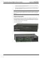
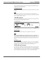
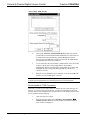
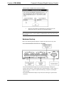
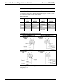
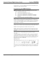
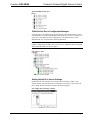
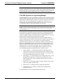
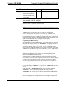
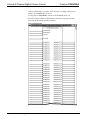
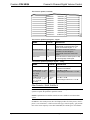
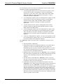
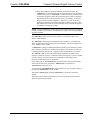
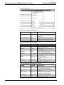
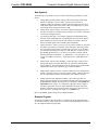
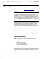
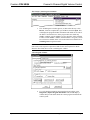
Crestron C2N-VEQ4
Cresnet 4-Channel Digital Volume Control
Operations Guide
This document was prepared and written by the Technical Documentation department at:
Crestron Electronics, Inc.
15 Volvo Drive
Rockleigh, NJ 07647
1-888-CRESTRON
All brand names, product names and trademarks are the property of their respective owners.
©2005 Crestron Electronics, Inc.
Crestron C2N-VEQ4
Cresnet 4-Channel Digital Volume Control
Contents
Cresnet 4-Channel Digital Volume Control: C2N-VEQ4
1
Introduction ............................................................................................................................... 1
Features and Functions................................................................................................ 1
Specifications .............................................................................................................. 3
Physical Description.................................................................................................... 4
Industry Compliance ................................................................................................... 7
Setup .......................................................................................................................................... 7
Network Wiring........................................................................................................... 7
Identity Code ............................................................................................................... 8
Hardware Hookup ..................................................................................................... 11
Programming Software............................................................................................................ 13
Earliest Version Software Requirements for the PC ................................................. 13
Programming with the Crestron SystemBuilder........................................................ 13
Programming with SIMPL Windows........................................................................ 14
Uploading and Upgrading ....................................................................................................... 26
Communication Settings ........................................................................................... 26
Uploading a SIMPL Windows Program ................................................................... 28
Firmware Upgrade..................................................................................................... 30
Problem Solving ...................................................................................................................... 31
Troubleshooting ........................................................................................................ 31
Further Inquiries........................................................................................................ 32
Future Updates .......................................................................................................... 32
Return and Warranty Policies.................................................................................................. 33
Merchandise Returns / Repair Service ...................................................................... 33
CRESTRON Limited Warranty ................................................................................ 33
Operations Guide - DOC. 6135A
Contents • i
Crestron C2N-VEQ4
Cresnet 4-Channel Digital Volume Control
Cresnet 4-Channel Digital Volume
Control: C2N-VEQ4
Introduction
Features and Functions
The Crestron® C2N-VEQ4 Cresnet® 4-Channel Digital Volume Control module is a
digitally controlled 4-channel audio processor that incorporates volume, tone, mixer
and equalization capabilities. Each channel has independent settings for volume,
treble, bass, mute, and mixer controls plus a 12-band parametric equalizer.
Volume/tone controls are compatible with both X-Generation and 2-Series control
systems. Equalization and mixer controls are only accessible from 2-Series
processors.
Refer to the simplified block diagram provided on the next page.
Functional Summary
•
•
•
•
•
•
Four balanced/unbalanced audio I/O channels
24-bit 96KHz A/D and D/A converters with dual DSPs provide
improved audio quality
Independent settings for volume, treble, bass, and mute per channel
4 x 4 matrix mixer controls set the percentage of each input desired at
each output (any input to any output)
Five modes of audio equalization per channel
- a ten-band graphic equalizer and two-band parametric equalizer
- a five-band graphic equalizer and seven-band parametric equalizer
- a speech-optimized five-band graphic equalizer and seven-band
parametric equalizer
- a three-band graphic equalizer and nine-band parametric equalizer
- a full twelve-band parametric equalizer
Touch settable ID capable
Volume, bass, and treble ramp times, scaling, preset levels, and volume muting may
be specified on a per-channel basis. All of these aspects are software controllable.
Volume, bass, and treble control may be sent to more than one channel via software
to support stereo applications.
Operations Guide - DOC. 6135A
Cresnet 4-Channel Digital Volume Control: C2N-VEQ4 • 1
Cresnet 4-Channel Digital Volume Control
Crestron C2N-VEQ4
Input and output connections are completely independent of each other. Therefore, it
is possible to have a balanced input paired with an unbalanced output and vice-versa.
The treble and bass controls are independent from volume and are individually
controlled for each channel. Each channel includes a muting relay with 100 dB
attenuation. When the signal driving Mute1 goes high, the muting circuit is activated
providing 100 dB attenuation from any preset volume level. Likewise, channels “2,”
“3,”and “4” drive Mute2, Mute3, and Mute4, respectively. When the muting signal
goes low, the muting circuit is deactivated and the volume and tone return to their
original preset levels.
NOTE: MuteAll is an override. All channels are muted when this signal is high.
When it is low, the channels follow the state of Mute1, Mute2, Mute3 and Mute4.
Each of the four channels has a twelve-filter parametric equalizer that permits you to
correct for acoustical distortions in the listening area or in the speakers themselves,
and/or to establish preset values that enhance the sound conditions for favorite music
or recording media.
Equalization controls are programmable using Crestron’s Digital Media Tools (DMT)
software or SIMPL Windows (SIMPL). Refer to “Programming Software” on page
13 for details.
The 12 filters are identical in function. Each delivers up to 12 dB of boost or cut
when using DMT software; from -36 dB to +24 dB in a SIMPL program. Each filter
also has an adjustable bandwidth control (from 0.02 octaves to 2 octaves using DMT
software; from 0.02 octaves to 3.5 octaves using SIMPL), and a center frequency
control range (from 25 Hz to 19.9 kHz from DMT; from 5 Hz to 24 kHz using
SIMPL). Use each filter anywhere in the audio spectrum, not just pre-selected ranges
as typically found on graphic equalizers. In addition, you can select from among five
filter types (low pass, high pass, peaking EQ (equalization)/notch, bass shelf, and
treble shelf) or select no filter.
Each channel is equipped with protective relays that turn ON only after safe
conditions are sustained by the electronic circuitry. This feature protects the output
from “pops” caused by accidental power-down/up conditions to the C2N-VEQ4.
If the C2N-VEQ4 is under program control and the power is cycled to the
C2N-VEQ4, it renews the volume, bass, and treble levels to the current program
settings. The mute status (per channel and the mute-all) is also restored.
C2N-VEQ4 Simplified Block Diagram
2 • Cresnet 4-Channel Digital Volume Control: C2N-VEQ4
Operations Guide - DOC. 6135A
Crestron C2N-VEQ4
Cresnet 4-Channel Digital Volume Control
Specifications
The table after this paragraph provides a summary of specifications for the
C2N-VEQ4 module.
Specifications of the C2N-VEQ4
SPECIFICATION
Cresnet Power Usage
8.0 Watts (0.3 Amp @ 24 VDC)
12
Default Net ID
Control System Update Files
1, 2, 3
2-Series Control System
CNMSX-AV/PRO
CNRACKX/-DP
ST-CP
CEN/CN-TVAV
Version 2.004.CUZ or later
Version 5.12.63X.UPZ or later
Version 5.12.63W.UPZ or later
Version 4.02.4S.UPZ or later
Version 5.12.63V.UPZ or later
C2N-VEQ4 Firmware
C2N-VEQ4.1.35.upg
Input Channels (labeled 1 – 4)
Two 5-pin mini-connectors: two channels plus ground
per connector.
Output Channels (labeled 1 – 4)
Two 5-pin mini-connectors: two channels plus ground per
connector.
Output Channel Volume
-80 dB to +20 dB
Input channel mixer controls
-80 dB to 0 dB
NET
One – Cresnet 4-wire interface (24, Y, Z, G)
®
Volume (per channel)
-80dB to +20dB, 0.5dB control step [balanced I/O]
Mute (per channel)
> -100dB
Tone (per channel)
Bass 3dB @ 250 Hz
Bass gain range
Bass step size
Treble 3dB @ 6 kHz
Treble gain range
Treble step size
Parametric EQ Filter
Gain
±15dB
0.5Db
±15dB
0.5dB
±12 dB, 0.1 dB steps (DMT); +24/-36 dB, 0.1 dB steps
(SIMPL)
0.02 to 2.00 octaves (DMT); 0.02 to 3.50 (SIMPL)
25 Hz to 19.9 kHz (DMT); 5 Hz to 24 kHz (SIMPL)
Low pass, high pass, EQ filter (peaking/notching), bass
shelf, and treble shelf
Filter bandwidth
Filter center bandwidth
Filter types
Graphic EQ Filter Gain
±12 dB, 0.1 dB steps
Frequency response
±0.1dB 20-22kHz
±0.5dB 10Hz-30kHz
Total harmonic distortion (THD)
+ Noise
<0.008% @1kHz
S/N ratio
>97dB balanced, >95dB unbal., 20Hz-22kHz A-weighted
Crosstalk
> -90dB 20Hz-22kHz
Common mode rejection
> 90dB 20Hz-22kHz
Input level (max.)
4Vrms balanced, 2Vrms single-ended
Input impedance
10K ohms balanced, 5K ohms single-ended
Output level
4Vrms balanced, 2Vrms single-ended
Output impedance
200 ohms balanced, 100 ohms single-ended
Environmental temperature
32° to 122°F (0° to 50°C)
Humidity
10% to 90% RH (non-condensing)
Dimensions
Height:
Width:
Depth:
Weight
1.86 lb (0.837 kg)
1.
Operations Guide - DOC. 6135A
DETAILS
1.80 in (4.57 cm)
7.07 in (17.96 cm)
6.32 in (16.05 cm)
The latest versions can be obtained from the Crestron website. Refer to NOTE after last footnote.
Cresnet 4-Channel Digital Volume Control: C2N-VEQ4 • 3
Cresnet 4-Channel Digital Volume Control
Crestron C2N-VEQ4
2.
Crestron 2-Series control systems include the AV2 and PRO2. Consult the latest Crestron Product
Catalog for a complete list of 2-Series control systems.
3.
Filenames for CNX and ST-CP update files have a UPZ extension. Files on the website may be .zip or
self-extracting .exe files containing the .cuz or .upz file. All can be obtained from the Downloads
section of the Crestron website. To avoid program problems, make sure you are using the update file
with the correct suffix letter (e.g., S, V, W, X).
NOTE: Crestron software and any files on the website are for Authorized Crestron
dealers and Crestron Authorized Independent Programmers (CAIP) only. New users
may be required to register to obtain access to certain areas of the site (including the
FTP site).
Physical Description
The C2N-VEQ4, shown below, is housed in a black enclosure with labeling on the
front and rear panels. Six LEDs on the front of the unit indicate the unit’s status. All
connections are made on the back of the unit. There are four rubber feet on the base
of the unit for stability and to prevent slippage.
C2N-VEQ4 Physical Views
4 • Cresnet 4-Channel Digital Volume Control: C2N-VEQ4
Operations Guide - DOC. 6135A
Crestron C2N-VEQ4
Cresnet 4-Channel Digital Volume Control
C2N-VEQ4 Overall Dimensions
1.50 in
(3.81 cm)
6.94 in
(17.63 cm)
6.32 in
(16.05 cm)
7.07 in
(17.96 cm)
1.80 in
(4.57 cm)
1.70 in
(4.32 cm)
C2N-VEQ4 Ports
All connections to the C2N-VEQ4 are made through the ports on the rear panel. Refer
to the illustrations and descriptions, which follow.
C2N-VEQ4 Ports
IN and OUT Connectors
These four mini connectors provide four channels of balanced/unbalanced audio input
(IN 1-4) and four channels of balanced/unbalanced audio output (OUT 1-4). Connect
the balanced/unbalanced input (IN) ports to the audio output of any A/V equipment
that needs volume, treble, bass, mixer, and/or equalization control. Connect the
Operations Guide - DOC. 6135A
Cresnet 4-Channel Digital Volume Control: C2N-VEQ4 • 5
Cresnet 4-Channel Digital Volume Control
Crestron C2N-VEQ4
balanced/unbalanced output (OUT) ports to an amplifier. Each channel includes a
muting relay with 100 dB attenuation.
G (Chassis Ground)
Use this chassis screw to ground the unit to the amplifier and audio source common
grounds.
NET
This 4-pin network connector is used to connect the C2N-VEQ4 module to the
Cresnet system. Data and power for the C2N-VEQ4 are provided via the connection.
Refer to “Network Wiring” on page 7.
C2N-VEQ4 Indicators
There are six LED indicators located on the front panel of the C2N-VEQ4. Refer to
the illustration below and descriptions that follow.
C2N-VEQ4 Indicators
PWR (Power)
This green LED illuminates when power is supplied to the C2N-VEQ4.
NET
This yellow LED illuminates when communication between the control system and
the C2N-VEQ4 is established (the unit is polled on the network). Illumination
indicates that the program currently loaded has a network device defined at the same
ID as the C2N-VEQ4. The LED flashes when communication with the processor
occurs.
ACTIVITY (1 – 4)
These red LEDs illuminate only when there is activity on any of the four channels.
Activity includes any change in volume, tone (bass, treble), mixer, or equalization
parameters. Once the command is completed, the related LED(s) go out.
SETUP LED and Pushbutton
The C2N-VEQ4 is TSID ready. The SETUP pushbutton and its associated LED are
located on the rear panel and are used for setup of the unit’s network ID during the
initial configuration of a Cresnet® system or when the device is being added/replaced.
Refer to “Method B (Touch Settable IDs)” on page 9 for detailed information.
6 • Cresnet 4-Channel Digital Volume Control: C2N-VEQ4
Operations Guide - DOC. 6135A
Crestron C2N-VEQ4
Cresnet 4-Channel Digital Volume Control
Industry Compliance
As of the date of manufacture, the C2N-VEQ4 has been tested and found to comply
with specifications for CE marking and standards per EMC and
Radiocommunications Compliance Labelling.
NOTE: This device complies with part 15 of the FCC rules. Operation is subject to
the following two conditions: (1) these devices may not cause harmful interference,
and (2) these devices must accept any interference received, including interference
that may cause undesired operation.
Setup
Network Wiring
CAUTION: In order to ensure optimum performance over the full range of your
installation topology, Crestron Certified Wire, and only Crestron Certified Wire,
should be used. Failure to do so may incur additional charges if support is required to
identify performance deficiencies as a result of using improper wire.
CAUTION: Use only Crestron power supplies for Crestron equipment. Failure to do
so could cause equipment damage or void the Crestron warranty.
CAUTION: Provide sufficient power to the system. Insufficient power can lead to
unpredictable results or damage to the equipment. Please use the Crestron Power
Calculator to help calculate how much power is needed for the system
(http://www.crestron.com/calculators).
NOTE: When installing network wiring, refer to the latest revision of the wiring
diagram(s) appropriate for your specific system configuration, available from the
Crestron website.
When calculating the wire gauge for a particular Cresnet run, the length of the run
and the Cresnet power usage of each network unit to be connected must be taken into
consideration. If Cresnet units are to be daisy-chained on the run, the Cresnet power
usage of each unit to be daisy-chained must be added together to determine the
Cresnet power usage of the entire chain. If the unit is a home-run from a Crestron
system power supply network port, the Cresnet power usage of that unit is the Cresnet
power usage of the entire run. The length of the run in feet and the Cresnet power
usage of the run should be used in the following resistance equation to calculate the
value on the right side of the equation.
Resistance Equation
40,000
R< LxP
Operations Guide - DOC. 6135A
Where: R = Resistance (refer to the following table).
L = Length of run (or chain) in feet.
P = Cresnet power usage of entire run (or chain).
Cresnet 4-Channel Digital Volume Control: C2N-VEQ4 • 7
Cresnet 4-Channel Digital Volume Control
Crestron C2N-VEQ4
The required wire gauge should be chosen such that the resistance value is less than
the value calculated in the resistance equation. Refer to the following table.
Wire Gauge Values
RESISTANCE
WIRE GAUGE
4
16
6
18
10
20
15
22
13
Doubled CAT 5
8.7
Tripled CAT 5
NOTE: All Cresnet wiring must consist of two twisted pairs. One twisted pair is the
+24V conductor and the GND conductor, and the other twisted pair is the Y
conductor and the Z conductor.
NOTE: When daisy-chaining Cresnet units, strip the ends of the wires carefully to
avoid nicking the conductors. Twist together the ends of the wires that share a pin on
the network connector, and tin the twisted connection. Apply solder only to the ends
of the twisted wires. Avoid tinning too far up the wires or the end becomes brittle.
Insert the tinned connection into the Cresnet connector and tighten the retaining
screw. Repeat the procedure for the other three conductors.
Identity Code
Every equipment and user interface within the network requires a unique identity
code (Net ID). These codes are recognized by a two-digit hexadecimal number from
03 to FE. The Net ID of each unit must match an ID code specified in the SIMPL
Windows program. Refer to “Setting the Net ID in Device Settings” on page 15 for
details of the SIMPL Windows procedure.
Refer to the note on page 26 for
a definition of Viewport.
The Net ID of the C2N-VEQ4 has been factory set to 12. The Net IDs of multiple
C2N-VEQ4s in the same system must be unique. Net IDs are changed from a
personal computer (PC) via the Crestron Viewport.
NOTE: For detailed information on establishing communication between the PC and
control system, refer to “Communication Settings” on page 26. If communication
cannot be established, refer to the “Troubleshooting Communications” section in the
respective Operations Guide for the control system.
There are two different methods—Method A or Method B—for setting the
C2N-VEQ4 Net IDs:
Method A (Cresnet address-settable ID), described on page 9, applies to
C2N-VEQ4s in a Cresnet system with a CNX control system or with a 2-Series
control system upgrade file (CUZ) version prior to 3.008, but can be used with later
versions of firmware and requires that a single unit be the only network device
connected to the control system.
Method B (Touch Settable IDs), which begins on page 9, applies to C2N-VEQ4s in a
Cresnet system with 2-Series control system upgrade file (CUZ) version 3.029 or
later. These upgrades enable Touch Settable ID (TSID) functionality, which makes it
8 • Cresnet 4-Channel Digital Volume Control: C2N-VEQ4
Operations Guide - DOC. 6135A
Crestron C2N-VEQ4
Cresnet 4-Channel Digital Volume Control
possible for the control system to recognize a network device via its serial number,
which is stored in the device’s memory. This method does not require that any
devices be disconnected from the network; Net IDs may be set with the entire Cresnet
system intact. This method requires the use of the Crestron Viewport version 3.35 or
later.
Use the appropriate method to set the C2N-VEQ4 Net ID.
Method A (Cresnet address-settable ID)
1.
Ensure that the C2N-VEQ4 is the only device connected to the control
system.
2.
Open the Crestron Viewport.
3.
From the Viewport menu, select Functions | Set Network ID. The
software checks the baud rate and then opens the "Set Network ID"
window.
4.
In the "Set Network ID" window, select the C2N-VEQ4 from the
Current Network Devices text window.
5.
Select the new Net ID for the C2N-VEQ4 from the Choose the new
network ID for the selected device (Hex): text box.
6.
Click Set ID to initiate the change. This will display the "ID command
has been sent" window.
7.
In the "Command Complete" window, click OK.
8.
In the Current Network Devices text window, verify the new Net ID
code.
9.
In the "Set Network ID" window, click Close.
NOTE: The new Net ID code may also be verified by selecting Diagnostic | Report
Network Devices in the Viewport (alternately, select F4).
10.
Repeat this procedure for each C2N-VEQ4 to be added to the system.
Method B (Touch Settable IDs)
Before using this method, you should have a list of all current network devices and
their Net IDs, to avoid assigning duplicate IDs.
Set Net ID by TSID
These procedures are for TSID-enabled network devices during the initial
configuration of a Cresnet system or when such devices are being added/replaced.
Operations Guide - DOC. 6135A
1.
Ensure that all C2N-VEQ4s are connected to the control system.
2.
Open the Crestron Viewport version 3.35 or later.
3.
From the Viewport menu, select Functions | Assign Cresnet ID by
Serial Number. The “Set Net ID by TSID” window appears. The
window is first displayed with the data fields empty.
Cresnet 4-Channel Digital Volume Control: C2N-VEQ4 • 9
Cresnet 4-Channel Digital Volume Control
Crestron C2N-VEQ4
“Set Net ID by TSID” Window
4.
Click on the Search for Touch Settable Devices button. The system
searches the network and lists all TSID-enabled devices found. The list
is similar to the report produced by pressing F4 (Report Network
Devices); the first eight digits of each line constitute the TSID number
(hexadecimal form of the serial number).
5.
As you enter either the serial number or TSID number of the device that
requires a change, the corresponding TSID or serial number
automatically appears in its appropriate field, and the list scrolls to and
highlights the device listing. The listing should show the device’s
current Cresnet ID.
6.
Enter the Cresnet ID that the device should be set to and click OK. The
number you enter should appear on the list.
CAUTION: This function does not prevent you from setting duplicate IDs. Be sure
to check current assignments before entering the desired Cresnet ID number.
Serial Number to TSID Conversion
This utility is useful in a case where there are multiple devices of the same type on a
network, you need to locate a particular one, you know the TSID but not the serial
number, and your site installation list is based on device serial numbers. In this (or the
reverse) situation, do the following:
1.
Open the Crestron Viewport.
2.
From the Viewport menu, select Functions | Serial Number ÅÆ
TSID Conversion Tool. The “Serial Number ÅÆTSID Conversion
Tool” window is displayed.
10 • Cresnet 4-Channel Digital Volume Control: C2N-VEQ4
Operations Guide - DOC. 6135A
Crestron C2N-VEQ4
Cresnet 4-Channel Digital Volume Control
“Serial Number to TSID Conversion Tool” Window
3.
Enter the serial number or TSID number as instructed; press the
appropriate button to obtain the corresponding number.
NOTE: Enter serial numbers, including spaces, exactly as they appear on the unit
label. Alpha characters in serial numbers or TSID numbers may be entered in upper
or lower case.
Hardware Hookup
Refer to the following hookup diagram. Complete the connections in any order.
Cresnet System Hookup Connections for C2N-VEQ4
Four balanced/unbalanced inputs are provided for audio input, utilizing fiveposition mini-connectors. Audio inputs may be balanced using (+) and (-) inputs, or
unbalanced using (+) input for signal and connecting (-) input to (G) and signal
source ground.
Four balanced/unbalanced outputs are provided, also utilizing five-position miniconnectors.
Operations Guide - DOC. 6135A
Cresnet 4-Channel Digital Volume Control: C2N-VEQ4 • 11
Cresnet 4-Channel Digital Volume Control
Crestron C2N-VEQ4
NOTE: An unbalanced input may use a balanced or unbalanced output. Likewise, a
balanced input may use a balanced or unbalanced output.
For connection details, refer to the following table and diagrams. Channels 1 and 2
are used as typical for all input and output channels.
Audio Connections
SIGNAL BALANCED
NAME
AUDIO
INPUT
BALANCED
AUDIO
OUTPUT
UNBALANCE
D AUDIO
INPUT
UNBALANCE
D AUDIO
OUTPUT
+
1+
1+
1 + In
1 + Out
-
1-
1-
1 - signal return,
jumper to GND
OPEN
G
Shield/ground
Shield/ground
Ground
Common ground
+
2+
2+
2 + In
2 + Out
-
2-
2-
2 - signal return,
jumper to GND
OPEN
Typical Balanced/Unbalanced Inputs and Outputs
INPUT CHANNELS 1 & 2
OUTPUT CHANNELS 1 & 2
NOTE: Using the unbalanced configuration for the audio output reduces the total
audio gain by 6 dB.
12 • Cresnet 4-Channel Digital Volume Control: C2N-VEQ4
Operations Guide - DOC. 6135A
Crestron C2N-VEQ4
Cresnet 4-Channel Digital Volume Control
Programming Software
Have a question or comment about Crestron software?
Answers to frequently asked questions (FAQs) can be viewed in the Online Help
section of the Crestron website. To post a question or view questions you have
submitted to Crestron’s True Blue Support, log in at http://support.crestron.com./
First-time users will need to establish a user account.
You can create a program that allows you to include the C2N-VEQ4 in a Crestron
control system using the Crestron programming tools Crestron SystemBuilder™ and
SIMPL Windows. These tools are intended for users with different levels of
programming knowledge. The flexibility of each tool is proportional to the degree of
programming expertise (i.e., the more flexible, the more a programmer needs to know
and account for). Of course, one can initiate programming using the easiest method
(SystemBuilder) and use advanced techniques that are available from SIMPL
Windows to customize the job.
Earliest Version Software Requirements for the PC
NOTE: Crestron recommends that you use the latest software to take advantage of
the most recently released features. The latest software is available from the Crestron
website.
•
(Optional) SystemBuilder version 2.0 or later. Requires SIMPL Windows
and Crestron Engraver. Requires SystemBuilder templates 1.10 or later.
•
SIMPL Windows version 2.05.22 or later.
Requires SIMPL+ Cross Compiler version 1.1.
•
Crestron Database version 16.4.4 or later. Required by SIMPL Windows.
•
Crestron Engraver version 2.3.3.2 (required if using SystemBuilder).
•
Digital Media Tools version 1.01.01 or later, with configuration template for
C2N-VEQ4.
The Digital Media Tools software is the preferred method to adjust equalization. In
fact, if you want to use a graphic equalizer, you MUST use Digital Media Tools,
because this is where the default graphic equalizer characteristics are set up. Refer to
page 16 for more details on using Digital Media Tools.
Programming with the Crestron SystemBuilder
The easiest method of
programming, but does not
offer as much flexibility as
SIMPL Windows.
The Crestron SystemBuilder offers automatic programming for such residential and
commercial applications as audio distribution, home theater, video conferencing,
and lighting. The interface of this tool guides you through a few basic steps for
designating rooms and specifying the control system, touchpanels, devices, and
functionality. The Crestron SystemBuilder then programs the system, including all
touchpanel projects and control system logic.
Crestron SystemBuilder is fully integrated with Crestron's suite of software
development tools, including SIMPL Windows, Crestron VisionTools® Pro-e
(VT Pro-e), Crestron Engraver, Crestron Database, User IR Database, and User
Operations Guide - DOC. 6135A
Cresnet 4-Channel Digital Volume Control: C2N-VEQ4 • 13
Cresnet 4-Channel Digital Volume Control
Crestron C2N-VEQ4
Modules Directory. Crestron SystemBuilder accesses these tools behind the scenes,
enabling you to easily create robust systems.
Programming with SIMPL Windows
NOTE: The following are acceptable file extensions for programs that include a
C2N-VEQ4, developed for specific control system types:
.smw projectname.smw (source file)
.spz
projectname.spz (compiled file for 2-series)
.bin
projectname.bin (compiled file for CNX generation)
.csz
projectname.csz (compiled file for CNX generation with SIMPL+)
.ush projectname.ush (compiled file for CNX generation with SIMPL+
header file)
.usp projectname.usp (source code module for SIMPL+)
SIMPL Windows is Crestron's software for programming Crestron control systems. It
provides a well-designed graphical environment with a number of workspaces (i.e.,
windows) in which a programmer can select, configure, program, test, and monitor a
Crestron control system. SIMPL Windows offers drag and drop functionality in a
familiar Windows® environment.
NOTE: The following descriptions assume that the reader has knowledge of SIMPL
Windows. If not, refer to the extensive help information provided with the software.
NOTE: In the following description, the PRO2 control system is used.
NOTE: Volume/tone controls are compatible with both X-Generation and 2-Series
control systems. Equalization and mixer controls are only accessible from 2-Series
processors.
This section describes a sample SIMPL Windows program that includes a
C2N-VEQ4.
Configuration Manager is where programmers “build” a Crestron control system by
selecting hardware from the Device Library. In Configuration Manager, drag the
PRO2 from the Control Systems folder of the Device Library and drop it in the upper
pane of the System Views. The PRO2 with its associated communication ports is
displayed in the System Views upper pane.
PRO2 System View
The System Views lower pane displays the PRO2 system tree (refer to graphic on the
next page). This tree can be expanded to display and configure the communications
ports.
14 • Cresnet 4-Channel Digital Volume Control: C2N-VEQ4
Operations Guide - DOC. 6135A
Crestron C2N-VEQ4
Cresnet 4-Channel Digital Volume Control
Expanded PRO2 System Tree
C2Net Device Slot in Configuration Manager
To incorporate a C2N-VEQ4 into the system, drag the C2N-VEQ4 from the Cresnet
Control Modules | Cresnet Audio Modules folder of the Device Library and drop it in
System Views. The PRO2 system tree displays the C2N-VEQ4 in Slot 9, with a
default Net ID of 12 as shown in the following illustration.
NOTE: The first C2N-VEQ4 in a system is preset with a Net ID of 12 when its
symbol is dragged into the upper pane of System Views. Additional units are assigned
different Net ID numbers as they are added.
C2Net Device, Slot 9
Setting the Net ID in Device Settings
Double-click the C2N-VEQ4 icon to open the “Device Settings” window. This
window displays the C2N-VEQ4 device information. If necessary, select the Net ID
tab to change the unit’s Net ID, as shown in the following figure.
C2N-VEQ4 “Device Settings” Window
Operations Guide - DOC. 6135A
Cresnet 4-Channel Digital Volume Control: C2N-VEQ4 • 15
Cresnet 4-Channel Digital Volume Control
Crestron C2N-VEQ4
NOTE: SIMPL Windows automatically changes Net ID values of a device added to a
program if a duplicate device or a device with the same default Net ID already exists
in the program. Always ensure that the hardware and software settings of the Net ID
match. For Net ID hardware setting details, refer to “Identity Code” on page 8.
C2N-VEQ4 Symbols in Programming Manager
Programming Manager is where programmers “program” a Creston control system by
assigning signals to symbols. Due to the extensive functionality of the C2N-VEQ4, a
single symbol in SIMPL Windows would be too complex. Instead, the C2N-VEQ4 is
broken up into slots. In Program Manager, expand the C2N-VEQ4 to view the
individual slots, and then drag the desired symbol to Detail View. The slots and
corresponding symbols are described beginning on the next page.
NOTE: The volume, bass, treble, and mixer program settings are stored in the
SIMPL program; the C2N-VEQ4 assumes a zero value for each of them. The EQ trim
and filter control settings are stored in the unit itself, and can be activated using
“recall” functions.
The full parametric equalization controls built into the C2N-VEQ4 provide graphic
and parametric equalization, programmable using Crestron's Digital Media Tools
software or SIMPL Windows. The Digital Media Tools (DMT) software is free and
available from the download section of the Crestron website.
Almost all users will use the Digital Media Tools and not the SIMPL Windows
symbol to adjust equalization because of the program’s simplicity, speed, and ease of
operation. From the point of view of the symbols, everything is parametric
equalization; graphic equalizers are just parametric equalizers with specific default
frequencies, Q (bandwidth), and type. If you want to use a graphic equalizer, you
MUST use Digital Media Tools, because this is where the default graphic equalizer
characteristics are set up. Programmers might want to set up sliders from the
TrimBand gains to let the user modify slightly what the programmer has stored.
The C2N-VEQ4 adjustments in Digital Media Tools contain five tabs:
•
Room Calibration – for analyzing the room and compensating for any
unwanted effects (such as noise from an HVAC system, reflections from
hard surfaces, and resonance at particular frequencies) so the listener hears
what was intended when the material was recorded.
•
Input Settings – for setting the input levels for analog audio sources. Using
this adjustment properly lets you compensate for analog sources with
different input levels to obtain a seamless transition between sources at a
given volume level.
•
Graphic EQ – for choosing the number of graphic equalizers, and provides
access to the graphic equalizer sliders
•
Parametric EQ – for making parametric equalization adjustments
•
Communications – for setting up communications and adjusting the
equalizer in real time.
For additional details, refer to the Digital Media Tools help file.
16 • Cresnet 4-Channel Digital Volume Control: C2N-VEQ4
Operations Guide - DOC. 6135A
Crestron C2N-VEQ4
Example Program
Cresnet 4-Channel Digital Volume Control
NOTE: Before attempting to program the equalization controls in SIMPL Windows,
please study the example program. (Refer to “Example Program” on page 25.)There
are some subtleties that must be carefully handled. For example, if you intend to
directly set one of the TrimBandOut signals in your program, and the
TrimBandOut_FB signal can be set to a different value by some other method (using
DMT software or recalling presets), do not jam the TrimBandOut_FB signal back to
the TrimBandOut. Oscillations might result between the directly driven value and the
different feedback value. Instead, use an Analog Increment with Optional Feedback
symbol. Connect the directly driven value and the TrimBandOut_FB signal to
individual inputs. Connect its output to the TrimBandOut input of the C2N-VEQ4.
The same logic applies to any value that can be changed in two places. Refer to the
example program.
General Audio Controls – Slot 9, SubSlot 1
Refer to the table that follows the symbol for a list of inputs and their functional
descriptions.
General Audio Controls Symbol
The C2N-VEQ4 symbol is defined by the assigned inputs. The diagram above shows
the C2N-VEQ4 symbol in SIMPL Windows.
Operations Guide - DOC. 6135A
Cresnet 4-Channel Digital Volume Control: C2N-VEQ4 • 17
Cresnet 4-Channel Digital Volume Control
Crestron C2N-VEQ4
C2N-VEQ4 General Audio Controls Symbol Input Descriptions
Signal Type
Name
Value
Definition
Digital
MuteOut (1 through 4)
plus MuteAll
1/0
High = Mute On
Low = Mute Off
Analog
VolOut (1 through 4)
0 to 100%
-80dB to +20dB
0 to 100%
± 15dB
0 to 100%
± 15dB
0% = Volume set to lowest
100% = Volume set to Highest
50%=Flat Treble
0%= -15dB — 100%= +15dB
50%=Flat Bass
0%= -15dB — 100%= +15dB
TrebOut (1 through 4)
BassOut (1 through 4)
Mixer Controls – Slot 9, SubSlot 2
The 4x4 matrix mixer controls provide the equivalent of a small-scale mixing board.
These controls use a logarithmic scale (0dB to –80dB) with 0dB corresponding to 0
attenuation; anything –80dB and below will mute the signal. The C2N-VEQ4 expects
values ranging from 0d to –800d (and lower), 0.1dB per count, to appear at each
output. (Refer to the signal description table on the next page.) You can direct any
input or combination of inputs to any output, via analog variables in the SIMPL
program.
NOTE: Mixer controls are not accessible in an X-Generation system.
C2N-VEQ4 Mixer Controls Symbol
18 • Cresnet 4-Channel Digital Volume Control: C2N-VEQ4
Operations Guide - DOC. 6135A
Crestron C2N-VEQ4
Cresnet 4-Channel Digital Volume Control
C2N-VEQ4 Mixer Controls Symbol Input Descriptions
Signal Type
Name
Value
Definition
Analog
In1-For-Out1 through In4For-Out1; In1-For-Out2
through In4-For-Out2; In1For-Out3 through In4-ForOut3; In1-For-Out4 through
In4-For-Out4
0 to -800
0dB to –80dB
Each analog increment of 1 = 0.1 dB
Trim Controls – Slot 9, SubSlot 3
NOTE: Minimum operating firmware version 3.039 is required for 2-Series control
systems to operate the parametric equalizer features.
NOTE: Equalization trim/filter controls are not available in an X-Generation system.
TrimBand
TrimBand refers to a modification of the gain of the forty graphic filters.
There are ten trim presets. A trim preset is a set of all forty TrimBands. (The
TrimBands are not labeled with actual frequency values since they can be changed in
the Digital Media Tools or by setting the full parametric filters in the symbol.) Trim
presets can be used to modify the soundfield for different kinds of music where you
might want to emphasize the bass, or bring out a treble frequency.
Programming in SIMPL Windows
Signal Descriptions
Each channel has a set of ten TrimBand inputs. The TrimBand inputs only adjust the
gains of the gain-adjustable filters; thus <TrimBand1-1> corresponds to channel 1,
filter 1; <TrimBand1-2> corresponds to channel 1, filter #2; <TrimBand2-1>
corresponds to channel 2, filter 1, and so forth. The gains are adjustable within a
range of -10dB to +10dB. All TrimBand values propagate immediately to the outputs.
TrimBand values are added to the gain values of the filters. If Gain = 10 dB and Trim
= -3 dB, the result is 7 dB
Valid values for TrimBand range from -120 (-12dB) to +120 (+12dB). 2-Series
symbols such as the Analog Scaler with I/O Limits and Analog Ramp (Bounds
Limited) can handle range and sign mapping.
A TrimBand value of 0 (0dB) means that the signal will pass unaffected. Values
above and below 0 boost or reduce the gain in increments of 0.1dB. That is, changing
the analog value by one signifies a change in boost or attenuation of 0.1 decibel.
The C2N-VEQ4 provides ten trim presets, where a trim preset is a set of all forty
TrimBand values.
On the rising edge of <SaveTrimPreset>, the forty TrimBand values will be stored in
the preset specified by <TrimPreset#>. Valid values for <TrimPreset#> range from
1 to 10.
On the rising edge of <RecallTrimPreset> the values stored in the indicated
<TrimPreset#> will be recalled and propagated to the outputs. Here the
<TrimBand#-#_FB> outputs may have different values than the TrimBand inputs
(the only time these values will differ).
If <RecallTrimPreset> goes high and <TrimPreset#> is set to an invalid value (out
of the 1 to 10 range) all trim settings will be cleared, and all signals will pass with
Operations Guide - DOC. 6135A
Cresnet 4-Channel Digital Volume Control: C2N-VEQ4 • 19
Cresnet 4-Channel Digital Volume Control
Crestron C2N-VEQ4
whatever gain setting was in effect. This is the same as recalling a trim preset in
which every TrimBand value is set to 0.
A rising edge of <ClearTrims> will also set all TrimBand values to 0.
The Trim Controls symbol is illustrated below and on the next page; the tables
following the illustrations provide join details.
Trim Controls Symbol
20 • Cresnet 4-Channel Digital Volume Control: C2N-VEQ4
Operations Guide - DOC. 6135A
Crestron C2N-VEQ4
Cresnet 4-Channel Digital Volume Control
Trim Controls Symbol (continued)
Trim Controls Symbol Input Signals – Digital
NAME
VALUE
DEFINITION
SaveTrimPreset
1/0
RecallTrimPreset
1/0
Clear Trims
1/0
Saves current trim values on the given
TrimPreset#, on the rising edge of the
signal. TrimPreset# range is 1 – 10.
Recalls the current trim values on
TrimBand 1-10 from the given
TrimPreset# on the rising edge of the
signal.
Clears all of the trim values (sets to 0 dB)
on the rising edge of this signal.
Trim Controls Symbol Input/Output Signals – Analog
NAME
VALUE
DEFINITION
TrimPreset#
1 to 10
TrimBandOut1-1 – 1-10,
2-1 - 2-10, 3-1 – 3-10,
4-1 – 4-10
(40 total)
TrimBandOut1-1 – 1-10,
2-1 - 2-10, 3-1 – 3-10,
4-1 – 4-10_FB
(40 total)
-120 to
120
10 user-definable trim presets, each
includes all TrimBands
-12 dB to +12 dB
Each analog increment of 1 = 0.1 dB.
-120 to
120
-12 dB to +12 dB
Each analog increment of 1 = 0.1 dB.
Filter Controls – Slot 9, SubSlot 4
NOTE: Minimum operating firmware version 3.039 is required for 2-Series control
systems to operate the parametric equalizer features.
NOTE: Equalization trim and filter controls are not available in an X-Generation
system.
In addition to the 10 trim presets, the C2N-VEQ4 provides five filter presets, where a
preset is a set of 48 filters. A filter consists of the type, center frequency, gain, and the
ratio of the center frequency to the filter bandwidth (also called Q) for each channel.
Operations Guide - DOC. 6135A
Cresnet 4-Channel Digital Volume Control: C2N-VEQ4 • 21
Cresnet 4-Channel Digital Volume Control
Crestron C2N-VEQ4
The C2N-VEQ4 provides twelve filters for each channel, with five modes of audio
equalization (settable using Digital Media Tools):
•
A ten-band graphic equalizer and a two-band parametric equalizer. In this
mode, the first ten filters in all channels are used to set up the default
frequencies (31.5Hz, 63Hz, 125Hz, 250Hz, 500Hz, 1KHz, 2KHz, 4KHz,
8KHz, and 16KHz) for graphic equalization, leaving filters 11 and 12
available for parametric equalization.
•
A five-band graphic equalizer and a seven-band parametric equalizer. In this
mode, the first five filters in all channels are used to set up the default
frequencies (63Hz, 250Hz, 1KHz, and 4KHz, 10KHz) for graphic
equalization, leaving filters 6 through 12 available for parametric
equalization.
•
A speech optimized version of the five-band graphic and seven-band
parametric equalizer arrangement utilizing default frequencies (160Hz,
600Hz, 1KHz, and 2.5KHz, 5KHz)
•
A three-band graphic equalizer and a nine-band parametric equalizer. Here
the first three filters in all channels are for the default frequencies (250Hz,
1KHz, and 4KHz), leaving filters 4 through 12 available for parametric
equalization in case you want to notch out a 60 Hz hum or other resonant
frequency.
•
A full twelve-band parametric equalizer. You may use the equalizer as a full
twelve-band parametric equalizer, however it is recommended that you first
become fully familiar with equalization techniques.
The <FilterType> inputs set the type of filter or equalization. Valid values are as
follows:
0 = Off (No parametric equalization).
1 = Peaking EQ (Permits precise amplitude adjustment of a selectable range of
frequencies, or removes an unwanted frequency from a signal). The
bandwidth range can vary from a small slice of the spectrum to a 3.5-octave
area. Typically, peaking EQ filters allow fine adjustment to compensate for
room acoustics, noise, and speaker limitations.
2 = High Pass (Filters out all audio below the <FilterFreq> levels). A high-pass
filter circuit passes all signals that have a frequency higher than the specified
frequency, while attenuating all frequencies lower than its specified
frequency.
3 = Low Pass (Filters out all audio above <FilterFreq> levels). A low-pass
filter passes all frequencies below the specified frequency, while attenuating
all frequencies above this specified frequency.
4 = Treble Shelf (Uniformly boosts or attenuates all frequencies above the
<FilterFreq> levels, without affecting the frequencies below. The amount of
modification is given by <FilterGain>). A Treble Shelf filter boosts or
attenuates all frequencies above the specified frequency in a uniform manner
while not affecting the low frequencies below the specified frequency. For
example: Because bass frequencies have longer wavelengths, small speakers
may sound distorted when trying to reproduce these frequencies. The Treble
Shelf filter can increase the proportion of treble to bass, enabling the smaller
speakers to produce a clearer sound.
22 • Cresnet 4-Channel Digital Volume Control: C2N-VEQ4
Operations Guide - DOC. 6135A
Crestron C2N-VEQ4
Cresnet 4-Channel Digital Volume Control
5 = Bass Shelf (Uniformly boosts or attenuates all frequencies below the
<FilterFreq> levels without affecting the frequencies above. The amount of
modification is given by <FilterGain>). A Bass Shelf filter uniformly boosts
or attenuates frequencies below the specified frequency while not affecting
high frequencies above the specified frequency. For example: To increase
the gain of bass frequencies applied to a subwoofer, you can set the bass
shelf filter to uniformly increase the amplitude of all bass frequencies. The
Bass Shelf filter can also be used to uniformly decrease the bass frequencies
to eliminate a booming bass sound.
NOTE: Various combinations of these filters may be used to equalize the soundfield
in order to produce a flat response, and reproduce the sound as the recording engineer
originally intended.
The <FilterFreq> input selects the center frequency. Valid values range from 5
(5Hz) to 24000 (24kHz).
The <FilterGain> inputs boost or attenuate the center frequency, or with shelving
filters, all frequencies above or below the center frequency. Valid values range from
-360 (-36dB) to +240 (+24dB).
A <FilterGain> setting of 0 (0dB) means that the signal will pass unaffected. Values
above and below 0 will boost or attenuate the frequency in increments of .1dB. That
is, changing the filter gain value by 1 signifies a boost or attenuation of .1 decibels.
The <FilterQ> input sets the width of the band of frequencies around the center
frequency, expressed in octaves. Valid values range from 0.02 to 3.5 octaves. Smaller
Q values represent a narrow band of boost or attenuation, while larger values
represent a wide band of boost or attenuation.
On the rising edge of <SaveFilterPreset>, the current filter values for all 48 filters
will be stored in the preset specified by <FilterPreset#> Valid values for
<FilterPreset#> range from 1 to 5.
A rising edge of <RecallFilterPreset> will recall the type, gain, frequency and Q of
the specified <FilterPreset#> for all 48 filters.
The outputs <FilterType_F> through <FilterGain_F> report the current filter
settings.
The Filter Controls symbol is illustrated on the next page. Refer to the tables that
follow the symbol for join details.
Operations Guide - DOC. 6135A
Cresnet 4-Channel Digital Volume Control: C2N-VEQ4 • 23
Cresnet 4-Channel Digital Volume Control
Crestron C2N-VEQ4
Filter Controls Symbol
Filter Controls Input Signals – Digital
NAME
VALUE
DEFINITION
SaveFilterPreset
1/0
RecallFilterPreset
1/0
Saves the current filter values into the
given FilterPreset# on the rising edge of
the signal.
Recalls the filter values from the given
FilterPreset# on the rising edge of this
signal.
Filter Controls Input Signals – Analog
NAME
VALUE
DEFINITION
FilterPreset#
1 to 5
Filter#
1 to 48
5 user-definable filter presets, each of
which includes 48 filters
Select filter (1-12 CH1; 13-24 CH2; 25-36
FilterType
0 to 5
FilterFreq
5 to 24000
FilterQ
20 to 3500
FilterGain
-360 to 240
CH3; 37-48 CH4)
0=off, 1=EQ, 2=High Pass, 3=Low Pass,
4=Treble Shelf, 5=Bass Shelf
5 Hz to 24 kHz Each analog increment
of 1 = 1 Hz
0.02 to 3.5 octaves
Each analog increment of 1 = 0.001
octaves
-36 dB to +24 dB Each analog
increment of 1 = 0.1 dB
Filter Controls Symbol Output Signals – Analog
NAME
VALUE
DEFINITION
FilterType_FB
0 to 5
FilterFreq_FB
5 to 24000
FilterQ_FB
20 to 3500
FilterGain_FB
-360 to 240
0=off, 1=EQ, 2=High Pass, 3=Low Pass,
4=Treble Shelf, 5=Bass Shelf
5 Hz to 24 kHz, each analog increment
of 1 = 1 Hz
0.02-3.5 octaves, each analog
increment of 1 = 0.001 octaves
-36 dB to +24 dB, each analog
increment of 1 = 0.1 dB
24 • Cresnet 4-Channel Digital Volume Control: C2N-VEQ4
Operations Guide - DOC. 6135A
Crestron C2N-VEQ4
Cresnet 4-Channel Digital Volume Control
New Symbols
The following new symbols have been created to facilitate programming for audio
devices:
•
Analog Ramp (bounds limited) - Many of the values that the C2N-VEQ4
permits are limited to a specific range, such as a gain restriction of
-36dB to +24dB. The parameters for this symbol would be a lower limit of
360d, and an upper limit of 240d. These values are multiplied by 10, as the
C2N-VEQ4 expects the gain in units of 0.1dB.
•
Analog Scaler with I/O Limits - Useful for scaling an analog that goes from
one value to another, to a different range (linearly). The "format" is 0d (input
is treated as an unsigned value).
•
Log/Antilog with Limits - For example, applying an Analog Ramp (0d to
65535d) yields a logarithmically varying output between the lower and the
upper limits that are specified. In the C2N-VEQ4, for example, the lower
limit is 5d and the upper limit is 24000d. (5Hz and 24KHz).
•
Analog Increment - Allows you to go from one value to another, in specified
increments. Also permits a "speed up" of the ramping by specifying a hold
time at which the analog starts to increment at a given rate. If, for example,
you wanted to ramp the gain in steps of 0.5dB, and have it repeat every 0.1s
after holding the button for 1s, you can use one of these symbols with the
following parameters: HoldTime = 1s, RepeatTime = 0.1s, Increment = 5d
(in units of 0.1dB), LowerLimit = -360d, UpperLimit = 240d, MuteLevel =
-360d.
•
Analog Scaler with Overflow Handling - Scales the range of values for its
analog input signal to the range defined by the scale factor and minimum
value parameters. The symbol differs from the Analog Scaler symbol in that
it applies the offset before considering any overflow condition.
•
Analog Scaler without Zero Pass - Operates identically to the Analog Scaler
symbol, except that it has no "zero pass" feature. That is, when the input is at
0%, the output remains equal to the minimum value and does not mute.
•
Analog Increment with Optional Feedback - This symbol generates an
analog value that changes by an incremental amount with each rising edge of
an up or down command. The output value is bounded by LowerLimit and
UpperLimit values. That is, if a rising edge of up will cause the output to
exceed the upper limit value, the output will hold at the upper limit value.
Similarly, when the output reaches the lower limit value, it will hold at the
lower limit value. At startup, the output is set to MuteLevel.
Refer to the SIMPL Windows Help file for additional details.
Example Program
An example program for the C2N-VEQ4 is available from the “Example Program”
section of the Crestron website (http://www.crestron.com/exampleprograms). Search
for C2N-VEQ4 Example Program (ZIP).
Operations Guide - DOC. 6135A
Cresnet 4-Channel Digital Volume Control: C2N-VEQ4 • 25
Cresnet 4-Channel Digital Volume Control
Crestron C2N-VEQ4
Uploading and Upgrading
NOTE: Crestron recommends that you use the latest software and that each device
contains the latest firmware to take advantage of the most recently released features.
Please check the Crestron website (http://www.crestron.com/updates) for the latest
versions of software and firmware. New users are required to register to obtain access
to this site.
Assuming a PC is properly connected to the entire system, Crestron programming
software allows the programmer to upload programs and projects after their
development to the system and network devices. However, there are times when the
files for the program and projects are compiled and not uploaded. Instead, compiled
files may be distributed from programmers to installers, from Crestron to dealers, etc.
Even firmware upgrades are available from the Crestron website as new features are
developed after product releases. In those instances, one has the option to upload via
the programming software or to upload and upgrade via the Crestron Viewport.
NOTE: The Crestron Viewport is available as a pull-down command from SIMPL
Windows and VT Pro-e (Tools | Viewport) or as a standalone utility. The Viewport
utility accomplishes multiple system tasks, primarily via an RS-232 or TCP/IP
connection between the control system and a PC. It is used to observe system
processes, upload new operating systems and firmware, change system and network
parameters, and communicate with network device consoles and touchpanels, among
many other tasks. Viewport can also function as a terminal emulator for generic file
transfer. All of these functions are accessed through the commands and options in the
Viewport menus. Therefore, for its effectiveness as a support and diagnostic tool, the
Crestron Viewport may be preferred over development tools when uploading
programs and projects.
The following sections define how one would upload a SIMPL Windows program or
upgrade the firmware of the C2N-VEQ4. However, before attempting to upload or
upgrade, it is necessary to establish communications.
Communication Settings
NOTE: For laptops and other PCs without a built-in RS-232 port, Crestron
recommends the use of PCMCIA cards, rather than USB-to-serial adapters. If a USBto-serial adapter must be used, Crestron has tested the following devices with good
results:
Belkin (large model) F5U103
I/O Gear GUC232A (discontinued)
Keyspan USA-19QW (discontinued)
Other models, even from the same manufacturer, may not yield the same results.
The procedure in this section provides details for RS-232 communication between the
PC and the control system. If TCP/IP communication is preferred, consult the latest
version of the Crestron e-Control Reference Guide (Doc. 6052) or the respective
Operations Guide for the control system. These documents are available from the
Crestron website. Refer to the following figure for a typical connection diagram when
uploading files.
26 • Cresnet 4-Channel Digital Volume Control: C2N-VEQ4
Operations Guide - DOC. 6135A
Crestron C2N-VEQ4
Cresnet 4-Channel Digital Volume Control
NOTE: Use a standard DB9 male to female “straight-through” cable.
Typical Connection Diagram when Uploading
1.
Start SIMPL Windows.
2.
From the menu bar, select Tools | Viewport to open the Crestron
Viewport.
3.
Refer to the figure after this step. From the Viewport menu, select Setup
| Communications settings (alternatively, press Alt+D) to open the
“Port Settings” window.
Setup | Communications Settings Command
4.
Operations Guide - DOC. 6135A
Select RS-232 as the connection type. Verify that an available COM
port (COM 1 is shown after this step) is selected, and that all
communication parameters and necessary options from the “Port
Settings” window are selected as shown on the next page. Click the OK
button to save the settings and close the window.
Cresnet 4-Channel Digital Volume Control: C2N-VEQ4 • 27
Cresnet 4-Channel Digital Volume Control
Crestron C2N-VEQ4
“Port Settings” Window
NOTE: The parameters shown in the illustration on the previous page are the port
settings for a 2-Series control system. Consult the Operations Guide for the control
system being used for exact parameter selection.
5.
To verify communication, select Diagnostics | Establish
Communications (Find Rack). This should display a window that
gives the COM port and baud rate. If communication cannot be
established, refer to the “Troubleshooting Communications” section in
the respective Operations Guide for the control system.
Uploading a SIMPL Windows Program
A control system source file has
the extension .smw. A compiled
SIMPL Windows file has the
extension .spz for a 2-Series
control system, .bin for CNX
generation, and .csz for CNX
generation with SIMPL+.
The SIMPL Windows file can be uploaded to the control system using SIMPL
Windows or via the Crestron Viewport.
Upload via SIMPL Windows
1.
Start SIMPL Windows.
2.
Select File | Open to view the “Open” window, navigate to the SIMPL
Window file (.smw), and click Open.
3.
Select Project | Transfer Program.
Upload via Crestron Viewport
1.
Verify that the procedure for “Communication Settings” that begins on
page 26 has been performed.
2.
As shown after this step, select File Transfer | Send Program
(alternatively, press Alt+P) from the Viewport menu.
28 • Cresnet 4-Channel Digital Volume Control: C2N-VEQ4
Operations Guide - DOC. 6135A
Crestron C2N-VEQ4
Cresnet 4-Channel Digital Volume Control
File Transfer | Send Program Command
3.
The “Send Program” window appears, as shown after this step. Click
Browse, locate the compiled file (.spz for PRO2) and click Open. This
will display the program's header information and enable one or both of
the What to Send check boxes. If the program does not contain any
SIMPL+ modules, only the SIMPL Program check box will be enabled.
If it does contain SIMPL+ modules, then the SIMPL+ Program(s) check
box will also be enabled. Select one or both check boxes and then click
Send Program to begin the transfer.
NOTE: Refer to the latest version of the 2-Series Control System Reference Guide
(Doc. 6256) or the respective Operations Guide for the control system for details
about the other fields shown on the “Send Program” window.
“Send Program” Window
4.
Operations Guide - DOC. 6135A
To verify that the program has been transferred successfully, select
Diagnostics | Report Program Information. This should display a
window that provides details about the current program loaded into the
control system.
Cresnet 4-Channel Digital Volume Control: C2N-VEQ4 • 29
Cresnet 4-Channel Digital Volume Control
Crestron C2N-VEQ4
Firmware Upgrade
A firmware upgrade file has the
extension .upg.
To take advantage of all the available features, it is important that the unit contains
the latest firmware. Please check the Crestron website for the latest version of
firmware. Not every product has a firmware upgrade, but as Crestron improves
functions, adds new features, and extends the capabilities of its products, firmware
upgrades are posted. To upgrade the C2N-VEQ4 firmware, complete the following
steps.
1.
Make sure that “Communication Settings” that begins on page 26 has
been performed.
2.
As shown after this step, select File Transfer | Load Network Device
from the Viewport menu.
File Transfer | Load Network Device Command
3.
As shown after this step, select the Net ID of the C2N-VEQ4 and then
click OK. The “Open” window appears (refer to the subsequent
graphic).
“Select Network ID” Window
NOTE: When transferring any Cresnet file (touchpanel project/firmware), lower the
port speed baud rate to 38400 to match the Cresnet bus speed.
30 • Cresnet 4-Channel Digital Volume Control: C2N-VEQ4
Operations Guide - DOC. 6135A
Crestron C2N-VEQ4
Cresnet 4-Channel Digital Volume Control
“Open” Window
4.
Browse to the desired .upg file and click Open to begin the transfer.
Problem Solving
Troubleshooting
The following table provides corrective action for possible trouble situations. If
further assistance is required, please contact a Crestron customer service
representative.
C2N-VEQ4 Troubleshooting
TROUBLE
Operations Guide - DOC. 6135A
PROBABLE
CAUSE(S)
CORRECTIVE ACTION
Green PWR
LED does not
illuminate.
Wrong power
supply.
Use a Crestron power supply.
C2N-VEQ4 is
not receiving
power.
Verify that cables plugged into NET port are
secure.
Yellow NET
LED does not
illuminate.
Improper Net
ID.
Verify that the C2N-VEQ4 Net ID matches Net
ID in the software program.
Loose network
connection.
Verify that cable plugged into NET port is
secure.
Red ACTIVITY
1, 2, 3, 4 LEDs
do not
illuminate.
Improper
programming.
Confirm signal names and programming logic
so that LEDs respond when functions are
activated. Refer to “Programming with SIMPL
Windows” in this Operations guide for an
example.
Hum on audio.
Grounding
problem.
Connect or remove chassis ground.
No audio on
one or more
channels.
Mute enabled in
error.
Disable mute.
Cresnet 4-Channel Digital Volume Control: C2N-VEQ4 • 31
Cresnet 4-Channel Digital Volume Control
Crestron C2N-VEQ4
Further Inquiries
If you cannot locate specific information or have questions after reviewing this guide,
please take advantage of Crestron's award winning customer service team by calling
the Crestron corporate headquarters at 1-888-CRESTRON [1-888-273-7876]. For
assistance in your local time zone, refer to the Crestron website
(http://www.crestron.com/) for a listing of Crestron worldwide offices.
You can also log onto the online help section of the Crestron website to ask questions
about Crestron products. First-time users will need to establish a user account to fully
benefit from all available features.
Future Updates
As Crestron improves functions, adds new features, and extends the capabilities of the
C2N-VEQ4, additional information and programming examples may be made
available as manual updates. These updates are solely electronic and serve as
intermediary supplements prior to the release of a complete technical documentation
revision.
Check the Crestron website periodically for manual update availability and its
relevance. Updates are identified as an “Addendum” in the Download column.
32 • Cresnet 4-Channel Digital Volume Control: C2N-VEQ4
Operations Guide - DOC. 6135A
Crestron C2N-VEQ4
Cresnet 4-Channel Digital Volume Control
Return and Warranty Policies
Merchandise Returns / Repair Service
1.
No merchandise may be returned for credit, exchange, or service without prior
authorization from CRESTRON. To obtain warranty service for CRESTRON
products, contact the factory and request an RMA (Return Merchandise
Authorization) number. Enclose a note specifying the nature of the problem, name
and phone number of contact person, RMA number, and return address.
2.
Products may be returned for credit, exchange, or service with a CRESTRON Return
Merchandise Authorization (RMA) number. Authorized returns must be shipped
freight prepaid to CRESTRON, 6 Volvo Drive, Rockleigh, N.J., or its authorized
subsidiaries, with RMA number clearly marked on the outside of all cartons.
Shipments arriving freight collect or without an RMA number shall be subject to
refusal. CRESTRON reserves the right in its sole and absolute discretion to charge a
15% restocking fee, plus shipping costs, on any products returned with an RMA.
3.
Return freight charges following repair of items under warranty shall be paid by
CRESTRON, shipping by standard ground carrier. In the event repairs are found to be
non-warranty, return freight costs shall be paid by the purchaser.
CRESTRON Limited Warranty
CRESTRON ELECTRONICS, Inc. warrants its products to be free from manufacturing defects in
materials and workmanship under normal use for a period of three (3) years from the date of
purchase from CRESTRON, with the following exceptions: disk drives and any other moving or
rotating mechanical parts, pan/tilt heads and power supplies are covered for a period of one (1)
year; touchscreen display and overlay components are covered for 90 days; batteries and
incandescent lamps are not covered.
This warranty extends to products purchased directly from CRESTRON or an authorized
CRESTRON dealer. Purchasers should inquire of the dealer regarding the nature and extent of the
dealer's warranty, if any.
CRESTRON shall not be liable to honor the terms of this warranty if the product has been used in
any application other than that for which it was intended, or if it has been subjected to misuse,
accidental damage, modification, or improper installation procedures. Furthermore, this warranty
does not cover any product that has had the serial number altered, defaced, or removed.
This warranty shall be the sole and exclusive remedy to the original purchaser. In no event shall
CRESTRON be liable for incidental or consequential damages of any kind (property or economic
damages inclusive) arising from the sale or use of this equipment. CRESTRON is not liable for any
claim made by a third party or made by the purchaser for a third party.
CRESTRON shall, at its option, repair or replace any product found defective, without charge for
parts or labor. Repaired or replaced equipment and parts supplied under this warranty shall be
covered only by the unexpired portion of the warranty.
Except as expressly set forth in this warranty, CRESTRON makes no other warranties, expressed
or implied, nor authorizes any other party to offer any warranty, including any implied warranties
of merchantability or fitness for a particular purpose. Any implied warranties that may be imposed
by law are limited to the terms of this limited warranty. This warranty statement supercedes all
previous warranties.
Trademark Information
All brand names, product names, and trademarks are the sole property of their respective owners. Windows is a registered
trademark of Microsoft Corporation. Windows95/98/Me/XP and WindowsNT/2000 are trademarks of Microsoft
Corporation.
Operations Guide - DOC. 6135A
Cresnet 4-Channel Digital Volume Control: C2N-VEQ4 • 33
Cresnet 4-Channel Digital Volume Control
Crestron C2N-VEQ4
This page intentionally left blank.
34 • Cresnet 4-Channel Digital Volume Control: C2N-VEQ4
Operations Guide - DOC. 6135A
Crestron C2N-VEQ4
Cresnet 4-Channel Digital Volume Control
This page intentionally left blank.
Operations Guide – Doc. 6135A
Cresnet 4-Channel Digital Volume Control: C2N-VEQ4 • 35
Crestron Electronics, Inc.
15 Volvo Drive Rockleigh, NJ 07647
Tel: 888.CRESTRON
Fax: 201.767.7576
www.crestron.com
Operations Guide – DOC. 6135A
04.05
(2008089)
Specifications subject to
change without notice.