1
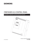
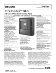
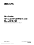
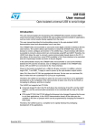
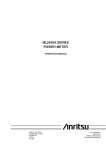
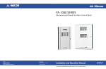
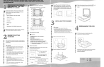
FireSeeker Model FS-250C
Addressable Fire Alarm Control Panel
• One intelligent signaling line circuit (DCLB + DCLA)
• SureWire Polarity insensitive loop wiring
• Utilizes S-Series detectors and devices
• Supports up to 252 addressable inputs and signal/relay
outputs
• Devices operate on standard wire, no twist or shield
required
• FirePrint application specific fire detection
• 4 Class B/2 Class A signal circuits
• Up to 6 amps of signal power
• Built in strobe synchronization protocol
• One man walk test (silent or audible)
• 80 Character backlit LCD display & 20 Zone/4 signal circuit
LED annunciation on Front Panel
• Optional internal DACT capable of transmitting point or
group information
• Programmable from front keypad or Windows based PC
configuration tool
• Single stage and 2-stage operation
• Alarm, pre-alarm, supervisory, trouble
• Auto program feature makes system start-up faster
• Maintenance and technician level passwords
•
ULC Listed
The FS-250C addressable fire alarm control panel is a
small, low cost fire alarm panel suited for stand-alone
operation in small to medium sized facilities. It features a
single addressable input device circuit and four notification
appliance circuits. The FS-250C is ULC Listed.
Main System
The FS-250C indicates alarm, trouble and supervisory
conditions with an 80 character backlit LCD display, as
well as a 20 zone/4 signal LED annunciator that is built in
to the Front Panel. Acknowledge, alarm silence and
system reset are accomplished with built-in membrane
control buttons. Basic user and maintenance level
functions such as viewing history or system enable/
disable are also accomplished through the membrane
control buttons. Password protection of maintenance
level functions is present. The main system can charge
up to 32 AH battery sets, up to 12 AH will fit inside the
enclosure.
The basic FS-250C features a single addressable signaling
line circuit (Class A or B) capable of supporting up to 252
addressable input devices, whether they are detectors,
manual pull stations, or contact monitoring points. Each
detector can also have an optional audible detector base,
relay detector base, or remote lamp associated with it.
These auxiliary devices are completely controlled through
logic and are not required to activate simultaneously with
the detector.The system also has four class B or 2 class
A Notification Appliance Circuits built into the main board.
Each circuit has a capacity of 1.5 amps of 24 VDC for
powering horns, strobes, chimes, and other notification
appliances. The total base system capacity for the four
circuits in 3.0 amps and can be expanded to 6A. Each
signal circuit is fully programmable and supports standard
and custom coded outputs of audible devices. Systems
can be configured to sound different codes on the same
signal circuit to indicate different conditions.
The FS-250C has four Form C relays on the main board
for monitoring alarm, pre-alarm, supervisory and trouble
conditions. Each relay is rated at 1 amp @ 28VDC.
Auxiliary 24VDC power is also available on the main
board, with a capacity of up to 0.4 amps.
CATALOG NUMBER
4306C
The Loop
Programmable Relays
The FS-250C utilizes the advanced CX-2 protocol for
the detection circuit.The CX-2 loops features include
SureWire™ technology providing, 252 addresses (inputs
AND outputs), polarity insensitivity, response time under
3 seconds, retrofit installations using almost any type of
wire (shielded, non-shielded, twisted, etc.)
Programmable relays are available on the FS-250C. A
remote processor board communicates with the main
system board via an RS-485 communication network.
This processor board controls a relay board mounted
adjacent to it. The relay board has eight Form C relay
contacts, rated at 1 amp @ 28VDC maximum. Mode
l FS-RU relay unit contains one processor board and one
relay board to add eight relays to an FS-250C system.
Each processor board can support up to three relay boards
simultaneously, for a total of 24 programmable relay per
processor board. Additional relay extender boards are
available as Model FS-RE8. A total of eight processor
boards (including serial annunciator processor boards) can
be supported simultaneously by the FS-250C. All programmable relay processors and modules can be
mounted in a Model FS-AE accessory enclosure.
You can install an FS-250C using any of the S-series CX-2
devices including the SFP-11 FirePrint™ detector. But we
also offer a new low-cost SFPO-11 detector that is a nonFirePrint photoelectric device for the less-demanding,
more cost-competitive applications.
If you require two detector accessories, such as a relay or
audible base AND a remote lamp, you can install the new
ILED-SC or ILED-SW Intelligent Remote L.E.D. that can
be programmed to mimic the detector L.E.D. or can
respond to panel logic (see ILED installation or catalog
sheet for details.)
Optional Modules
Remote LCD Annunciator
The FS-250C supports a remote LCD display called
the FS-RD2-C. This remote display uses the same 80
character backlit LCD display found on the main system
panel. The FS-RD2-C communicates with the main
system board via an RS-485 communication network. Up
to 15 FS-RD2-C remote displays can be supported on a
single FS-250C system. The FS-RD2-C mounts in a RDCAB enclosure, and the plate on the display is suitable for
flush mounting.
Remote LED Annunciator
The FS-250C also supports a 20 zone/4 signal circuit LED
annunciator called the FS-RA-C. The FS-RA-C LED
annunciator is capable of annunciating alarm, trouble and
supervisory conditions for up to 20 zone/4 signal circuits.
The FS-RA-C has buttons for reset, alarm silence and
acknowledge, up to 15 FS-RA-C’s may be added to a
system. The FS-RD2-C mounts in a RD-CAB enclosure,
and the plate on the display is suitable for flush mounting.
Digital Alarm Communicator Transmitter
(DACT)
Communication between the FS-250C and a monitoring
station is accomplished with the Model FS-DACT Digital
Alarm Communication Transmitter. The FS-DACT supports
two lines and four accounts and can transmit serial
information by point to the Central or Remote station.
Communication protocols available included SIA DCS 8,
SIA DCS 20, Ademco Contact ID, 3/1 1400 Hz, 3/1 2300
Hz, 4/2 1400 Hz and 4/2 2300 Hz. The FS-DACT mounts
within the FS-250C enclosure on an 8-pin connection
point on the main board. No external enclosure is required
and no wires are required between the panel and the
dialer. Programming of account and dialing information is
done as part of the system configuration. No external
programmer for the dialer is required.
Programmable Serial Annunciator Drivers
Programmable serial annunciator drivers are available on
the FS-250C. A remote processor board communicates
with the main system board via an RS-485 communication network. This processor board controls a serial
annunciator driver board mounted adjacent to it.The driver
board has sixteen outputs for LEDs. All serial annunciator
outputs are supervised. Model FS-SAU-2 serial annunciator unit contains one processor board and one serial
annunciator driver board to add 16 LED drivers to an
FS-250 system. Each processor board can support up to
four additional driver boards simultaneously, for a total of
64 programmable serial annunciator drivers per processor
board. Additional serial annunciator extender boards are
available as Model FS-SAE 16. A total of eight processor
boards (including relay processor boards) can be supported simultaneously by the FS-250C.
Programming/Configuration Options
Configuration of the FS-250C can be accomplished in two
ways.The operator interface includes a 16 button keypad.
This keypad can be used to configure all system parameters, including custom messages and logic, right at the
panel with no other configuration tools. Alternately, the
Model FS-CT2 configuration tool can be used on a laptop
computer to upload, download and edit the system
configuration.The Model FS-CT2 configuration tool
includes a connection cable for use between the FS-250C
and a 9-pin serial connection, and the FS-CT2 software.
Use of the FS-CT2 software requires a computer running
Windows 98, Windows 2000, or Windows XP. The FSCT2 tool can be used to generate configuration reports
and download and print history.
If an alarm or other system event occurs during system
configuration, the event will cause the panel to annunciate
the alarm and operate the appropriate outputs.
Custom messages for system addresses consist of two
lines of twenty characters each.The characters include
both upper and lower case letters as well as numbers,
punctuation marks and control characters.This forty
character custom message will be displayed for all events
at that address.
s
Fire Safety
TXL-1008K
Fire Alarm Control Panel
ENGINEERS AND ARCHITECTS SPECIFICATIONS
FEATURES
• 8 Class B (Style B) Initiating Circuits which may be
configured as 4 Class A (Style D) Circuits.
• Expandable up to 24 Class B or 12 Class A Initiating
Circuits
• 4 Class A/B (Style Z/Y) Indicating Circuits with individual
trouble indicators (1.7 Amps max. per circuit)
• Each Indicating Circuit can be configured as Silenceable
or Non-Silenceable. Audibles may be configured as
Steady, Temporal Code, California Code or March Time
• Each Initiating Circuit can be configured as Alarm,
Supervisory, Waterflow or Trouble
• Two LEDs per Initiating circuit; one for Trouble and one
for Status
• Initiating and Indicating Circuits may be individually
disconnected by a DIP switch
• Configurable Signal Silence Inhibit, Auto Signal Silence,
Two-Stage Operation and One Man Walk Test
• Alarm Verification on Initiating Circuits
• Subsequent Alarm, Supervisory and Trouble operation
• Two outputs for 4 wire resettable smoke power supply
•
•
•
•
•
(200 mA Max. each)
Auxiliary relay contacts for Common Alarm and Common
Supervisory as well as a Common Trouble
Relay (Each relay contact Form C, 28 VDC @ 1 Amp
(resistive)
RS-485 Interface for RA-1000 Remote Multiplex
Annunciators
Interface for Remote Trouble Indicator
Easy configuration via push buttons and DIP switches on
the front panel
Description
The Siemens TXL-1008K Fire Alarm Control Panel is a
microprocessor based unit designed for maximum flexibility
and easy installation. Fully configurable from the front panel using the push buttons and DIP switches, it enables the
user to configure the system to meet their specific
requirements.
•
•
•
•
Extensive Transient Protection
6 Amp Power Supply
Removable door for easy installation and servicing
ULC Listed
OPTIONAL FEATURES
• TDACT-100 Digital Communicator
• Polarity Reversal and City Tie Module
• Semi-Flush mounting available with use of optional trim
ring (TXL-1024TR)
The TXL-1008K consists of one TMCC-1024-6 Main
Chassis in a TBB-1024 Enclosure. The TMCC-1024-6 Main
Chassis comes complete with 8 Class B (Style B) Initiating
Circuits which may be configured as 4 Class A (Style D)
Circuits. It can be expanded up to 24 Class B or 12 Class
A circuits with the addition of the TDM-1008 Initiating Circuit
Module. In addition it comes equipped with 4 Class A/B
(Style Z/Y) Indicating circuits which are each rated at 1.7
Amps.
CATALOGUE NUMBER
Siemens Building Technologies, Ltd.
10121
Description
Application
The Main Chassis also includes a 6 Amp Power Supply
which powers the system and supplies two 4-wire resettable
regulated smoke power supply of 24 VDC 200mA maximum
each. The MCC-1024-6 also allows for the addition of two
TSGM-1004 Signal Modules or two TRM-1008 Relay
mdoules in place of the TDM-1008 Initiating Circuit Adder
Modules. (Maximum of 3 Adder modules)
The Siemens TXL-1008K is designed as an economical
Microprocessor Based Fire Alarm Control Panel which is
expandable up to 24 display points. Its modular design
suits various applications. Ideal for applications such as
small institutional and commercial buildings, shopping malls,
offices and public establishments, the TXL-1008K is
configurable to meet virtually all requirements.
The cabinet is available in a beige colour. A Fire Retardant
Lexan Window in the hinged door allows for viewing of the
status LEDs. It comes with a durable CAT-30 lock and
key. Space is provided for up to 17 AH Gel Cell batteries.
The panel is designed to be easy in its installation, operation
and maintenance. This makes the system cost effective and
very reliable for its intended applications.
Ordering Information
Model
Description
Part Number
Basic System Package
TXL-1008K
Microprocessor Based Fire Alarm Control Panel expandable up to 24 display
500-547800
points. Includes TMCC-1024-6 Main Chassis complete with 8 Class B (Style B)
or 4 Class A (Style D) Initiating Circuits, 4 Class A/B (Style Z/Y) Indicating
Circuits, 6 Amp Power Supply and one TBB-1024 Black Enclosure. 500-547800
TXL-1024TR
Semi-Flush Trim Ring
500-647827
Adder Modules
TDM-1008
Eight Class B (Style B) or Four Class A (Style D) Initiating Circuit Module.
TSGM-1004
Four Class A/B (Style Z/Y) Indicating Cct Module (Rated at 1.7 Amps per cct)
TRM-1008
Eight Relay Circuit Module c/w eight Form C relays (Rated for 28 VDC @
1 Amp. max. per relay)
Auxiliary Modules
TDACT-100
Digital Alarm Communication Transmitter/Dialer Module (Requires CFG-100)
TPR-100
Polarity Reversal and City Tie Module.
TCFG-100
Configuration and Diagnostics Tool for TDACT-100.
Remote Annunciators
TRAM-1032
Main Annunciator Chassis c/w Common Control Features, Indicators and
32 Bi-Coloured LEDs.
TRAM-1016
Main Annunciator Chassis c/w Common Control Features, Indicators and
16 Bi-Coloured LEDs.
TRAX-1048
Adder Annunciator Chassis c/w 48 Bi-Coloured LEDs.
TBB-1001
Annunciator backbox with keylock door (Houses one module).
TBB-1002
Annunciator backbox with keylock door (Houses two modules).
TBB-1003
Annunciator backbox with keylock door (Houses three modules).
Siemens Building
Technologies, Ltd.
Fire Safety
Fire Safety
8455 - 19e Avenue
Montreal, Quebec. H1Z 4J2
Tel: (514) 725-1025
Fax: (514) 725-0562
Fire Safety
2 Kenview Boulevard
Brampton, Ontario. L6T 5E4
Tel: (905) 799-9937
Fax: (905) 799-9858
500-847811
500-847812
500-847813
500-847809
500-847808
500-747830
500-347822
500-347824
500-347823
500-647820
500-647821
500-647825
January 2006
Supersedes all previous issues
s
Fire Safety
TXL 1000
FIRE ALARM SYSTEM
ENGINEERS AND ARCHITECTS SPECIFICATIONS
Standard Features
• Large system capacity
• Modular design
• Each Indicating Circuit can be configured as
Silenceable or Non-Silenceable
• Audibles may be configured as Steady, Temporal
Code, California Code or March Time
• Each Initiating Circuit can be configured as Alarm,
Supervisory, Waterflow or Trouble
• Two LEDs per Initiating circuit; one for Trouble and
one for Status
• Initiating and Indicating Circuits may be
individually disconnected by a DIP switch
• Configurable Signal Silence Inhibit, Auto Signal
Silence, Two-Stage Operation and One Man Walk
Test
• Subsequent Alarm, Supervisory and Trouble
operation
• Two outputs for 4 wire resettable smoke power
supply (200 mA Max. each)
• Auxiliary relay contacts for Common Alarm and
Common Supervisory as well as a Common
Trouble Relay (Each relay contact Form C, 28
VDC @ 1 Amp (resistive)
• RS-485 Interface for TRA-1000 Remote Multiplex
Annunciators
• Interface for Remote Trouble Indicator
• Easy configuration via push buttons and DIP
switches on the front panel
• Fully site or field programmable Indicating Circuits
and Auxiliary Relays
s
s
TXL-1000
TXL-1000
•
•
•
•
•
Extensive Transient Protection
Slide-in labels for zone identification
6 Amp or 12 Amp power supplies available
Removable door for easy installation and servicing
Removable terminal blocks for easy wiring and
servicing
• ULC Listed
Optional Modules
• TUDACT-100 Universal Digital Communicator
• TDACT-100 Digital Communicator
• Polarity Reversal and City Tie Module
• Two sizes of Surface mounted cabinets
• Semi-Flush mounting available with use of
optional trim rings
Description
Siemens TM Series 1000 Microprocessor Based Fire Alarm
Control Panels are Multi-Zone units designed for maximum
flexibility and easy installation and operation. Fully
configurable from the front panel using push buttons and
DIP switches, the TXL 1000 enables the user to configure
the system to meet their specific requirements. With a large
capacity of supervised Class A (Style D) or Class B (Style
B) Initiating Circuits and supervised Class A (Style Z) or
Class B (Style Y) Indicating Circuits, the
TXL 1000 is designed to meet virtually all applications.
The TXL 1000 consists of a Main Fire Alarm Chassis which
houses and controls all other modules. Additional modules
may be installed to configure the system to meet any
requirements that the user may have. The TXL 1000 allows
for additional Indicating Circuit, Initiating Circuit and Relay
modules to be added to the system. In addition it allows for
optional modules such as the TDACT-100 Digital
CATALOGUE NUMBER
Siemens Building Technologies, Ltd.
10125
Communicator and the TPR-100 Polarity Reversal / City
Tie Module.
Equipped with Configuration DIP Switches on the Main
Display Module the TXL 1000 Fire Alarm Control Panels
are configured through a combination of DIP switch and
button settings. Through this configuration method the
user can define the system as a Single Stage or Two
Stage operation as well as perform various functions such
as a One Man Walk Test.
System Components
TECH-1048
Expander Chassis provides space for up to six adder
modules of any type. The chassis comes with expander
cables to connect to the main chassis. Used only in the
BB-1072 cabinet.
TRM-1008
8 Relay Circuit Module provides the Series 1000 system
with 8 individual configurable relays per module. Each
relay provides one Form C contact rated at 28 VDC @ 1
Amp (resistive load).
TMCC-1024-6
Main Chassis comes complete with 8 Class B (Style B)
or 4 Class A (Style D) Initiating Circuits, 4 Class A/B (Style
Z/Y) Indicating circuits, a common control and zone
identification display board for up to 24 points and a 6
Amp Power Supply which charges 10-24 AH batteries.
It is expandable with up to two adder modules of any
type plus one of a TDACT-100 Digital Communicator or
TPR-100 Polarity Reversal/City Tie Module.
TDM-1008
8 Initiating Zone Module provides 8 Class B (Style B) or
4 Class A (Style D) Initiating Circuits configurable to
Alarm, Supervisory, Waterflow or Trouble zones.
TSGM-1004
4 Indicating Zone Module provides 4 Class A/B (Style Z/
Y) Indicating Circuits configurable as Silenceable or NonSilenceable. Each Indicating Circuit is rated at 1.7 Amps.
TPR-100
Polarity Reversal & City Tie Module provides the system
with a supervised City Tie (24 VDC/200 mA max.) and
Polarity Reversal connection (24 VDC (open circuit), 8
mA max. (shorted).
TDACT-100
Digital Alarm Communicator Transmitter/Dialer Module
allows the TXL 1000 to use a phone line to call a Central
Station and report an Alarm, Trouble or Supervisory
condition. It uses the Ademco Contact ID and SIA-DCS
protocols.
TMCC-1024-12
Main Chassis comes complete with 8 Class B (Style B)
or 4 Class A (Style D) Initiating Circuits, 4 Class A/B (Style
Z/Y) Indicating circuits, a common control and zone
identification display board for up to 24 points and a 12
Amp Power Supply which charges 17-40 AH batteries.
It is expandable with up to two adder modules of any
type plus one of a TDACT-100 Digital Communicator or
TPR-100 Polarity Reversal/City Tie Module.
TUDACT-100
Digital Alarm Communicator Transmitter/Dialer Module
allows the TXL 1000 to use a phone line to call a Central
Station and report an Alarm, Trouble or Supervisory
condition per zone. It uses the Ademco Contact ID and
SIA-DCS protocols.
TBB-1024
TBB-1072
This enclosure is capable of handling one TMCC-1024-6
or TMCC-1024-12 Main Chassis and up to 17 AH
Batteries. The TXL-1024TR Semi-Flush Trim Ring is
required for flush mounting. The cabinet features a lock
and a removable door for easy installation and servicing.
The cabinet is available in a black colour.
This enclosure is capable of handling one TMCC-1024-6
or TMCC-1024-12 Main Chassis and one TECH-1048
Expander Chassis as well as up to 40 AH Batteries. The
TXL-1072TR Semi-Flush Trim Ring is required for flush
mounting. The cabinet features a lock and a removable
door for easy installation and servicing in a black exterior.
s
s
s
TXL-1000
TXL-1000
TXL-1000
The TRA-1000 Series Remote Multiplex Annunciators
The TRA-1000 Series Remote Multiplex Annunciators have been designed to compliment the TXL 1000 Fire Alarm
Control Panels. Comprised of four chassis models, the TRA-1000 Annunciators provide a large capacity of annunciation
(up to 224 display points). The TRA-1000 Series Remote Multiplex Annunciators consist of sealed membrane-like buttons
and LED indicators which are automatically configured to match the TXL 1000 Fire Alarm Control Panel configuration.
The TRA-1000 Series come standard with Bi-Coloured LEDs to annunciate Alarm or Supervisory points. Each display
point comes with slide-in labels for point identification. Three annunciator enclosure backboxes are available. The enclosures
are available in a black colour.
FireFinder XLS
FireFinder XLS Fire Alarm Control Panel
• Standard 2500 addressable point
capacity system
• Networkable to other FireFinder XLS
systems
• Powerful, easy-to-use programming
capabilities
• Fully Field Programmable Via Windows
Laptop Computer
• 6" Backlit LCD display
• User-friendly system interface
• Touch screen for maintenance
operations and function keys
• Multi-Language Display
• Universal AC power input - 120/
240VAC, 50/60Hz
• 12 amps of system power, expandable
to 48 amps
• Numerous Relays - alarm, trouble,
programmable…
• SureWire addressable loop technology
• Polarity insensitive detection circuits
(Patented)
• Useful diagnostic LEDs on all cards
• Supports FirePrint application specific
detection
• Security Device Monitoring
• Sprinkler Supervision
• Intelligent/Analog Detection Circuits,
style 6 (Class A) or Style 4 (Class B)
• Detector Sensitivity Readout/Printout
per NFPA 72
• Degrade mode operation
• Distributed Processing
• Supervised Remote Printer
• 32 Character Custom messages
• UUKL Listed for Smoke Control
•
UL, ULC Listed, FM, CSFM, &
NYMEA Approved
• Multiple Command Stations
• Menu Driven Operator Commands
• 5000 Event History Logging with
On Line & Off Line Reports
• User Help Screens
• Multiple Levels of Password
Protection
• Automatic Environmental
Compensation for Smoke Detectors
• Alarm verification by Device or Zone
• Logic Controlled Output Functions
• Time Based Controlled Output
Functions
• Holiday Schedule
• City Tie/Leased Line
• Coded Outputs
• 200 notification appliance circuits
capacity
• Up to 4.0 amps (24VDC) per NAC
• Built-in strobe synchronization
protocol
• Supports Pre-Action, Deluge and
agent releasing
• Voice evacuation system optional
• Modular assembly
• NEC 760 Power Limited Circuits (UL
864 Compliant)
• Intelligent Interface to Building/
Process Management Systems
• Operates as Interactive Peer with
other XLS or XLSVs in a XNET
network
• Pre-Alarm Operation
• Supports Single Person Test, “Walk Test”
• NCCG Graphics support
Introduction
FireFinder XLS is a microprocessor based advanced life
safety system. Its 6" display and large lighted buttons
makes it the most intuitive fire alarm user interface in the
industry. Its use of the unique multiprocessor "Network"
design along with its ability to utilize both analog and
conventional detection devices make it an extremely
flexible and configurable life safety system.
The XLS is ideally suited for commercial, institutional and
industrial fire detection and notification applications. It
complies with the requirements of NFPA Standard 72 and
is listed by Underwriters Laboratories under their standard
UL-864. Underwriter's Laboratories of Canada also lists it
for fire applications under ULC-S527. It is approved by
Factory Mutual as well as CSFM and NYMEA for use in
those specific locales.
In addition to the standard fire applications, XLS is listed
by Underwriters Laboratories under the category UUKL for
smoke control. XLS can be used as a listed Fireman's
Smoke Control Station in high-rise office buildings, malls
and other large structures.
XLS is listed by UL and approved by FM for releasing
Halon 1301, Sinorix clean agent systems and pre-action or
deluge sprinkler systems. These include foam or water
applications. XLS follows the releasing requirements
specified in the NFPA 12 Standards 12A, 13 and 2001.
CATALOG NUMBER
6300
Description
The basic XLS control unit consists of the following
subassemblies: PMI Person Machine Interface; PSC-12
Power Supply; DLC Device Loop Card; ZIC-4A Zone
Indicating Card; CC-5 Card cage; ID-SP Inner Door Blank
Single Plate; CAB-1, CAB-2 or CAB-3 enclosures. Optional modules that can be installed with the XLS System
include: CC-2 Card Cage; NIC-C Network Interface Card;
ZIC-8B/ZIC-2C Zone Indicating Card 8 circuits; CRC-6
Control Relay Card; OCM-16 Output Control Module;
SCM-8 Switch Control Module; LCM-8 LED Control
Module; FCM-6 Fan Control Module; SIM-16 Supervised
Input Module; PSX-12 Power Supply Extender; RNI Remote Network Interface; RPM Remote Printer Module;
SSD System Status Display; MDACT Multi-Point Digital
Alarm Communicator; REMBOX2 Two Module Remote
Enclosure; REMBOX4 Four Module Remote Enclosure.
The XLS panel is compatible with a full line of intelligent
initiating devices highlighted by the FirePrint Application
Specified Detectors, models HFP-11 and HFPT-11. It is also
compatible with the NCC series of graphics command
centers.
The FireFinder system is controlled and operated from the
PMI. The intuitive person machine interface uses large
lighted buttons to prompt users as to the next correct
system operation that is available (Acknowledge, Silence,
Unsilence Audible or Reset).
DLC Device Loop Card
DLC Device Loop Card
The DLC Device Loop Card is the interface for connection
with FireFinder XLS detectors and initiating devices
including manual stations, control and input devices. The
DLC plugs into one slot of the CC-2 or CC-5 card cage.
Programming the DLC is accomplished using the
FireFinder XLS Zeus configuration tool. The DLC takes one
address on the network and communicates with two
device circuits with a total of up to 252 detectors and
devices. The DLC has 12 LEDs for diagnostic purposes
and provides ground fault detection and zone isolation
circuitry.
PMI Person Machine Interface
PMI Person Machine Interface
The Person Machine Interface is the heart of the FireFinderXLS system. The PMI serves as both operator interface
and central microprocessor for the system. From the PMI
the user can acknowledge events, control the system
notification appliance circuits and reset the system.
Detailed information about the nature and location of the
events can also be displayed.
The PMI contains the site-specific program configuration created in the Zeus tool. The controller in the PMI provides
all system logic and supervision.
The PMI contains a large 6" (1/4 VGA) monochrome LCD
display, touch screen and LED's for displaying system
status. An audible sounds when there are unacknowledged
events on the PMI. The display is surrounded by keys that
are used to control the displayed information and to
navigate through these screens. Keys are also provided to
obtain "Help" and to enter into the menu features of the
PMI.
ZIC-4A Zone Indicating Card
ZIC-4A Zone Indicating Card
The Zone Indicating Card ZIC-4A provides four fully supervised programmable output circuits for use on the
FireFinder XLS Fire Alarm Control Panel. The ZIC-4A
supplies four Class B (Style Y) or Class A (Style Z) type
output circuits, power limited to 4.0 amps maximum per
circuit. Each circuit can be independently programmed for
use with listed audible or visual notification appliances,
listed emergency audio speakers, municipal tie boxes,
leased lines, or as releasing circuits. The ZIC-4A plugs into
one slot in the CC-5 or CC-2 Card Cage, and has on-board
LEDs for system status and troubleshooting. Indication of
power, communication, internal operation, and ground fault
conditions are provided, as well as indication of circuit
activation or trouble conditions.
The NIC-C Card has diagnostic LEDs that indicate Card Fail,
CAN Fail, HNET Fail, XNET Fail, Ground Fault, Loop A Fail
and Loop B Fail, as well as LEDs to indicate Power, Style
and Active Networks.
ZIC-8B/ZIC-2C
ZIC-8B/ZIC-2C
The Zone Indicating Card ZIC-8B provides eight fully
supervised programmable output circuits for use on the
FireFinder XLS Fire Alarm Control Panel. The ZIC-8B
supplies 8 Class B (Style Y) type output circuits, power
limited to 2.0 amps maximum per circuit. Each circuit can
be independently programmed for use with listed audible
or visual notification appliances, or listed emergency audio
speakers. The ZIC-8B plugs into one slot in the CC-5 or
CC-2 Card Cage, and has on-board LEDs for system status
and troubleshooting. The ZIC-2C mounts directly on the
ZIC-8B, and allows each of the ZIC-8B output circuits to be
used for 2-channel voice applications. Indication of power,
communication, internal operation, and ground fault
conditions are provided, as well as indication of circuit
activation or trouble conditions.
HLIM Line Isolator Module
HLIM Line Isolator Module
The HLIM loop isolator module provides short circuit
protection on FireFinder XLS intelligent device circuits
(DLC). When a short is detected by the HLIM, it isolates
the affected segment of the circuit, allowing the remaining
devices to continue operation.The HLIM is self-restoring,
automatically reconnecting to circuit segment when the
fault is removed.
It can be wired in either a Style 4 or Style 6 configuration.
The HLIM does not occupy a device address on the DLC
circuit and requires no programming. Up to fifteen HLIMs
may be installed on each DLC loop.
HCP
NIC-C
NIC-C
The Model NIC-C Network Interface Card provides HNET or
XNET network communications between enclosures. In
addition to the HNET or XNET communication the NIC-C
provides CAN network communication within an enclosure
or external to the enclosure. The HNET or XNET can be
wired Style 4 or Style 7. The CAN network can be wired
Style 4 only.
When the NIC-C is used for HNET communications it
provides communication between enclosures on a single
system.
When the NIC-C is used for XNET communications it
provides communication between systems. The maximum of XNET NIC-Cs on a single system (single node) is
one, for a total of 64 XNET NIC-Cs on a Peer-To-Peer
Networked System.
HCP
The HCP provides an intelligent control point for the
FireFinder XLS Control Panel. The HCP can be
programmed as an independent, remotely located telephone zone, speaker zone or notification appliance circuit.
The HCP is designed to be used with the Siemens Fire
Safety notification appliance product line.
The HCP communicates through the DLC analog loop and
can be wired either Class A (Style Z) or Class B (Style Y).
The 24 VDC power input comes from either the control
panel or from any UL listed power limited, auxiliary power
supply.
rooms. Also, the CDC-4 can be used to upgrade Siemens
conventional fire alarm panels to the FireFinder XLS
system without requiring detector replacement.
CRC-6 Controllable Relay Card
CRC-6 Controllable Relay Card
The Controllable Relay Card (Model CRC-6) is used with
the FireFinder XLS Fire Alarm Control Panel. It is designed
to provide auxiliary control of building functions such as
door holder release, elevator capture, smoke control, lock
release, etc. The CRC-6 plugs into one slot in the CC-5 or
CC-2 Card Cage. It provides six fully programmable relays.
Each relay contains one set of SPDT contacts rated at 4
Amps 30 VDC/120 VAC resistive and 3.5 amps 120 VAC
inductive (0.6 P.F.).
SIM-16 Supervised Input Module
SIM-16 Supervised Input Module
The SIM-16 Supervised input Module is a remotely
located, general-purpose input module. It provides sixteen
input circuits for remote system monitoring. Each input
can be individually programmed as supervised (dry contact
only) or unsupervised (general purpose input.) The SIM-16
has two Form C relays. The relays and inputs are programmed using the Zeus system programming tool.
CC-2 Card Cage-2 Slots
CC-5 Card Cage-5 Slots
CC-5/CC-2 Card Cages
The CC-5/CC-2 card cages provide the physical mounting
location and all wiring connection points for all fire and
voice system options cards for the FireFinder-XLS system.
The CC-5 has 5 slots and the CC-2 has two slots.
All cards plugged into the CC-5/CC-2 card cage communicate with other FireFinder-XLS modules via a common data
bus. Connectors are provided on the left & right side of the
CC-5 to connect a (60) pin cable for communications with
the FireFinder-XLS's operator interface, power supplies and
amplifiers modules.
All field wiring to devices and circuits terminates on the
CC-5/CC-2 card cage. All cards designed for use with the
CC-5/CC-2 route their field wiring terminations to the "top"
of the CC-5/CC-2. These connections are all power limited.
Internal wiring connections distribute 24VDC to cards or
high level audio signals (depending on application used)
connect to the "bottom" of the CC-5/CC-2. These connections are all non-power limited.
All wiring connections to the CC-5/CC-2 are to removable
terminal blocks. Terminal blocks are rated for use with wire
sized 12AWG to 24AWG. Each connector is numbered to
make wiring terminations to the correct position on the
terminal block simple and reduce the potential for wiring
errors.
SCM-8
CDC-4
CDC-4
The Model CDC-4 Conventional Detector Card is used to
monitor Siemens Fire Safety conventional detectors on the
FireFinder XLS system. The CDC-4 can be used in applications where conventional detectors are more suited than
addressable detectors, like hallways or large meeting
SCM-8 Switch Control Module
The SCM-8 is a FireFinder XLS option module which
provides manual control of the Emergency Voice Evacuation System or manual fire system control. Each SCM-8
module provides eight momentary pushbutton switches
and 16 LED's to indicate their status. Each switch is
assigned two LED's and a label to indicate the switch's
programmed usage. The label slides behind a clear
protective membrane. One of the LED's assigned to each
switch is a dual color LED used to indicate what type of
signal is active.
indicate Fan/Damper/Motor status: OFF (Red LED), ON
(Green LED), TROUBLE(Yellow LED).
Each SCM-8 and each switch is fully programmable and
may be used to control speaker circuits, and awide range
of general system functions such as All Call, All Evac,
Warden's Page, Speaker, etc. Anynumber of circuits may
be grouped and controlled bya single switch. Switch
usages and zone groupings are assigned using the ZEUS
system programmingsoftware.The SCM-8s are mounted
on a hinged panel as a partof the FireFinder XLS Command
Console enclosure.
PSC-12 Power Supply Charger Module
LCM-8
LCM-8 LED Control Module
The LCM-8 is an FireFinder XLS option module which
provides LED annunciation of system activity. Each LCM8 module contains eight groups of 2 LED's, each of which
can be assigned to desired outputs using the ZEUS
programming software. Eight LED's are dual color capable
of being lighted either RED or GREEN flashing or steady.
The remaining LED's are AMBER flashing or steady. A
space is provided for labeling of LED functions. The label
slides behind a clear protective membrane. The LCM-8
dimensions are identical to the SCM-8 and is mounted on
the same hinged panel as a part of the FireFinder XLS
Command Console enclosure.
PSC-12 Power Supply Charger Module
The PSC-12 is a high current power supply that provides
the FireFinder-XLS primary regulated 24VDC power to
operate. It is rated at 12Amps (Alarm)/5Amps (Standby)
and has a built in battery charger capable of charging up to
100AH batteries. The PSC-12 is an addressable intelligent
microprocessor controlled module that communicates it
status to the system operator interface (PMI). The PMI is
able to query the status of the power supply to obtain
information regarding system charging current, terminal
loading information, ground fault conditions and more.
PTB Power Termination Board
PTB Power Termination Board
The PSC-12 comes packaged with a module called the
PTB. The PTB is the Power Termination Board and is
required for operation with the PSC-12. The PTB filters the
power from the incoming AC mains and distributes it to
the PSC-12 power supply and the optional PSX-12 power
supply extender.
FCM-6
FCM-6 Fan, Motor, dampers Control Module
The FCM-6 is an FireFinder XLS command console option
module that provides manual control of building HVAC
system fans, motors, and dampers. EachFCM-6 module
provides (6) sets of (3) push button switches for manual
system control. Each switch has3 associated LEDs to
The PTB has an optional connector that can be used during
system installation, commissioning & service to provide
the technician with a place to plug in their laptop computer
if required. The AC-ADPT is an optional accessory cable
that allows connection on one side to the PTB via a keyed
connector and on the other end directly into to the laptop's
transformer. Most laptop computer external power transformers have removable AC power cords which can be
replaced by the AC-ADPT to temporarily provide an AC
power source for laptop computer used during system
installation, service and maintenance calls when needed.
SSD Series
PSX-12 Power Supply Extender
PSX-12 Power Supply Extender
The PSX-12 is a high current auxiliary power supply that
expands the FireFinder-XLS systems main PSC-12 power
supply and battery charger with an additional 24VDC
power. It is rated at 12Amps.
RNI Remote Network Interface
RNI Remote Network Interface
The Model RNI Remote Network Interface provides a
connection point for use with equipment mounted in a
remote lobby enclosure on the FireFinder XLS Fire Alarm
Control Panel. It is used to provide additional input, output
and control features to the system remotely from the main
control panel. These additional features may include control
switches and indicators (SCM-8, LCM-8 and FCM-6),
remote emergency paging microphones or telephones
(LVM, FMT), or controls used in graphic annunciators (SIM16, OCM-16) or System Status Display with the ability to
acknowledge alarms, silence audibles and reset the
system (SSD-C-REM). The RNI allows the PMI to be
mounted in the REMBOX2 or REMBOX4 remote lobby
enclosure.
SSD Series
The SSD Series System Status Display is a remote LED/
LCD display that shows the local status of a FireFinder XLS
system. An LED illuminates when alarm, supervisory,
trouble, and security events occur on the system. A fourline LCD will give details of the event in alphanumeric
form. The display can be toggled to display additional
events. Optional remote system control capabilities are
available.
Models SSD-C, SSD-C-INT, and Model SSD-C-REM have
three additional control buttons for acknowledging events,
silencing audible circuits, and resetting the system. The
SSD-C and SSD-C-INT have an integral keyswitch that
enables these control buttons to operate. The SSD-C-REM
is located within a locked cabinet, so no additional
keyswitch is required for enabling the control buttons.
CAB1 Single Row Enclosure
RPM Remote Printer Module
RPM Remote Printer Module
The Model RPM Remote Printer Module provides a means
of connecting the FireFinder XLS system to a printer, like
the PAL-1, for creating a hard copy of system status and
configuration reports. Simultaneously, it provides an
output port that can be configured to communicate with
external systems.
CAB1 Single Row Enclosure
The Model CAB1 is the smallest of the FireFinder XLS
enclosures. It can house a single CAB-MP cabinet mounting plate for mounting card cages, power supplies and bulk
amplifiers. The CAB1 also has four mounting slots on the
inner door for mounting a PMI interface and Model ID-MP
switch module brackets. The CAB1 comes complete with
a black back box, black inner and outer doors, a single lock
and key set on the outer door, a single CAB-MP cabinet
mounting plate (installed), and a single OD-LP outer door
lens plate (installed). A red version called the CAB1-R is
also available. Approximate size is 27" high, 26" wide, and
8" deep.
MDACT - Multi-Point Digital Alarm
Communicator Transmitter
MDACT - Multi-Point Digital Alarm
Communicator Transmitter
The Model MDACT Multi-Point Digital Alarm Communicator Transmitter is used in FireFinder XLS systems where
point identification of alarm, supervisory, security and
trouble events is required at Central or Remote Receiving
Stations. An intelligent RS-485 communications protocol
transmits all system information to the MDACT. The
installer selects the specific events, or groups of events,
that are to be transmitted from the MDACT over phone
lines to listed receiving station equipment. The MDACT
can transmit point information via Ademco Contact ID and
the SIA protocol. For installation, a MOM2-XMP Mounting
Plate, MOM-2 card cage, and an XMI Interface Card are
required.
CAB2 Two Row Enclosure
CAB2 Two Row Enclosure
The Model CAB2 is the mid-sized FireFinder XLS enclosure capable of housing up to two CAB-MP cabinet
mounting plates. The inner door has two rows of four
mounting slots. The outer door has space for mounting
two outer door plates (Models OD-LP, OD-BP or OD-GP).
The outer door can be configured to open from either side.
The CAB2 consists of the CAB2-BB back box, the CAB2BD black inner and outer door package, two CAB-MP
cabinet mounting plates, and one OD-LP lens plate. The
outer door has a single lock and key set installed. A red
version called the CAB2R is also available. Approximate
size is 45” High, 26” wide, and 8” deep.
CAB3 Three Row Enclosure
CAB3 Three Row Enclosure
The Model CAB3 is the largest single FireFinder XLS
enclosure available. It can house up to three CAB-MP
cabinet mounting plates in the enclosure, and three rows
of inner door mounting slots. The outer door can be
configured to open from either side. The CAB3 consists of
the CAB3-BB back box, the CAB3-BD black inner and outer
door package, three CAB-MP cabinet mounting plates, and
one OD-LP lens plate. The outer door has two locks and
key sets installed. A red version called the CAB3R is also
available. Approximate size is 63" high, 26" wide, and 8"
deep.
Enclosure Trim Kits
Trim kits are available for all system enclosures for semiflush mounting applications. The Model CAB1-TK (for black
enclosures) and the Model CAB1R-TK (for red enclosures)
fit the CAB1 and CAB1-R enclosures. Similarly, the
CAB2-TK and CAB2R-TK fit the CAB2 enclosure, and the
CAB3-TK and CAB3R-TK fit the CAB-3 enclosure.
Remote Transponders
The FireFinder XLS system can use remote transponders
for mounting additional modules like amplifiers without
requiring a PMI or any control switches. Special doors are
available for systems using CAB2 or CAB3 remote
transponders. These doors, Models CAB2-XBD and
CAB3-XBD, omit the unused inner door and come complete with ventilation louvers built into the door. The
CAB2-XBD fits on a CAB2-BB and the CAB3-XBD fits on a
CAB3-BB. The CAB2-XBD and CAB3-XBD are supplied in
black. Red versions called the CAB2-XRD and CAB3-XRD
are also available. Complete box and door kits are available
as Model CAB2-X and Model CAB3-X.