1
RuSCSup_EN-5_FM.book Page 1 Tuesday, October 9, 2001 5:04 PM
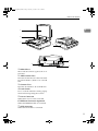
Color Scanner
Setup Guide
ZDLH001E.eps
Read this manual carefully before you use this product and keep it handy for future
reference.
For safety, please follow the instructions in this manual.
RuSCSup_EN-5_FM.book Page 1 Tuesday, October 9, 2001 5:04 PM
Color Scanner Setup Guide
Printed in the Japan
UE USA G412-6653
RuSCSup_EN-5_FM.book Page 1 Tuesday, October 9, 2001 5:04 PM
Introduction
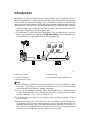
This manual contains detailed instructions on the operation and maintenance of this machine. To get
maximum versatility from this machine all operators should carefully read and follow the instructions in
this manual. Please keep this manual in a handy place near the machine.
Please read the Safety Information before using this machine. It contains important information related
to USER SAFETY and PREVENTING EQUIPMENT PROBLEMS.
Power Source
Color Scanner: 120 V, 60 Hz, 10 A or more
Please be sure to connect the Power Cord to a power source as above.
Two kinds of size notation are employed in this manual. With this machine refer to the inch version.
Important
Parts of this manual are subject to change without prior notice. In no event will the company be liable
for direct, indirect, special, incidental, or consequential damages as a result of handling or operating
the machine.
Caution:
Use of controls or adjustment or performance of procedures other than those specified in this manual
might result in hazardous radiation exposure.
Do not attempt any maintenance or troubleshooting other than that mentioned in this manual. This
scanner contains a laser beam generator and direct exposure to laser beams can cause permanent
eye damage.
Two kinds of size notation are employed in this manual. With this machine refer to the inch version.
Ricoh shall not be responsible for any damage or expense that might result from the use of parts other
than genuine Ricoh parts in your Ricoh office product.
RuSCSup_EN-5_FM.book Page 1 Tuesday, October 9, 2001 5:04 PM
Note to users in the United States of America
Notice:
This equipment has been tested and found to comply with the limits for a Class B digital device, pursuant to Part 15 of the FCC Rules. These limits are designed to provide reasonable protection against
harmful interference in a residential installation. This equipment generates, uses and can radiate radio
frequency energy and, if not installed and used in accordance with the instructions, may cause harmful
interference to radio communications.
However, there is no guarantee that interference will not occur in a particular installation. If this equipment does cause harmful interference to radio or television reception, which can be determined by turning the equipment off and on, the user is encouraged to try to correct the interference by one more of
the following measures:
Reorient or relocate the receiving antenna.
Increase the separation between the equipment and receiver.
Connect the equipment into an outlet on a circuit different from that to which the receiver is
connected.
Consult the dealer or an experienced radio/TV technician for help.
Warning
Changes or modifications not expressly approved by the party responsible for compliance could void
the user's authority to operate the equipment.
Caution (in case of 100BaseTX environment):
Properly shielded and grounded cables (STP) and connectors must be used for connections to host
computer (and/or peripheral) in order to meet FCC emission limits.
Declaration of Conformity
Product Name: Color Scanner
Model Number: Ricoh Aficio Color Scanner IS330DC
Responsible party: Ricoh Corporation
Address: 5 Dedrick Place, West Caldwell, NJ 07006
Telephone number: 973-882-2000
This device complies with part 15 of FCC Rules.
Operation is subject to the following two conditions:
1. This device may not cause harmful interference, and
2. this device must accept any interference received,
including interference that may cause undesired operation.
Properly shielded cables must be used for connections to host computer (and/or peripheral)
in order to meet FCC emission limits.
Network interface cable with ferrite core must be used for RF interference suppression.
Note to users in Canada
Note:
This Class B digital apparatus complies with Canadian ICES-003.
Remarque concernant les utilisateurs au Canada
Avertissement:
Cet appareil numérique de la classe B est conforme à la norme NMB-003 du Canada.
In accordance with IEC 60417, this machine uses the following symbols for the main power switch:
a means POWER ON.
b means POWER OFF.
Ricoh Aficio Color Scanner IS330DC
Copyright © 2000
RuSCSup_EN-5_FM.book Page i Tuesday, October 9, 2001 5:04 PM
Trademarks
Microsoft®, Windows® and Windows NT® are registered trademarks of Microsoft Corporation in the United States and/or other countries.
Other product names used herein are for identification purposes only and might
be trademarks of their respective companies. We disclaim any and all rights in
those marks.
Notes:
Some illustrations might be slightly different from your machine.
Certain options might not be available in some countries. For details, please contact your local dealer.
Note
The proper names of the Windows operating systems are as follows:
• Microsoft® Windows® 95 operating system
• Microsoft® Windows® 98 operating system
• Microsoft® Windows® Millennium Edition (Windows Me) operating system
• Microsoft® Windows® 2000 Professional
• Microsoft® Windows® 2000 Server
• Microsoft® Windows NT® Server operating system Version 4.0
• Microsoft® Windows NT® Workstation operating system Version 4.0
• Microsoft® Windows NT® Server network operating system version 3.51
• Microsoft® Windows NT® work station operating system version 3.51
i
RuSCSup_EN-5_FM.book Page ii Tuesday, October 9, 2001 5:04 PM
Safety Information
When using your scanner, the following safety precautions should always be
followed.
Safety During Operation
In this manual, the following important symbols are used:
R WARNING:
Indicates a potentially hazardous situation which, if instructions
are not followed, could result in death or serious injury.
R CAUTION:
Indicates a potentially hazardous situation which, if instructions are
not followed, may result in minor or moderate injury or damage to
property.
R WARNING:
• Connect the Power Cord directly into a wall outlet and never use an extension cord.
• Disconnect the power plug (by pulling the plug, not the cable) if the power cable or plug
becomes frayed or otherwise damaged.
• To avoid hazardous electric shock or laser radiation exposure, do not remove any covers
or screws other than those specified in this manual.
• Turn off the power and disconnect the power plug (by pulling the plug, not the cable) if
any of the following conditions exists:
• You spill something into the equipment.
• You suspect that your equipment needs service or repair.
• Your equipment's cover has been damaged.
• Disposal can take place at our authorized dealer or at appropriate collection sites.
ii
RuSCSup_EN-5_FM.book Page iii Tuesday, October 9, 2001 5:04 PM
R CAUTION:
• Protect the equipment from dampness or wet weather, such as rain, snow, and so on.
• Unplug the Power Cord from the wall outlet before you move the equipment.
While moving the equipment, you should take care that the Power Cord will not be damaged under the equipment.
• When you disconnect the power plug from the wall outlet, always pull the plug (not the
cable).
• Do not allow paper clips, staples, or other small metallic objects to fall inside the equipment.
• For environmental reasons, do not dispose of the equipment or expended supply waste
at household waste collection points. Disposal can take place at an authorized dealer or
at appropriate collection sites.
• The inside of the machine could be very hot. Do not touch the parts with a label indicating
the "hot surface". Otherwise it could cause a personal burn.
• Our products are engineered to meet high standards of quality and functionality, and we
recommend that you only use the expendable supplies available at an authorized dealer.
Lithium Batteries (Memory Back-up)
R WARNING:
• Do not try to replace the lithium batteries by yourself. A battery of this type can explode
if incorrectly replaced. If the lithium batteries need to be replaced, contact an authorized
dealer to request servicing.
• Never dispose of the lithium batteries by incineration. This can cause them to rupture resulting in injury.
Note
❒ Please return used NIC boards to our authorized dealer or service representative.
Your cooperation with our recycling activities is appreciated.
❒ NIC boards are equipped with a lithium battery. In the case NIC boards are disposed
of by the customer, please dispose them in accordance with national or local regulations after separating the lithium batteries from the NIC board.
iii
RuSCSup_EN-5_FM.book Page iv Tuesday, October 9, 2001 5:04 PM
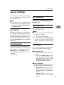
Energy Star Program
As an ENERGY STAR Partner, we have determined
that this machine model meets the ENERGY STAR
Guidelines for energy efficiency.
The ENERGY STAR Guidelines intend to establish an international energy-saving system for
developing and introducing energy-efficient office equipment to deal with environmental issues, such as global warming.
When a product meets the ENERGY STAR Guidelines for energy efficiency, the Partner shall
place the ENERGY STAR logo onto the machine model.
This product was designed to reduce the environmental impact associated with office equipment by means of energy-saving features, such as Low-power mode.
❖ Energy Saver mode
This unit automatically lowers its power consumption at a predetermined
time (approximately 15 minutes) after the last operation was performed. To
operate the unit from this mode, see the instructions below.
• Method for clearing
• Put a document on the Document Tray.
• Open the cover of the Automatic Document Feeder (ADF).
• Open the White Sheet cover.
• Follow the instructions from the PC.
Note
❒ The Energy Saver mode does not work in the following conditions.
• When an optional device is attached.
• When an error occurs.
• When a document is placed on the Document Tray.
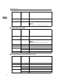
❖ Specifications
Energy Saver mode
iv
Power consumption
Approx. 11W
Transitional interval
15 minutes
RuSCSup_EN-5_FM.book Page v Tuesday, October 9, 2001 5:04 PM
Manuals for This Scanner
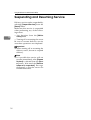
Manuals for This Scanner
The following manuals describe the operational and maintenance procedures of
this machine.
To enhance safe and efficient operation of this scanner, all users should read and
follow the instructions carefully.
❖ Quick Installation Guide
Describes how to install the scanner.
❖ Setup Guide (this manual)
Provides information about setting up the scanner and its options. This manual is provided as a printed manual, and also as a PDF file on the CD-ROM.
❖ Scanner Reference
Provides information about using the scanner. This manual is provided as a
PDF file.
Note
❒ There is a CD-ROM that comes with this scanner.
v
RuSCSup_EN-5_FM.book Page vi Tuesday, October 9, 2001 5:04 PM
How to Read This Manual
Symbols
In this manual, the following symbols are used:
R WARNING:
This symbol indicates a potentially hazardous situation which, if instructions
are not followed, could result in death or serious injury.
R CAUTION:
This symbol indicates a potentially hazardous situation which, if instructions
are not followed, may result in minor or moderate injury or damage to property.
* The statements above are notes for your safety.
Important
If this instruction is not followed, paper might be misfed, originals might be
damaged, or data might be lost. Be sure to read this.
Preparation
This symbol indicates the prior knowledge or preparations required before operating.
Note
This symbol indicates precautions for operation, or actions to take after misoperation.
Limitation
This symbol indicates numerical limits, functions that cannot be used together,
or conditions in which a particular function cannot be used.
Reference
This symbol indicates a reference.
[
]
Keys that appear on the machine's panel display.
Keys and buttons that appear on the computer's display.
{
}
Keys built into the machine's operation panel.
Keys on the computer's keyboard.
vi
RuSCSup_EN-5_FM.book Page vii Tuesday, October 9, 2001 5:04 PM
TABLE OF CONTENTS
.................................................................................................................... 1
1. Getting Started
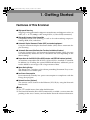
Features of This Scanner.......................................................................... 3
Guide to This Scanner .............................................................................. 4
Understanding the Indicators................................................................... 6
Confirmations Prior to Installation .......................................................... 7
Confirming the Installation Environment ...................................................... 7
Connecting the Power Cord ..................................................................... 9
Connecting to the PC .............................................................................. 10
Connecting to the SCSI Interface................................................................ 10
Connecting to the IEEE1394 Interface (optional)........................................ 11
Installing Options .................................................................................... 13
Installing the IEEE 1394 Board (IEEE 1394 Interface Board Type S)......... 13
Installation of Image Processing Unit
(Image Processing Unit Type A) ............................................................... 14
2. Installing the Scanner drivers
Using Windows98/ME, Windows2000....................................................
Installing the STI Driver...............................................................................
Installing the Scanner Driver by Auto Run ..................................................
Using Windows95, WindowsNT4.0 ........................................................
Using WindowsNT3.51 ............................................................................
Installing the TWAIN driver .........................................................................
About the Software on the CD-ROM ......................................................
List of Files ..................................................................................................
TWAIN Driver ..............................................................................................
ISIS Driver...................................................................................................
17
17
18
20
21
21
22
22
22
23
INDEX........................................................................................................ 24
vii
RuSCSup_EN-5_FM.book Page viii Tuesday, October 9, 2001 5:04 PM
viii
RuSCSup_EN-5_FM.book Page 3 Tuesday, October 9, 2001 5:04 PM
1. Getting Started
Features of This Scanner
❖ High-speed Scanning
Scanning can be performed at 30ppm in monochrome and 10ppm in color. (at
A4L, 8.5” × 11”L/200dpi, when using SCSI-2/3 (Ultra-SCSI) connection)
❖ High-quality Images, Color Compatible
Compatible for full color scanning, as well as for color matching output, including sRGB, ICM, and others.
❖ Automatic Duplex Document Feeder (ADF) as standard equipment
Using the Automatic duplex document feeder (ADF) allows automatic duplex scanning.
❖ Automatic Document Size Detection Function Installed as Standard
Using the Contact Glass and Automatic Document Feeder (ADF), this unit
can automatically detect the size of a document and scan depending on the
driver settings.
❖ Preparations for the SCSI-2/3 (Ultra-SCSI) Interface and IEEE1394 Interface (optional)
An interface compatible with SCSI-2/3 (Ultra-SCSI) is installed as standard.
In addition, by installing the optional IEEE1394 Interface, additional power
can be added to scan images with a large amount of data.
❖ Space Saving Design
This design uses a wingless style without protruding Document Trays to enable effective use of office space.
❖ Low Power Consumption
Environmentally friendly low power consumption in compliance with the
Energy Star program.
❖ Network function (Optional)
The scanner can be shared via the Ethernet (TCP/IP) by using the Network
Interface Kit.
Note
❒ The “L”symbol means short-edge feed direction.
❒ The Network Interface Kit will be commercially available a various times depending on the area. Contact your local dealer about the release information.
3
RuSCSup_EN-5_FM.book Page 4 Tuesday, October 9, 2001 5:04 PM
Getting Started
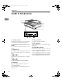
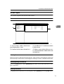
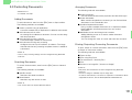
Guide to This Scanner
1
1
2
3
4
5
6
7
8
9
11
ZDLH0
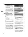
1. Document Tray
8. Rotary Switch
Set the document to be scanned by the
Automatic Document Feeder (ADF).
Used for setting the SCSI ID.
2. Automatic Document Feeder
(ADF)
These switches are for setting the operation mode.
Use to automatically feed and scan documents.
10. Hard Reset Switch
3. Output Tray
Documents scanned using the Automatic
Document Feeder (ADF) are discharged
here.
4. {Reset}} key
Used when manual scanning is completed.
5. {Start}} key
Used when starting manual scanning.
6. Indicators
For confirming the status of the unit.
7. Power Switch
For switching on and off the power to
this unit.
4
10
9. DIP Switches
This switch resets the power to this unit.
Use to validate the settings of the DIP
Switches and Rotary Switch.
11. SCSI/IEEE1394 Selection Switch
Use to switch between the SCSI interface
and the IEEE1394 Interface (optional) .
RuSCSup_EN-5_FM.book Page 5 Tuesday, October 9, 2001 5:04 PM
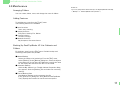
Guide to This Scanner
1
1
2
3
4
6
5
7
ZDLH0
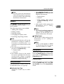
1. White Sheet
This holds documents against the Contact Glass.
2. ADF Contact Glass
Place the documents set at the Automatic
Document Feeder (ADF) to be scanned
here.
3. Contact Glass
Place the documents to be scanned here.
4. Lock Switch
Use to lock the internal scanning equipment when transporting the scanner.
5. Power Connector
Where the Power Cord is connected
6. IEEE1394 Connector (optional)
Where the IEEE1394 cable is connected
7. SCSI connector
Where the SCSI cable is connected
5
RuSCSup_EN-5_FM.book Page 6 Tuesday, October 9, 2001 5:04 PM
Getting Started
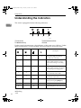
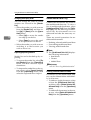
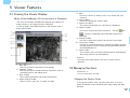
Understanding the Indicators
This unit is equipped with the following indicators.
1
1
2
3
4
ZDLH030E
1. Power On
2. Machine Busy
3. Document in Place
4. Error
Under normal circumstances, the indicators of this unit are as follows. Under
other circumstances, an error reading will occur. Refer to resolve the error.
Description
✩
✩
✩
✩
When switching on the power or
when performing a hard reset
(for only a few seconds)
6
✩
-
-
-
When the Automatic Document
Feeder (ADF) contains no documents and scanning is not taking
place
✩
-
✩
-
When the Automatic Document
Feeder (ADF) contains a document
but scanning is not taking place.
✩
✩
-
-
✩
✩
✩
-
✩
-
★
-
★
-
-
-
During the Low Power mode
★
-
★
-
When manual scan is in the standby
mode during the Low Power mode.
✩:On
★:Flashing
-:Off
During the transmission of scanned data
(No Documents in the ADF)
During the transmission of scanned data.
(Documents in the ADF)
During standby for manual scan.
(Before pressing the {Start} key)
RuSCSup_EN-5_FM.book Page 7 Tuesday, October 9, 2001 5:04 PM
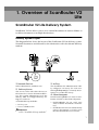
Confirmations Prior to Installation
Confirmations Prior to Installation
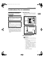
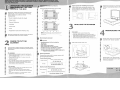
Confirming the Installation
Environment
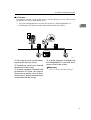
❖ Installation space
Install on a location that guarantees a space as shown in the illustration.
1
R WARNING:
• Confirm that the wall outlet is near the
machine and freely accessible, so that in
event of an emergency, it can be unplugged easily.
R CAUTION:
• Keep the machine away from humidity
and dust. A fire or an electric shock might
occur.
100mm or more
(3.9")
• Place the machine on a strong and level
surface. Otherwise, the machine might fall
and cause personal injury.
ZDLH040E
Select a horizontal, stable location
free from vibrations to install the unit.
• The Degree of levelness of the surface to install the unit on: left to
right and back to front, 5mm (0.2”)
or less.
660mm or more
(26.0")
ZDLH050E
❖ Installation environment
Important
❒ Do not install on the following
locations:
• On locations exposed to direct sun light
• On places exposed to direct
radiation or hot air from an
air-conditioner or heater
• Near electronic equipment
such as a radio, a TV, etc.
• Exceedingly hot, humid, cold
locations
• Near a humidifier
7
RuSCSup_EN-5_FM.book Page 8 Tuesday, October 9, 2001 5:04 PM
Getting Started
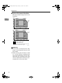
❖ Optimum Environmental Conditions
Recommended temperature and
humidity
%RH 10 C 80%
80
1
27 C 80%
15 C
70%
25 C
70%
40
15 C
30%
25 C
30%
20
10 C 15%
60
10
32 C 15%
20
%RH 50 F80%
80
80.6 F 80%
77 F
70%
40
59 F
30%
77 F
30%
20
50 F 15%
50
60
C
30
59 F
70%
60
32 C
54%
89.6 F
54%
89.6 F 15%
70
80
90
F
Possible operation range
Recommended range
The machine must be level within 5 mm, 0.2"
both front to rear and left to right.
TDLH140E
Important
❒ To be able to transport this unit,
keep its packaging material and
box handy.
❒ When moving the unit from a cold
to a warm location, condensation
can occur internally. In case condensation has occurred, allow the
unit to acclimatize to the new environment for at least one hour.
8
RuSCSup_EN-5_FM.book Page 9 Tuesday, October 9, 2001 5:04 PM
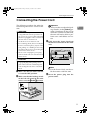
Connecting the Power Cord
Connecting the Power Cord
The following explains the order for
connecting the Power Cord to this
unit.
R WARNING:
• Do not use with a power source with a
voltage different from the specified voltage. Do not use a power outlet with multiple devices plugged in. These could create
the risk of fire or electric shock.
• Avoid the use of an extension cord.
• Do not damage, break, twist or modify the
Power Cord. Placing heavy objects on the
cord, pulling on or bending it excessively
can damage the Power Cord, creating the
risk of fire or electric shock.
Important
❒ Always make sure that the locking switch is in the {Unlock} position. Switching on the power
while this switch is not released,
the unit will not be able to perform scans and defects can occur.
1
C Fully insert the Power Cord into
the Power Connector on the main
unit.
• Never touch or unplug the power plug
with wet hands. This can create the risk of
electric shock.
R CAUTION:
• When unplugging from an outlet, be sure
to grasp the plug when pulling. Never
pull on the cord. This could damage the
cord creating the risk of fire or electrical
shock.
A Make sure that the Power Switch
is set to the OFF position.
B Make sure that the locking switch
ZDLH100E
Note
❒ For the Power Cord, use the cable that comes with this unit.
D Insert
the power plug into the
power outlet.
on the left side panel of the main
unit is set to the {Unlock}
} position.
ZDLH220E
9
RuSCSup_EN-5_FM.book Page 10 Tuesday, October 9, 2001 5:04 PM
Getting Started
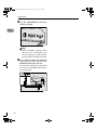
Connecting to the PC
This unit has an interface that complies with SCSI-2/3 standards and an
interface that complies with IEEE1394
standards (option). This explanation
describes the connection methods for
both types of interface.
1
Setting the SCSI ID
A Open the cover at the lower left of
the main unit.
Connecting to the SCSI
Interface
B Set the SCSI ID by rotating the
78
901
1
2
3
4
5
6
7
8
Rotary Switch.
456
10
ZDLS010E
23
Important
❒ When connecting this unit to other
SCSI devices through a daisychain,
possibly it doesn't work properly.
❒ The SCSI interface of this unit is of
the 50-pin half-pitch (pin-type)
type. Connect a shielded SCSI-2
compliant with ANSI standards or
a SCSI-3 (Ultra-SCSI) cable. When
other cables are used, there is the
possibility of malfunction or radio
interference due to exceeding the
maximum value of the FCC rules.
❒ It is possible that malfunction occurs or data is lost when more than
one SCSI ID's exists simultaneously. Adjust the settings such that the
SCSI ID of this unit does not coincide with the ID of another SCSI
device.
❒ Keep the total length of the SCSI
cable including the cable inside the
PC to a maximum of 1.5m (4.9 feet)
when using the SCSI-3 (Ultra-SCSI) and 3m (9.8 feet) when using
the SCSI-2.
❒ This unit may not work properly
in combination with other SCSI
boards or cables. If this is the case,
connect only this unit to the PC.
ZDLS030E
Note
❒ Press the Hard Reset Switch
w hen chang ing the sett in g
while the power is switched on.
RuSCSup_EN-5_FM.book Page 11 Tuesday, October 9, 2001 5:04 PM
Connecting to the PC
Connecting a SCSI cable
A Switch
off the power to the PC
and all devices connected
through the SCSI interface.
B Connect
the SCSI Connector of
this unit to the SCSI board of the
PC using the SCSI cable.
ZDLH110E
C Open the cover at the lower left of
the main unit and check the setting of the 3rd DIP switch.
• If this unit is the last unit of the
daisychain, set the 3rd DIP
switch to OFF.
• If this unit is not the last unit of
the daisychain, set the 3rd DIP
switch to ON.
Connecting to the IEEE1394
Interface (optional)
1
Important
❒ Use the cable that comes with the
IEEE1394 Board when using this
unit.
❒ When connecting multiple IEEE1394
compatible devices to multiple PC's,
the operation may become unstable.
Please make sure proper operation
when connecting multiple IEEE1394
compatible devices.
Reference
An IEEE1394 Interface can be used
by installing an optional IEEE1394
Board on this unit. For information
about how to install an IEEE1394
Board, refer to P.13 “Installing the
IEEE 1394 Board (IEEE 1394 Interface Board Type S)”.
A Open the cover at the lower left of
the main unit.
D Switch on the power to this unit
and the power of the PC.
For the installation of the necessary software when using this unit,
refer to P.17 “Installing the Scanner
drivers”.
ZDLS010E
11
RuSCSup_EN-5_FM.book Page 12 Tuesday, October 9, 2001 5:04 PM
Getting Started
B Set
the SCSI/IEEE1394 Selector
Switch to [1394].
1
78
23
901
456
ZDLS020E
Note
❒ When changing settings while
the power is switched on, be
sure to perform a hard reset by
pressing the Hard Reset Switch.
C Use a cable to connect the IEEE1394
connector of this unit to the
IEEE1394 connector of the PC.
Connect the side of the cable that
has a core to the IEEE1394 connector of this unit.
ZDLH120E
12
RuSCSup_EN-5_FM.book Page 13 Tuesday, October 9, 2001 5:04 PM
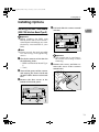
Installing Options
Installing Options
Installing the IEEE 1394 Board
(IEEE 1394 Interface Board Type S)
D Pull and slide the scanner control
1
unit out.
Important
❒ Before touching the IEEE 1394
Board, make sure to first touch a
metal object to discharge any static
electricity accumulated in your
body.
Note
❒ Please use only the tools provided
f or re m o vi ng an d t ig h te n ing
screws.
A Check the contents of the box for
the following items:
• IEEE 1394 Interface Board Type
S
• Tools
B Turn off the power of the scanner
ZDLH140E
Important
❒ The control unit is very heavy.
Be careful not to drop it when
removing.
E Remove the screw, and then re-
move the cover of the scanner
control unit.
and unplug the Power Cord and
all other cables that are connected
to it.
C Remove
the four screws at the
bottom of the back panel.
ZDLH150E
ZDLH130E
13
RuSCSup_EN-5_FM.book Page 14 Tuesday, October 9, 2001 5:04 PM
Getting Started
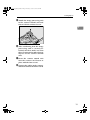
F Attach the IEEE 1394 Board to the
scanner control unit, and then fasten in place with the screws removed in step E and the screws
included w ith the IEEE 1394
Board.
1
A Check the contents of the box for
the following items:
• Image Processing Unit Type A
• Tools
B Turn off the power of the scanner
and unplug the Power Cord and
all other cables that are connected
to it.
C
Remove the four screws at the
bottom of the back panel.
ZDLH160E
G Be sure to attach firmly, and con-
firm that there are no metal objects or other foreign objects on
the scanner control unit.
H Insert
the scanner control unit
into the scanner, and then fasten
in place with the four screws.
I Connect the cables to the scanner,
ZDLH230E
D Pull and slide the scanner control
unit out.
and then connect the Power Cord.
Installation of Image Processing
Unit
(Image Processing Unit Type A)
Important
❒ Before touching the image processing unit, make sure to first touch a
metal object to discharge any static
electricity accumulated in your
body.
Note
❒ Please use only the tools provided
f or re m o vi ng an d t ig h te n ing
screws.
14
ZDLH230E
Important
❒ The control unit is very heavy.
Be careful not to drop it when
removing.
RuSCSup_EN-5_FM.book Page 15 Tuesday, October 9, 2001 5:04 PM
Installing Options
E Attach the image processing unit
to the scanner control unit and
fasten with the enclosed screw.
1
ZDLH170E
F After confirming that the image
processing unit is securely attached, check to make sure that
there are no metal or other foreign
objects on the scanner control
unit.
G Insert
the scanner control unit
into the scanner and fasten in
place with the four screws.
H Connect the cables to the scanner,
and then connect the Power Cord.
15
RuSCSup_EN-5_FM.book Page 16 Tuesday, October 9, 2001 5:04 PM
Getting Started
1
16
RuSCSup_EN-5_FM.book Page 17 Tuesday, October 9, 2001 5:04 PM
2. Installing the Scanner
drivers
This chapter assumes that the reader has sufficient understanding of the Windows operating system. Refer to the Windows operation manual for details
about its functions and operation.
The ways for installing the scanner driver on your computer vary depending on
your operating system. Follow the procedures described below (The following
is an explanation on how the TWAIN driver is installed. When installing the ISIS
Driver, refer to P.18 “Installing the Scanner Driver by Auto Run” and proceed with
the installation as mentioned there.).
Note
❒ The scanner driver in this manual is TWAIN or ISIS driver.
Using Windows98/ME, Windows2000
Install the Scanner driver after having installed the STI driver for Windows98/
Me or Windows2000 using the Plug & Play function of the OS. Here examples of
Windows98 are used for the explanations. The basic operations are similar for
Windows Me and Windows2000.
Installing the STI Driver
When connecting the scanner to a PC and the PC is started, the scanner can possibly be recognized as a different device. In order to allow the scanner to be recognized properly, it is necessary to install the STI driver stored on the supplied
CD-ROM. When using this product with Windows98/Me or Windows2000 be
sure to always install the STI driver.
Limitation
❒ To install the driver when using Windows2000, log-on as an Administrator
group member.
Note
❒ During the installation of the STI driver, the Windows98/Me or
Windows2000 CD-ROM may be required.
A Connect the scanner and start up the PC.
When starting up the PC for the first time after connecting the scanner, the
[Add New Hardware Wizard] appears.
17
RuSCSup_EN-5_FM.book Page 18 Tuesday, October 9, 2001 5:04 PM
Installing the Scanner drivers
Note
❒ If the [Add New Hardware Wizard] does not appear after starting up the PC,
click the [Device Manager] tab on [System] in the [Control Panel], select the
scanner name and click [Remove]. The [Confirm Device Removal] dialog box
will be displayed, click [OK] and restart the system. The scanner is now recognized as a [Unknown Device] and [Add New Hardware Wizard] appears.
B Click [Search for the best driver for your device. (recommended)] and click [Next].
C Select the [Specify a location] check box, input [ \DRIVERS\SC-
2
SI\STI\INF2000 ] after the CD-ROM drive name (in the case of
Windows98/Me) and input [ \DRIVERS\SCSI\STI\INF2000 ] after the
CD-ROM drive name (in the case of Windows2000).
For example, when the D drive is the CD-ROM drive, input [ C:\DRIVERS\SCSI\STI\INF98 ] or [ C:\DRIVERS\SCSI\STI\INF2000 ] respectively.
D Click [Next].
E Click [Next].
The [Insert disk] message appears.
F Place the CD-ROM included with this product into the CD-ROM drive and
click [OK].
G Click [Finish].
H Open [System] in the [Control Panel] and check that the scanner is correctly
identified by the [Device Manager].
Installing the Scanner Driver by Auto Run
You can install the scanner drivers and software, and set them up easily by using
Auto Run.
Follow these steps to install the scanner drivers and software on Windows 95/
98/Me, Windows 2000 or Windows NT 4.0.
Limitation
❒ If your system is Windows 2000 or Windows NT 4.0, installing a scanner driver by Auto Run requires Administrators permission. When you install a scanner driver by Auto Run, log on using an account that has Administrators
permission.
Note
❒ Auto Run might not automatically work with certain OS settings. In this case,
launch " CDLAUNCH.EXE " located on the CD-ROM root directory.
18
RuSCSup_EN-5_FM.book Page 19 Tuesday, October 9, 2001 5:04 PM
Using Windows98/ME, Windows2000
❒ If you want to cancel Auto Run, hold down the {SHIFT} key (when your system is Windows 2000, hold down the left {SHIFT} key) while inserting the CDROM. Keep the {SHIFT} key held down until the computer has finished accessing the CD-ROM.
A Close all applications that are running.
B Insert the CD-ROM into the CD-ROM drive.
C Follow the instructions on the screen.
D Restart the computer after installation is complete.
E Set up the options with the scanner driver.
2
19
RuSCSup_EN-5_FM.book Page 20 Tuesday, October 9, 2001 5:04 PM
Installing the Scanner drivers
Using Windows95, WindowsNT4.0
To install the scanner driver for Windows 95, WindowsNT4.0, refer to
P.18 “Installing the Scanner Driver by
Auto Run”.
2
Limitation
❒ To install the driver when using
WindowsNT4.0, log-on as a member of the Administrator group.
20
RuSCSup_EN-5_FM.book Page 21 Tuesday, October 9, 2001 5:04 PM
Using WindowsNT3.51
Using WindowsNT3.51
To install the scanner driver for
WindowsNT3.51, follow the steps described below.
Limitation
❒ To install the driver when using
W ind o w sNT3.51, lo g-o n as a
member of the Administrator
group.
❒ The ISIS Driver does not work
with Windows NT3.51.
2
Installing the TWAIN driver
A Place the CD-ROM included with
this product into the CD-ROM
drive.
B Select [Run] from the [File] menu
in the [File Manager].
The [Run] dialog box appears.
C Inside the [Command Line] box, input [
DRIVERS\SCSI\TWAIN\OTHERS\SETUP ] after the name of the
drive in which the CD-ROM is located and click [Finish].
For example, if the CD-ROM is
placed in the D drive, input [D:
\DRIVERS\SCSI\TWAIN\OTHERS\SETUP ]
D Follow
the instructions on the
screen.
E Restart the computer after installation is complete.
21
RuSCSup_EN-5_FM.book Page 22 Tuesday, October 9, 2001 5:04 PM
Installing the Scanner drivers
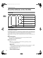
About the Software on the CD-ROM
List of Files
The CD-ROM includes the software below.
2
CDROM
DRIVE
DRIVERS
SCSI
TW
AIN
Japa- TWAIN driver for Windows95/98/Me,
Windows2000, WindowsNT3.51/4.0
nese
Others
TWAIN driver for Windows95/98/Me,
Windows2000, WindowsNT3.51/4.0
INF9 STI driver for Windows98/Me
STI
8
INF2 STI driver for Windows2000
000
ISIS
ISIS driver for Windows95/98/Me,
Windows2000, WindowsNT4.0
UTILITY
TWAIN Driver
TWAIN driver is the driver used to enable this unit to scan documents. Make
sure this driver is installed.
By selecting a device of a commercially available TWAIN compatible driver,
when designating this driver, it will automatically start up when scanning documents and it will scan according to designated scanning conditions.
If the multiple scanning mode is stored beforehand, it can be recalled when scanning.
❖ Files storing location
Files are stored in the following location in the provided CD-ROM.
\DRIVERS\SCSI\TWAIN\Others\
❖ Operating environment
• PC
The driver is compatible with the following operating systems:
PC/AT compatible machines
Limitation
❒ When used with WindowsNT, the driver will not operate in a RISCbased (MIPS R-series, Alpha AXP, Power PC) environment.
• Compatible Operating Systems
Microsoft Windows 95
Microsoft Windows 98, 98SE
Windows Millenium Edition
22
RuSCSup_EN-5_FM.book Page 23 Tuesday, October 9, 2001 5:04 PM
About the Software on the CD-ROM
Windows 2000 Professional
Windows 2000 Server
Windows NT WorkStation 4.0 Service Pack 5.0 or higher
Windows NT Server 4.0 Service Pack 5.0 or higher
Windows NT 3.51 Service Pack 5.0 or higher
• Display resolution
SVGA 800x600
• TWAIN compatible applications
Applications compatible with TWAIN version 1.6 or higher
2
ISIS Driver
The ISIS Driver is necessary for scanning documents with the scanner. It is possible to scan documents, when calling up the ISIS Driver with applications that
are compatible with ISIS. It is also possible to use the driver when connecting a
computer and the machine through a SCSI interface.
❖ Files storing location
Files are stored in the following location in the provided CD-ROM.
\DRIVERS\SCSI\ISIS\
❖ Operating environment
• PC
The driver is compatible with the following operating systems:
PC/AT compatible machines
Limitation
❒ When used with WindowsNT, the driver will not operate in a RISCbased (MIPS R-series, Alpha AXP, Power PC) environment.
• Compatible Operating Systems
Microsoft Windows 95
Microsoft Windows 98, 98SE
Windows Millenium Edition
Windows 2000 Professional
Windows 2000 Server
Windows NT WorkStation 4.0 Service Pack 5.0 or higher
Windows NT Server 4.0 Service Pack 5.0 or higher
Limitation
❒ The ISIS Driver does not work with Windows NT3.51.
• Display resolution
SVGA 800x600
23
RuSCSup_EN-5_FM.book Page 24 Tuesday, October 9, 2001 5:04 PM
INDEX
A
About the Software on the CD-ROM, 22
ADF Contact Glass, 5
Automatic Document Feeder (ADF), 4
Auto Run, 18
C
Caution, ii
Confirming the Installation Environment,
7
Connection
IEEE1394 Interface, 11
Power Cord, 9
SCSI Interface, 10
Contact Glass, 5
D
DIP Switches, 4
Document Tray, 4
G
Guide to This Scanner, 4
H
Hard Reset Switch, 4
I
IEEE1394 Connector (optional), 5
Indicators, 4
Installing Options, 13
Image Processing Unit, 14
IEEE1394 Board, 13
Installing the STI driver, 17
ISIS Driver, 23
L
Lock Switch, 5
O
Output Tray, 4
P
Power Connector, 5
24
Power Switch, 4
Q
Quick Installation Guide, v
R
{Reset} key, 4
Rotary Switch, 4
S
Scanner Reference, v
SCSI Connector, 5
SCSI/IEEE1394 Selection Switch, 4
Setup Guide, v
{Start}, 4
T
TWAIN Driver, 22
U
Understanding the indicators, 6
W
Warning, ii
White Sheet, 5
RuSCSup_EN-5_FM.book Page 1 Tuesday, October 9, 2001 5:04 PM
Color Scanner Setup Guide
Printed in the Japan
UE USA G412-6653
RuSCSup_EN-5_FM.book Page 1 Tuesday, October 9, 2001 5:04 PM
Color Scanner Setup Guide
Printed in the Japan
UE USA G412-6653
Color Scanner
Operating Instructions
Scanner Reference
ZDLH001E.eps
Read this manual carefully before you use this product and keep it handy for future
reference.
For safety, please follow the instructions in this manual.
Introduction
This manual contains detailed instructions on the operation and maintenance of this machine. To get
maximum versatility from this machine all operators should carefully read and follow the instructions in
this manual. Please keep this manual in a handy place near the machine.
Please read the Safety Information before using this machine. It contains important information related
to USER SAFETY and PREVENTING EQUIPMENT PROBLEMS.
Power Source
Color Scanner: 120 V, 60 Hz, 10A or more
Please be sure to connect the Power Cord to a power source as above.
Two kinds of size notation are employed in this manual. With this machine refer to the inch version.
Important
Parts of this manual are subject to change without prior notice. In no event will the company be liable
for direct, indirect, special, incidental, or consequential damages as a result of handling or operating
the machine.
Caution:
Use of controls or adjustment or performance of procedures other than those specified in this manual
might result in hazardous radiation exposure.
Do not attempt any maintenance or troubleshooting other than that mentioned in this manual. This
scanner contains a laser beam generator and direct exposure to laser beams can cause permanent
eye damage.
Two kinds of size notation are employed in this manual. With this machine refer to the inch version.
Ricoh shall not be responsible for any damage or expense that might result from the use of parts other
than genuine Ricoh parts in your Ricoh office product.
Trademarks
Microsoft®, Windows® and Windows NT ® are registered trademarks of Microsoft Corporation in the United States and/or other countries.
Other product names used herein are for identification purposes only and might
be trademarks of their respective companies. We disclaim any and all rights in
those marks.
Notes:
Some illustrations might be slightly different from your machine.
Certain options might not be available in some countries. For details, please contact your local dealer.
Note
The proper names of the Windows operating systems are as follows:
• Microsoft® Windows® 95 operating system
• Microsoft® Windows® 98 operating system
• Microsoft® Windows® Millennium Edition (Windows Me) operating system
• Microsoft® Windows® 2000 Professional
• Microsoft® Windows® 2000 Server
• Microsoft® Windows NT® Server operating system Version 4.0
• Microsoft® Windows NT® Workstation operating system Version 4.0
• Microsoft® Windows NT® Server network operating system version 3.51
• Microsoft® Windows NT® Workstation operating system version 3.51
i
Safety Information
When using your scanner, the following safety precautions should always be
followed.
Safety During Operation
In this manual, the following important symbols are used:
R WARNING:
Indicates a potentially hazardous situation which, if instructions
are not followed, could result in death or serious injury.
R CAUTION:
Indicates a potentially hazardous situation which, if instructions are
not followed, may result in minor or moderate injury or damage to
property.
R WARNING:
• Connect the Power Cord directly into a wall outlet and never use an extension cord.
• Disconnect the power plug (by pulling the plug, not the cable) if the power cable or plug
becomes frayed or otherwise damaged.
• To avoid hazardous electric shock or laser radiation exposure, do not remove any covers
or screws other than those specified in this manual.
• Turn off the power and disconnect the power plug (by pulling the plug, not the cable) if
any of the following conditions exists:
• You spill something into the equipment.
• You suspect that your equipment needs service or repair.
• Your equipment's cover has been damaged.
• Disposal can take place at our authorized dealer or at appropriate collection sites.
ii
R CAUTION:
• Protect the equipment from dampness or wet weather, such as rain, snow, and so on.
• Unplug the Power Cord from the wall outlet before you move the equipment.
While moving the equipment, you should take care that the Power Cord will not be damaged under the equipment.
• When you disconnect the power plug from the wall outlet, always pull the plug (not the
cable).
• Do not allow paper clips, staples, or other small metallic objects to fall inside the equipment.
• For environmental reasons, do not dispose of the equipment or expended supply waste
at household waste collection points. Disposal can take place at an authorized dealer or
at appropriate collection sites.
• The inside of the machine could be very hot. Do not touch the parts with a label indicating
the "hot surface". Otherwise it could cause a personal burn.
• Our products are engineered to meet high standards of quality and functionality, and we
recommend that you only use the expendable supplies available at an authorized dealer.
Lithium Batteries (Memory Back-up)
R WARNING:
• Do not try to replace the lithium batteries by yourself. A battery of this type can explode
if incorrectly replaced. If the lithium batteries need to be replaced, contact an authorized
dealer to request servicing.
• Never dispose of the lithium batteries by incineration. This can cause them to rupture resulting in injury.
Note
❒ Please return used NIC boards to our authorized dealer or service representative.
Your cooperation with our recycling activities is appreciated.
❒ NIC boards are equipped with a lithium battery. In the case NIC boards are disposed
of by the customer, please dispose them in accordance with national or local regulations after separating the lithium batteries from the NIC board.
iii
Energy Star Program
As an ENERGY STAR Partner, we have determined
that this machine model meets the ENERGY STAR
Guidelines for energy efficiency.
The ENERGY STAR Guidelines intend to establish an international energy-saving system for
developing and introducing energy-efficient office equipment to deal with environmental issues, such as global warming.
When a product meets the ENERGY STAR Guidelines for energy efficiency, the Partner shall
place the ENERGY STAR logo onto the machine model.
This product was designed to reduce the environmental impact associated with office equipment by means of energy-saving features, such as Low-power mode.
❖ Energy Saver mode
This unit automatically lowers its power consumption at a predetermined
time (approximately 15 minutes) after the last operation was performed. To
operate the unit from this mode, see the instructions below.
• Method for clearing
• Put a document on the Document Tray.
• Open the cover of the Automatic Document Feeder (ADF).
• Open the White Sheet cover.
• Follow the instructions from the PC.
Note
❒ The Energy Saver mode does not work in the following conditions.
• When an optional device is attached.
• When an error occurs.
• When a document is placed on the Document Tray.
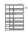
❖ Specifications
Energy Saver mode
iv
Power Consumption
Approx. 11W
Default Time
15 minutes
Manuals for This Scanner
Manuals for This Scanner
The following manuals describe the operational and maintenance procedures of
this machine.
To enhance safe and efficient operation of this scanner, all users should read and
follow the instructions carefully.
❖ Quick Installation Guide
Describes how to install the scanner.
❖ Setup Guide
Provides information about setting up the scanner and its options. This manual is provided as a printed manual, and also as a PDF file on the CD-ROM.
❖ Scanner Reference(this manual)
Provides information about using the scanner. This manual is provided as a
PDF file.
❖ Network Interface Kit Installation Guide
Describes how to install the Network Interface Kit (Network Interface Board
Type S and Operation Unit).
Note
❒ There is a CD-ROM that comes with this scanner.
v
How to Read This Manual
Symbols
In this manual, the following symbols are used:
R WARNING:
This symbol indicates a potentially hazardous situation which, if instructions
are not followed, could result in death or serious injury.
R CAUTION:
This symbol indicates a potentially hazardous situation which, if instructions
are not followed, may result in minor or moderate injury or damage to property.
* The statements above are notes for your safety.
Important
If this instruction is not followed, paper might be misfed, originals might be
damaged, or data might be lost. Be sure to read this.
Preparation
This symbol indicates the prior knowledge or preparations required before operating.
Note
This symbol indicates precautions for operation, or actions to take after misoperation.
Limitation
This symbol indicates numerical limits, functions that cannot be used together,
or conditions in which a particular function cannot be used.
Reference
This symbol indicates a reference.
[
]
Keys that appear on the machine's panel display.
Keys and buttons that appear on the computer's display.
{
}
Keys built into the machine's operation panel.
Keys on the computer's keyboard.
vi
TABLE OF CONTENTS
1. Setting the Document
Size of Documents that can be Set..........................................................
Document Sizes that can be Scanned Automatically....................................
Documents that Require Special Care ..........................................................
Placing the Document on the Contact Glass..........................................
Setting Documents in the Automatic Document Feeder (ADF) ............
Simples Scanning .........................................................................................
Duplex Scanning ...........................................................................................
1
1
4
5
6
7
8
2. Scanning Documents
General Scanning Method ........................................................................ 9
Manual Scanning..................................................................................... 10
The Relationship between the Data Size and the Scanning Area, as well
as the Resolution................................................................................... 11
When in [Binary] [half-tone] is Selected ...................................................... 11
When [gray-scale] is Selected..................................................................... 12
When [8 Colors] [8 Colors (half-tone) is Selected ....................................... 13
When [256 colors] is Selected..................................................................... 14
When [16,770,000 colors] is selected ......................................................... 15
3. Troubleshooting
When Scanning does not Start .............................................................. 17
When Scanning is not Performed as Expected. ................................... 18
When the Indicators Show an Error Reading ....................................... 19
When a Document is Jammed inside the Automatic Document Feeder
(ADF)....................................................................................................... 20
Cleaning ................................................................................................... 21
Cleaning the Contact Glass, ADF Contact Glass, White Sheet, and White
Plate ......................................................................................................... 21
Cleaning the Feed Roller ............................................................................ 22
Cleaning the Document Roller ................................................................... 22
Cleaning the Document Rolling Unit ........................................................... 23
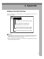
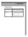
4. Appendix
Setting of the DIP Switches ....................................................................
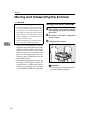
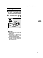
Moving and Transporting the Scanner..................................................
Moving Over Short Distances .....................................................................
Transporting the Scanner............................................................................
25
26
26
27
vii
Discarding the Unit..................................................................................
Precautions Concerning the IEEE1394 Interface .................................
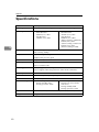
Specifications ..........................................................................................
Options .....................................................................................................
28
29
30
31
INDEX........................................................................................................ 32
viii
1. Setting the Document
This chapter describes the methods used for setting documents on this unit for
scanning.
The document can be set on the Contact Glass or the Automatic Document Feeder (ADF). For scanning multiple documents in a row, the Automatic Document
Feeder (ADF) is convenient.
Size of Documents that can be Set
Position for
setting document
Size of document
Document weight
Contact Glass
Maximum A3 , 11×17 (DLT)
No restrictions
Automatic
Document
Feeder (ADF)
❖ Standard size
41(1.4oz)∼128g(4.5oz)/m2
Max. A3L, 11”×17”L
Min. A5L, 8.5”×5.5”(HLT)L
(35∼110Kg(77.2∼242.5lb))
❖ Non-standard size
Max:297mm(11.7”)×2000mm(78.8
”)(when scanning in binary),
297mm(11.7”) × 630mm(24.9”)
(when scanning in color)
Min: 105mm(4.1”) × 128mm(5.0”)
Document Sizes that can be Scanned Automatically
The sizes of documents that this unit can automatically detect and scan are as
follows.
Feed direction
Size (mm)
❖ Contact Glass (Metric version)
A3
K
297 × 420
B4
K
257 × 364
A4
K
210 × 297
L
297 × 210
K
182 × 257
L
257 × 182
B5
1
Feed direction
Size (mm)
Setting the Document
Foolscap
(F4, 8.5" × 13")
K
216 × 330
F/GL (8" × 13")
K
203 × 330
1
Note
❒ F/GL size is detected same as the F4 size.
Feed direction
Size (inch)
❖ Contact Glass (Inch version)
Double Letter
(DLT)
K
11" × 17"
11”× 15”
K
11" × 15"
Note
❒ This size is detected same as DLT size.
10”× 14”
K
10" × 14"
Legal (LG)
K
8.5"× 14"
Letter (LT)
K
8.5" × 11"
L
11" × 8.5"
K
8" × 10"
8”× 10”
Feed direction
Size (mm)
❖ Automatic Document Feeder (ADF)(Metric version)
A3
K
297 × 420
B4
K
257 × 364
A4
K
210 × 297
L
297 × 210
K
182 × 257
L
257 × 182
B5
2
Foolscap (F4, 8.5" ×
13")
Size (mm)
A5
Feed direction
Size of Documents that can be Set
K
148 × 210
L
210 × 148
K
216 × 330
1
Note
❒ Foolscap size is detected same as the F/GL
size.
F/GL (8" × 13")
K
203 × 330
Feed direction
Size (inch)
❖ Automatic Document Feeder (ADF)(Inch version)
Double Letter (DLT)
K
11" × 17"
11”× 15”
K
11" × 15"
Note
❒ This size is detected same as the DLT size.
10”× 14”
K
10" × 14"
Legal (LG)
K
8.5"× 14"
F/GL
K
8"× 13"
Note
❒ This size is detected same as the LG size.
Letter (LT)
8”× 10”
K
8.5" × 11"
L
11" × 8.5"
K
8" × 10"
Note
❒ This size is detected same as the LT size.
Half Letter(HLT)
K
5.5" × 8.5"
L
8.5" × 5.5"
3
Setting the Document
Documents that Require Special Care
Make sure to take care in setting the document according to the following instructions when scanning the following types of documents.
1
❖ Documents whose size is difficult to scan
As the following documents are difficult to scan their size, the correct size will
not be selected, even if the automatic size detection has been set. The sizes for
these documents should be manually set.
• Documents with projecting parts such as indices or attached lines
• Document with a high degree of transparency such as tracing paper or
OHP film
• Documents which are fully dark in color or which have a high content of
character or graphic patterns
• Documents with partially adhesive areas
• Documents with surrounding adhesive areas
❖ Documents that cannot be set into the Automatic Document Feeder (ADF)
The following types of documents should not be set into the Automatic Document Feeder (ADF) as these can cause paper jams, damage to the original
document, or black and white lines. If these types of documents are to be
used, use the Contact Glass of the scanner.
• Documents with staples or paper clips
• Documents with holes and rips
• Documents with bends, folds or wrinkles
• Pasted documents
• Thermal paper, art paper, aluminum foil, carbon paper, or processed paper with conductive paper on the back
• Perforated paper
• Documents with projecting parts such as indices or attached lines
• Documents that do not slide easily such as tracing paper (translucent paper)
• Documents that are thin and soft, such as registration paper
• Documents that have an unsuitable thickness such as postcards
• Documents that are bound such as books
• Documents that have a high transparency rate such as OHP film or tracing
paper
• Documents with not completely dried ink or correction liquid
4
Placing the Document on the Contact Glass
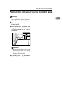
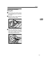
Placing the Document on the Contact Glass
Important
❒ Take care that your fingers do not
get caught when closing the Automatic Document Feeder (ADF).
1
A Open
the Automatic Document
Feeder (ADF).
B Place documents face down and
PS
aligned with the scale.Documents
should conform to the setting
standards.
ZDLH180E
Important
❒ Do not forcefully press down on
the Contact Glass. If a strong
force is applied to a small area,
the glass may be break.
C Carefully
close the Automatic
Document Feeder (ADF).
5
Setting the Document
Setting Documents in the Automatic
Document Feeder (ADF)
1
Multiple documents can be set in the
automatic document feeder(ADF). In
this manual, documents that can be
set in the Automatic Document Feeder (ADF) are called "sheet documents". Not only can documents set
in the Automatic Document Feeder
(ADF) be scanned on one side, they
can be scanned on both sides.
6
❖ Documents that cannot be set in the
Automatic Document Feeder (ADF)
• Documents that do not match
the size and paper weight of
documents that can be set
• Documents with staples, clips,
glue, etc.
• Documents with holes and rips
• Documents with bends, folds,
and wrinkles
• Pasted documents
• Wet documents
• Documents not made of paper
• Documents with coating (CFF,
etc.)
• Photos, documents that are
prints or printed photos
• Thermal fax paper, art paper,
aluminum foil, carbon paper,
processed paper with conductive paper on the back
• Documents with projecting parts
such as indices or attached lines
• Documents that do not slide
easily such as tracing paper
(translucent paper)
• Documents that are thin and
soft, such as registration paper
• Documents that have an unsuitable thickness such as postal
cards
• Documents that are bound, such
as books
• Documents that are transparent
such as OHP film,or tracing paper
• Documents that have curls such
as shown in the illustration below
5mm(0.2") or more
10mm(0.4") or more
Important
❒ Setting documents that should
not be set in the Automatic Document Feeder (ADF) can cause
jams and break downs. Place
these documents on the Contact
Glass.
❖ Advice when Setting documents in
the Automatic Document Feeder
(ADF)
• Do not set more documents
than indicated.
• For document sizes that can be
automatically detected, refer to
P.1 “Document Sizes that can be
Scanned Automatically”.
Setting Documents in the Automatic Document Feeder (ADF)
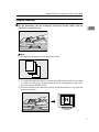
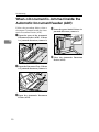
Simples Scanning
A Set the documents into the Automatic Document Feeder (ADF) with the
1
side to be scanned face up.
ZDLY010E
Note
❒ Arrange the documents in the preferred order.
1
2
3
TACY050E
❒ To avoid multiple sheet feeds (in which the ADF feeds more than one sheet
at a time), fan the pages of the document before setting them in the Automatic Document Feeder (ADF).
❒ Set the document in the direction shown in the illustration to scan with the
proper orientation.
ZDLY020E
7
Setting the Document
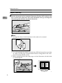
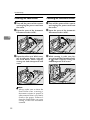
Duplex Scanning
A Set the documents in the Automatic Document Feeder (ADF) with the side
1
to be scanned first (the front side of the document) face up, and align the
document guide with the size of the documents.
ZDLY010E
Note
❒ Arrange the sheets of the documents in the order to be scanned.
2
1
3
4
5
6
TACY060E
❒ To avoid multiple sheet feeds (in which the ADF feeds more than one sheet
at a time), fan the pages of the document before setting them in the Automatic Document Feeder (ADF).
❒ When setting the front side of the page as in the illustration, the back side
is scanned upside.
ZDLY
8
2. Scanning Documents
General Scanning Method
Scanning of a document is initiated by the software that is TWAIN or ISIS compatible. The method of operation depends on the software. For details, refer to
the manual that was supplied with your software.
Limitation
❒ When using duplex scanning, if the leading edge of the reverse side of the
document is dark, the scanned image may appear whitish.
❒ When using the ISIS Driver, the image resolution will be limited. If the scanning image is smaller than the size set with the ISIS Driver, lower the resolution (at maximum 675 dpi) using the resolution settings and the area.
9
Scanning Documents
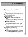
Manual Scanning
By setting up a scanner driver that supports the manual scanning function, scanning can be initiated by pressing the {Start} key.
If the manual scanning function is used, then communications between the scanner and the personal computer are no longer needed in cases where it is necessary to set the document in the scanner one sheet at a time, for example.
2
A Set the manual scanning function through the scanner driver.
B Set the documents in the scanner.
C Press the {Start}} key. To end manual scanning, press the {Reset}} key.
10
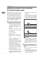
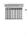
The Relationship between the Data Size and the Scanning Area, as well as the Resolution
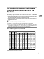
The Relationship between the Data Size
and the Scanning Area, as well as the
Resolution
The resolution and the scanning area as well as the data size are all affected in
the following way.
• When the resolution (dpi) is set to a high value, the data size becomes larger
and the scanning area which can be set becomes smaller.
• When the scanning area is set larger, the data size becomes larger, and the resolution becomes lower.
2
Note
❒ The size of the scanning area is the standard.
❒ Scanning is not possible when there are blank fields in the setting.
❒ A data size that works with applications and a data size that can scan with a
scanner driver are different. For a data size that can work with applications,
refer to the manuals that came with each of the applications.
When in [Binary] [half-tone] is Selected
Paper Width Height
size (mm / inch) (mm / inch)
Resolution(dpi)
100
200
400
600
1200
2000
2400
A3
297/11.7 420/16.5
236
943
3772
8487
33968
94398 135942
A4
210/8.3 297/11.7
118
470
1886
4247
16991
47181
67969
A5
148/5.8
210/8.3
58
234
940
2117
8468
23511
33870
A6
105/4.1
148/5.8
29
117
469
1058
4233
11755
16935
B4
257/10.1 364/14.3
176
705
2827
6365
25475
70785 101948
B5
182/7.2 257/10.1
88
354
1415
3183
12734
35393
50972
B6
128/5.0
182/7.2
43
175
703
1583
6339
17619
25386
279/11.0 432/17.0
227
910
3647
8201
32826
91216 131353
LG
216/8.5 356/14.0
145
580
2327
5231
20940
58170
83800
LT
216/8.5 279/11.0
114
455
1823
4099
16412
45588
65676
216/8.5
56
227
913
2058
8231
22870
32955
297/11.7 2000/78.7
1123
4491
17963
11× 17
5.5 × 8.5
Long
140/5.5
40416 161755
Numerical Value: Data Size (Unit = KB)
11
Scanning Documents
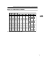
When [gray-scale] is Selected
Paper Width Height
size (mm / inch) (mm / inch)
2
Resolution(dpi)
100
200
400
600
A3
297/11.7 420/16.5
1887
7551
30209
67965
A4
210/8.3 297/11.7
943
3774
15104
33979 135939
A5
148/5.8
210/8.3
469
1881
7525
16934
A6
105/4.1
148/5.8
235
940
3761
8467
B4
257/10.1 364/14.3
1415
5662
22654
50967 203883
B5
182/7.2 257/10.1
707
2831
11327
25483 101942
B6
128/5.0
182/7.2
352
1409
5640
12691
11 × 17 279/11.0 432/17.0
1823
7294
29185
65668
LG
216/8.5 356/14.0
1163
4653
18619
41897 167589
LT
216/8.5 279/11.0
911
3646
14590
32834 131347
140/5.5
216/8.5
457
1829
7320
16477
297/11.7 432/17.0
1941
7765
31072
69903
5.5 × 8.5
Long
Numerical Value: Data Size (Unit = KB)
12
1200
2000
2400
67742 188166
33868
94077 135484
50774 141033 203094
65907 183074
The Relationship between the Data Size and the Scanning Area, as well as the Resolution
When [8 Colors] [8 Colors (half-tone) is Selected
Paper Width Height
size (mm / inch) (mm / inch)
Resolution(dpi)
100
200
400
600
1200
33977 135929
2000
2400
2
A3
297/11.7 420/16.5
943
3775
15101
A4
210/8.3 297/11.7
471
1886
7550
16989
A5
148/5.8
210/8.3
235
939
3762
8467
33871
94075 135484
A6
105/4.1
148/5.8
117
470
1879
4233
16934
47033
B4
257/10.1 364/14.3
707
2830
11324
B5
182/7.2 257/10.1
353
1415
5663
12739
B6
128/5.0
182/7.2
176
704
2818
6344
279/11.0 432/17.0
911
3647
14589
LG
216/8.5 356/14.0
581
2327
9307
20949
83794
LT
216/8.5 279/11.0
456
1823
7293
16417
65673 182416
140/5.5
216/8.5
228
915
3660
8236
297/11.7 432/17.0
970
3883
15533
11× 17
5.5 × 8.5
Long
67963 188793
67735
25483 101933
50971 141593 203892
25383
70516 101547
32834 131343
32954
91529 131821
34947 139814
Numerical Value: Data Size (Unit = KB)
13
Scanning Documents
When [256 colors] is Selected
Paper Width Height
size (mm / inch) (mm / inch)
2
Resolution(dpi)
100
200
400
600
A3
297/11.7 420/16.5
1887
7551
30209
67965
A4
210/8.3 297/11.7
943
3774
15104
33979
A5
148/5.8
210/8.3
469
1881
7525
16934
67742
A6
105/4.1
148/5.8
235
940
3761
8467
33868
B4
257/10.1 364/14.3
1415
5662
22654
50967
B5
182/7.2 257/10.1
707
2831
11327
25483
B6
128/5.0
182/7.2
352
1409
5640
12691
11× 17 279/11.0 432/17.0
1823
7294
29185
65668
LG
216/8.5 356/14.0
1163
4653
18619
41897
LT
216/8.5 279/11.0
911
3646
14590
32834
140/5.5
216/8.5
457
1829
7320
16477
297/11.7 432/17.0
1941
7765
31072
69903
5.5 × 8.5
Long
Numerical Value: Data Size (Unit = KB)
14
1200
50774
65907
2000
2400
The Relationship between the Data Size and the Scanning Area, as well as the Resolution
When [16,770,000 colors] is selected
Paper Width Height
size (mm / inch) (mm / inch)
Resolution(dpi)
100
200
400
600
1200
A3
297/11.7 420/16.5
5661
22652
90626 203894
A4
210/8.3 297/11.7
2829
11322
45313 101937
A5
148/5.8
210/8.3
1408
5642
22574
50801 203225
A6
105/4.1
148/5.8
704
2819
11284
25401 101603
B4
257/10.1 364/14.3
4244
16986
B5
182/7.2 257/10.1
2121
8493
33981
76450
B6
128/5.0
182/7.2
1055
4228
16919
38074 152321
11× 17 279/11.0 432/17.0
5469
21881
87555 197005
216/8.5 356/14.0
3489
13960
55857 125692
LT
216/8.5 279/11.0
2734
10937
43771
98502
140/5.5
216/8.5
1372
5488
21960
49431 197722
297/11.7 432/17.0
5822
23296
Long
2400
2
67961 152900
LG
5.5 × 8.5
2000
93216 209710
Numerical Value: Data Size (Unit = KB)
15
Scanning Documents
2
16
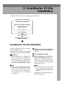
3. Troubleshooting
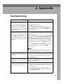
This section explains the possible causes and actions to take when the scanner
does not scan an image in the expected manner or when the indicators of this
unit show an error reading.
When Scanning does not Start
The interface cable is not correctly
connected
• Use a suitable interface cable.
The locking switch is in the locked
position.
• When scanning does not start and a strange noise can
be heard when switching on the power, the locking
switch at the left side of the main unit is in the locked
position. Turn the switch to {Unlock}.
The power can not be switched on
• First make sure the power plug is inserted into a
household outlet; then set the Power Switch to ON.
No document is set
• Set a document on the Contact Glass or in the Automatic Document Feeder (ADF).
The unit is not recognized as an
SCSI device
• First switch on the power of the scanner, then the
power of the PC.
• Make sure that the interface cable is properly connected.
• When changing the SCSI ID while the power is on,
press the Hard Reset Switch.
• Make sure the SCSI ID is correctly set.
• Make sure the cable is properly connected.
17
Troubleshooting
When Scanning is not Performed as Expected.
The scanned image is dirty
• The Contact Glass, the ADF Contact Glass, the White
Sheet or the Document Roller is dirty. ⇒ P.21 “Cleaning”
• Clean the Contact Glass, the ADF Contact Glass, the
White Sheet and the Document Roller. ⇒ P.21 “Cleaning”
The scanned image is distorted or
out of position
• The document was moved while being scanned. Do
not move the document during scanning.
• The document is not pressed flat against the Contact
Glass. Make sure the document is pressed flat against
the Contact Glass.
3
• Be sure to tightly align the guide of the Automatic
Document Feeder (ADF) with the size of the document.
The scanned image is upside down • The document was placed upside down. Set the document in the correct direction.
The document image cannot be
scanned
• The document was placed with the front and back reversed. Set the document in the correct direction.
• When setting documents on the Contact Glass, place
the side to be scanned face down; when setting documents in the Automatic Document Feeder (ADF), set
the side to be scanned face up.
• Make sure the locking switch is in the unlocked position.
18
The horizontal and vertical ratios of
the image do not coincide
• Assign the same values to X and Y using the resolution settings.
The scanning image is smaller that
the size set by the ISIS Driver
• Values which go over the limits of the hardware, have
been set in the area and resolution settings. Re-set the
resolution by assigning lower values.
Dirt sticks to the document
• Clean the Feed Roller, Document Roller and Document Rolling Unit. ⇒ P.21 “Cleaning”
When the Indicators Show an Error Reading
When the Indicators Show an Error Reading
This section explains the meaning of error readings displayed on the indicator
of this unit and the measures to be taken.
Note
❒ If an error that is not shown in the previous table occurs, switch off the unit
and then switch the power back on. If the error reading has not disappeared,
contact your nearest service shop and give a description of the error reading.
Error description
Solution
Close the Automatic Document Feeder (ADF) or
its cover fully.
✩
-
-
✩
The Automatic Document Feeder (ADF) or its
cover is not fully closed.
✩
-
★
✩
A document is jammed
Remove the jammed docinside the Automatic
ument.
Document Feeder (ADF).
✩
-
✩
✩
The document is not trans- Remove the document
ported by the Automatic
that was not transported
Document Feeder (ADF) in correctly.
the expected way.
★
★
★
★
System error
3
Contact your nearest service shop.
✩:On
★:Blinking
-:Off
19
Troubleshooting
When a Document is Jammed inside the
Automatic Document Feeder (ADF)
Follow the procedure below when a
document is jammed inside the Automatic Document Feeder (ADF).
D Lower the green knob. If there is a
jammed document, remove it.
A Open the cover of the Automatic
Document Feeder (ADF). If there
is a jammed document, remove it.
3
ZDLH250E
E Close
the Automatic Document
Feeder (ADF).
ZDLH230E
B Open the Document Tray. If there
is a jammed document, remove it.
ZDLH240E
C Open
the Automatic Document
Feeder (ADF).
20
Cleaning
Cleaning
R WARNING:
• Never remove any covers or screws other
than those specified in this manual. The
inside of the scanner contains high-voltage components that can cause electrical
shock. Have all inspections, adjustments,
and repairs inside the scanner performed
by an authorized dealer only.
• Do not attempt to modify this scanner in
any way. Modification can cause fire or
electrical shock.
R CAUTION:
• When disconnecting the power cord, always make sure to hold onto the plug. Do
not pull on the power cord itself. This can
cause damage to the cord, fire or electrical
shock.
We recommend periodically cleaning
the scanner to ensure that it is in optimum operating condition. First, wipe
off the scanner with a dry, soft cloth.
Next, dampen a soft cloth with water,
wring it out tightly, and then wipe off
the scanner. Use a neutral detergent
for exterior portions of the scanner
where soiling cannot be removed
with water alone. Wipe off the rubber
rollers with ethyl alcohol, and then
wipe with a cloth dampened with water. Finally, wipe off the rollers and
exterior with a dry cloth to remove
any excess moisture.
Important
❒ Do not use volatile chemicals such
as benzene, paint thinner or spray
with insecticides. This can cause
deformation, discoloration and
cracking.
Cleaning the Contact Glass,
ADF Contact Glass, White
Sheet, and White Plate
R CAUTION:
• Be careful not to pinch your fingers when
closing the Automatic Document Feeder
(ADF).
3
A Turn off the power of the scanner
and unplug the power cord from
the outlet.
B Wipe off the scanner with a dry,
soft cloth.
1
2
3
4
ZDLH060E
1. White Plate
2. White Sheet
3. ADF Contact Glass
4. Contact Glass
❒ Wipe off the Automatic Document
Feeder (ADF) with a dry, clean
cloth when there is dust or soiling
present inside.
21
Troubleshooting
Cleaning the Feed Roller
Cleaning the Document Roller
A Turn off the power of the scanner
A Turn off the power of the scanner
B Open the cover of the Automatic
B Open the cover of the Automatic
and unplug the power cord from
the outlet.
Document Feeder (ADF).
and unplug the power cord from
the outlet.
Document Feeder (ADF).
3
ZDLH070E
C Open the roller unit. While turn-
ing it with your fingers, wipe off
the Feed Roller with a tightly
wrung out cloth dampened with
water .
ZDLH070E
C While
turning it with your fingers, wipe off the Document Roller (A
A ) with a tightly wrung out
cloth dampened with water.
ZDLH190E
ZDLH080E
Note
❒ Always make sure to clean the
Feed Roller after scanning a
document written in pencil or
other material that is not firmly
fixed to the paper. Failure to
clean the Feed Roller can cause
soiling of the next document
scanned.
22
Cleaning
Cleaning the Document
Rolling Unit
A Turn off the power of the scanner
and unplug the power cord from
the outlet.
B Open the cover of the Automatic
Document Feeder (ADF).
3
ZDLH070E
C Open
the Document Tray and
wipe off the Document Rolling
Unit with a tightly wrung out
cloth dampened with water.
ZDLH090E
23
Troubleshooting
3
24
4. Appendix
Setting of the DIP Switches
Only the settings for 2 or 3 DIP Switches can be changed for this unit. Do not
make other changes.
Leave in the OFF position and do not change.
OFF: SCSI built-in terminator ON
ON: SCSI built-in terminator OFF
OFF: SCSI simultaneous transmission enabled
ON: SCSI simultaneous transmission disabled
Leave in the OFF position and do not change.
ZDLS040E
Important
❒ Depending on the SCSI cable used, there is a possibility of malfunction during simultaneous transmission. In this case, set the 2nd DIP switch to ON
(SCSI :simultaneous transmission disabled).
❒ When switching off the SCSI built-in terminator, set the 3rd DIP switch to ON
(SCSI built-in terminator OFF).
25
Appendix
Moving and Transporting the Scanner
R CAUTION:
• This scanner weighs approximately 28 kg.
• When lifting, please make sure to lift slowly so as to minimize physical strain with
two persons or more while holding onto
the handles located in the center on both
sides. Failure to lift using proper caution,
reckless handling or allowing the scanner
to drop can cause injury.
• When transporting over long distances,
please consult an authorized dealer.
4
• Safety laws and regulations (including those stipulating radio wave regulations and material regulations)
differ in each country. Use of this
product and its consumable supplies, etc. in foreign countries in violation of these regulations may be
punishable by law.
• Information regarding measures for
ensuring safe transport can be obtained from an authorized dealer.
However, packaging and transport
are to be performed by the customer.
26
Moving Over Short Distances
A Turn off the power of the scanner
and unplug the power cord from
the outlet.
B Disconnect
all cables connected
to the scanner.
C Transport the scanner.
ZDLH200E
Important
❒ Try to keep the scanner as level as
possible during transport.
Moving and Transporting the Scanner
Transporting the Scanner
A Turn on the Power Switch. Allow
the scanner to remain on for at
least 20 seconds, and then turn it
off.
B Set
the Lock Switch on the left
side of the scanner to the {Lock}
}
position.
4
ZDLH210E
C Place the scanner in the original
box and transport.
Important
❒ Disconnect all cables connected
to the scanner.
❒ This scanner is a precision device. Be careful so that it is not
damaged during transport.
❒ Use the cushioning materials
provided with the scanner at
the time of purchase.
27
Appendix
Discarding the Unit
When you want to discard the unit,
consult the shop where you purchased the unit or a service shop .
4
28
Precautions Concerning the IEEE1394 Interface
Precautions Concerning the IEEE1394 Interface
Please take the following precautions when using the IEEE1394 interface for
scanning with this unit.
• If the power of this unit is switched OFF when the Scanner driver is being accessed or if the power is OFF when the Scanner driver is started up, the PC
will freeze. When scanning using the IEEE1394 interface, do not switch OFF
the power of this unit. Always make sure the power of this unit is switched
ON before scanning.
• When multiple IEEE1394 compatible devices are connected with multiple
PC's, the operation of the scanner may become unstable. Please confirm proper operation of the scanner when connecting multiple IEEE1394 compatible
devices.
• If an IEEE1394 device is detached while scanning is being performed or data
is being transmitted, the scanning or transmitting will be interrupted. Connect the IEEE1394 compatible device and switch the power on or off only
when the machine is in standby mode.
• Up to 4 PC's can be logged in simultaneously.
• IEEE1394 Interface can only be available on WindowsMe, Windows2000.
• The TWAIN Driver can only be used when the scanner is connected to a computer via an IEEE1394 Interface. An ISIS Driver can only be used with a SCSI
connection.
4
29
Appendix
Specifications
4
Model
Desktop flatbed scanner
Scanning methods
Fixed document scanning and moving document scanning
Scanning area
• Contact Glass
Main-direction :
300mm (11.8”) Max.
Sub-direction :
432mm (17.0”) Max.
Resolution
Main scanning: 600dpi
• ADF
Main-direction:
297mm (11.7”) Max.
Sub-direction:
2000mm (78.7”) Max.
(When scanning 1-sided binary)
630mm (24.8”) Max.
(When scanning 1-sided color)
432mm (17.0”) Max.
(When scanning 2-sided)
Sub scanning: 600dpi
Grey scale
Input: 12 bit per color/pixel
Output: 8 bit per color/pixel
Color
Output: RGB, sRGB
Scanning time:
Binary: 0.605msec/line
Color: 1.815msec/line
Scanning speed
Binary: 30 ppm (when using SCSI-2/3 (Ultra-SCSI) connection)
Color: 10 ppm (when using SCSI-2/3 (Ultra-SCSI) connection)
30
Warm-up time
Max. 20 seconds
Interface
SCSI-2/3 50-pin half-pitch (pin-type) × 2
Power
120 V, 60 Hz, 2A
Power consumption
• With full option
During standby: 60W
During operation: 140W
Size
590×546×265mm (23.2”×21.5”×10.4”)(W×D×H) (incl. ADF)
Weight
28kg(61.7lb)
• Without options
During Low Power mode:
12W or less
During standby: 40W
During operation: 110W
Options
Options
❖ Expansion interface board
• IEEE1394 Interface Board Type S
This allows a connection to be made between this unit and a PC using an
IEEE1394 interface.
❖ Expansion function board
• Image Processing Unit Type A
Allows high-grade image processing including automatic dynamic thrshold mode and auto photo letter separation
❖ Network Interface Kit
• Network Interface Kit Type S
This allows a scanner to be shared by multiple personal computers via the
Ethernet (TCP/IP).
4
Note
❒ The Network Interface Kit will be commercially available a various
times depending on the area. Contact your local dealer about the release
information.
❖ Memory unit
• Memory Unit Type B (32MB)
• Memory Unit Type B (64MB)
• Memory Unit Type B (128MB)
Note
❒ These Memory Units are options for the Network Interface Kit.
31
INDEX
C
Caution, ii
Cleaning, 21
ADF Contact Glass, 21
Contact Glass, 21
Document Roller, 22
Document Rolling Unit, 23
Feed Roller, 22
White plate, 21
White Sheet, 21
W
Warning, ii
D
Discarding the Unit, 28
M
Moving and Transporting the Scanner,
26
O
Options, 31
P
Placing the Document
Contact Glass, 5
Q
Quick Installation Guide, v
S
Scanner Reference, v
Setting Documents
Automatic Document Feeder (ADF), 6
Setting Documents in the Automatic
Document Feeder (ADF)
Simples Scanning, 7
Setting documents in the Automatic
Document Feeder (ADF)
Duplex Scanning, 8
Setting of the DIP Switches, 25
Setting the Document, 1
Setup Guide, v
Size of Documents that can be set, 1
32
UE
USA G412
Note to users in the United States of America
Notice:
This equipment has been tested and found to comply with the limits for a Class B digital device, pursuant to Part 15 of the FCC Rules. These limits are designed to provide reasonable protection against
harmful interference in a residential installation. This equipment generates, uses and can radiate radio
frequency energy and, if not installed and used in accordance with the instructions, may cause harmful
interference to radio communications.
However, there is no guarantee that interference will not occur in a particular installation. If this equipment does cause harmful interference to radio or television reception, which can be determined by turning the equipment off and on, the user is encouraged to try to correct the interference by one more of
the following measures:
Reorient or relocate the receiving antenna.
Increase the separation between the equipment and receiver.
Connect the equipment into an outlet on a circuit different from that to which the receiver is
connected.
Consult the dealer or an experienced radio/TV technician for help.
Warning
Changes or modifications not expressly approved by the party responsible for compliance could void
the user's authority to operate the equipment.
Caution (in case of 100BaseTX environment):
Properly shielded and grounded cables (STP) and connectors must be used for connections to host
computer (and/or peripheral) in order to meet FCC emission limits.
Declaration of Conformity
Product Name: Color Scanner
Model Number: Ricoh Aficio Color Scanner IS330DC
Responsible party: Ricoh Corporation
Address: 5 Dedrick Place, West Caldwell, NJ 07006
Telephone number: 973-882-2000
This device complies with part 15 of FCC Rules.
Operation is subject to the following two conditions:
1. This device may not cause harmful interference, and
2. this device must accept any interference received,
including interference that may cause undesired operation.
Properly shielded cables must be used for connections to host computer (and/or peripheral)
in order to meet FCC emission limits.
Network interface cable with ferrite core must be used for RF interference suppression.
Note to users in Canada
Note:
This Class B digital apparatus complies with Canadian ICES-003.
Remarque concernant les utilisateurs au Canada
Avertissement:
Cet appareil numérique de la classe B est conforme à la norme NMB-003 du Canada.
In accordance with IEC 60417, this machine uses the following symbols for the main power switch:
a means POWER ON.
b means POWER OFF.
Ricoh Aficio Color Scanner IS330DC
Copyright © 2000
Color Scanner Operating Instructions Scanner Reference
UE USA G412-6665
Setup Guide
Preface
ScanRouter V2 Lite is a delivery server which can deliver documents read by a scanner or delivered
from DeskTopBinder V2 to a specified delivery destination via a network. You can set how to process
documents for each destination or perform settings about a delivery server using attached ScanRouter
V2 Administration Utility.
This guide explains how to set up ScanRouter V2 Lite. For information about how to use ScanRouter
V2 Lite, see Help for ScanRouter V2 Lite after it is installed.
Trademarks
Microsoft, Windows, Windows NT are registered trademarks of Microsoft Corporation, in the United
States and other countries.
Pentium is a registered trademark of Intel Corporation.
Other company names and product names are trademarks or registered trademarks of their respective
companies. They are used for explanations in this guide and the right of their owner only. This use
does not infringe on the right of the owner.
•
The proper names of Windows NT® 4.0 are as follows:
Microsoft® Windows NT® Server 4.0
Microsoft® Windows NT® Workstation 4.0
•
The proper names of Windows® 2000 are as follows:
Microsoft® Windows® 2000 Professional
Microsoft® Windows® 2000 Server
TABLE OF CONTENTS
1. System Requirements
Computer.................................................................................................... 1
2. ScanRouter V2 Lite Setup
Account Settings-Windows NT/2000 Only .............................................. 3
When a Member of a Domain ....................................................................... 3
When Not a Member of a Domain................................................................. 4
3. ScanRouter V2 Lite Installation
ScanRouter V2 Lite Installation................................................................ 7
Installing ScanRouter V2 Administration Utility in a Client Computer... 10
System Requirements ................................................................................. 10
ScanRouter V2 Administration Utility Instllation .......................................... 10
Dial-up-related Device................................................................................. 11
Uninstalling ScanRouter V2 Lite ............................................................ 12
4. After Installation
Start Menu ................................................................................................ 13
Basic Settings.......................................................................................... 14
5. Appendix
Troubleshooting ...................................................................................... 17
INDEX........................................................................................................ 18
i
ii
1. System Requirements
To use a computer as ScanRouter V2 Lite, the computer must meet the following
system requirements:
Limitation
❒ Do not install ScanRouter V2 Lite in a computer used as a mail server, Web
server, database, and so on.
❒ For Windows NT Server or Windows 2000 Server, install ScanRouter V2 Lite
in a stand-alone server. Do not install it in a primary domain controller or
backup domain controller.
❒ If you install ScanRouter V2 Lite in a computer in which ScanRouter is already installed, ScanRouter will be uninstalled.
❒ You cannot install ScanRouter V2 Lite in a computer in which ScanRouter
Professional is installed.
❒ You cannot connect from DeskTopBinder and ScanRouter Client Software to
ScanRouter V2.
Computer
❖ CPU
Pentium 200MHz minimum (Pentium II 350MHz minimum is recommended)
❖ Operating Systems
• Microsoft Windows 95 OSR2 or later
• Microsoft Windows 98
• Microsoft Windows 98 Second Edition
• Microsoft Windows NT Server 4.0 + Service Pack 5 or later
• Microsoft Windows 2000 Server
• Microsoft Windows Me
❖ RAM
64 MB or more (128 MB or more is recommended)
❖ Hard Disk Space
At least 200 MB of disk space is required for installation.
Note
❒ In addition, 500 MB or more is required to save documents.
❖ Protocol
TCP/IP
1
System Requirements
Limitation
❒ Do not use ScanRouter V2 Lite in the WAN environment. Timeout may occur
during connection depending on the network, and documents cannot be delivered normally.
1
❒ The total of 1000 documents can be managed by ScanRouter V2 Lite. One intray can receive 100 documents. If this limitation is exceeded, the performance may be deteriorated.
❒ If documents are sent to ScanRouter V2 Lite when "Grayscale" or "Color" is
set as a read condition in the network device, 600 dpi is set as resolution, or
large images are read, the processing may be delayed. When you normally
use such images, we recommend that you increase the capacity of the CPU,
memory, and hard disk of your computer.
2
2. ScanRouter V2 Lite Setup
Before installing ScanRouter V2 Lite, you need to set up a computer as delivery
server. Before setup, configure the TCP/IP settings. For information about the
TCP/IP settings, ask the network administrator.
Account Settings-Windows NT/2000 Only
To install and launch ScanRouter V2
Lite, use the same account which was
created in Windows and gave the Administrator permission. How to create the account is explained below.
The procedure for creating an account and setting the permissions is
different depending on whether the
router is a member of a domain.
Note
❒ Use the same account when ScanRouter V2 Lite is installed.
❒ The existing account with equal
authority can also be used.
When a Member of a Domain
Preparation
If you want to create a new account, ask the network administrator to register an account to be
used only for ScanRouter V2 Lite
in the domain server.
C Select
[Administrators] from the
group list and select [Properties]
from the [User] menu.
The local group properties are displayed.
D Select [Add].
A list of users and groups which
belong to the domain is displayed
on the "Add Users and Groups" dialog box.
E With
the [Name] box, select a
launch account, and then select
[Add].
If the account is not displayed,
check if the correct domain server
is selected from [Domain or Computer] drop-down menu.
F Since the launch name is added to
the [Add Names] box, select [OK].
G Make
sure that the launch account has been added to the [Members] box, and select [OK].
For Windows NT
H Exit User Manager.
A Log on as a member of the Ad-
For Windows 2000
B Select [Start], point to [Programs],
A Log on as a member of the Ad-
ministrators group.
point to the [Administration Utility]
folder, and select [User Manager] or
[User Manager for Domains].
ministrators group.
B Right-click [My Computer], then select [Manage].
3
ScanRouter V2 Lite Setup
C Open
[Local Users and Groups] in
the console tree, then open the
[Groups] folder.
Click on [Administrators], then from
the [Action] menu, select [Properties].
D Click [Add].
2
A list of the users and groups
which belong to the domain is displayed in the [Select Users or
Groups] dialog box.
E In the upper list box, click the ad-
ministrator's account name, then
click [Add]
If the account is not displayed,
check if the correct domain server
is selected from the [Look In] dropdown menu.
F The administrator's name is added to the lower list box.
Click [OK].
G Check
that the administrator's
name is added to the [Members]
box.
Click [OK].
H Close [Computer Management].
When Not a Member of a
Domain
For Windows NT
A Log on as a member of the Administrators group.
B Select
[Start] and point to [Programs] to select [User Manager] from
the [Administration Utility] folder.
C Select [New User]in the [User].
The "New User" dialog box appears.
D Remove the check mark of [User
Must Change the Password During the
Next Logon.] and enter other item.
E Select [Group].
F Select [Administrators]
in the [Not
Member of] box, and then select
[Add].
[Administrators] is added to [Member
of].
G Select [OK].
H Select [OK] to close the "New User" dialog box.
I Exit User Manager.
For Windows 2000
A Log on as a member of the Administrators group.
B Right-click [My Computer], then select [Manage].
4
Account Settings-Windows NT/2000 Only
C Open
[Local Users and Groups] in
the console tree, then open the
[Users] folder.
From the [Action] menu, select [New
User].
The [New User] dialog box appears.
D Click to clear the [User must change
2
password at next logon] check box,
and enter the other items.
E Click [Create], and then [Close].
F Open [Local Users and Groups]
in
the console tree, then open the
[Groups] folder.
G In the right pane, click [Administra-
tors]. Then from the [Action] menu,
select [Properties].
H Click [Add].
A list of the users and groups
which belong to the domain is displayed in the [Select Users or
Groups] dialog box.
I In the upper list box, click the ad-
ministrator's account name to
highlight it, then click [Add].
J The administrator's name is added to the lower list box.
Click [OK].
K Check
that the administrator's
name is added to the [Members]
box.
Click [OK].
L Close [Computer Management].
5
ScanRouter V2 Lite Setup
2
6
3. ScanRouter V2 Lite
Installation
Install ScanRouter V2 Lite according to the flow below.
ScanRouter V2 Lite Installation
Software license agreement
Specify the installation destination
Specify a folder as the
installation destination
Specify a data path
Select a setup type
Restart the computer
Authorization for server access
(Windows NT/2000)
ScanRouter V2 Lite Installation
Install ScanRouter V2 Lite according
to the procedure below.
Make sure that you have all finished
preparing for the server to be installed.
Important
❒ After installation is complete, be
sure to restart the computer. If
ScanRouter V2 Lite is launched before relaunching the computer, it
may not work normally. In this
case, reinstall ScanRouter V2 Lite.
Note
❒ When you use ScanRouter V2 Lite
in Windows NT/2000, log on Windows with a launch account which
was set in “Account Settings-Windows NT/2000 Only” ⇒ P.3 during
installation.
A Display
the "Set up ScanRouter
V2 Lite" dialog box of ScanRouter
V2 Lite.
B Select [ScanRouter V2 Lite].
C When ScanRouter is installed, se-
lect if ScanRouter data is used.
When "Yes" is selected, conversion
is performed so that address book
data in ScanRouter can be used for
ScanRouter V2 Lite.
Note
❒ Save in advance necessary data
other than the address book
data in ScanRouter in a different
location.
A dialog box for confirming installation start appears.
7
ScanRouter V2 Lite Installation
D Select [Yes].
E Select [Next] on the displayed dialog box.
Note
❒ You cannot specify the following locations:
• Folders in which Windows
is installed
• Root directory
• Within removal media
such as MO disk
• In Program Files folder
F Confirm
the software license
agreement and select [Yes].
"Select Installation destination" appears.
G Enter user information and select
3
[Next].
H Confirm
the displayed information and select [Yes].
"Select Installation Destination"
appears.
I Specify
the installation destina-
tion.
Note
❒ If DeskTopBinder V2 or ScanRouter V2 Link is already installed, you cannot specify the
installation destination.
A Enter a folder for the installation destination and select
[Next].
Note
❒ You cannot specify the following locations:
• Folders in which Windows is installed
• Root directory
• Within removal media
such as MO disk
B Enter a data path and select
[Next].
You can specify a location for
saving data.
8
J Select a setup type.
You can select the mode of launching the delivery server.
• Launch from Program Folder
After you log on Windows with
the account for launching the
delivery server, select [Start]
and then select [ScanRouter V2
Administration Utility] in [ScanRouter V2 Lite] depending on the
settings during installation
from the [Programs] folder to
launch the delivery server.
• Launch at Startup
After you log on Windows with
the account for launching the
delivery server, the delivery
server launches automatically.
• Run in service mode
The delivery server launches in
the background regardless of
the account during log-on. In
this case, documents cannot be
delivered to the network drive.
Setup
Type
Launch
from
Program
Folder
Delivery
to the
Possible
Network
Drive
Launch
Run in
at Startup service
mode
Possible
Impossible
ScanRouter V2 Lite Installation
K Confirm the contents of registration.
When [OK] is selected, ScanRouter
V2 Lite is installed and "ScanRouter V2 Lite installation is complete."
appears.
L Uninstalling
ScanRouter starts.
(Only when ScanRouter V2 Lite is
installed) Uninstall ScanRouter
by following the display of the dialog box.
3
M Relaunch
the computer by following the display of the dialog
box.
Note
❒ Before the computer relaunches
and the settings are complete,
ScanRouter V2 Lite does not
work normally.
N The installation is complete.
For Windows NT/2000, Authorization for Server Access is performed.
A Select [Next].
B Enter a password in the [Password] box and [Enter to Confirm
Password] box.
C Select [OK].
Windows settings required to
operate ScanRouter V2 Lite are
changed. When the "delivery
server setup is all complete."
message appears, the settings
have been finished.
9
ScanRouter V2 Lite Installation
Installing ScanRouter V2 Administration
Utility in a Client Computer
You can install the ScanRouter V2
Administration Utility in a client
computer to manage the delivery
server from the client computer.
Note
❒ Set up an environment correctly
when the ScanRouter V2 Administration Utility is used in a dial-up
connection computer.
3
❒ You need not individually install
the ScanRouter V2 Administration
Utility in the delivery server in
which ScanRouter V2 Lite is already installed.
System Requirements
Before installing ScanRouter V2 Administration Utility, make sure your
computer meets the following system
requirements:
• Computer
PC/AT compatible computer
• One of the following operating
systems:
Microsoft Windows 95 Operating
System Release 2 or later
Microsoft Windows 98
Microsoft Windows 98 Second
Edition
Microsoft Windows Millennium
Edition
Microsoft Windows NT Workstation 4.0 Service Pack 5 or later
Microsoft Windows NT Server 4.0
Service Pack 5 or later
Microsoft Windows 2000 Professional
Microsoft Windows 2000 Server
10
• CPU
Pentium 133 MHz or faster
(Pentium II 266 MHz or faster recommended)
• RAM
48 MB or more
(64 MB or more recommended)
• Hard Drive Space Available
50 MB or more (200 MB recommended)
• Display
800×600 pixel 64 K color or better is
recommende
ScanRouter V2 Administration
Utility Instllation
A Display
the "Set up ScanRouter
V2 Lite" dialog box of ScanRouter
V2 Lite.
B Select [ScanRouter V2 Administration
Utility].
A dialog box for confirming installation start appears.
C Select [Yes].
D Select [Next] on the displayed dialog box.
E Confirm
the software license
agreement and select [Yes].
"Select Installation Destination"
appears.
Installing ScanRouter V2 Administration Utility in a Client Computer
F Enter a folder for an installation
destination and select [Next].
Note
❒ If DeskTopBinder V2 or ScanRouter V2 Link is already installed, you cannot specify the
installation destination because
it will be a common folder. "Select Installation Destination"
does not appear.
❒ You cannot specify the following locations:
• Folders in which Windows is
installed
• Root Directory
• Within removal media such
as MO disk
G Confirm the contents of registra-
tion.
When [OK] is selected, the ScanRouter V2 Administration Utility
is installed.
Dial-up-related Device
When the dial-up router is connected in
an environment in which ScanRouter V2
is used
Appropriately perform the settings
below. If the network environment is
changed, perform the settings again.
A network device must be set up.
• delivery server (set up in the setting of I/O devices of ScanRouter
V2 Administration Utility)
Important
❒ If the delivery server is connected
when a connection to the delivery
server via the dial-up router is set,
the line may be connected and telephone charges may be collected.
3
When you use a dial-up connection
computer
When the ScanRouter V2 Administration Utility, DeskTopBinder V2, or
ScanRouter V2 Link is used in the
dial-up connection computer, a dialup connection may be made due to
the connection to the delivery server,
depending on the setting.
Important
❒ When you set that your computer
is automatically connected to the
Internet, without displaying the
dialog box for confirming the connection, the line is connected and
telephone charges occur. To avoid
the unnecessary dial-up connection, be sure to set to display conn ec t io n c o n fi r m a t io n d u ri n g
operation. Also, check if the unnecessary dial-up connection is made
when these software products are
used.
The delivery server must be set up.
• network device
• ScanRouter V2 Administration
Utility
• ScanRouter V2 Link
• DeskTopBinder V2
11
ScanRouter V2 Lite Installation
Uninstalling ScanRouter V2 Lite
This section explains how to uninstall
ScanRouter V2 Lite.
The contents of the RDCab folder remain after ScanRouter V2 Lite is uninstalled.
Important
❒ Before uninstallation, be sure to
back up the system and various
data. Stop the delivery server from
the ScanRouter V2 Administration
Utility.
3
Note
❒ ScanRouter V2 Lite cannot be uninstalled when network devices
are configured in [Set I/O Device]. To
uninstall ScanRouter V2 Lite, delete all the network devices set in
[Set I/O Device] first.
A Exit the ScanRouter V2 Administration Utility.
B Select ScanRouter V2 Lite in [Add
and Delete Application] on the control panel, and then select [Add and
Delete] or [Change/Delete].
The "InstallShield Wizard" dialog
box appears.
C Select
"Delete" and then select
[Next].
The Confirmation dialog box appears.
D Select [OK].
12
E Select if setting information such
as a destination is deleted.
ScanRouter V2 Lite has been uninstalled and "Exit of Maintenance"
appears.
Note
❒ If you are asked to delete a file
which may be shared with other
programs, select [No].
F Select [Complete].
Note
❒ If only ScanRouter V2 Lite is installed in a computer, you can
delete the RDCab folder (or a
folder specified as a data
path)⇒ P.7 “ScanRouter V2 Lite
Installation”. If DeskTopBinder
V2 or ScanRouter V2 Link is installed in the same computer,
however, do not delete the RDCab folder (or a folder specified
as a data path). If you want to
delete the data in ScanRouter
V2 Lite, delete the DR folder
and the DRTmp folder in the
RDCab folder (or a folder specified as a data path)
4. After Installation
Start Menu
Select [Start] and point to [Programs] and then [ScanRouter V2] folder. The menus
below appear. These are entries for each function of ScanRouter V2 Lite.
• ScanRouter V2 Administration Utility
Launches the ScanRouter V2 Administration Utility.
• delivery server (only for server computer)
Only if you select "Program Folder" in Start mode during installation, the delivery server appears on the Start menu. Unless you launch the ScanRouter
V2 Administration Utility, you can start the service of the delivery server.
• Readme
Displays product information.
• Management Guide
Displays the Management Guide. This guide explains the operation of the delivery server.
Note
❒ To exit the delivery server, select [Suspend Services] from the [Server] menu of
the ScanRouter V2 Administration Utility.
13
After Installation
Basic Settings
You can set an "administrator password," a "Destination," and "network
device" at least required to operate the
delivery server. Turn on the power of
the network device in advance. Some
devices do not require its settings. For
more information, see the [Management
Guide] or [Readme] on the Start menu,
or Help. To display Help, select [Help]
on the operation dialog box.
A Launch
the ScanRouter V2 Administration Utility.
A Select [Start] and point to [Programs]to select [ ScanRouter V2
Administration Utility] from the
[ScanRouter V2] folder.
The ScanRouter V2 Administration Utility launches and a dialog box for entering a password
appears.
B Since the password is not set
immediately after installation,
select [OK] without entering
anything.
The "ScanRouter V2 Administration Utility" dialog box appears.
4
B Set an administrator's password.
14
Set an administrator's password in
the ScanRouter V2 Administration
Utility so that the settings cannot
be changed.
A Click [Set Administrator] from
the [Server] menu.
The [Set Administrator] dialog
box appears.
B Enter a new password (within
eight alphanumeric characters)
in two [Password] boxes.
Since the lower [Password] box is
used for confirmation, enter the
same password as the upper
password.
C Click [OK].
The password has been set.
C Set
up a network device if required.
A Select [Set I/O Device] from the
[Server] menu.
The "Set I/O Device" dialog box
appears.
B Select [Add].
The "Add I/O Device" dialog
box appears.
C Enter the host name or IP address of the network device to
be used for delivery, and select
[OK].
Note
❒ You can select [Browse] to select the network device.
The selected network device is
displayed on the "Set I/O Device" dialog box.
D Select [OK].
D Register a user as a destination.
Documents are delivered and
saved for each in-tray. When the
user is registered in the ScanRouter V2 Administration Utility, an intray for the user is used, and you
can use it to specify the destination
of documents.
Note
❒ If the same document is delivered to multiple users, you
should create a group.
Limitation
❒ Up to 100 users can be registered together with groups.
Basic Settings
A Open the tree of [Delivery Server]
on the left side of the dialog
box to select [Destination] in [Delivery Table].
The [Operations] menu appears
on the menu bar.
B Select [Add New Destination-User]
on the [Operations] menu.
The "Add New Destination-User" dialog box appears.
C Enter an in-tray name in the
[Name] box.
D Set a delivery type.
A Select the delivery type from
the [Delivery type selection:]
box, and then select [Add].
• In-Tray save
Received documents are
saved in the in-tray. The
client computer can receive them by ScanRouter
V2 Link and DeskTopBinder V2.
• Save as Windows file
Delivered documents are
saved in the specified location as a file. Multiple
locations can be specified.
F Select [OK].
The user is added to [Destination
List].
G Repeat the operation from Step
B to register all users.
E Launch the delivery server.
Perform the operation below only
if the delivery server is launched
manually when the type of starting
the delivery service is set to [Program Folder] during installation.
A Select [Resume Services] from
the [Server] menu.
The delivery server starts.
4
Note
❒ Only the folders that is
identified the delivery
server can be specified as
a save location.
E Set a password if required.
A Select [Set/Change Password].
B Enter a password (within
eight alphanumeric characters) in two [Password:] boxes.
Since the lower [Password:]
box is used for confirmation,
enter the same password as
the upper password.
C Select [OK].
15
After Installation
4
16
5. Appendix
Troubleshooting
Problem
Cause/Action
When the management server is selected, "The specified
computer name or IP
address is not valid.
Please specify another name or address."
appears.
Check if the power of the server computer is turned on, the network cable is connected correctly, or the IP address is specified correctly.
When a password is
entered on the Authorization for Server
Access dialog box,
the "The password
may be wrong. If the
password is correct,
press [Cancel] on the
"Password Entry" dialog box and close."
message appears.
A password for the Windows logon account for launching the delivery
server may be wrong or account rights may be changed. Make sure that
the password and account rights are correct, and then reenter the password. After the password is entered, relaunch the computer.
17
INDEX
A
Administration utility, 13
D
Data path, 8
Domain, 3
I
Installation, 7
Installation destination, 8, 11
L
Launch account, 3
S
ScanRouter, 7
Setup type, 8
Start menu, 13
Start mode, 8
System Requirements, 1
T
Troubleshooting, 17
U
Uninstalling, 12
Upgrade, 7
18
UE
USA
B427
Part of illustrations or explanations in this guide may differ from your product due to improvement or
change in the product.
Notes:
1. The contents of this documents are subject to change without notice.
2. No part of this document may be duplicated, replicated, reproduced in any form, modified or quoted
without prior consent of the supplier.
3. THE SUPPLIER SHALL NOT BE LIABLE FOR THE RESULT OF THE OPERATION OF THIS
SOFTWARE OR THE USE OF THIS DOCUMENT.
Important
❒ It is possible that any document or data stored in the PC will be damaged or lost by user
error during operation or software error. Be sure to back up of all important data beforehand.
❒ Do not remove or insert any disk while operating this software.
❒ THE SUPPLIER SHALL NOT BE LIABLE TO YOU FOR DAMAGES OR LOSS OF ANY
DOCUMENT OR DATA PRODUCED BY USING THIS SOFTWARE.
❒ THE SUPPLIER SHALL NOT BE LIABLE TO YOU FOR ANY CONSEQUENTIAL, INCIDENTAL OR INDIRECT DAMAGES (INCLUDING, BUT NOT LIMITED TO, DAMAGES
FOR LOSS OF PROFITS, BUSINESS INTERRUPTION OR LOSS OF BUSINESS INFORMATION, AND THE LIKE) CAUSED BY FAILURE OF THIS SOFTWARE OR LOSS OF DOCUMENTS OR DATA, NOR FOR ANY OTHER DAMAGES ARISING OUT OF THE USE OF
THIS SOFTWARE, IF THE SUPPLIER HAS BEEN ADVISED OF THE POSSIBILITY OF
SUCH DAMAGES.
Copyright © 2001
ScanRouter V2 Lite Setup Guide
UE USA B427ENY0-01A
Management Guide
Preface
This guide explains how to use ScanRouter V2 Lite. For information about setting up ScanRouter V2
Lite, see the ScanRouter V2 Lite Setup Guide. For information about using ScanRouter V2 Lite, see
ScanRouter V2 Administration Utility Help.
Network devices used in the illustrations of this guide are examples. They may differ from actual network devices.
Trademarks
Microsoft, Windows, WindowsNT are registered trademarks of Microsoft Corporation, in the United
States and other countries.
Other company names and product names are trademarks or registered trademarks of their respective
companies. They are used for explanations in this guide and the right of their owner only. This use does
not infringe on the right of the owner.
•
The proper name of Windows® 98 is Microsoft® Windows® 98
•
The proper name of Windows® 95 is Microsoft® Windows® 95
•
The proper name of Windows NT® 4.0 are as follows:
Microsoft® Windows NT® Server 4.0
Microsoft® Windows NT® Workstation 4.0
TABLE OF CONTENTS
1. Overview of ScanRouter V2 Lite
ScanRouter V2 Lite Delivery System....................................................... 1
Delivery System Layout ................................................................................ 1
Features of the Delivery System ................................................................... 2
2. Using the Delivery System
Network Administrator Duties..................................................................
Before You Start............................................................................................
Launching/Quitting the Delivery Server.........................................................
Daily Operations............................................................................................
Other Operations...........................................................................................
5
5
6
7
8
3. Using ScanRouter V2 Administration Utility
ScanRouter V2 Administration Utility....................................................
ScanRouter V2 Administration Utility Features ...........................................
Launching ScanRouter V2 Administration Utility.........................................
Using Help...................................................................................................
Screen Layout .............................................................................................
Suspending and Resuming Service ......................................................
Server Settings ........................................................................................
Select Server...............................................................................................
Set Administrator.........................................................................................
Set Preferences ..........................................................................................
Set I/O Device .............................................................................................
Set Delivery Feature Defaults .....................................................................
Delivery Table Settings ...........................................................................
Destinations ................................................................................................
Senders .......................................................................................................
Undelivered Data Tray ................................................................................
Log Administration..................................................................................
Scan Delivery Log Administration ...............................................................
Error Log Administration .............................................................................
Maintenance.............................................................................................
Backing Up and Restoring ..........................................................................
System Recovery ........................................................................................
Returnnig to Installation Defaults ................................................................
11
11
11
12
13
14
15
15
15
15
16
16
17
17
19
20
22
22
23
24
24
25
25
i
4. Appendix
Troubleshooting ......................................................................................
Error Log ..................................................................................................
Uninstalling ScanRouter V2 Lite ............................................................
Dial-up Connection..................................................................................
Using Dial-up Router with ScanRouter V2 Lite ...........................................
Using a Dial-up Network Computer.............................................................
27
29
30
31
31
31
INDEX........................................................................................................ 32
ii
1. Overview of ScanRouter V2
Lite
ScanRouter V2 Lite Delivery System
ScanRouter V2 Lite allows you to save scanned documents in remote folders or
to deliver documents to multiple destinations.
Delivery System Layout
The diagram below shows the layout of the ScanRouter V2 Lite delivery system.
Scanned documents are delivered to the destination with the selected delivery
method.
1
SCN
3
2
SCN
5
4
GRFMLT0J
1. Network Devices
3. In-Tray
Select a destination, and then scan.
The ScanRouter V2 Administration Utility configures an in-tray for each user.
When [In-Tray save] is selected, documents are saved in the in-tray.
2. Delivery Server
The server works with other devices on
the network to ensure document delivery. The system administrator uses the
delivery table to configure delivery settings for each user.
Available delivery methods:
• In-Tray save
• Save as Windows file
Reference
⇒ P.2 “Available delivery methods”
4. Client Computer
Install DeskTopBinder V2 and/or ScanRouter V2 Link on the client computers.
• DeskTopBinder V2 can read, copy
and/or delete documents in the intray.
• ScanRouter V2 Link can automatically
retrieve documents or notify users
that new documents have arrived.
1
Overview of ScanRouter V2 Lite
5. Shared Folder on the File Server
When [Save as Windows file] is selected,
you can send and save documents to a
shared folder of the file server.
1
Note
❒ For information about available network devices, see the ScanRouter V2
Readme or Compatible Device List.
❒ Scanned documents are delivered to
the delivery server over the network.
❒ The scanner can display the preset
destinations on the operation panel,
but this requires appropriate operation on the scanner.
❒ Undeliverable documents are saved
in the undelivered data tray.
❒ Do not use ScanRouter V2 Link or
ScanRouter V2 Administration Utility
installed on a client computer connected to WAN, as this may result in
system timeouts and incomplete delivery.
❒ Be sure to correctly configure any
computers that use dial-up access.
Reference
⇒ P.31 “Dial-up Connection”
Features of the Delivery System
ScanRouter V2 Lite has the following functions to ensure that the right document reaches the right person efficiently.
Deliverable Documents
The following type of document is deliverable:
• Scanned documents
Available delivery methods
The following delivery methods are available for each user.
• In-Tray save
• Save as Windows file
2
ScanRouter V2 Lite Delivery System
❖ In-Tray save
Documents can be saved in the in-tray on the delivery server. The in-tray
properties are set for individual users.
• You can read documents saved in the in-tray by DeskTopBinder V2.
• ScanRouter V2 Link can retrieve documents from the in-tray.
1
SCN
2
SCN
SCN
SCN
1
3
SCN
4
GRFMLT1J
1. The scanner sends scanned documents to the delivery server.
2. The delivery server saves scanned
documents in the in-tray.
3. A client computer installed with
4. A client computer installed with
DeskTopBinder V2 can read documents saved in the in-tray.
Reference
⇒ P.17 “Delivery Table Settings”
ScanRouter V2 Link can retrieve
documents or notify users of document arrival. Retrieved documents
are deleted from the in-tray.
3
Overview of ScanRouter V2 Lite
❖ Save as Windows file
You can save documents in the shared folder of a client computer.
1
SCN
SCN
1
SCN
2
SCN
3
GRFMLT2J
1. The scanner sends scanned docu-
3. You can use documents on a client
ments to the delivery server.
computer on the network.
2. The delivery server saves the document in a shared folder on the selected target computer.
Note
❒ Before setting up ScanRouter V2 Lite, create a shared folder in the client
computer.
❒ You can also save documents to the delivery server Windows folder in this
way.
Reference
⇒ P.17 “Delivery Table Settings”
4
2. Using the Delivery System
Network Administrator Duties
There are several things that the network administrator must do before
bringing the delivery server in operation. Daily maintenance is required
after the server is brought in operation. The network administrator must
also be ready to deal with any problems that arise.
Constant maintenance of the network
is required to ensure that all clients
have convenient access to the delivery service.
Note
❒ Use the ScanRouter V2 Administration Utility to manage the network and maintain optimal
performance settings.
Before You Start
Before the system is usable, the environment and other settings must be
configured.
Reference
For assistance with the installation,
see Help.
Global settings
Before opening the system for use,
global settings for the environment,
network devices and delivery functions must be configured.
❖ Setting Administrator's Password
The administrator's password is
used to control access to the ScanRouter V2 Administration Utility.
Note
❒ The administrator's password is
requested only when the ScanRouter V2 Administration Utility is launched.
❒ If you have a system with more
than one delivery server, you
will need to set passwords individually for each server.
Reference
⇒ P.15 “Set Administrator”
❖ Environment Settings
Environment settings are broken
down into the following subsections.
• Default Image Format
This controls the default save
format for delivered scanned
images.
• Error/Disk Space
Controls error notification and
monitors remaining disk space.
• Schedule
Controls scheduling of routine
maintenance tasks.
• Maintenance
Deletes expired documents
and old error log entries.
Also optimizes the database.
Reference
⇒ P.15 “Set Preferences”
5
Using the Delivery System
❖ Adding Network Devices
Select and add a network device.
Not all devices need to be added.
Reference
⇒ P.16 “Set I/O Device”
❖ Setting Delivery Features
Delivery system options:
• Undelivered Data
This setting controls how undelivered documents are handled.
• User Index
Controls display of [Destination]
and [Sender] on network devices, once having set [Set I/O Device] from the [Server] menu.
2
Reference
⇒ P.16 “Set Delivery Feature Defaults”
Preparation for delivery operation
Several settings are required before
delivery can begin.
❖ Adding Destinations
Set destinations for users first.
Registered users can be selected
into groups. Appropriate delivery
settings must be made for each
destination.
Reference
⇒ P.17 “Destinations”
❖ Adding Senders
This function adds the senders.
You can set them while adding
destinations. Some network devices use the destination as for sender
information, so it is not necessary
to add senders.
Reference
⇒ P.19 “Senders”
6
❖ Limiting the Log Entry
Set the maximum log entry for the
delivery and error logs.
Reference
⇒ P.22 “Log Administration”
Launching/Quitting the
Delivery Server
Launching and quitting
❖ Launching the Delivery Server
Turn on the power to the delivery
server and start Windows. Server
start-up varies with your installation options.
❖ Quitting the Delivery Server
When turning off or restarting the
delivery server, suspend delivery
service first, then shut down Windows and turn off the computer.
Starting delivery service
Delivery service can be started from
the [Server] menu of ScanRouter V2
Administration Utility or when the
delivery server starts up, delivery service is to be started as set during installation.
❖ Launch at Startup
When you log into Windows using
the ScanRouter V2 Lite starting account, delivery service will automatically begin.
Network Administrator Duties
❖ Launch from Program Folder
To start delivery service manually,
select [Resume Services] from the
[Server] menu.
Note
❒ To suspend delivery service, select [Suspend Services] from the
[Server] menu.
Reference
⇒ P.14 “Suspending and Resuming Service”
❖ Run in service mode
Delivery service is started in the
background. If [Run in service mode]
is selected as the setup type, this
will happen automatically.
Daily Operations
To properly maintain the system, the
administrator should perform the following tasks on a regular basis.
Checking the undelivered data tray
Undelivered documents are saved in
a undelivered data tray. Check the
undelivered data tray periodically
and delete or forward any documents
found there. Also note that there may
be a problem when two or more documents for the same destination are
saved in this tray. In this case, make
sure that the destination and/or communication settings are correct.
Reference
⇒ P.20 “Undelivered Data Tray”
Monitoring disk space
Because undelivered documents are
stored on the server, a lack of disk
space may impair system function. To
ensure that there is sufficient disk
space, check the undelivered data
tray periodically and delete or export
any documents stored there. It is recommended to maintain free space
more than 250 MB. From the [Server]
menu, select [Server Information] to
check free disk space. To receive notification of low free disk space, or to
set free disk space for halting delivery, select [Set Preferences] from the
[Server] menu, and make necessary
settings on the [Error/Disk Space] tab.
2
Note
❒ If the remaining free space became
lower than the value specified by
[Suspend at:], delivery service is
suspended. (Default minimum
value: 200MB)
• If delivery service is suspended,
delete any unnecessary documents from the in-tray and the
undelivered data tray to raise
free space, and resume the service.
• To help maintain free space, set
a save-for period so that documents are automatically deleted
after remaining in the tray longer.
❒ You can set the system to warn that
disk space is running low before it
suspends delivery service. Make
the necessary settings on the [Error/
Disk Space] tab.
Reference
⇒ P.15 “Error/Disk Space”
⇒ P.17 “Destinations”
⇒ P.16 “Undelivered Data”
7
Using the Delivery System
2
Checking system operating conditions
Backing up
You can monitor the condition of the
system with the log. The log contains
destination and sender information,
as well as file sizes, logged time, page
counts and file histories. The log can
also tell you when and how often different devices are used and when and
how often different errors occur.
When an error occurs, check the error
log to find the directory, and then delete the unnecessary data.
The following types of logs are kept:
Regular backups should be made to
ensure system reliability. You can
save backup information to any directory on the server.
❖ Delivery Log
Scan: Log of scanner deliveries
Other Operations
❖ Errors Log
Log of Errors
The following settings are for dealing
with specific problems.
Note
❒ Logs can also be saved as files.
System notices
❒ Even if you are not logged in to
ScanRouter V2 Administration
Utility as the system administrator, you may view the logs. (Administrator functions are still
prohibited.)
Reference
⇒ P.22 “Log Administration”
Restarting the server
The server should be restarted regularly to maintain stability.
Important
❒ Suspend delivery services before
restarting the server.
8
Note
❒ Make sure there is enough free
space on the server before backing
up.
Reference
⇒ P.24 “Backing Up and Restoring”
If there is an error or if disk space is
low, the system will send a message
to the administrator. You can manage
error notification. From the [Server]
menu, point to [Set Preferences], and
make necessary settings on the [Error/
Disk Space] tab. If [Ignore] is selected,
no message arrives.
The following system notices are
available:
❖ Nondelivery Message
If the destination settings are
wrong or the destination has been
updated and the server has not, a
nondelivery message will appear.
The undelivered document will go
to the undelivered data tray. Documents in the undelivered data tray
can be delivered again.
Network Administrator Duties
❖ Error Message
A message will appear anytime
there is an error. See "Troubleshooting" for handling a specific error.
❖ Disk Space Low Warning
If free disk space falls below the value set in [Issue alert at:], you will receive a low disk space message.
Upon receiving this message, you
should delete any unnecessary data
to maintain enough disk space.
Reference
⇒ P.16 “Undelivered Data”
⇒ P.27 “Troubleshooting”
⇒ P.15 “Error/Disk Space”
Change in user settings
When there are changes in the layout/configuration of the network,
take the following actions.
❖ Adding a User
To add a user to the system, follow
the steps below.
• Install and configure DeskTopBinder V2 or ScanRouter V2
Link on the user's computer.
• Set the destination on the server. Assign the new user to a
group if necessary. ⇒ P.17 “Destinations”
❖ Removing a User
To remove user from the system,
take the following actions.
• Delete the user's destination information from the server. If the
user was a member of a group,
the user will be automatically
deleted from the group. ⇒ P.17
“Destinations”
• Delete the user from the sender
list. ⇒ P.19 “Senders”
❖ Changing User's Information
If a user's information changes,
take the following steps.
• Edit the user's information as
appropriate.
• If the user's group association
has changed, change the group
information. If necessary, update the destination information. ⇒ P.17 “Destinations”
2
❖ Changing the Group Address
If the user's group association has
changed, follow the procedures
given below.
• If the users group name has
changed, change the group destination information. ⇒ P.17
“Destinations”
Changes in the environment
If network devices or the system layout is changed, take the following actions. Not all network devices require
configuration in [Set I/O Device].
❖ Adding a Network Device
When adding a network device,
take the following steps.
• Register the network device. ⇒
P.16 “Set I/O Device”
• Make the delivery settings on
the network device. For detail
settings, see the operating instructions that come with the
device.
❖ Changing Network Device Settings
When changing network device
settings or exchanging in new network devices, perform the following:
• Change the settings for the network device. ⇒ P.16 “Set I/O
Device”
9
Using the Delivery System
❖ Changing an IP Address
When the IP address of the delivery server or network device is
changed, perform the following:
• When the IP address of a network device is changed, delete
the device, and then add the device with its new IP address
again. ⇒ P.16 “Set I/O Device”
2
Note
❒ If the network device is not listed
in [Set I/O Device], confirm that the
device has the correct IP address
for the delivery server.
❒ If the network environment changes, make the necessary changes on
clients and network devices with
connected ScanRouter V2 Administration Utility, ScanRouter V2
Link or DeskTopBinder V2, to correct server information. Correct information of connecting devices on
[Set I/O Device] from ScanRouter V2
Administration Utility.
Reference
⇒ P.31 “Dial-up Connection”
Miscellaneous
❖ Changing the Schedule
To change the starting time for
maintenance. ⇒ P.15 “Set Preferences”
❖ Changing the Administrator
To change the administrator password. ⇒ P.15 “Set Administrator”
10
Troubleshooting
If a problem arises, see "Troubleshooting", and take the appropriate
measures.
If data is corrupted, the system is unstable or does not operate correctly
for some reason, load the backup data. If this is impossible, select [Return
to Installation Defaults] from the [Maintenance] menu for initialization, and
then restore the backup data.
Reference
⇒ P.27 “Troubleshooting”
⇒ P.24 “Maintenance”
3. Using ScanRouter V2
Administration Utility
ScanRouter V2 Administration Utility
ScanRouter V2 Administration
Utility Features
The ScanRouter V2 Administration
Utility enables you to manage settings, delivery tables and maintenance.
❖ Administrator and User Modes
The ScanRouter V2 Administration Utility can be accessed in either administrator or user mode.
• Administrator mode
Administrator access allows use
of all functions and requires the
administrator password.
• User mode
User access is restricted to viewing the log files but does not require a password.
Note
❒ The ScanRouter V2 Administration Utility is installed
when ScanRouter V2 Lite is
set up. You can also set up
the ScanRouter V2 Administration Utility on a client
computer and use it to access
the delivery server.
❒ For information about setting up on a client computer,
see the ScanRouter V2 Lite
Setup Guide.
Launching ScanRouter V2
Administration Utility
Launching from the delivery server
This section details how to launch the
ScanRouter V2 Administration Utility directly from the delivery server.
Note
❒ After launch, you can select another delivery server. ⇒ P.15 “Select
Server”
A Click
[Start], point to [Programs],
point to [ScanRouter V2] and then
click [ScanRouter V2 Administration
Utility].
The [Enter Password] dialog box appears.
B Enter the password in [Password:].
C Click [OK] to open the ScanRouter
V2 Administration Utility in administrator mode.
Click [Cancel] to open in user
mode.
Launching from a client computer
This section details how to launch the
ScanRouter V2 Administration Utility from a client computer.
Follow the procedure below to launch
the ScanRouter V2 Administration
Utility for the first time on a client computer. For any launches after the first
time, the last selected server is used.
11
Using ScanRouter V2 Administration Utility
Note
❒ After launch, you can select another delivery server. ⇒ P.15 “Select
Server”
A Click
[Start], point to [Programs],
point to [ScanRouter V2] and then
click [ScanRouter V2 Administration
Utility].
The [Select Server] dialog box appears.
3
B Click [Browse].
The [Browse for Server] dialog box
appears.
C Select the desired server and click
[OK].
The [Select Server] dialog box reappears.
D Click [OK].
The [Enter Password] dialog box appears.
Note
❒ Click [Cancel] to close the ScanRouter V2 Administration Utility.
E Enter the password in [Password:].
F Click [OK] to open the ScanRouter
V2 Administration Utility in administrator mode.
Click [Cancel] to open in user
mode.
Quitting
A Select
menu.
12
[Exit] from the [Server]
Using Help
There is a help file provided for the
ScanRouter V2 Administration Utility. The help file provides information
about settings, operations and dialog
screens.
Help with operation
Select [Contents and Index] from the
[Help] menu. Help topic areas will be
displayed.
Help with dialog boxes
Click [Help] in the dialog box you
wish to know more about.
Searching Help by a function name or
keyword
From the [Help] menu, select [Contents
and Index] and click the [Index] tab. Enter the function name or keyword you
wish to search for, or select from the
list in the box. Click [Display] to see the
relevant information.
Seeing version information
Select [About ...] from the [Help] menu
to display version information for
ScanRouter V2 Administration Utility.
ScanRouter V2 Administration Utility
Screen Layout
This section explains the layout of the screen.
Screen components
3
GRFMLT4N
1. List of items under administration displayed as a tree.
3. ScanRouter V2 Administration
Utility menu.
2. Contents of the item selected in 1.
4. Shows status of the delivery server and information about the item
selected in 1.
Selecting items
Select an item to administer from the tree. The contents of the display pane and
the make-up of the menus will change according to what is selected on the tree.
Displaying/Hiding the status bar
From the [View] menu, select [Status Bar], and then select hide status bar or display status bar.
Updating Information
To update the information on your display, select [Refresh] from the [View] menu.
13
Using ScanRouter V2 Administration Utility
Suspending and Resuming Service
Delivery service can be suspended by
selecting [Suspend Services] from the
[Server] menu.
Make sure that service is suspended
when performing any of the following actions.
• Any functions from the [Maintenance] menu
• Turning off or restarting the server
Be sure to resume delivery service
once these operations are completed.
3
Important
❒ When turning off or restarting the
delivery server, be sure to suspend
delivery.
Note
❒ It is possible that service will not
resume immediately after [Resume
Services] is selected from the [Server] menu. Wait until the [Services
temporarily suspended.] message
disappears so that the server can
finish maintenance.
14
Server Settings
Server Settings
The following options and settings
are available with administrator
mode on the server.
Note
❒ Information such as available disk
space and server condition can be
found under [Server Information] in
the [Server] menu.
Select Server
When the ScanRouter V2 Administration Utility is started without a delivery service selected or when you are
administrating another delivery server, select a management server by
clicking [Select Server] from the [Server] menu.
Set Administrator
If the administrator or the administrator password changes, change the administrator settings in [Set
Administrator] in the [Server] menu.
The following sections can be
changed:
• Password
Set Preferences
The delivery system environment can
be modified by [Set Preferences] in the
[Server] menu.
Default Image Format
3
This setting controls the default format for saved images.
Note
❒ Choose from the following default
image save formats:
• Save as Windows file
❒ If the delivery type is [In-Tray save],
images will be saved in the default
format configured on the network
device.
Error/Disk Space
This controls methods of notification
for errors and for low disk space.
❖ Error Notification
Controls methods for notification
of errors.
• From the [Output printer] dropdown list, select a printer from
those displayed for use with the
[Output to printer] setting. Only
one printer can be selected.
❖ Server disk space
These settings control how the server
handles a lack of server disk space.
• [Issue alert at:] allows you to set
when the server will notify you
of low disk space. The default is
250 MB.
• [Suspend at:] allows you to set
when the server will suspend
delivery.
15
Using ScanRouter V2 Administration Utility
Schedule
This function allows you to schedule
maintenance tasks. The following
tasks are automatically performed.
❖ Maintenance
This allows you to set a regular
time for the server to carry out its
maintenance routines. The default
time is 1:00 am.
Maintenance consists of the following tasks:
• Deletion of Expired documents
• Deletion of old error log entries
• Database optimization
3
Note
❒ Users can access the server
while maintenance is under
way, but it is recommended that
this be avoided as it may cause
problems.
Set I/O Device
This controls configuration of network devices. This can be found in
[Set I/O Device] under the [Server]
menu . Not all devices need to be configured.
Network devices can be installed in
the following ways:
• Setting their IP addresses
• By setting their host names
Note
❒ For information about available
network devices which require settings in [Set I/O Device], see the
ScanRouter V2 Readme or Compatible Device List.
❒ [I/O Device List] displays a list of the
network devices on the network.
16
❒ You can add multiple network devices.
❒ Click [Properties] to see remaining
disk space and change settings.
Set Delivery Feature Defaults
This controls default delivery options
and is found in [Set Delivery Feature Defaults] under the [Server] menu.
Undelivered Data
This controls how undelivered documents are handled.
• Set a save-for period date to have
documents deleted after they are
no longer needed.
User Index
This controls the [Destination] and
[Sender] information displayed on the
operation panel of the network devices, which were configured in [Set I/O
Device] under the [Server] menu.
There are two display formats, Title 1
and Title 2.
• Title 1: 10 titles for frequent use
and 10 more
• Title 2: 10 titles for frequent use
and 5 more
Note
❒ To apply the setting, operation on
the network device is required. For
information, see the operating instructions that come with the device.
❒ The [User Index] tab appears only
when a network device is added in
[Set I/O Device] under the [Server]
menu.
Delivery Table Settings
Delivery Table Settings
The delivery table consists of the following:
• Destination
• Sender
• Undelivered Data Tray
Destinations
The [Destination] field contains destination information and management
tools. Select [Destination] in [Delivery
Type] to view a list of destinations.
The following actions are available:
• Adding new destinations
• Editing destinations
• Delete destinations
• Changing the display order
• Exporting/Importing destinations
Note
❒ The [Destination List] displays the
following information:
•
•
•
•
Name
Short ID
Delivery Type
Index Title
Adding new destinations
New destinations can be added for individual users or for groups.
❖ Adding Users
From the [Operations] menu, point
to [Add New Destination], and then
select [User] to set a destination for
an individual user. The following
information is displayed in the
[Destination List] :
•
•
•
•
Name
Short ID
Delivery type settings
Index settings (The settings in
[Set I/O Device] are required.)
The following delivery types are
possible:
• In-Tray save
Data can be saved in the server's
in-tray. In-tray options allow
you to set passwords and document expiration dates. You can
view the in-tray through DeskTopBinder V2 or ScanRouter V2
Link.
• Save as Windows file
This option saves data in a folder. Specified folders on the file
server must be set to share beforehand.
The following folders may be
selected as a destination:
• A shared folder on the file
server in the network
• A folder on the delivery server
3
Note
❒ To deliver documents to
the file server, a network
drive must be mapped to
the selected folder in the
file server.
Note
❒ You can set more than one delivery type to a single destination or set one delivery type
multiple times (on the same
destination or multiple destinations). However, the in-tray can
only have one delivery type set
at a time.
17
Using ScanRouter V2 Administration Utility
❒ Click [Properties] to display the
dialog box that corresponds to
th e s elected delivery typ e,
which allows detailed setting of
that delivery type.
❒ An unused number is automatically assigned to [Short ID:]. The
number can be changed to another one not used.
❒ Select the [Add also as sender]
check box to set the new destination as a sender on the delivery table.
3
❖ Adding a Group as a Destination
From the [Operations] menu, point
to [Add New Destination], and then
select [Group] to add a group as a
destination. Set the following
items:
• Name
• Short ID
• Group member
• Index settings (The settings in
[Set I/O Device] are required.)
Note
❒ A group cannot have another
group as a member.
❒ The [Group member] list shows
all of the destinations in that
group.
❒ An unused number is automatically assigned to [Short ID]. The
number can be changed to another number that is not used.
❒ Select the [Add also as sender]
check box to set the new destination as a sender on the delivery table.
18
Editing destinations
Select the destination you wish to edit
from the [Destination List], and then
edit the desired items in [Edit Destination] from the [Operations] menu.
Deleting destinations
Select the destination you wish to delete from the [Destination List], then select [Delete Destination] from the
[Operations] menu.
Changing the display order
You can change the order in which
destinations are viewed in the [Destination List] :
• Select the sender you wish to move
from the [Destination List], then select [Up] or [Down] from the [Operations] menu.
• Select [Down] to move the destination one place down on the
list.
• Select [Up] to move the destination one step up on the list.
• Select the destination you wish to
move and drag it to the location
you wish to move it to.
Exporting/Importing destinations
The destination list can be backed up
by exporting.
• To export the destination list, select [Export Destinations] from the
[Operations] menu, and then select
an export destination.
• To import the destination list to the
system again, select [Import Destinations] from the [Operations] menu,
and then select a file to import.
Delivery Table Settings
Note
❒ Because password information
cannot be imported or exported,
reset passwords after importing
destination information.
Senders
The [Sender] can manage senders. Select [Sender] in [Delivery Type] to view a
list of senders.
The following actions are available:
• Adding new senders
• Editing senders
• Deleting senders
• Changing the display order
• Exporting/Importing senders
Note
❒ Some network devices will use the
destination's settings as sender information automatically, so a
sender does not need to be set with
this case.
❒ The following information is displayed on the [Sender List] :
• Sender Name
• Short ID
❒ The senders shown in the sender
list can be specified from the network devices. When a scanned
document is delivered, sender information is kept in the log.
Adding new senders
Like destinations, senders can be set
as individual users or as groups.
• Click [Add New Sender] from the
[Operations] menu and input the
required information:
• Sender Name
• Short ID
• Index settings (The settings
in [Set I/O Device] are required.)
• Add senders while setting user
destinations. ⇒ P.17 “Adding
new destinations”
3
Note
❒ An unused number is automatically assigned to [Short ID]. The
number can be changed to another number that is not used.
❖ Adding Groups
Add senders while setting group
destinations. ⇒ P.17 “Adding new
destinations”
Note
❒ Unless a user/group is added
as a destination, the user/group
cannot be added as a sender.
Editing senders
Select the sender you wish to edit
from the [Sender List], then edit the desired items in [Edit Sender] from the
[Operations] menu.
Deleting senders
Select the sender you wish to delete
from the [Sender List], then select [Delete Sender] from the [Operations]
menu.
❖ Setting the User Type
There are several ways to add a
sender.
19
Using ScanRouter V2 Administration Utility
3
Changing the display order
Undelivered Data Tray
You can change the order in which
senders are viewed in the [Sender
List].
• Select the sender you wish to move
from the [Sender List], and then select [Up] or [Down] from the [Operations] menu.
• Select [Up] to move the sender
one step up on the list.
• Select [Down] to move the sender one place down on the list.
• Select the sender you wish to move
and drag it to the location you
wish to move it to.
Undelivered documents are stored in
the undelivered data tray. To view a
list of undelivered documents, select
[Undelivered Data Tray] from the [Delivery Type]. See the error log to determine why the document was not
delivered and take the necessary action.
There are several operations for undelivered documents:
• Deleting selected undelivered data
• Forwarding undelivered data
• Viewing undelivered data
Exporting/Importing senders
Note
❒ The [Undelivered Data List] displays
the following information:
Sender list can be backed up by exporting.
• To export the sender list, select [Export Senders] from the [Operations]
menu, and then select an export
destination.
• To import the sender list to the system again, select [Import Senders]
from the [Operations] menu, then
select the exported file to import.
20
• Item Name
• Creator
• Added Data
Reference
⇒ P.23 “Error Log Administration”
Deleting selected undelivered data
Documents in the undelivered data
tray can be deleted either individually or all at once.
• To delete a single document, select
it from the [Undelivered Data List],
and then select [Delete Selected Undelivered Data] from the [Operations]
menu.
• To delete all documents in the tray
at once, select [Delete All Undelivered
Data] from the [Operations] menu.
Delivery Table Settings
Note
❒ To prevent documents from accumulating in the undelivered data
tray, set a save-in period to delete
undelivery document automatically.
Reference
⇒ P.16 “Undelivered Data”
3
Forwarding undelivered data
To forward an undelivered document, select the document you wish
to forward from the [Undelivered Data
List], and then select [Forward Undelivered Data] from the [Operations] menu.
Viewing undelivered data
To view an undelivered document,
select the document you wish to display from the [Undelivered Data List],
and then select [View Undelivered Data]
from the [Operations] menu. The first
page of the document will be shown
by the appropriate application if
available.
21
Using ScanRouter V2 Administration Utility
Log Administration
The delivery server keeps the following logs:
• Scan : log of scanner deliveries
• Error Log : log of errors
Scan Delivery Log
Administration
3
The [Scan] saves information about
scanned data.
Select [Scan] to view the logged data.
The following operations can be performed from the scan delivery log.
• Deleting all log entries
• Exporting log entries
• Limiting maximum log entries
Note
❒ An entry in the scan delivery log is
created for each delivery. When
there are multiple types, an entry
will be made for each type.
❒ The [Scan Delivery Log] displays the
following information:
• Logged
• Device
• Delivered
• Delivery Type
• Sender
• Destination
• Subject
• Item Name
• Data Size
• Pages
• Original Size
• Resolution
• Results
22
Deleting all log entries
The entire scan delivery log can be
deleted by selecting [Delete All Log Entries] from the [Operations] menu.
Note
❒ Log entries cannot be deleted individually.
Exporting log entries
To export the scan delivery log to a
file, select [Export Log Entries] from the
[Operations] menu, and then select a
location to save in.
Limiting log entries
To set the maximum size of the scan
delivery log, select [Max Log Entries
Limit] from the [Operations] menu, and
then enter the desired maximum size.
Note
❒ The maximum log entries must be
between 100 and 1000 entries.
Log Administration
Error Log Administration
Viewing error data
The error log records errors on the
system.
The following operations are available for the error log:
• Delete all error log entries
• View delivery/forwarding error
data
• Forward delivery/forwarding error data
• Export error log entries
• Max error log entries limit
To display an undelivery document
in error log, select an entry from the
[Error Log], and then select [View Delivery/Forwarding Error Data] from the [Operations] menu.
Note
❒ An entry in the error log is created
for each delivery. When there are
multiple delivery types, an entry
will be made for each type.
❒ The [Error Log] displays the following information:
• Logged
• I/O Device
• Delivery Type
• Error Details
• Handling
• Sender
• Destination
• Application
• Item Name
Deleting all error log entries
Reference
⇒ P.29 “Error Log”
3
Forwarding error data
To forward an undelivered document
in error log, select an entry from the
[Error Log], and then select [Forward Delivery/Forwarding Error Data] from the
[Operations] menu, and then select a
destination to forward to.
Exporting the error log
To export the error log as a file, select
[Export Error Log Entries] from the [Operations] menu, and then select a location to save in.
Limiting error log entries
To set the maximum size of the error
log, select [Max Error Log Entries Limit]
from the [Operations] menu, and then
enter the desired maximum size.
Note
❒ The maximum log entries must be
between 100 and 10000 entries.
The error log can be deleted by selecting [Delete All Error Log Entries] from
the [Operations] menu.
Note
❒ Log entries cannot be deleted individually.
23
Using ScanRouter V2 Administration Utility
Maintenance
The ScanRouter V2 Administration
Utility has the following maintenance
functions. Make sure that delivery
service is suspended before beginning maintenance.
• Back Up
• Restore
• Recover
• Return to Installation Defaults
3
Backing Up and Restoring
All system information can be backed
up in any directory on the delivery
server. It is recommended that backups be made regularly.
To restore backup data, use the Restore function. Unneeded backup
data may be deleted with the Delete
Backup Data function.
Note
❒ To make backups, use the ScanRouter V2 Administration Utility
configured on the delivery server.
❖ Backing Up
Select [Back Up] from the [Maintenance] menu to save to the backup
directory. If there is an error
caused by insufficient disk space
during backup, change the backup
location or delete unnecessary
files, and then back up again.
24
❖ Restoring Backup Data
Select [Restore] from the [Maintenance] menu, and then select the
backup data to use.
Important
❒ The Restore function should
only be used when there is no
alternative.
❒ The Restore function returns the
system to the state it was in
when the backup was made. All
data or changes saved since the
backup will be lost.
❖ Deleting Backup Data
Select [Delete Backup Data] from the
[Maintenance] menu, and then select
the data to delete.
Note
❒ When backing up or restoring
the system, do not perform any
other operations.
Maintenance
System Recovery
If the delivery server loses power for
any reason other than a regular shutdown, data may be corrupted. If this
happens, the system may become unstable and cause frequent errors. To
resolve the situation, select [Recover]
from the [Maintenance] menu.
Important
❒ Do not use the Recover function
unless absolutely necessary.
3
Returnnig to Installation
Defaults
This function deletes all data and settings and returns the system to its initial state. To start initialization, select
[Return to Installation Defaults] from the
[Maintenance] menu.
Important
❒ Do not use this function unless absolutely necessary.
25
Using ScanRouter V2 Administration Utility
3
26
4. Appendix
Troubleshooting
Problem
Possible Causes and Solutions
When launching the ScanRouter V2
Administration Utility from the delivery server, the following message
appears: " Delivery server authorization settings may be incorrect. The
[Authorization for Server Access] dialog box will be displayed. Set authorization properly. "
The ScanRouter V2 Lite starting account password may
have been changed. Take the following steps, and then
restart the delivery server.
When launching the ScanRouter V2
Administration Utility from a client
computer, the following message appears: " Delivery server authorization settings may be incorrect.
Restart management tools on the delivery server and set authorization
properly. "
The ScanRouter V2 Lite starting account password may
have been changed. Take the following steps, and then
restart the server.
Click [OK] in the dialog box.
When the [Authorization for Server Access] dialog box appears, enter the new password, and click [OK]. Restart
the delivery server.
From the [Start] menu on the server, point to [ScanRouter
V2], and then select [ScanRouter V2 Administration Utility] .
The following message will appear: " Delivery server
authorization settings may be incorrect. The [Authorization for Server Access] dialog box will be displayed.
Set authorization properly. " Click [OK] in the message
box.
When the [Authorization for Server Access] dialog box appears, enter the new password, and click [OK].
Restart the server.
Note
❒ If the starting mode for the delivery server is set to
[Run in service mode], you must log into Windows.
The operation panel of a network de- • Make sure that the server is operating properly.
vice displays " Cannot communicate • Make sure that the network device has the correct IP
with server. "
addresses for itself and for the server or other network settings.
The operation panel of a network de- Delivery service may not have started. Restart delivery
vice displays "Address update failed. service from the [Server] menu of the ScanRouter V2 AdTry again?"
ministration Utility.
The operation panel of a network de- • Make sure that the server is operating properly.
vice displays " Destination and send- • Make sure that the network device has the correct IP
er list update has been failed. Try
addresses for itself and for the server or other netagain? "
work settings.
• Make sure that the network device settings are correct in [Set I/O Device] menu on the ScanRouter V2
Administration Utility.
27
Appendix
Problem
Possible Causes and Solutions
When selecting a server, the following message appears: " The specified
computer name or IP address is not
valid. Please specify another name or
address. "
• Make sure that the server setting is correct and the IP
address and name are correct in network settings.
There is no response when [Browse] is
clicked in [Set I/O Device].
• Make sure that network devices are plugged in and
switched on.
• You may be logged onto Windows under an account
that does not have administrator access. Log in under an account that has the access right.
• Make sure that connection can be made by selecting
a device by host name and/or IP address.
• Some I/O devices do not require any configuration.
If the devices are of this type, clicking [Browse] may
not display anything. If this is the case, make sure
that the device has the correct IP address for the delivery server.
4
After entering an IP address in [Set I/ • Make sure that the device is plugged in and
O Device], the following message apswitched on.
pears: " The selected I/O device is
• Some I/O devices do not require any configuration.
not switched on, or is not available
If this is the case, make sure that the device has the
on this network. "
correct IP address for the delivery server.
28
When adding or deleting a destination and updating the index, those on
the network device are not updated.
Some I/O devices do not automatically update destination lists. Press [Update Address] on the device to update
the delivery list. For more information, see the operating instructions that come with the network device.
When entering the password on the
[Authorization for Server Access] dialog
box, the following message is displayed " Your password may be invalid.If you are sure about password
you entered, press [Cancel] and close
the [Set Authorization for Server Access] dialog box. "
The password for the starting Windows account may be
incorrect, or account authorization may have changed.
Make sure that the password and the authorizations are
correct and re-enter the password, then, restart the computer.
Error Log
Error Log
The following table explains the meanings of common error log entries.
Entry
Drive is not ready.
Possible Causes and Solutions
• Windows is not started on the destination computer.
• The specified drive does not exist.
• No network drive has been mapped to the network
folder which is selected as a destination folder. Map
the network drive to the network folder again.
Note
❒ Use the setting for re-connection at login if you
want document delivery to the destination folders in the computers on the network.
4
No access rights to the specified folder. The sender does not have export access privileges to the
specified folder. Make sure the user is logged in under
the correct name. If the user name is correct, change the
access privileges of the folder.
No destination user has been registered.
The destination group does not have the specified destination as a member and therefore the document could
not be delivered. The document is saved in the undelivered data tray.
Destination file versions do not match. The delivery server and network device have different
versions. Could not deliver to specified destination.
This error occurs when the network device does not automatically update its address book. If the delivery server has updated its address book, restart the network
device so that it updates its address book.
Disk space insufficient.
Free disk space has fallen below the [Issue alert at:] value
set in [Server disk space] on the [Error/Disk Space] tab. Create more disk space.
Delivery processing interrupted due
to insufficient disk space.
Free disk space has fallen below the [Suspend at:] value
set in [Server disk space] on the [Error/Disk Space] tab. Create more disk space.
Unable to process as disk is full.
This message is displayed when attempting to send to
an unverifiable disk or when attempting to save a document larger than the available disk space.
29
Appendix
Uninstalling ScanRouter V2 Lite
This section explains how to uninstall
ScanRouter V2 Lite.
The contents of the RDCab folder remain after ScanRouter V2 Lite is uninstalled.
Important
❒ Before uninstallation, be sure to
back up the system and various
data. Stop the delivery server from
the ScanRouter V2 Administration
Utility.
4
Note
❒ ScanRouter V2 Lite cannot be uninstalled when netwok devices are
configured in [Set I/O Device]. To
uninstall ScanRouter V2 Lite, delete all the network devices set in
[Set I/O Device] first.
A Exit the ScanRouter V2 Administration Utility.
B Select ScanRouter V2 Lite in [Add
and Delete Application] on the control panel, and then select [Add and
Delete] or [Change/Delete].
The "InstallShield Wizard" dialog
box appears.
C Select
"Delete" and then select
[Next].
The Confirmation dialog box appears.
D Select [OK].
30
E Select if setting information such
as a Destination is deleted.
ScanRouter V2 Lite has been uninstalled and "Exit of Maintenance"
appears.
Note
❒ If you are asked to delete a file
which may be shared with other
programs, select [No].
F Select [Complete].
Note
❒ If only ScanRouter V2 Lite is installed in a computer, you can
delete the RDCab folder (or a
folder specified as a data path). If
DeskTopBinder V2 or ScanRouter V2 Link is installed in the same
computer, however, do not delete the RDCab folder (or a folder
specified as a data path). If you
want to delete the data in ScanRouter V2 Lite, delete the DR
folder and the DRTmp folder in
the RDCab folder (or a folder
specified as a data path)
Dial-up Connection
Dial-up Connection
Take the following precautions when
using a dial-up connection capable
devices:
Using Dial-up Router with
ScanRouter V2 Lite
Set the delivery server to the correct
settings with connected ScanRouter
V2 Administration Utility, ScanRouter V2 Link or DeskTopBinder V2. Set
network devices to appropriate settings from [Set I/O Device] in ScanRouter V2 Administration Utility.
If the network environment changes,
make the necessary changes on clients and/or network devices to correct server information with
connected ScanRouter V2 Administration Utility, ScanRouter V2 Link or
DeskTopBinder V2, and set correct information of connecting devices on
[Set I/O Device] from ScanRouter V2
Administration Utility.
Using a Dial-up Network
Computer
If you are using the ScanRouter V2
Administration Utility, DeskTopBinder V2 and/or ScanRouter V2
Link on a computer with dial-up feature, a connection to the server may
be charged with a certain settings.
4
Important
❒ If a computer is set as automatic internet connection with the dial-up
feature, a connection to internet is
charged without notifying display.
Set the computer to confirm connection in display before dialing
up. Sometimes check if automatic
dial-up is not taking place during
using these applications.
Important
❒ If set for connection to the server
via dialup-Router, a connection
may be charged.
31
INDEX
A
Administrator Modes, 11
Available delivery methods, 2
B
Back Up, 24
D
Daily Operation, 7
Default Image Format, 15
Delete Backup Data, 24
Delivery System, 1
Delivery Table, 17
Desk space, 7
Destination, 17
Add New Destination, 17
Delete Destination, 18
Edit Destination, 18
Export Destinations, 18
Group, 18
Import Destinations, 18
User, 17
Disk Space Low Warning, 9
E
Error, 8
Error Log, 23
Delete All Error Log Entries, 23
Export Error Log Entries, 23
Forward Delivery/Forwarding Error Data, 23
Max Error Log Entries Limit, 23
View Delivery/Forwarding Error Data, 23
Error Message, 9
Error Notification, 15
32
H
Help, 12
I
In-Tray, 17
In-Tray save, 3, 17
Issue alert at:, 7
L
Launching/Quitting the Delivery Server, 6
Log, 8, 22
Low free disk space, 7
M
Maintenance, 16, 24
N
Nondelivery Message, 8
P
Password, 15
Preparation, 5
Global settings, 5
Preparation for Delivery Operation, 6
R
Recover, 25
Restore, 24
S
Save as Windows file, 4, 17
Scan, 22
Delete All Log Entries, 22
Export Log Entries, 22
Max Log Entries Limit, 22
ScanRouter V2 Administration Utility, 11
Launch, 11
Quit, 12
Screen Components, 13
Schedule, 16
Select Server, 15
Sender, 19
Add New Sender, 19
Delete Sender, 19
Edit Sender, 19
Export Senders, 20
Import Senders, 20
Server disk space, 15
[Server] menu, 15
Set Administrator, 15
Set Delivery Feature Defaults, 16
Set I/O Device, 16
Set Preferences, 15
Status Bar, 13
Suspending and Resuming Service, 14
System Notices, 8
U
Undelivered Data Tray, 7, 20
Delete Selected Undelivered Data, 20
Forward Undelivered Data, 21
Undelivered Data, 16
View Undelivered Data, 21
Uninstalling, 30
Updating Information, 13
User Index, 16
User Modes, 11
33
34
UE
USA
B427
Part of illustrations or explanations in this guide may differ from your product due to improvement or
change in the product.
Notes:
1. The contents of this documents are subject to change without notice.
2. No part of this document may be duplicated, replicated, reproduced in any form, modified or quoted
without prior consent of the supplier.
3. THE SUPPLIER SHALL NOT BE LIABLE FOR THE RESULT OF THE OPERATION OF THIS
SOFTWARE OR THE USE OF THIS DOCUMENT.
Important
❒ It is possible that any document or data stored in the PC will be damaged or lost by user
error during operation or software error. Be sure to back up of all important data beforehand.
❒ Do not remove or insert any disk while operating this software.
❒ THE SUPPLIER SHALL NOT BE LIABLE TO YOU FOR DAMAGES OR LOSS OF ANY
DOCUMENT OR DATA PRODUCED BY USING THIS SOFTWARE.
❒ THE SUPPLIER SHALL NOT BE LIABLE TO YOU FOR ANY CONSEQUENTIAL, INCIDENTAL OR INDIRECT DAMAGES (INCLUDING, BUT NOT LIMITED TO, DAMAGES
FOR LOSS OF PROFITS, BUSINESS INTERRUPTION OR LOSS OF BUSINESS INFORMATION, AND THE LIKE) CAUSED BY FAILURE OF THIS SOFTWARE OR LOSS OF DOCUMENTS OR DATA, NOR FOR ANY OTHER DAMAGES ARISING OUT OF THE USE OF
THIS SOFTWARE, IF THE SUPPLIER HAS BEEN ADVISED OF THE POSSIBILITY OF
SUCH DAMAGES.
Copyright © 2001
ScanRouter V2 Lite Management Guide
UE USA B427ENY0-02A
Setup Guide
Preface
Web Document Viewer is a WWW application on the server that displays, downloads, and prints documents by accessing the delivery server. This manual explains how to set up a Web server and install
the Web Document Viewer.
Trademarks
Microsoft, Windows, and Windows NT are registered trademarks of Microsoft Corporation in the United
States and other countries.
Pentium is a registered trademark of Intel Corporation.
Netscape is a trademark of Netscape Communications Corporation in the United States and/or other
countries.
Netscape Communicator is a trademark of Netscape Communications Corporation.(It is a registered
trademark in some countries.)
Other company names and product names are trademarks or registered trademarks of their respective
companies. They are used for explanations in this manual and the rights of their owners. Use of these
marks does not infringe on the rights of the owners.
•
The proper name of Windows® 95 is Microsoft® Windows® 95
•
The proper name of Windows® 98 is Microsoft® Windows® 98
•
The proper name of Windows® Me is Microsoft® Windows® Millennium Edition
•
The proper names of Windows NT® 4.0 are as follows:
Microsoft® Windows NT® Server 4.0
Microsoft® Windows NT® Workstation 4.0
•
The proper names of Windows® 2000 are as follows:
Microsoft® Windows® 2000 Professional
Microsoft® Windows® 2000 Server
TABLE OF CONTENTS
Introduction................................................................................................ 1
1. System Requirements
Web Document Viewer Server.................................................................. 3
Web Document Viewer Client Computer................................................. 4
2. Setup
Setting Up the Delivery Server .................................................................
Setting Up the WWW Server.....................................................................
For Windows NT ...........................................................................................
For Windows 2000 ........................................................................................
6
7
7
9
3. Installing Web Document Viewer
Stopping the WWW Service....................................................................
For Windows NT .........................................................................................
For Windows 2000 ......................................................................................
Installing Web Document Viewer ...........................................................
Uninstalling Web Document Viewer............................................................
Setting Up with the ScanRouter V2 Administration Utility ..................
11
11
11
12
13
14
4. Appendix
Troubleshooting ...................................................................................... 15
INDEX........................................................................................................ 16
i
ii
Introduction
Web Document Viewer is a WWW application on the server that displays,
downloads, and prints documents by accessing the delivery server.
Web Document Viewer is used with a network of client computers and servers
that consists of the following three levels:
• Client computer
The function of the Web Document Viewer can be used through the Web
browser on this computer.
• Web Document Viewer server
The WWW server and Web Document Viewer are installed in this machine
with which the client computer directly communicates. We recommend that
you set up this server in the same machine as the delivery server.
• Delivery server
This machine functions as the delivery server.
2, 3
4
2
1
5
On the same server computer
1. Server computer
2. Delivery server
3. Web Document Viewer server
4
5
1
3
1
On different server computers
4. Client computer
5. Web browser
1
2
1. System Requirements
To use Web Document Viewer, the computer must meet the following system
requirements.
Web Document Viewer Server
❖ Main unit
PC/AT compatible
❖ CPU
Pentium MMX 233 MHz or faster (Pentium III 450 MHz or faster recommended)
Note
❒ If Web Document Viewer is installed in the machine that functions as the
delivery server, apply the system requirements for the delivery server.
❖ Operating Systems
• Microsoft Windows NT Server 4.0 + Option Pack + Service Pack 5 or later
• Microsoft Windows 2000 Server + Service Pack 1 or later
Note
❒ Install the computer in a stand-alone server. Do not install it in the primary
domain controller or backup domain controller.
❖ RAM
64 MB or more (for Windows NT, 128 MB or more recommended, for Windows 2000, 256 MB or more recommended)
Note
❒ If Web Document Viewer is installed in the machine that functions as the
delivery server, apply the system requirements for the delivery server.
❖ Hard Disk Space
At least 25 MB of disk space is required for installation.
In addition, reserve 400 MB for work space.
❖ Protocols
TCP/IP protocol
3
System Requirements
Web Document Viewer Client Computer
Note
❒ For more information, see "Readme".
1
❖ Main unit
PC/AT compatible
❖ Operating Systems
• Microsoft Windows 95(OSR2 or later)
• Microsoft Windows 98
• Microsoft Windows 98 Second Edition
• Microsoft Windows Me
• Microsoft Windows NT Workstation 4.0 + Service Pack 5 or later
• Microsoft Windows NT Server 4.0 + Service Pack 5 or later
• Microsoft Windows 2000 Professional
• Microsoft Windows 2000 Server
❖ Display
800×600 pixels 64K colors or more recommended
❖ Web Browser
Internet Explorer 4.01 Service Pack 1 or later
Netscape Communicator 4.5 or later
4
2. Setup
Install Web Document Viewer according to the flow below.
Setup flow
Delivery server setup
WWW server setup
Windows NT
Windows 2000
Install IE4.01 SP1
Install IIS
Install NT Option Pack
Install Service Pack
Suspend WWW Service Suspend WWW Service
Install Web Document Viewer
Resume WWW Service
Set up with ScanRouter V2 Administration Utility
5
Setup
Setting Up the Delivery Server
Preparation
Decide whether the Web Document Viewer server will be set up in the same
computer as the delivery server (recommended) or in a separate computer. If
it is set up in a separate computer, ask the network administrator for the
FQDN (DNS name) or NetBIOS name (computer name) of the computer used
as the delivery server.
2
Set up the delivery server.
To use server print, the appropriate application for the data must be installed on
the delivery server.
Reference
For more information, see ScanRouter V2 Professional Setup Guide or Management Guide.
6
Setting Up the WWW Server
Setting Up the WWW Server
For Windows NT
Use an account that has administrators permission to log on to Windows to install the software below.
• Internet Explorer 4.01 SP1
• Windows NT Option Pack
• Windows NT Service Pack
2
Installing IE4.01 SP1
A Follow the instructions of the dialog box to install IE4.01 Service Pack1 for
Windows95/Windows NT4.0 using the setup conditions below.
• Installation option
Standard installation (default)
• Desktop update
No
• Active channel selection
Use the default language
• Installation destination folder
\Program Files\Plus\Microsoft Internet
Note
❒ If a message indicating that IE4.01 Service Pack1 is already installed appears, this procedure is not necessary.
❒ IE5 is already installed, this procedure is not necessary.
❒ To install IE4.01 SP1, Windows NT Service Pack 3 or later must be installed beforehand.
B After installation is complete, restart the computer.
Note
❒ After IE4.01 Service Pack 1 is installed, the machine is restarted. If a message appears indicating that an error has occurred in one or more services
or drivers or that some services could not be started, please restart the machine again.
7
Setup
Installing NT Option Pack
A Follow the instructions of the dialog box, and select [Custom] installation to
install NT Option Pack using the setup conditions below.
• Necessary component selection
Internet Information Server
Microsoft Data Access Components 1.5
Microsoft management console
NT Option Pack common file
Transaction Server
2
•
Components
Subcomponents
Internet Information Server
(IIS)
Internet Service Manager
Microsoft Data Access
Components 1.5
Data Sources
Sub-subcomponents
World Wide Web Server
Jet and Access(ODBC)
Oracle
SQL Server
MDAC: ADO, ODBC, and
OLE DB
MDAC Core Files: ADO,
ODBC, and OLE DB
Microsoft Management
Console
NT Option Pack Common
Files
Transaction Server
Transaction Server Core
Components
Note
❒ If Windows NT Service Pack4 or later is installed, the "This product is not
evaluated in SP4. Continue?" and "This product is not tested in SP4. Continue?" messages appear. Select "Yes" and continue.
❒ If IIS3 is already installed, the following apply.
A This is not custom installation. Upgrade Plus is displayed.
B If the [WWW (World Wide Web) Sample] check box cannot be cleared, delete
[WWW (World Wide Web) sample] in [Add and Delete Application] on the control panel, and then install NT Option Pack using [Upgrade Plus].
B After installation is complete, restart the computer.
Note
❒ If NT Option Pack is installed in a machine in which Windows NT Service
Pack is already installed, reinstall NT Service Pack.
8
Setting Up the WWW Server
Installing Service Pack
After the installation of Option Pack is finished, install Windows NT 4.0 Service
Pack 5 or later.
Note
❒ If Service Pack is already installed, reinstall it. Reinstallation updates the contents of the WWW server software.
2
For Windows 2000
Installing Internet Information Services (IIS)
Note
❒ If Internet Information Services (IIS) is already installed when Windows 2000
Server is installed, this procedure is not necessary.
A Use an account that has administrators permission to log on to Windows.
If logged on with another account, log off, and then log on as the account that
has administrators permission.
B Click [Start], point to [Settings], and then click [Control Panel].
C Select [Add/Remove Programs] on the control panel.
D Select [Add/Remove Windows Components]. The "Windows Components wizard” starts.
E Select [Internet Information Services (IIS)], and then click [Next].
Installation will start.
F When the completion message appears, click [Finish].
The installation of Internet Information Services (IIS) is finished.
9
Setup
2
10
3. Installing Web Document
Viewer
After stopping the WWW service and other Internet services, use the CD-ROM
to install Web Document Viewer.
Stopping the WWW Service
Stopping the WWW service and other
Internet services.
F Click to select [My Computer], and
For Windows NT
G Exit Internet Service Manager.
A Log on to Windows with an ac-
count that has administrators permission.
If logged on with another account,
log off, and then log on as the account that has administrators permission.
B Click
[Start], point to [Programs],
point to [Windows NT 4.0 Option
Pack], point to the WWW service
folder, and then click [Internet Service Manager].
C Double-click the [Internet Information Server] folder and doubleclick the computer installing Web
Document Viewer.
D Click
to select [Default Web Site],
and then click [Stop] from the [Action] menu.
Note
❒ You can also stop the service by
clicking the button on the taskbar.
E Double-click
the [Microsoft Transaction Server] folder and doubleclick the [Computers] folder.
then click [Shut Down Server Processes] from the [Action] menu.
For Windows 2000
A Log on to Windows with an ac-
count that has administrators permission.
If logged on with another account,
log off, and then log on as the account that has administrators permission.
B Right click the [MY Computer] icon
then choose [Manage].
C Open [Services and Applications] in
the console tree, then open [Internet Information Services].
D In the right pane, click [Default Web
Site] to highlight it.
E From
the [Action] menu, choose
[Stop].
Note
❒ You can also stop the service by
clicking the button on the toolbar.
F If any other IIS services are running, stop them in the same way.
11
Installing Web Document Viewer
Installing Web Document Viewer
Install Web Document Viewer from
the CD-ROM.
A Insert the CD-ROM for this product into the CD-ROM drive.
The [ScanRouter V2 Professional Setup] dialog box is displayed.
B Click [Web Document Viewer].
3
The installation confirmation dialog box appears.
C Click [Yes].
D Click [Next] on the displayed dialog box.
E Read the Software License Agreement, and then click [Yes].
"Select Installation Destination"
appears.
F Specify
the installation destination, and then click [Next].
Note
❒ If DeskTopBinder V2 or ScanRouter V2 Link is already installed, the installation
destination cannot be specified.
The destination will be a folder
common to them.
❒ You cannot specify the following locations:
• Within Windows folders
• Root directory
• Within removable media
such as the MO disk
G Enter
installation information,
and then click [Next].
Specify the virtual directory name
and server name that are used for
Web Document Viewer. As the
server name, specify the FQDN
(DNS name) or the NetBIOS server
name of the computer used as the
delivery server.
Note
❒ If Web Document Viewer is installed in the same computer as
the delivery server, leave the
server name blank.
❒ The virtual directory name becomes a part of the URL. The
URL is used connect to the delivery server using the Web
browser.
H Confirm the settings.
When [Next] is selected, Web Document Viewer is installed and "Web
Document Viewer has been installed." appears.
Important
❒ Write down the URL displayed
at this time. It will be used to
confirm operation.
I Click [Finish].
The [ScanRouter V2 Professional Setup] dialog box appears.
Note
❒ Before the computer restarts,
Web Document Viewer does
not work normally.
J Resume the WWW service.
12
Installing Web Document Viewer
K Access
the URL displayed in H
with the Web browser to confirm
that pages are displayed normally.
If the pages are not displayed normally, check whether the WWW
server is set up properly.
Note
❖ The URL displayed when Web
Document Viewer is installed in
the same machine as the Deliver Server
http://DNS name or IP address of the server/virtual
directory name/start_f.asp
Example http://server.example.com/rds/start_f.asp
• server.example.com…DNS name or IP
address
• rds…Virtual
directory
name
Uninstalling Web Document
Viewer
A Stop
the WWW service.⇒
⇒ P.11
“Stopping the WWW Service”
B Uninstall Web Document Viewer
in [Add/Remove Application] on the
control panel.
3
❖ The URL when Web Document
Viewer is installed in a different
machine from the delivery server
http://DNS name or IP address/virtual directory
name/start_f.asp?SvrName=NetBIOS name or
DNS name of the delivery
server
Example http://server.example.com/rds/
start_f.asp?SvrName=Cherry.example.com
• server.example.com…DNS name or IP
address of the server
• rds…Virtual directory name
• Cherry.example.com…NetBIOS name or DNS name
of the delivery server
13
Installing Web Document Viewer
Setting Up with the ScanRouter V2
Administration Utility
To access the delivery server from the
Web browser, you must first enter the
URL on the [Web Settings] tab of the
ScanRouter V2 Administration Utility.
Note
❒ For more information, see Help in
ScanRouter V2 Administration
Utility.
3
14
4. Appendix
Troubleshooting
Problem
The Start Page cannot
be displayed.
cause/Action
→Is the URL correct?
• The URL in this service is as follows:
http://{WWW server DNS name}/rds/start_f.asp
• The following shows the URL when the virtual directory name is
changed during installation or the delivery server of a different
computer from the WWW server is accessed:
http:// {WWW server DNS name}/{virtual directory name}/
start_f.asp?SvrName={delivery server name or DNS name}
→Is the WWW browser set up properly?
For example, if you always access the WWW server on a LAN via a
proxy, sometimes access may not be possible.
→Is the client computer properly set up on the network?
If the TCP/IP protocol or DNS is not set up properly, the computer cannot connect to the WWW server.
→Is the WWW server operating properly?
If software is installed properly in the WWW server and the WWW
server is not operating, the Start Page cannot be displayed.
The Top Page cannot
be displayed.
→Is the delivery server operating properly?
If software is installed properly in the computer used as the delivery
server and the delivery server is not operating, the Top Page cannot be
displayed.
15
INDEX
C
Client Computer, 4
I
Installation destination, 12
S
ScanRouter V2 Administration Utility, 14
System Requirements, 3
T
Troubleshooting, 15
W
WWW Server, 7
WWW Service, 11
16
UE
USA
B426
Part of illustrations or explanations in this guide may differ from your product due to improvement or
change in the product.
Notes:
1. The contents of this documents are subject to change without notice.
2. No part of this document may be duplicated, replicated, reproduced in any form, modified or quoted
without prior consent of the supplier.
3. THE SUPPLIER SHALL NOT BE LIABLE FOR THE RESULT OF THE OPERATION OF THIS
SOFTWARE OR THE USE OF THIS DOCUMENT.
Important
❒ It is possible that any document or data stored in the PC will be damaged or lost by user
error during operation or software error. Be sure to back up of all important data beforehand.
❒ Do not remove or insert any disk while operating this software.
❒ The supplier disclaims all responsibility for the documents or data created using this product.
❒ THE SUPPLIER SHALL NOT BE LIABLE TO YOU FOR DAMAGES OR LOSS OF ANY
DOCUMENT OR DATA PRODUCED BY USING THIS SOFTWARE.
❒ THE SUPPLIER SHALL NOT BE LIABLE TO YOU FOR ANY CONSEQUENTIAL, INCIDENTAL OR INDIRECT DAMAGES (INCLUDING, BUT NOT LIMITED TO, DAMAGES
FOR LOSS OF PROFITS, BUSINESS INTERRUPTION OR LOSS OF BUSINESS INFORMATION, AND THE LIKE) CAUSED BY FAILURE OF THIS SOFTWARE OR LOSS OF DOCUMENTS OR DATA, NOR FOR ANY OTHER DAMAGES ARISING OUT OF THE USE OF
THIS SOFTWARE, IF THE SUPPLIER HAS BEEN ADVISED OF THE POSSIBILITY OF
SUCH DAMAGES.
Copyright © 2001
Web Document Viewer Setup Guide
UE USA B426-8531
Guide
Preface
ScanRouter V2 Link can monitor in-tray in the delivery server (ScanRouter V2 Professional/ScanRouter V2 Lite) in the network and notify of documents received from a network device in a client computer.
Also, ScanRouter V2 Link can automatically receive the received documents by the client computer
and delete them from the delivery server.
This manual explains how to use ScanRouter V2 Link. For information about how to use ScanRouter
V2, see the ScanRouter V2 Management Guide or Help of ScanRouter V2.
Network devices used in the illustrations of this guide is an example. It may differ from actual network
devices.
Trademark
Adobe, Acrobat, and PostScript are trademarks of Adobe Systems Incorporated.
Other company names and product names are trademarks or registered trademarks of their respective
companies. They are used for explanations in this manual and the rights of owners. Use of these
marks does not infringe on the rights of owners.
TABLE OF CONTENTS
Introduction................................................................................................ 1
1. Launch and Exit
Launch........................................................................................................ 3
Exit .............................................................................................................. 4
2. Various settings
Setting in-trays .......................................................................................... 5
Dial-up-related Device................................................................................... 6
Setting Monitoring and Notification method: ......................................... 8
3. Confirmation and Receipt of Documents
Manual Confirmation and Automatic Receiving..................................... 9
Save as Windows file .................................................................................... 9
Add as DeskTopBinder V2 document ........................................................... 9
Notification Only ............................................................................................ 9
Automatic Confirmation and Automatic Receiving.............................. 10
Save as Windows file .................................................................................. 10
Add as DeskTopBinder V2 document ......................................................... 10
Notification Only .......................................................................................... 10
4. Appendix
Troubleshooting ...................................................................................... 11
File Formats ............................................................................................. 12
File Name of Documents......................................................................... 13
INDEX........................................................................................................ 14
i
ii
Introduction
ScanRouter V2 Link can monitor in-trays in the delivery server (ScanRouter V2 Professional/ScanRouter V2 Lite) in the network and notify of documents received from
a network device in a client computer. Also, ScanRouter V2 Link can automatically
receive the received documents sent by the client computer and delete them from the
delivery server. You can set to save the automatically received documents as below.
• The documents are saved in the specified location. The documents can be displayed by launching a specified application.
• If ScanRouter V2 Link and DeskTopBinder V2 are installed in the same machine, the documents are added in the [My Work Folder] of DeskTopBinder V2.
The documents can be displayed by DeskTopBinder V2.
FAX
3
1
SCN
2
FAX
4
SCN
SCN
FAX
5
GGFMICOJ
1. delivery server
2. Client Computer
3. Received in in-tray
4. Monitoring
5. Auto-Receiving/Notification
Note
❒ In the WAN environment, do not use ScanRouter V2 Link installed in a client
computer. Depending on the network, timeout may occur and documents
cannot be delivered normally during connection.
❒ Set up an environment correctly when the ScanRouter V2 Administration
Utility, DeskTopBinder V2, or ScanRouter V2 Link is used in the dial-up connection computer. ⇒ P.6 “Dial-up-related Device”
❒ Fax documents received from a facsimile can be used for ScanRouter V2 Professional only.
❒ When Scan Type is set to GrayScale or Color, resolution is set to 600 dpi, or a
large image is read in the connecting device, processing after documents are
received automatically may take time depending on documents received. In
this case, we recommend that you increase the CPU processing capability,
memory size, or hard disk capacity of the client computer.
1
2
1. Launch and Exit
Launch
A Click [Start] and point to [Programs] and [DeskTopBinder V2] to select [ScanRouter V2 Link].
The "ScanRouter V2 Link Properties" dialog box appears.
B Select [OK].
"ScanRouter V2 Link Properties" dialog box is closed, and the icon
ScanRouter V2 Link is displayed on the task tray.
for
3
Launch and Exit
Exit
A Right-click the icon
for ScanRouter V2 Link on the task tray, and click
[Exit].
ScanRouter V2 Link exits.
1
4
2. Various settings
Setting in-trays
After installation, set in-trays to control. You can monitor multiple in-trays.
A Click [Start] and point to [Programs] and [DeskTopBinder V2] to select [ScanRouter V2 Link].
The "ScanRouter V2 Link Properties" dialog box appears.
Note
❒ To display the "ScanRouter V2 Link Properties" dialog box from already
launched ScanRouter V2 Link, right-click the icon
of ScanRouter V2
Link on the task tray to select [Properties].
B Select [Add] beside the [In-Trays to control:].
The "In-Tray Settings" dialog box appears.
C Specify the in-trays to control.
A Enter the IP address of the delivery server in [Delivery Server].
Note
❒ You can select the delivery server from the displayed "Select Delivery
Server" dialog box by clicking [Browse]. When the delivery server name
is selected on the "Select Delivery Server" dialog box, an IP address is
displayed on the "In-Tray Settings" dialog box.
B Select [Browse] on the right of [In-Tray].
The "Add In-Tray to Control" dialog box appears.
C Click to select the in-tray name of the in-tray name from the in-tray list
which is displayed on the "Add In-Tray to Control," and select [OK].
D Enter the password for the in-tray, which was entered in [In-Tray], in
[Password].
Note
❒ Ask the delivery server administrator about the password to be entered.
D Set how to process the document on the in-tray.
A Check [Monitor In-Tray] to monitor the in-tray periodically.
Check [Auto-receive from In-Tray] to automatically receive the document on
the in-tray.
B To save the automatically received document in the specified location,
select [Save as Windows file], and enter the location in [Save in:].
By selecting [Add as DeskTopBinder V2 document], you can add the automatically received document in [My Work Folder] of DeskTopBinder V2.
5
Various settings
Note
❒ By clicking [Browse], you can select the save location from the tree display.
❒ You can select [Add as DeskTopBinder V2 document] only when DeskTopBinder V2 was already installed in the same computer as for ScanRouter
V2 Link.
E Set the format of saving documents.
2
Select the format from the pull-down menus for [Black & White:] and [Grayscale/
Color:].
Reference
For more information about formats, see P.12 “File Formats”.
F Select [OK].
You have finished setting the in-tray to be monitored.
G If multiple in-trays are monitored, repeat Steps B to F to add the in-tray.
Dial-up-related Device
When the dial-up router is connected in an environment in which ScanRouter V2 is used
Appropriately perform the settings below. If the network environment is
changed, perform the settings again.
The delivery server must be set up.
• network device
• ScanRouter V2 Administration Utility
• ScanRouter V2 Link
• DeskTopBinder V2
A network device must be set up.
• Delivery server (set up in the setting of I/O devices of ScanRouter V2 Administration Utility)
Note
❒ Some network devices do not require the setting of I/O devices.
Important
❒ If the delivery server is connected when a connection to the delivery server
via the dial-up router is set, the line may be connected and telephone charges
may be collected.
6
Setting in-trays
When you use a dial-up connection computer
When the ScanRouter V2 Administration Utility, DeskTopBinder V2, or ScanRouter V2 Link is used in the dial-up connection computer, a dial-up connection
may be made due to the connection to the delivery server, depending on the setting.
Important
❒ When you set that your computer is automatically connected to the Internet,
without displaying the dialog box for confirming the connection, the line is
connected and telephone charges occur. To avoid the unnecessary dial-up
connection, be sure to set to display connection confirmation during operation. Also, check if the unnecessary dial-up connection is made when these
software products are used.
2
7
Various settings
Setting Monitoring and Notification
method:
Set how to notify of the monitoring interval of the in-tray and how to notify the
result of monitoring.
2
Note
❒ This setting is applied to all in-trays to be monitored.
A Select the [Monitoring] tab on the "ScanRouter V2 Link Properties" dialog
box.
B Set [Monitoring interval:] and [Notification method:].
If [Monitor Tray] on the "In-Tray Settings" dialog box is not selected, setting
[Monitoring interval:] will be invalid.
C Select [OK].
You have finished setting monitoring and the notification method.
8
3. Confirmation and Receipt
of Documents
Manual Confirmation and Automatic
Receiving
A Double-click the icon
for ScanRouter V2 Link on the task tray.
Or, right-click the icon for ScanRouter V2 Link on the task tray to select [Receive]. If there are no documents on the in-tray, the "No corresponding data
after %s. (the date when you previously double-clicked the icon for ScanRouter V2 Link)" message appears. When there is a document on the in-tray, the
following are displayed depending on the setting on the "ScanRouter V2 Link
Properties" dialog box.
Save as Windows file
Received documents are saved in the specified location and deleted from the intray. After the documents are saved in the specified location, the "Data Received" dialog box appears. You can display the documents by specifying an application.
Add as DeskTopBinder V2 document
Received documents are added as ScanRouter V2 documents and deleted from
the in-tray. After the documents are added in [My Work Folder] for DeskTopBinder V2, the "Data Delivered" dialog box appears. You can launch DeskTopBinder
V2 by clicking [Launch DeskTopBinder V2].
Notification Only
After reception is confirmed, the "Data Delivered" dialog box appears. No received documents are deleted from the in-tray. You can launch DeskTopBinder
V2 to display the documents by clicking [Launch DeskTopBinder V2].
Note
❒ To confirm the contents of the in-tray, you must add the delivery server for
ScanRouter V2 to the connection destination in advance when the functionality of DeskTopBinder V2 is extended.
9
Confirmation and Receipt of Documents
Automatic Confirmation and Automatic
Receiving
When you set to monitor the in-tray, ScanRouter V2 Link automatically monitors the in-tray at each set time. When there is a document on the in-tray, the
following are displayed depending on the setting on the "ScanRouter V2 Link
Properties" dialog box.
Save as Windows file
3
Received documents are saved in the specified location and deleted from the intray. When a notification with pop-up is set, the "Data Received" dialog box appears. You can display the documents by specifying an application.
Add as DeskTopBinder V2 document
Received documents are added in [My Work Folder] for DeskTopBinder V2 and
deleted from the in-tray. When a notification with pop-up is set, the "Data Delivered" dialog box appears. You can launch DeskTopBinder V2 by clicking
[Launch DeskTopBinder V2].
Notification Only
After reception is confirmed, the "Data Delivered" dialog box appears. No received documents are deleted from the in-tray. You can launch DeskTopBinder
V2 to display the documents by clicking [Launch DeskTopBinder V2].
Note
❒ To confirm the contents of the in-tray, you must add the delivery server for
ScanRouter V2 to the connection destination in advance when the functionality of DeskTopBinder V2 is extended.
10
4. Appendix
Troubleshooting
Problem
Cause/Action
Cannot receive documents.
Check if the service of the delivery server stops using
the ScanRouter V2 Administration Utility. Also, check
if the same in-tray is monitored by multiple client computers.
It takes time to receive data with a
network device.
Check the value of "Monitoring interval:" in the monitoring tab on the Properties dialog box in ScanRouter V2
Link. Do not make the size of data large by reducing the
resolution of documents for scanning.
Note
❒ It may take time to receive data depending on the
processing capability of the computer (e.g., the
memory of computer is small).
11
Appendix
File Formats
Documents are received by either of the file formats below depending on the setting.
Note
❒ When originals are read by the network device, ScanRouter V2 Link handles
documents in which "Text, " "Text/Photo," or "Photo" is specified as the type
of originals and documents received by fax as a Black & White image.
❒ When documents handled as a Grayscale/Color image are read by the network device, "Grayscale" is specified as the type of manuscripts.
❒ In case of multiple-page documents, one file is created for each page because
Multi-page option is not available for Grayscale/Color image.
4
❖ TIFF/TIFF-F
File formats used to save bitmap images. These formats are used for Black &
White, Grayscale, and Color images.
One file is created for single-page image in TIFF, and one file for multiplepage image in Multi-page TIFF and TIFF-F.
You can select the TIFF Compression Format as MH, MR, or MMR. In general, the order is MH, MR, MMR from low to high compression ratios (depending on the image).
❖ PDF
This file format can be opened with Adobe Acrobat Reader. Multi-page images can be saved in one file with this file format.
❖ JPEG
This method can compress image data with constant quality.
12
File Name of Documents
File Name of Documents
When you select "Save as Windows file" in "Save as/Add as:" on the "In-Tray
Settings" dialog box, the following name is used for the received documents:
Document name_nnn.xxx
• nnn
Page number for documents when they are received as a file in the singlepage format. The page number is fixed to 001 when documents are received
as a file in the multiple-page format.
• xxx
Extension of each file format
Note
❒ If the same documents are received in the multiple-page format, the first
name in the page group is used.
4
13
INDEX
C
Confirmation of reception, 9
F
File Formats, 12
File Name, 13
J
JPEG, 12
M
Monitor, 5, 8
P
PDF, 12
R
Reception, 9
S
ScanRouter V2 Link Properties, 5
T
TIFF, 12
Troubleshooting, 11
14
UE
USA
B428
Part of illustrations or explanations in this guide may differ from your product due to improvement or
change in the product.
Notes:
1. The contents of this documents are subject to change without notice.
2. No part of this document may be duplicated, replicated, reproduced in any form, modified or quoted
without prior consent of the supplier.
3. THE SUPPLIER SHALL NOT BE LIABLE FOR THE RESULT OF THE OPERATION OF THIS
SOFTWARE OR THE USE OF THIS DOCUMENT.
Important
❒ It is possible that any document or data stored in the PC will be damaged or lost by user
error during operation or software error. Be sure to back up of all important data beforehand.
❒ Do not remove or insert any disk while operating this software.
❒ THE SUPPLIER SHALL NOT BE LIABLE TO YOU FOR DAMAGES OR LOSS OF ANY
DOCUMENT OR DATA PRODUCED BY USING THIS SOFTWARE.
❒ THE SUPPLIER SHALL NOT BE LIABLE TO YOU FOR ANY CONSEQUENTIAL, INCIDENTAL OR INDIRECT DAMAGES (INCLUDING, BUT NOT LIMITED TO, DAMAGES
FOR LOSS OF PROFITS, BUSINESS INTERRUPTION OR LOSS OF BUSINESS INFORMATION, AND THE LIKE) CAUSED BY FAILURE OF THIS SOFTWARE OR LOSS OF DOCUMENTS OR DATA, NOR FOR ANY OTHER DAMAGES ARISING OUT OF THE USE OF
THIS SOFTWARE, IF THE SUPPLIER HAS BEEN ADVISED OF THE POSSIBILITY OF
SUCH DAMAGES.
Copyright © 2001
DeskTopBinder V2 ScanRouter V2 Link Guide
UE USA B428-8600
1 Overview............................................................................................................... 2
1.1 DeskTopBinder V2...........................................................................................................................2
1.2 Starting and Exiting DeskTopBinder V2 Lite........................................................................2
1.3 Adding Features ...............................................................................................................................2
2 Document Management.................................................................................. 3
2.1 Cabinets and Folders......................................................................................................................3
2.2 Documents and Sections..............................................................................................................3
2.3 Document Properties and Document Type ..........................................................................3
3 Using DeskTopBinder V2 Lite ..................................................................... 5
3.1 Structure of DeskTopBinder V2 Lite ......................................................................................5
4 Desk Features.................................................................................................... 6
4.1
4.2
4.3
4.4
Viewing the Desk Display .............................................................................................................6
Displaying Contents of a Document ........................................................................................9
Controlling Documents ............................................................................................................... 10
Maintenance .................................................................................................................................... 11
5 Viewer Features .............................................................................................. 12
5.1 Viewing the Viewer Display....................................................................................................... 12
5.2 Managing Sections........................................................................................................................ 12
This guide provides information about the features of DeskTopBinder V2 Lite and viewing its display. For
detailed operational procedures, see DeskTopBinder V2 Lite Help.
DeskTopBinder V2 Lite Introduction Guide
1 Overview
1.1 DeskTopBinder V2
DeskTopBinder V2 can integrate various kinds of data, such as
files made with different applications, scanned image data, and
existing image files for total document management. In addition to
the file name, each document can have specific document
properties. Networking with input/output (I/O) devices also
enables you to add document I/O functions. Depending on the
network devices, saved documents in the Document Server can be
captured by DeskTopBinder V2.
Incorporated with the DeskTopBinder delivery server, ScanRouter
V2 enables you to view documents in in-trays and deliver them.
DeskTopBinder delivery server must be installed in advance to
operate ScanRouter V2. ScanRouter V2 has two versions:
ScanRouter V2 professional and ScanRouter V2 Lite.
1.2 Starting and Exiting DeskTopBinder V2
Lite
Starting
) Click [Start], and then point to [Programs].
* Point to [DeskTopBinder V2], and then click [DeskTopBinder
V2].
DeskTopBinder V2 Lite starts.
≪ Note ≫
・ If the [Display list of expired documents on exit] check box on the My
Cabinet Properties dialog box is selected, the documents are searched
and the Expired Document list appears when you exit DeskTopBinder
V2 Lite. From the Expired Document list, you can delete unnecessary
documents.
1.3 Adding Features
New network devices can be added by selecting Extended
Features. These devices are displayed under the DeskTopBinder
V2 Lite tree and can be used in cooperation with DeskTopBinder
V2 Lite.
Using the network devices, the following operations are possible:
■ Control files in a client computer with DeskTopBinder V2 Lite
■ In cooperation with ScanRouter V2, view documents in the intrays
■ Control documents in the Document Server
≪ Note ≫
・ For more information about network devices, see Help. ("Extended
Features" in "Overview")
・ The Document Server function can be selected only when network
devices support the same function.
Exiting
) From the [File] menu, select [Exit].
DeskTopBinder V2 Lite exits.
2
1
DeskTopBinder V2 Lite Introduction Guide
2 Document Management
2.1 Cabinets and Folders
Added documents are stored in a cabinet called My Cabinet. In this
cabinet, you can create folders and use them to sort documents.
This cabinet has a trash can where deleted files and documents
are placed.
2
1. Section
2. Document
3. Data made with applications and scanned image data
1. Document
2. Folder
3. Cabinet
≪ Note ≫
・ When DeskTopBinder V2 Lite is installed, one My Cabinet is created.
You cannot add any new cabinets.
2.2 Documents and Sections
You can add multiple files made with various applications as one
document. In this case, one file becomes one section, and one
document can be composed of multiple sections.
2.3 Document Properties and Document Type
Document properties, including information such as the creator,
document status, and expiration date, make document
management easier.
The document properties displayed may differ depending on the
document type. Each document can only be configured as one
document type.
In addition to the basic document type, the ScanRouter V2
specific document types are available. Documents added from
input devices by way of ScanRouter V2 Lite/Professional can be
configured as a ScanRouter V2 specific document.
3
DeskTopBinder V2 Lite Introduction Guide
Document Properties of DeskTopBinder V2 Lite
Using DeskTopBinder V2 Lite, you can configure document
properties for each document and confirm them using Properties.
You can confirm the document name, date added/modified,
creator, work status, and expiration date.
2
Document Properties and Document Type of In-Tray
Documents
The document properties displayed may differ depending on the
document type.
Each document delivered in the in-tray of ScanRouter V2 Lite/
Professional has a specific document type depending on the
capture method.
4
DeskTopBinder V2 Lite Introduction Guide
3 Using DeskTopBinder V2 Lite
3.1 Structure of DeskTopBinder V2 Lite
DeskTopBinder V2 Lite has Desk and Viewer displays.
■ Desk Display
Shows a document list. This display is used to operate
DeskTopBinder V2 Lite.
3
■ Viewer Display
Shows the contents of a document. This display is mainly
used to edit a document.
5
DeskTopBinder V2 Lite Introduction Guide
4 Desk Features
4.1 Viewing the Desk Display
6 : Output Toolbar
Use this for printing and fax transmission. Except
and
, functions configured using Extended Features are
displayed.
7 : Conversion Toolbar
Use this to convert documents or sections into images.
Convert to Image setting must be configured using
Extended Features of DeskTopBinder V2 Lite.
4
1 : Menu Bar
Use this to perform operations on the display.
2 : Standard Toolbar
Use this to perform standard function operations such as
searching, displaying properties, and switching views.
3 : Input Toolbar
Use this to add existing files and scanned documents.
4 : Tree Pane
Displays My Cabinet from DeskTopBinder V2 Lite and
network devices added using the Extended Features
function. Just after installation, only My Workroom is
displayed.
5 : Document List Pane
Displays folders and documents in a cabinet or a folder
selected from the tree.
6
DeskTopBinder V2 Lite Introduction Guide
Document View Varieties
The following views are available:
■ Thumbnails View
6 : [Previous Section][Next Section] Buttons
These buttons appear when a document is composed of
multiple sections. Use them to move through the sections
of a document.
7 : Note
Click this to show the marked section. Double-click to
display the Note Contents dialog box.
8 : Note Leaf
When six or more notes are attached to one document,
only five notes are displayed, and the Note Leaf button
appears. Use this button to move through the marked
sections of a document.
9 : Current Section Number/Total Section Number
Shows the current section number and the total number of
sections.
■ Icons View
1 : Folder Icon
2 : Folder or Document Name
3 : Clip
When a document is composed of multiple sections, a clip
is displayed.
4 : Section Thumbnail
The section thumbnail is displayed. According to the data,
sometimes the thumbnail is not created.
5 : Section Icon
The application icon corresponding to the section file
extension is displayed.
1 : Folder Icon
2 : Document Icon
The document icon is displayed. When a document is
composed of multiple sections, the icon is displayed with a
clip attached.
3 : Folder or Document Name
4 : Total Section Number
Shows the total number of sections in the document.
7
4
DeskTopBinder V2 Lite Introduction Guide
■ Details View
・ Weekly View
1 : Displayed Items
Click each item to sort documents. In addition, the
documents stored in the in-tray can be displayed by
document type.
■ Calendar View
・ Monthly View
4
1 : Monthly/Weekly Button
Use this to switch between the weekly and monthly
calendar.
2 : [Specify Date] Button
Shows the month or week including the specified date.
3 : [Today] Button
Shows the month or week including today.
4 : Calender Settings Button
Select Monday or Sunday as the first day of the week in
the calendar.
5 : Added/Modified Date
Select to display by the added date or modified date of the
document.
≪ Note ≫
・ You can directly edit a folder or document name by clicking it.
・ To show unread status of documents, the unread mark
is
displayed in the Thumbnails view and is shown in red in the Details
view.
・ The view type and view contents may differ depending on the network
devices.
8
DeskTopBinder V2 Lite Introduction Guide
4.2 Displaying Contents of a Document
The following methods are available to display the contents of a
document:
■ Using Easy Viewer
Select [Easy Viewer] from the [View] menu or click the Easy
Viewer button on the toolbar. Then select a document from
the document list pane.
■ Using Viewer
From the [Document] menu, select [Open in Viewer].
■ Using an Application
Three methods are available:
・ Double-click a document composed of one section created
with an application file.
・ In the Thumbnails view, select a section, and then select
[Open in Application] from the [Document] menu.
・ In the Icon view, Details view, or Calendar view, select a
document containing only one section, and then select
[Open in Application] from the [Document] menu.
Displaying a Document Using Easy Viewer
You can easily display the contents of a document section by
section.
Click
, and then select a document on the document list pane.
The size of the Easy Viewer window is changeable.
4
1 : [Previous Section][Next Section] Buttons
Use these buttons to move through the sections of a
document.
2 : [Open Viewer] Button
Use this to start Viewer. Easy Viewer is canceled.
3 : Current Section Number/Total Section Number
Shows the current section number and the total number of
sections.
4 : [Launch] Button
Launches an application. Easy Viewer is canceled.
5 : [Previous Document][Next Document] Buttons
Use these buttons to move from document to document.
6 : [90 ゚ Left] [90 ゚ Right] [180 ゚ ] Buttons
Use these buttons to rotate a displayed section image.
The rotated image cannot be saved.
7 : Section Name
≪ Note ≫
・ Easy Viewer can display image sections only.
9
DeskTopBinder V2 Lite Introduction Guide
4.3 Controlling Documents
≪ Reference ≫
・ For details, see Help.
Adding Documents
To add a document, start from the [File] menu or Input toolbar.
The following methods are available:
■ Create a new file using an application
A new file created with an application is added as a document.
■ Add a document from a file
An existing file is added as a document. You can use the dragand-drop operation.
■ Add a document using a scanner
A scanned image is added as a document.
■ Add a document using easy scanning
Configure the scan-input conditions in advance. The image
scanned with the easy scanning compliant scanner is added as
a document.
≪ Note ≫
・ Scan or easy scanning settings must be configured using Extended
Features.
Searching Documents
To search for documents, start from the [File] menu or General
toolbar.
The following methods are available:
■ Specific Search
Searches with detail conditions.
■ Broad Search
Searches only with words or date.
Arranging Documents
The following methods are available:
■ Display properties
You can check the document properties and document type.
■ Create thumbnails
When section thumbnails are created, you can find and view
documents in the Thumbnails view.
■ Combine/Separete documents
Use to combine multiple documents or to separete multiple
DeskTopBinder V2 Lite documents into one-section
documents.
■ Add/delete a note and change note contents
Adding/deleting a note on a section makes document
arrangement easier.
You can change the color of a note and enter the comment.
Printing/Outputting/Converting Documents
To print, output or convert documents, start from the [File] menu,
or Output or Conversion toolbar.
The following methods are available:
■ Export as files
■ Print using Easy Print
■ Fax transmission (Send by Fax)
■ Print
■ Convert to an image file (Convert to Image)
≪ Note ≫
・ Easy Print, fax transmission must be configured using Extended
Features.
・ Convert to Image is available only for image data.
・ To use fax transmission, a fax driver is required. For information about
supported fax drivers, see the DeskTopBinder V2 Readme file.
≪ Note ≫
・ This version does not support Specific Search.
10
4
DeskTopBinder V2 Lite Introduction Guide
4.4 Maintenance
Arranging Folders
≪ Note ≫
・ For more information about backups, see DeskTopBinder V2 Help.
("Backup" in "DeskTopBinder V2 operation")
You can create, delete, move, and change the name of folders.
Adding Features
To add features, start from the [Tools] menu.
The following features are available:
■ Input functions
Scan, easy scanning
■ Output functions
Easy Print, Send by Fax, Deliver
■ Convert function
Convert to Image
■ Network functions
My Computer, Document Server
4
Backing Up DeskTopBinder V2 Lite Cabinets and
Folders
For backups, start from the [File] menu. Periodic backup and
extracting backup data are possible.
■ Manual Backup
Select the folder to be backed up. From the [File] menu,
select [Backup]. In the [Backup] dialog box, select the objects
to be backed up. In the [Save As] dialog box, specify the name
for the backup file and where the file is to be saved.
■ Automatic Backup
Click the My Cabinet icon. The My Cabinet Properties dialog
box appears. Click the [Backup] tab and make the necessary
settings.
■ Extract Backup Data
Use Windows Explorer and uncompress the file.
In the [Extract To] dialog box, click [Browse DeskTopBinder
Tree]. Specify the location for the file and uncompress.
11
DeskTopBinder V2 Lite Introduction Guide
5 Viewer Features
5.1 Viewing the Viewer Display
When a DeskTopBinder V2 Lite document Is Displayed
The menu and toolbars look different depending on whether an
image section or non-image section is displayed.
To edit an image, click [Edit Image] from the Section menu or
Image View toolbar.
5 : Note
Use this to attach or delete a note, or to change the note
contents.
6 : Section Name
Use this to change the section name.
7 : Section List Pane
The section thumbnail list in a document is displayed.
8 : Output Toolbar
Use this for printing and fax transmission. Except
and
, functions configured using Extended Features are
displayed.
9 : Drawing Toolbar
Use this to draw lines, polygons and circles on an image.
10 : Conversion Toolbar
Use this to convert documents or sections to images. Convert
to Image setting must be configured using Extended Features
of DeskTopBinder V2.
11 : Section Pane
The contents of the currently selected section are displayed.
Only image sections can be displayed.
≪ Note ≫
・ The Image View toolbar appears only when an image section is
displayed.
1 : Menu Bar
Use this to perform operations on the display.
2 : Standard Toolbar
Use this to perform standard function operations such as
switching sections and adding notes.
3 : Input Toolbar
Use to add existing files and scanned documents.
4 : Image Viewing Toolbar
Use to zoom in, zoom out, or rotate an image.
5.2 Managing Sections
≪ Reference ≫
・ For more information, see Help.
Changing the Section Order
To change the section order, start from the menu, or move a
section thumbnails in the thumbnail pane using a drag-and-drop
operation.
12
5
DeskTopBinder V2 Lite Introduction Guide
Inserting/Replacing a Section
To insert/replace a section, start from the [File] menu. The types
of data you can insert/replace are:
■ Data imported from a file
■ Image data scanned with a scanner
■ Clipboard images
■ Data captured from added documents
■ Image data scanned using easy scanning
■ Insert Text
■ Stamp
■ Insert Illustration
■ Straight Lines
■ Horizontal/Vertical Lines
■ Squares/Rectangles
■ Rounded Rectangles
■ Ovals
■ Polygons
■ Freehand
≪ Note ≫
・To use a Scan or easy scanning to insert or replace a section, you must
first configure them using Extended Features.
Printing/Outputting/Converting a Section
5
To print, output or convert a section, start from the [File] menu,
the Output toolbar or Conversion toolbar.
The following methods are available:
■ Export as files
■ Print with Easy Print
■ Fax transmission (Send by Fax)
■ Print
■ Convert to an image file (Convert to Image)
≪ Note ≫
・ To use Easy Print or fax transmission, you must first configure them
with Extended Features.
・ Convert to Image is available only for image data.
Editing an Image Section
To edit an image, click [Edit Image] from the Section menu or the
Image Viewing toolbar.
To draw a figure, start from the [Graphics] menu or Drawing
toolbar.
The followings are available for editing an image.
Copyright ©2001B428ENY0-02
13
Setup Guide
Preface
DeskTopBinder V2 Lite can integrate and manage diverse data such as files created by applications,
image data entered by scanners, and existing image files.
This book explains how to set up DeskTopBinder V2 Lite. For information about using DeskTopBinder V2 Lite, refer to DeskTopBinder V2 Lite Introduction Guide and DeskTopBinder V2 Lite Help.
Trademarks
Microsoft, Windows, Windows NT and PowerPoint are registered trademarks of Microsoft Corporation
in the United States and/or other countries.
Adobe, Acrobat and PostScript are registered trademarks of Adobe Systems Incorporated.
Pentium is a registered trademark of Intel Corporation.
Other product names used herein are for identification purposes only and might be trademarks of their
respective companies. We disclaim any and all rights involved with those marks.
Outside In Viewer Technology c 1992-2000 Intranet Solutions Chicago, Inc. All rights reserved.
The proper names of the Windows operating systems are as follows:
•
The proper name of Windows® 95 is Microsoft® Windows® 95
•
The proper name of Windows® 98 is Microsoft® Windows® 98
•
The proper name of Windows® Me is Microsoft® Windows® Millennium Edition
•
The proper names of Windows NT® 4.0 are as follows:
Microsoft® Windows NT® Server 4.0
Microsoft® Windows NT® Workstation 4.0
•
The proper names of Windows® 2000 are as follows:
Microsoft® Windows® 2000 Professional
Microsoft® Windows® 2000 Server
TABLE OF CONTENTS
1. Getting Started
Operating Environment............................................................................. 1
System Requirements ................................................................................... 1
Files Created with Document Editing Applications........................................ 2
2. Installing DeskTopBinder V2 Lite
Installing.....................................................................................................
Functions of Job Binding.............................................................................
ScanRouter V2 Link ....................................................................................
Uninstalling ................................................................................................
3
4
5
6
3. Appendix
Dial-up Related Devices............................................................................ 7
Using a Dial-up Router with ScanRouter V2 Lite ........................................ 7
Using a Dial-up Network Computer............................................................... 7
i
ii
1. Getting Started
Operating Environment
System Requirements
Before installing DeskTopBinder V2 Lite, make sure your computer meets the
following system requirements:
• Computer
PC/AT compatible computer
• One of the following operating system:
Microsoft Windows 95 Operating System Release 2 or later
Microsoft Windows 98
Microsoft Windows 98 Second Edition
Microsoft Windows Millennium Edition
Microsoft Windows NT Workstation 4.0 Service Pack 5 or later
Microsoft Windows NT Server 4.0 Service Pack 5 or later
Microsoft Windows 2000 Professional
Microsoft Windows 2000 Server
• CPU
Pentium 133 MHz or faster
(Pentium II 266 MHz or faster recommended)
• RAM
48 MB or more
(64 MB or more recommended)
• Hard Drive Space Available
50 MB or more (200 MB recommended)
• Display
High Color (64,000 Colors), 800×600 pixel or more
Reference
⇒ P.7 “Dial-up Related Devices”
1
Getting Started
Files Created with Document Editing Applications
DeskTopBinder V2 Lite can manage files with the extensions below.
For you to use these files with DeskTopBinder V2 Lite, the respective applications must be installed.
1
❖ .txt
Notepad must be installed.
❖ .doc (a file created with Microsoft Word 97, Microsoft Word 98, or Microsoft Word
2000)
Microsoft Word 97, Microsoft Word 98, or Microsoft Word 2000 must be installed.
❖ .rtf (a file created with Microsoft Word 97, Microsoft Word 98, or Microsoft Word
2000)
Microsoft Word 97, Microsoft Word 98, or Microsoft Word 2000 must be installed.
❖ .ppt (a file created by Microsoft PowerPoint 97 or Microsoft PowerPoint 2000)
Microsoft PowerPoint 97 or Microsoft PowerPoint 2000 must be installed.
❖ .xls (a file created by Microsoft Excel 97 or Microsoft Excel 2000)
Microsoft Excel 97 or Microsoft Excel 2000 must be installed.
Note
❒ According to the configuration of Windows and the status of an application,
the thumbnail created might be different. For example, the thumbnail's background color will change according to the color scheme on the [Appearance]
tab of the Display Properties dialog box.
2
2. Installing DeskTopBinder V2 Lite
Installing
DeskTopBinder V2 Lite is registered as a Windows application program. Before starting installation make sure all other applications are closed.
Preparation
When installing DeskTopBinder V2 Lite on a computer where DeskTopBinder (the previous version of DeskTopBinder V2 Lite) is installed, you can
choose either of the options below:
❖ Overwrite
DeskTopBinder folders and documents are automatically converted to
DeskTopBinder V2 Lite folders and documents.
❖ Not Overwrite
If you need to use the functions of DeskTopBinder below, please do not
overwrite and have both programs coexist.
• File Conversion (text conversion with Image OCR, PDF conversion, etc.)
• Connection with ScanRouter/ScanRouter Professional (the previous
version of ScanRouter V2)
When installing DeskTopBinder V2 Lite on a computer where ScanRouterBrowser is installed, you can choose either of the options below:
❖ Overwrite
ScanRouter-Browser folders and documents are automatically converted
to DeskTopBinder V2 Lite folders and documents.
❖ Not Overwrite
If you need to use the function of ScanRouter-Browser below, please do
not overwrite and have both programs coexist.
• Connection with ScanRouter/ScanRouter Professional (the previous
version of ScanRouter V2)
A The DeskTopBinder V2 Lite Setup dialog box appears.
B Click [DeskTopBinder V2 Lite Setup].
A confirmation dialog box appears.
C Click[Yes].
D Click [Next] on the dialog box that appears.
E Check the licence agreement, and then click [Yes].
F Enter the user information, and then click [Next].
Enter the user name and company name.
3
Installing DeskTopBinder V2 Lite
G Confirm the entered information, and then click [Yes].
If the client computer is installed with DeskTopBinder, the Choose Setup
Type dialog box will appear.
H Select the installation method, and then click [Next].
I Select the installation location, and then click [Next].
2
Note
❒ When a ScanRouter V2 product is already installed, the installation location cannot be changed. DeskTopBinder V2 Lite is installed as a common
folder with the ScanRouter V2.
J Specify the locations of the documents that DeskTopBinder V2 Lite will
manage, and then click [Next].
You can change the location of documents managed by DeskTopBinder V2
Lite, but generally leave them as they are and use the RDCab folder, the
stored location folder.
In the RDCab folder, the PL folder is created. The RDCab folder must be created in the built-in hard drive of client computers where DeskTopBinder V2
Lite is installed.
K Confirm the setup details of the installation location, and then click [Next].
L Click [Finish].
The installation of Job Binding and ScanRouter V2 Link follows. After that,
follow the directions that appear on the screen.
Functions of Job Binding
Job Binding is installed at the same time DeskTopBinder V2 Lite is installed.
Job Binding stores DeskTopBinder V2 Lite documents and files created by various applications as print data. Job Binding can be instructed to print just one
document, staple the saved print data onto another, print in duplex, change the
print order and so forth.
From the DeskTopBinder V2 Lite Install dialog box, installing only Job Binding
is possible.
Note
❒ Job Binding is enabled only when the RPCS printer driver is installed on the
printer.
4
Installing
ScanRouter V2 Link
ScanRouter V2 Link is installed at the same time DeskTopBinder V2 Lite is installed. With ScanRouter V2 Link, the in-tray can be monitored and you can be
notified when documents are delivered. The DeskTopBinder V2 Lite My Work
Folder can automatically take charge of these documents.
From the DeskTopBinder V2 Lite Install dialog box, installing only ScanRouter
V2 Link is possible.
2
5
Installing DeskTopBinder V2 Lite
Uninstalling
Even if you uninstall DeskTopBinder V2 Lite, the document location folder
(usually the PL folder within the RDCab folder) will not be deleted. The document section files will not be erased and the document location folder will remain.
2
Note
❒ Even if you uninstall DeskTopBinder V2 Lite, Job Binding and ScanRouter
V2 Link will not be uninstalled. To uninstall, select in step E.
❒ In client computers where only DeskTopBinder V2 Lite is installed, after uninstallation RDCab can be deleted without a problem. However, if in the same
computer, ScanRouter V2 for example is installed, do not delete RDCab. If
you want to delete the DeskTopBinder V2 Lite data, delete the PL folder in
the RDCab folder.
A Start Windows.
B Click [Start], and then point to [Configuration].
C Click [Control Panel].
D Double-click [Add/Delete Application].
E Select [DeskTopBinder V2 Lite].
F Click [Add/Delete] or [Change/Delete].
G Click [Delete] on the screen that appears, and then click [Next].
A confirmation dialog box appears.
H Click [OK].
6
3. Appendix
Dial-up Related Devices
Using a Dial-up Router with ScanRouter V2 Lite
Properly configure the network delivery server or other network devices with
DeskTopBinder V2 Lite.
In addition, also configure with ScanRouter V2 Link.
If the network environment is changed, reconfigure the network delivery server
and other network devices with DeskTopBinder V2 Lite and ScanRouter V2
Link.
Important
❒ When the delivery server or other network devices are connected via a dialup router, there are communication fees when you connect to the network
lines.
Using a Dial-up Network Computer
When you use DeskTopBinder V2 Lite or ScanRouter V2 Link on a dial-up network computer, depending on the configuration, the computer will connect to
the dial-up network when scanning using a TWAIN scanner or connecting to a
delivery server or Document Server.
Important
❒ If a computer is configured to automatically connect to the Internet, the computer will connect without a confirmation dialog box appearing, and communication fees will be charged. To prevent wasteful dial-up network use,
configure the network confirmation box to appear. In addition, when using
the previously mentioned software, check to make sure wasteful connecting
is not occurring.
7
Appendix
3
8
UE
USA
B428
Some illustrations or explanations in this guide may differ from your product due to improvements or
changes in the product.
Notes:
1. The contents of this documents are subject to change without notice.
2. No part of this document may be duplicated, reproduced in any form, modified or quoted without
prior consent of the supplier.
3. THE SUPPLIER SHALL NOT BE LIABLE FOR THE RESULT OF THE OPERATION OF THIS
SOFTWARE OR THE USE OF THIS DOCUMENT.
Important
❒ It is possible that any document or data stored in the PC will be damaged or lost by user
error during operation or software error. Be sure to back up of all important data beforehand.
❒ Do not remove or insert any disk while operating this software.
❒ THE SUPPLIER SHALL NOT BE LIABLE TO YOU FOR DAMAGES OR LOSS OF ANY
DOCUMENT OR DATA PRODUCED BY USING THIS SOFTWARE.
❒ THE SUPPLIER SHALL NOT BE LIABLE TO YOU FOR ANY CONSEQUENTIAL, INCIDENTAL OR INDIRECT DAMAGES (INCLUDING, BUT NOT LIMITED TO, DAMAGES
FOR LOSS OF PROFITS, BUSINESSS INTERRUPTION OR LOSS OF BUSINESS INFORMATION, AND THE LIKE) CAUSED BY FAILURE OF THIS SOFTWARE OR LOSS OF
DOCUMENTS OR DATA, NOR FOR ANY OTHER DAMAGES ARISING OUT OF THE
USE OF THIS SOFTWARE, IF THE SUPPLIER HAS BEEN ADVISED OF THE POSSIBILITY
OF SUCH DMAGES.
Copyright © 2001
DeskTopBinder V2 Lite Setup Guide
UE USA B428ENY0-01