1
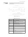
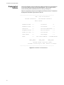
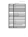
AT-FH812u AT-FH824u Fast Ethernet 10/100 Hubs USER’S GUIDE PN 613-10752-00 Rev. B Copyright © 1998 Allied Telesyn International, Corp. 950 Kifer Road, Sunnyvale CA 94086 USA All rights reserved. No part of this publication may be reproduced without prior written permission from Allied Telesyn International, Corp. Ethernet is a registered trademark of Xerox Corporation. SNMPc is a registered trademark of Castle Rock. UNIX is a registered trademark of X/ Open Company, LTD. Internet Explorer, Windows 95 and Windows NT are registered trademarks of Microsoft Corporation. Netscape Navigator is a registered trademark of Netscape Communications Corporation. All other product names, company names, logos or other designations mentioned herein are trademarks or registered trademarks of their respective owners. Allied Telesyn International, Corp. reserves the right to make changes in specifications and other information contained in this document without prior written notice. The information provided herein is subject to change without notice. In no event shall Allied Telesyn International, Corp. be liable for any incidental, special, indirect, or consequential damages whatsoever, including but not limited to lost profits, arising out of or related to this manual or the information contained herein, even if Allied Telesyn International, Corp. has been advised of, known, or should have known, the possibility of such damages. Table of Contents AT-FH812u and AT-FH824u Software . . . . . . . . . . . . . . . . . . . . . . . . . . . . . . . . . . . . . . . . . . . . . . . . . . . . . . . . . . . . . . . . . . 1 Introduction . . . . . . . . . . . . . . . . . . . . . . . . . . . . . . . . . . . . . . . . . . . . . . . . . . . . . . . . . . . . . . . . . . . . . . . . . . . . . . . . . . . . . . . . . . . . . . . . . . . . 1 Required Connections for System Configuration . . . . . . . . . . . . . . . . . . . . . . . . . . . . . . . . . . . . . . . . . . . . . . . . . . . . . . . . . . . . . 2 Connecting a VT100 Terminal . . . . . . . . . . . . . . . . . . . . . . . . . . . . . . . . . . . . . . . . . . . . . . . . . . . . . . . . . . . . . . . . . . . . . . . . . . . . . . . 2 Connecting a Modem . . . . . . . . . . . . . . . . . . . . . . . . . . . . . . . . . . . . . . . . . . . . . . . . . . . . . . . . . . . . . . . . . . . . . . . . . . . . . . . . . . . . . . . 2 Making a Telnet Connection . . . . . . . . . . . . . . . . . . . . . . . . . . . . . . . . . . . . . . . . . . . . . . . . . . . . . . . . . . . . . . . . . . . . . . . . . . . . . . . . 3 Connecting for an In-Band Network . . . . . . . . . . . . . . . . . . . . . . . . . . . . . . . . . . . . . . . . . . . . . . . . . . . . . . . . . . . . . . . . . . . . . . . . . 3 Configuring Your System with the Console Interface . . . . . . . . . . . . . . . . . . . . . . . . . . . . . . . . . . . . . . . . . . . . . . . . . . . . . . . . . 4 Using the System Configuration Program. . . . . . . . . . . . . . . . . . . . . . . . . . . . . . . . . . . . . . . . . . . . . . . . . . . . . . . . . . . . . . . . . . . . 5 Displaying System Information . . . . . . . . . . . . . . . . . . . . . . . . . . . . . . . . . . . . . . . . . . . . . . . . . . . . . . . . . . . . . . . . . . . . . . . . . . . . . . 7 Resetting the System . . . . . . . . . . . . . . . . . . . . . . . . . . . . . . . . . . . . . . . . . . . . . . . . . . . . . . . . . . . . . . . . . . . . . . . . . . . . . . . . . . . . . . . 8 Logging Off the System . . . . . . . . . . . . . . . . . . . . . . . . . . . . . . . . . . . . . . . . . . . . . . . . . . . . . . . . . . . . . . . . . . . . . . . . . . . . . . . . . . . . . 8 Performing Basic Configuration . . . . . . . . . . . . . . . . . . . . . . . . . . . . . . . . . . . . . . . . . . . . . . . . . . . . . . . . . . . . . . . . . . . . . . . . . . . . . 8 Changing the Network Configuration . . . . . . . . . . . . . . . . . . . . . . . . . . . . . . . . . . . . . . . . . . . . . . . . . . . . . . . . . . . . . . . . . . . . . . . 9 Assigning SNMP Parameters . . . . . . . . . . . . . . . . . . . . . . . . . . . . . . . . . . . . . . . . . . . . . . . . . . . . . . . . . . . . . . . . . . . . . . . . . . . . . . . 10 SNMP Communities. . . . . . . . . . . . . . . . . . . . . . . . . . . . . . . . . . . . . . . . . . . . . . . . . . . . . . . . . . . . . . . . . . . . . . . . . . . . . . . . . . . . . . . . 11 IP Trap Managers . . . . . . . . . . . . . . . . . . . . . . . . . . . . . . . . . . . . . . . . . . . . . . . . . . . . . . . . . . . . . . . . . . . . . . . . . . . . . . . . . . . . . . . . . . 12 Hub Configuration . . . . . . . . . . . . . . . . . . . . . . . . . . . . . . . . . . . . . . . . . . . . . . . . . . . . . . . . . . . . . . . . . . . . . . . . . . . . . . . . . . . . . . . . . 13 Hub Selection Menu . . . . . . . . . . . . . . . . . . . . . . . . . . . . . . . . . . . . . . . . . . . . . . . . . . . . . . . . . . . . . . . . . . . . . . . . . . . . . . . . . . . . . . . 13 Hub Configuration Menu . . . . . . . . . . . . . . . . . . . . . . . . . . . . . . . . . . . . . . . . . . . . . . . . . . . . . . . . . . . . . . . . . . . . . . . . . . . . . . . . . . 14 Configuring Port Parameters . . . . . . . . . . . . . . . . . . . . . . . . . . . . . . . . . . . . . . . . . . . . . . . . . . . . . . . . . . . . . . . . . . . . . . . . . . . . . . . 16 Defining Port Backups . . . . . . . . . . . . . . . . . . . . . . . . . . . . . . . . . . . . . . . . . . . . . . . . . . . . . . . . . . . . . . . . . . . . . . . . . . . . . . . . . . . . . 18 Configuring Port Security . . . . . . . . . . . . . . . . . . . . . . . . . . . . . . . . . . . . . . . . . . . . . . . . . . . . . . . . . . . . . . . . . . . . . . . . . . . . . . . . . . 19 RMON Configuration. . . . . . . . . . . . . . . . . . . . . . . . . . . . . . . . . . . . . . . . . . . . . . . . . . . . . . . . . . . . . . . . . . . . . . . . . . . . . . . . . . . . . . . 20 Downloading System Software. . . . . . . . . . . . . . . . . . . . . . . . . . . . . . . . . . . . . . . . . . . . . . . . . . . . . . . . . . . . . . . . . . . . . . . . . . . . . 21 Using the Serial Port to Download via Out-of-Band. . . . . . . . . . . . . . . . . . . . . . . . . . . . . . . . . . . . . . . . . . . . . . . . . . . . . . . . . . 22 Changing System Passwords . . . . . . . . . . . . . . . . . . . . . . . . . . . . . . . . . . . . . . . . . . . . . . . . . . . . . . . . . . . . . . . . . . . . . . . . . . . . . . . 23 Configuring the Out-of-Band Console . . . . . . . . . . . . . . . . . . . . . . . . . . . . . . . . . . . . . . . . . . . . . . . . . . . . . . . . . . . . . . . . . . . . . . 23 Displaying Statistics. . . . . . . . . . . . . . . . . . . . . . . . . . . . . . . . . . . . . . . . . . . . . . . . . . . . . . . . . . . . . . . . . . . . . . . . . . . . . . . . . . . . . . . . 23 Displaying Repeater Statistics . . . . . . . . . . . . . . . . . . . . . . . . . . . . . . . . . . . . . . . . . . . . . . . . . . . . . . . . . . . . . . . . . . . . . . . . . . . . . . 24 Displaying Hub Statistics . . . . . . . . . . . . . . . . . . . . . . . . . . . . . . . . . . . . . . . . . . . . . . . . . . . . . . . . . . . . . . . . . . . . . . . . . . . . . . . . . . . 25 Displaying Port Statistics . . . . . . . . . . . . . . . . . . . . . . . . . . . . . . . . . . . . . . . . . . . . . . . . . . . . . . . . . . . . . . . . . . . . . . . . . . . . . . . . . . . 26 Troubleshooting. . . . . . . . . . . . . . . . . . . . . . . . . . . . . . . . . . . . . . . . . . . . . . . . . . . . . . . . . . . . . . . . . . . . . . . . . . . . . . . . . . . . . . . . . . . 28 Network Management Access. . . . . . . . . . . . . . . . . . . . . . . . . . . . . . . . . . . . . . . . . . . . . . . . . . . . . . . . . . . . . . . . . . . . . . . . . . . . . . 28 Pin Assignments for Serial Port Connections . . . . . . . . . . . . . . . . . . . . . . . . . . . . . . . . . . . . . . . . . . . . . . . . . . . . . . . . . . . . . . . . 28 iii AT-FH812u and AT-FH824u Software Introduction The AT-FH812u and AT-FH824u hub (and the connected stack) is managed through a direct console or modem connection to the AT-FH801u network management agent module's serial port, using Telnet to access the hub over the network, a standard browser to access the Agent Module's embedded web agent, or with SNMP-based network management software. Once you connect a terminal or PC to the serial port on the hub, you can perform the following tasks: ❑ Enable/disable any port ❑ Set the communication mode for any port ❑ Configure SNMP parameters ❑ Select RMON options ❑ Configure port security ❑ Display system information or statistics ❑ Download system firmware ❑ Restart the system 1 AT-FH812u and AT-FH824u Software Required Connections for System Configuration The hub includes a menu-driven configuration program. The ASCII interface to this program is accessed by making a direct connection to the serial port on the Agent Module, or by a Telnet connection to the hub over the network. This section describes how to access the menu-driven configuration program via: ❑ Onsite connection — A terminal or workstation connected to the serial port locally on the Agent Module. ❑ Modem connection — A workstation connected to the serial port of a remote via modems. ❑ Telnet connection — A workstation connected to a remote hub via a Telnet connection through the network. It also describes how to access the embedded web agent over the network using any standard browser, or with network management software or other third-party mangement software. Connecting a VT100 Terminal Attach a VT100-compatible terminal, or a PC running a terminal emulation program, to the serial port on the Agent Module. Use the null-modem cable provided with this package, or a null modem connection that complies with the wiring assignments shown in the back of this guide. When attaching to a PC, make the following terminal settings: Connecting a Modem ❑ Terminal emulation type to VT100 ❑ Specify the port used by your PC, for example COM 1~4 ❑ Communications to 8 data bits, 1 stop bit, no parity, and 9600 bps (for initial configuration) ❑ Flow control to none Configure the Hub Site. Connect the Agent Module's DB9 serial port to the modem's serial port using standard cabling. For most modems, which use a 25-pin port, you will need to provide an RS232 cable with a 9-pin connector on one end and a 25-pin connection on the other end. You do not have to set the modem at the hub's site, because the hub will automatically configure it to auto-answer mode. Configure the Remote Site. At the remote site, connect the PC's COM port (COM 1~4) to the modem's serial port. Set terminal emulation type to VT100, specify the port used by your PC (COM 1~4), and then set communications to 8 data bits, 1 stop bit, no parity, 9600 bps and no flow control. 2 AT-FH812u and AT-FH824u User’s Guide Making a Telnet Connection Before you access the hub via an in-band Telnet connection or with a Web browser, you must first configure it with a valid IP address, subnet mask and default gateway, using an out-of-band connection or BootP protocol. Once the hub's IP parameters are configured, you can access the on-board configuration program from anywhere within the attached network. Note Use the Network Configuration menu to specify the maximum number of simultaneous Telnet connections supported by the system. Connecting for an In-Band Network The on-board configuration program can be accessed by running Telnet or a web browser (Internet Explorer 3.0 or above, or Netscape Navigator 3.0 or above) from any computer attached to the network. It can also be managed from a computer using network management software. However, prior to accessing the hub (or connected stack), you must first configure it with a valid IP address, subnet mask, and default gateway using an out-of-band connection or BootP protocol. Note The on-board program only provides access to basic configuration functions. To access the full range of SNMP mangement functions, you must use SNMP-based network mangement software. 3 AT-FH812u and AT-FH824u Software Configuring Your System with the Console Interface Once a direct connection to the serial port or a Telnet connection is established, the login screen for the on-board configuration program appears, as shown in Figure 1. -----------------------------------------------------------FH824U/FH812U Dual-Speed Intelligent Hub User Interface V0.09 06-08-98 (C) Copyright Allied Telesyn International, Corp. User Name : admin Password : ***** Press <Ctrl+E> to exit this program. ------------------------------------------------------------ Figure 1 Login Screen for On-Board Configuration Program When you first log into the configuration program, the default user names are admin and guest and passwords are null. The administrator has Read/Write access to all configuration parameters and statistics. A guest has Read Only access to the management program. Type admin for the user name and press <Enter> for the password to open the Main Menu. Be sure to define a password, record it and put it in a safe place. To define your password, select User Passwords from the Main Menu and enter a password. Note that passwords can consist of up to 14 alphanumeric characters and are not case sensitive. Configuration parameters are described in the following section. Note A user is allowed three attempts to enter the correct password; on the third failed attempt the current connection is terminated. 4 AT-FH812u and AT-FH824u User’s Guide Using the System Configuration Program The system configuration program lets you define system parameters; manage and control the hub, the connected stack and all its ports; and monitor network conditions. Figure 2 and the Table 1 briefly describe the selections available from this program. Note Options for the currently selected item are displayed in the highlighted area at the bottom of the interface screen. ------------------------------------------------------------------------------------Main Menu System Information ... Restart Hub ... Exit Configuration Panels System Configuration ... SNMP Configuration ... Hub Configuration ... Port Configuration ... RMON Configuration ... TFTP Download ... Xmodem Download ... User Password ... Console Configuration ... Statistics Panels Repeater Statistics ... Hub Statistics ... Port Statistic ... Display or work with system information. Use TAB or Cursor keys to move, <Enter> to confirm. ------------------------------------------------------------------------------------Figure 2 Main Menu, System Configuration Program 5 AT-FH812u and AT-FH824u Software Table 1 System Configuration Commands Menu Description System Information Provides system description, including MIB identifier and other data. Restart Hub Resets management agent for all hubs in stack or for selected hub. Exit Exits the configuration program. Configuration Panels System Configuration Configures IP parameters, including address, subnet mask, gateway, SLIP IP, default bootup IP, and maximum number of Telnet sessions. SNMP Configuration Configures communities and trap managers. Hub Configuration Displays hardware/firmware versions for hub, isolates/attaches hub's repeater segments, and shows if Agent Module or Internal Switch Module are installed. If Agent Module is installed, shows its bootup option, MAC address and hardware/ firmware versions. If Internal Switch Module is installed, displays its hardware version and shows if enabled/disabled. Port Configuration Disables/enables any port; sets communication mode to 10 or 100 Mbps, or auto-negotiation. RMON Configuration Enables/disables RMON for 10 or 100 Mbps segments, attaches Agent Module to 10 or 100 Mbps segment, and activates full 9 RMON groups for the segment the Agent Module is attached to. TFTP Download Downloads new firmware version to update Agent Module over the network. XMODEM Download Downloads new firmware to update Agent Module via a console interface. User Passwords Sets Administrator and Guest names and passwords used for system access. Console Configuration Sets console time-out, and refresh period for displayed statistics. Statistics Panels 6 Repeater Statistics Displays network performance for 10 and 100 Mbps stack segments. Hub Statistics Displays network performance for each hub in the stack. Port Statistics Displays network performance for the selected port. AT-FH812u and AT-FH824u User’s Guide Displaying System Information Use the System Information screen to display descriptive information about the hub, or for quick system identification, as shown in Figure 3 and Table 2. -----------------------------------------------------------System Information System Description : CentreCOM FH812U System Object ID : 1.3.6.1.4.1.259.5.7 System Up Time : 134367 (0 day 0 hr 22 min 23 sec) System Name : dual-speed hub Contact : system administrator Location : headquarters <APPLY> <OK> <CANCEL> The name of this system. <Ctrl-F> forward a char, <Ctrl-B> backward a char. ------------------------------------------------------------ Figure 3 System Information Screen Note Pressing the <APPLY> button makes all changes permanent by writing them to EEPROM. Pressing <OK> implements all changes temporarily--these changes will be voided if the system is reset. Pressing <CANCEL> will drop any changes as long as the <APPLY> or <OK> buttons have not been pressed, and will exit to the parent menu. Table 2 System Information Parameters Parameter Description System Description System hardware description. System Object ID Object identifier for the hub's network management subsystem as defined in MIB II. System Up Time Length of time the current management agent has been running. (Note that the first value is seconds.) System Name1 Name assigned to the hub system. Contact2 Contact person for the system. Location 3 Specifies the area or location where the system resides. 1, 2, 3: Maximum string length is 255, but the screen only displays 44 characters. You can use the arrow keys to browse the whole string. 7 AT-FH812u and AT-FH824u Software Resetting the System Logging Off the System Performing Basic Configuration Use the Reset command under the Main Menu to reset the agent. Use the Exit command under the Main Menu to exit the configuration program and terminate communications with the switch for the current session. After initially logging onto the system, use the Configuration Menu to adjust the communication parameters for your console to ensure a reliable connection. Next, set the Administrator and Guest passwords. Remember to record them in a safe place. If you want to manage the hub with in-band management software, then you also need to set the community string, which controls access to the Agent Module. The other items provided by the Configuration Menu are used to set specific communication parameters for individual ports, enable RMON options, and configure backup ports. Each setup screen provided by the Configuration menu is described in the following sections. 8 AT-FH812u and AT-FH824u User’s Guide Changing the Network Configuration Use the Network Configuration screen to configure the hub's Internet Protocol (IP) parameters, set the bootup option, and define the maximum number of Telnet sessions allowed. Table 3 defines the screen’s parameters listed in Figure 4. -----------------------------------------------------------------System Configuration Current Used New Setting ---------------------------------------------------IP Address : 10.1.113.115 10.1.113.115 Subnet Mask : 255.255.0.0 255.255.0.0 Gateway IP : 0.0.0.0 0.0.0.0 SLIP IP : 0.0.0.0 0.0.0.0 Bootup IP : 0.0.0.0 0.0.0.0 MAX # of allowed Telnet sessions (0 - 2) : 2 <APPLY> <OK> <CANCEL> The new IP address. <Ctrl-F> forward a char, <Ctrl-B> backward a char. ----------------------------------------------------------- Figure 4 System Configuration Example Table 3 Network Configuration Parameters Parameters Description IP Address IP address of the agent you are managing. The Agent Module supports SNMP over UDP/IP transport protocol. In this environment, all systems on the Internet, such as network interconnection devices and any PC accessing the Agent Module, are assigned an IP address. Valid IP addresses consist of four numbers, from 0 to 255, separated by periods. Anything outside of this format will not be accepted by the configuration program. (The default address is 0.0.0.0.) Subnet Mask Subnet mask of the agent you have selected. This mask identifies the host address bits used for routing to specific submits. (The default subnet mask is 0.0.0.0.) Default Gateway Gateway used to pass trap messages from the hub's agent to the management station. Note that the gateway must be defined if the management station is located in a different IP segment. (The default gateway is 0.0.0.0.) SLIP IP IP address used to access the configuration program via an out-of-band SLIP connection to the serial port on the Agent Module. Bootup IP The default IP address assigned to this agent. This address is used only until you assign a new address to the agent, or after downloading new firmware to the Agent Module. Max # of allowed The maximum number of Telnet sessions allowed to simultaneously access the Agent Module. 9 AT-FH812u and AT-FH824u Software Assigning SNMP Parameters Use the SNMP Configuration screen to display and modify parameters for the Simple Network Management Protocol (SNMP). The Agent Module monitors the hardware status of the hub (or connected stack), as well as the traffic passing through the ports. A Network Management Station (NMS) can access this information using other third-party network management software. Access rights to the agent are controlled by community strings. To communicate with the agent, the NMS must first submit a valid community string for authentication. The options for configuring community strings and related trap functions are described in Figure 5, Figure 6 and Figure 7, and in Table 4, Table 5 and Table 6: -----------------------------------------------------------------SNMP Configuration Send Authentication Fail Trap : YES SNMP Communities ... IP Trap Managers ... <APPLY> <OK> <CANCEL> Send a trap or not when SNMP authentication fails. Use TAB or Cursor keys to move, <Space> to select. ------------------------------------------------------------------ Figure 5 SNMP Configuration Table 4 SNMP Parameters 10 Parameters Description Send Authentication Issue a trap message whenever authentication of an SNMP request fails. Fail Traps The default issues traps to specified IP trap managers. SNMP Communities Assigns SNMP access based on specified community strings. IP Trap Managers Specifies management stations that will receive authentication failure messages or other trap messages from the hub. AT-FH812u and AT-FH824u User’s Guide SNMP Communities SNMP Communities Community Name Access Status READ/WRITE Enabled 1. public 2. READ-ONLY Disabled 3. READ-ONLY Disabled 4. READ-ONLY Disabled 5. READ-ONLY Disabled <APPLY> <OK> <CANCEL> The name of this SNMP community entry. <Ctrl-F> forward a char, <Ctrl-B> backward a char. ------------------------------------------------------------------------------------Figure 6 SNMP Communities Table 5 SNMP Communities Parameters Parameters Description Community Name1 A community string authorized for SNMP or trap management access (maximum of 20 characters). Access Management access is restricted to Read Only or Read/Write. Status Indicates operational status of the community as Enabled or Disabled. 1. This hub provides a default community string of “public” with Read/Write access. 11 AT-FH812u and AT-FH824u Software IP Trap Managers IP Trap Managers IP Address Community Name Status 1. 0.0.0.0 public Disabled 2. 0.0.0.0 public Disabled 3. 0.0.0.0 public Disabled 4. 0.0.0.0 public Disabled 5. 0.0.0.0 public Disabled 6. 0.0.0.0 public Disabled 7. 0.0.0.0 public Disabled 8. 0.0.0.0 public Disabled 9. 0.0.0.0 public 10. Disabled 0.0.0.0 public <APPLY> Disabled <OK> <CANCEL> The IP address of this IP trap manager entry. <Ctrl-F> forward a char, <Ctrl-B> backward a char. ------------------------------------------------------------ Figure 7 IP Trap Managers Table 6 IP Trap Manager Parameters 12 Parameters Description IP Address IP address of the trap manager. IP Address of the Trap Manager The community string required for trap management access (20 characters max). Status Indicates status of the entry as Enabled or Disabled. AT-FH812u and AT-FH824u User’s Guide Hub Configuration Hub Selection Menu Use the Hub Configuration screen to configure any hub in the stack. This menu is used to configure the selected hub, as well as the Agent Module. Use the menu in Figure 8 to view a basic description of all the hubs in the stack, including hardware and firmware version numbers, or to open a more detailed configuration screen for a specific hub. The information provided in Figure 8 is described in Table 7 and Table 8, and in Figure 9: -----------------------------------------------------------Hub Configuration: Hub Selection Menu Hub H/W EPROM ID Version F/W Ver FLASH PORT SNMP Switch Detailed F/W Ver Number Agent Module Screen --------------------------------------------------------------1. 1 0.11 0.03 24 Master None <GO> <PREV_PANEL> Go to hub configuration detailed screen. Use TAB or Cursor keys to move, <Enter> to confirm. ------------------------------------------------------------ Figure 8 Hub Selection Menu Table 7 Hub Selection Parameters Parameters Description Hub ID Hub identifier in stack. (Up to 6 hubs may be connected via the stack cable.) H/W version Hardware version number of the repeater board. EPROM F/W ver Version number of the repeater firmware in permanent memory. Flash F/W ver Version number of the repeater firmware in temporary memory. Port Number Indicates whether this device has 12 or 24 repeater ports. SNMP Agent Indicates whether an Agent Module is installed in this hub. Switch Module Indicates whether an Internal Switch Module is installed in this hub. 13 AT-FH812u and AT-FH824u Software Hub Configuration Menu -----------------------------------------------------------Hub Configuration Hub ID : 1 Serial No : 11-00-00-00-10-24 H/W Ver : 1 # of Port : 24 10M BackPlane : Attached 100M BackPlane: Attached SNMP Agent ===================================================== Baudrate : 9600 H/W Ver Bootup Option : Normal MAC Address 00-00-E8-61-1B-C8 : : 1 POST Ver : 0.11 System Ver : 0.03 Switch Module ===================================================== Type : Not-Present <APPLY> <OK> <CANCEL> 10M segment backplane isolation status. Use TAB or Cursor keys to move, <Space> to select. ------------------------------------------------------------ Figure 9 Hub Configuration, Including SNMP Agent and Switch Module 14 AT-FH812u and AT-FH824u User’s Guide Table 8 Hub Configuration Parameters Parameters Description Hub Hub ID Hub identifier in stack. Serial No Serial number of this hub. 10M Backplane Attaches/isolates hub's 10 Mbps repeater bus from the stack's data channel. 100M Backplane Attaches/isolates hub's 100 Mbps repeater bus from the stack's data channel. H/W Ver Hardware version number of the repeater board. # of Ports Indicates whether this device has 12 or 24 repeater ports. SNMP Agent Baudrate Rate at which data is sent between the Agent Module's serial port and the connected device. Supported baud rates are 9600, 19200 and 38400 bps. Bootup Option Specifies whether or not IP functionality is enabled (via manual configuration), set by Boot Protocol (BootP), or disabled. Options include: IP Enabled - IP functionality is enabled based on the default or configured settings. (The default is IP Enabled.) BootP Get IP - IP is enabled but will not function until a BootP reply has been received. BootP requests will be periodically broadcast by the hub in an effort to learn its IP address. MAC Address Physical address of the Agent Module. H/W Version Hardware version number of the Agent Module. POST Ver Version number of the Agent Module's Power-on Self-test. System Ver System firmware version. Switch Module Type Indicates if an internal switch or media extension module is installed. 15 AT-FH812u and AT-FH824u Software Configuring Port Parameters Select Administrative Status Control from the Port Configuration screen to configure any port on the hub. The following menu shows the configuration options. In addition to the functional parameters listed in Figure 10, note that you can also enable/disable any port. Table 9 lists and defines the Port Administration Status control parameters. -----------------------------------------------------------Port Administration Status Control (1 - 12) Hub ID : 1 Port Admin State Link State Partition Mode Speed -----------------------------------------------------------1. Enabled Connected Not-Partition Auto 100M 2. Enabled Connected Not-Partition Auto 100M 3. Enabled Connected Not-Partition Auto 100M 4. Enabled Not-Partition Auto 5. Enabled Connected Not-Partition Auto 100M 6. Enabled Connected Not-Partition Auto 10M 7. Enabled Connected Not-Partition Auto 100M 8. Enabled Connected Not-Partition Auto 10M Connected 100M 9. Enabled Connected Not-Partition Auto 100M 10. Enabled Connected Not-Partition Auto 100M 11. Enabled Not-Connected Not-Partition Auto 10M 12. Enabled Not-Partition Auto 100M Connected <APPLY> <OK> <CANCEL> <PORT_13_24> The administrative status of port. Use TAB or Cursor keys to move, <Space> to select. ------------------------------------------------------------ Figure 10 Port Administration Status Control Note If a port is disabled by an intrusion action, you must disable it manually in the Administration Status menu, then re-enable it to restore the connection. See Configuring Port Security on page 19. 16 AT-FH812u and AT-FH824u User’s Guide Table 9 Port Administration Status Control Parameters Parameters Description Admin State Allows you to disable a port due to abnormal behavior (e.g., excessive collisions), and then re-enable it after the problem has been resolved. You may also disable a port for security reasons. Link State Indicates if the port has a valid connection to an external device. Partition Indicates if the port is partitioned. Mode Sets the transmission speed to 10 Mbps, 100 Mbps or autodetection. Speed Indicates the transmission speed currently used by this port. 17 AT-FH812u and AT-FH824u Software Defining Port Backups Select Backup Link Control (described in Table 10) from the Port Configuration screen to define up to 15 master/slave port pairs. If the connection to the master port fails, the slave port will automatically take over. For greater reliability, primary and secondary ports should be located on different hubs. Use the menu in Figure 11 to specify and activate port backup pairs. -----------------------------------------------------------Backup Link Control Set Primary Port Secondary Port Action Status 1. Hub: 1 Port: 1 Hub: 1 Port: 12 Active Inactive 2. Hub: 1 Port: 1 Hub: 1 Port: 2 Inactive Inactive 3. Hub: 1 Port: 1 Hub: 1 Port: 2 Inactive Inactive 4. Hub: 1 Port: 1 Hub: 1 Port: 2 Inactive Inactive 5. Hub: 1 Port: 1 Hub: 1 Port: 2 Inactive Inactive 6. Hub: 1 Port: 1 Hub: 1 Port: 2 Inactive Inactive 7. Hub: 1 Port: 1 Hub: 1 Port: 2 Inactive Inactive 8. Hub: 1 Port: 1 Hub: 1 Port: 2 Inactive Inactive 9. Hub: 1 Port: 1 Hub: 1 Port: 2 Inactive Inactive 10. Hub: 1 Port: 1 Hub: 1 Port: 2 Inactive Inactive 11. Hub: 1 Port: 1 Hub: 1 Port: 2 Inactive Inactive 12. Hub: 1 Port: 1 Hub: 1 Port: 2 Inactive Inactive 13. Hub: 1 Port: 1 Hub: 1 Port: 2 Inactive Inactive 14. Hub: 1 Port: 1 Hub: 1 Port: 2 Inactive Inactive 15. Hub: 1 Port: 1 Hub: 1 Port: 2 Inactive <APPLY> <OK> Inactive <CANCEL> The primary hub ID for this backup set. <Ctrl-F> forward a char, <Ctrl-B> backward a char. --------------------------------------- Figure 11 Port Backup Link Control Table 10 Backup Link Control Parameters 18 Parameters Description Backup Set Identifier for up to 15 backup port pairs. Primary Port Pair member serving as the primary link. Hub Hub ID for the master port. Port Port identifier for the master port. Secondary Port Pair member serving as the backup link. Hub Hub ID for the slave port. Port Port identifier for the slave port. Action Each backup pair can be set to Active or Inactive. Status Active is displayed if the backup port has taken over the link. Inactive is displayed if the primary port is still handling the link. AT-FH812u and AT-FH824u User’s Guide Configuring Port Security Select Port Security Control from the Port Configuration screen to configure port intrusion protection. The parameters are described in Figure 12 and Table 11. ------------------------------------Port Security Control (1 - 12) Hub ID : 1 Port Mode Auth. Address L.S. Address Intrusion Action 1. MANUAL 0000e8-123456 0000e8-123456 WARNING & DISABLE 2. AUTO 0000e8-123798 0000e8-123798 WARNING & DISABLE 3. AUTO 0000e8-527456 0000e8-527456 INACTIVE 4. 000000-000000 5. 000000-000000 6. 000000-000000 7. 000000-000000 8. 000000-000000 9. 000000-000000 10. 000000-000000 11. 000000-000000 12. 000000-000000 <APPLY> <OK> <CANCEL> <PORT_13_24> The authorized address assignment mode of the port. Use TAB or Cursor keys to move. <Space> to select. ------------------------------------Figure 12 Port Security Control Parameters (from Port Configuration Screen) Table 11 Definition of Port Security Control Parameters Name Description Mode AUTO - Copies authorized address from currently attached device. MANUAL - Allows administrator to enter authorized address by hand. Auth. Address MAC address of device authorized to access this port. LS. Address MAC address of the last device attached to this port. Intrusion Action Any of the following actions can be selected if intrusion is detected: INACTIVE - Detection disabled. WARNING AND DISABLE - Sends message to Trap Managers and disables violated port. Enabling a Port. To enable a port that has been disabled by an intrusion: (1.) Manually disable it in the Administration Status menu. (2.) Re-enable it again. These two steps will restore the connection. (See Note on Configuring Port Parameters on page 16.) 19 AT-FH812u and AT-FH824u Software RMON Configuration Use the RMON Configuration screen (Figure 13) to enable/disable RMON support or to attach the Agent Module to either the 10 or 100 Mbps segment. Table 12 describes the RMON configuration parameters. -----------------------------------------------------------RMON Configuration 10M Segment RMON 100M Segment RMON : Disable : Enable Full Segment Enable : NO Agent Attached to : 100M <APPLY> <OK> <CANCEL> Use ESC for help. Use arrow keys to move. <Enter> to confirm. ------------------------------------------------------------ Figure 13 RMON Configuration Screen Table 12 RMON Configuration Parameters Parameters Description 10M Segment RMON Enable/disable RMON support for 10 Mbps segment. 100M Segment RMON Enable/disable RMON support for 100 Mbps segment. Full Segment Enable If RMON is enabled for the segment attached to the Agent Module, and this option is set to YES, then all 9 RMON groups are used. If this option is set to NO, only RMON groups 1, 2, 3 and 9 are used. Agent Attached to1 Attach the Agent Module to either the 10 or 100 Mbps segment. Note that only the segment attached to the agent can provide full RMON support. 1. If no path exists between the two repeater segments via an Internal Switch Module or by other external network connections, then the SNMP, HTTP and Telnet protocols will only have management access to the repeater segment attached to the Agent Module. Note To use the functions provided by RMON, you must access the hub's agent with an SNMP management program that supports RMON. 20 AT-FH812u and AT-FH824u User’s Guide Downloading System Software Using TFTP Protocol to Download over the Network. Use the TFTP Download menu to load software updates into the hub. The download file should be an atiflash.bin binary file from Allied Telesyn; otherwise the agent will not accept it. The success of the download operation depends on the accessibility of the TFTP server and the quality of the network connection. After downloading the new software, the agent will automatically restart itself. Parameters shown on this screen are indicated in Figure 14 and Table 13. -----------------------------------------------------------TFTP Download Download Server IP : 10.1.113.21 Download filename : tomcat.bin Download Mode : Upgrade Flash & Reboot Start TFTP Download <APPLY> <OK> <CANCEL> The IP address of TFTP server. <Ctrl-F> forward a char, <Ctrl-B> backward a char. ------------------------------------------------------------ Figure 14 TFTP Download Parameters Table 13 TFTP Download Parameters Defined Parameters Description Download Server IP IP address of a TFTP server. Download Filename The atiflash.bin binary file to download. Download Mode You can download to permanent flash ROM or temporary storage in RAM (for test purposes). However, if you download to temporary memory, this firmware will be lost upon power off. To update new agent firmware for permanent use, it must be downloaded to flash ROM. Start TFTP Download Issues request to TFTP server to download the specified file. 21 AT-FH812u and AT-FH824u Software Using the Serial Port to Download via Out-of-Band Use the XModem Download command to update available software in the hub. The download file should be the atiflash.bin binary file from Allied Telesyn; otherwise the agent will not accept it. This command specifies direct download from an attached device via the serial port. You may download using any terminal emulation program that can transmit binary files using XModem protocol. The parameters shown in this screen are indicated in Figure 15 and Table 14. -----------------------------------------------------------XMODEM Download Download Mode : Upgrade DRAM & Reboot Start XMODEM Download Use ESC for help. Use arrow keys to move. Use TAB or Cursor keys to move, <Space> to select. ------------------------------------------------------------ Figure 15 XModem Download Parameters Table 14 Xmodem Download Parameters Defined Parameters Description Download Mode You can download to permanent flash ROM or temporary storage in RAM (for test purposes). However, if you download to temporary memory, this firmware will be lost upon power off. To update new agent firmware for permanent use, it must be downloaded to flash ROM. Start Download Waits to receive specified file from the TFTP server. To start the download process, use XModem protocol and select a file. Start sending the file from your computer by specifying send or upload file with the XModem facility. The terminal emulation program will display the progress of the download process. After downloading the new software, the agent will automatically restart itself. 22 AT-FH812u and AT-FH824u User’s Guide Changing System Passwords The User Passwords screen is used to display or modify user names and passwords for the on-board configuration program. There are two user types: Administrator and Guest. Only the Administrator has write access for parameters governing the SNMP agent. You should, therefore, assign a user name and password to the Administrator as soon as possible, and store it in a safe place. Passwords can consist of up to 14 alphanumeric characters and are not case sensitive. The configuration program will allow a user three attempts at entering a password before locking the user out by terminating the connection. If for some reason your password is lost, or you can not gain access to the System Configuration Program, contact Allied Telesyn tech support for assistance. System password parameters are defined in Table 15. Table 15 System Password Parameters Parameters Description Admin name: admin Administrator has access privilege of Read/Write for all screens. Password: null Guest name: guest Guest has access privilege of Read Only for all screens. Password: null Configuring the Out-of-Band Console The Console Configuration screen is used to configure the console connected to the hub's serial port. The console parameters are described in Table 16. Table 16 Out-of-Band Console Parameters Parameters Description Lockout Status Enables/disables the lockout function. Lockout Delay Time If no input is received from the attached device after this interval (in minutes), the current session is closed. Range: 0 - 99 minutes. Default is 10 minutes. Auto-Refresh Period Specifies the interval at which statistics are read from the hub. Options: 30, 60, 120, 180, 300 seconds. Default is 30 seconds. Displaying Statistics The Statistics section on the Main Menu provides data on traffic passing through the stack segments, hubs, ports, and each of the optional media modules. The statistics these screens provide are described in the following sections. 23 AT-FH812u and AT-FH824u Software Displaying Repeater Statistics Use the Repeater Statistics screen to display statistics for the 10 Mbps and 100 Mbps stack segments. These values can be used to indicate the approximate loading for each segment, as shown in Figure 16 and defined in Table 17. -----------------------------------------------------------Repeater Statistics Refresh Statistics Auto-Refresh Statistics Reset Counter 10M Segment 100M Segment Frames : 1391288 1391288 Bytes : 1 Collisions : 267 0 Aligment Errors : 0 0 CRC Errors : 0 0 Total Errors : 6219780 6219780 0 <PREV_PANEL> Refresh current statistics screen. Use TAB or Cursor keys to move, <Enter> to confirm. ------------------------------------------------------------ Figure 16 Repeater Statistics Screen Table 17 Repeater Statistics Parameters 24 Parameters Description Refresh Statistics Refresh the displayed statistics. Auto-Refresh Statistics Refresh statistics at the interval specified in Console Configuration. Frames Number of frames passing through this device. Bytes Number of bytes passing through this device. Collisions Number of simultaneous node transmissions detected by this device. Alignment Errors Number of mis-synchronized data packets detected by this device. CRC Errors Number of Ethernet Cyclic Redundancy Check errors detected by this device. Total Errors Total number of errors, including FCS, alignment, FramesTooLong, ShortEvents, LateEvents, Jabber, and DataRateMismatches detected on this device. AT-FH812u and AT-FH824u User’s Guide Displaying Hub Statistics Use the Hub Statistics screen to display key statistics for each hub in the stack. Overall statistics on the traffic passing through each hub are displayed. See Figure 17 and Table 18. -----------------------------------------------------------Hub Statistics Refresh Statistics Hub ID Auto-Refresh Statistics Aligment Frames Bytes Collisions Errors CRC Total Errors Errors ----------------------------------------------------------------1. 1 1026288 267 0 0 1391289 <RESET> <PREV_PANEL> Refresh current statistics screen. Use TAB or Cursor keys to move, <Enter> to confirm. ------------------------------------------------------------ Figure 17 Hub Statistics Screen Table 18 Hub Statistics Parameters Parameters Description Refresh Statistics Refresh the displayed statistics. Auto-Refresh Statistics Refresh statistics at the interval specified in Console Configuration. Hub ID Hub identifier within the stack. Position The physical position in the stack (as determined by its position from the top of the stack). Frames Number of frames passing through this device. Bytes Number of bytes passing through this device. Collisions Number of simultaneous node transmissions detected by this device. Alignment Errors Number of mis-synchronized data packets detected by this device. CRC Errors Number of Ethernet Cyclic Redundancy Check errors detected by this device. Total Errors Total number of errors, including FCS, alignment, FramesTooLong, ShortEvents, LateEvents, Jabber, and DataRateMismatches detected on this device. 25 AT-FH812u and AT-FH824u Software Displaying Port Statistics Use the Port Statistics screen to display key statistics for each port. Overall statistics on the traffic passing through each port are displayed. This information can be used to identify potential problems with the hub (e.g., a faulty port). Select the required port from the Port Statistics: Port Selection Menu. The statistics displayed are indicated in Figure 18 and Table 19. -----------------------------------------------------------Hub 1 Refresh Statisttics Port 24 Statistics Auto-Refresh Statistics Reset Counter Readable Frames : 0 Collisions :0 Readable Octets : 0 Late Events : 0 CRC Errors : 0 Data Rate Mismatches : 0 Alignment Errors : 0 Auto Partitions : 0 Frames Too Long : 0 Total Errors : 0 Short Events : 0 LSA Changes : 0 Runts : 0 Last Source Address <PREV_PANEL> <PREV_PORT> : 00-00-E8-90-1B73 <NEXT_PORT> Refresh current statistics screen. Use TAB or Cursor keys to move, <Enter> to confirm. ------------------------------------------------------------ Figure 18 Port Statistics: Port Selection Menu 26 AT-FH812u and AT-FH824u User’s Guide Table 19 Port Statistics Statistics Description Refresh Statistics Refresh the displayed statistics. Auto-Refresh Statistics Refresh statistics at the interval specified in Console Configuration. Reset Counter Reset the statistics counter for all items to zero. Readable Frames Number of good frames received. Readable Octets Number of good octets received. CRC Errors Number of CRC errors. Alignment Errors For 10Mbps ports, the counter records alignment errors (missynchronized data packets). For 100Mbs ports, the counter records the sum of alignment errors and code errors (frames received with rxerror signal). Frames Too Long Number of times frame length has exceeded the maximum allowable size (i.e., 1518 bytes). Short Events Number of short fragments. Runts Number of fragments (that were too long to qualify as short events). Collisions Number of simultaneous node transmissions detected by this device. Late Events Number of frames where a collision occurred late in the transmission. Data Rate Mismatches Number of frames for which the data rate does not match the local frequency. Auto Partitions Number of times this port has been automatically partitioned due to jabber. Total Errors Total number of errors, including FCS, alignment, FramesTooLong, ShortEvents, LateEvents, Jabber, and DataRateMismatches detected on this device. LSA Changes Number of times the source address has changed. Last Source Addr. Last source address. 27 AT-FH812u and AT-FH824u Software Troubleshooting Refer to the AT-FH812u and AT-FH824u Installation Guide for a more detailed listing of troubleshooting procedures. However, if you have trouble making a connection via Telnet or accessing the web or SNMP agent, then please refer to the following section. Network Management Access You can access the hub from anywhere within the attached network. However, you must first configure the hub with a valid IP address, subnet mask, and default gateway. If you have trouble establishing a link to the console interface (with Telnet), the web agent (with a browser), or the SNMP agent (with network management software), check to see if you have a valid network connection. Then verify that you entered the correct IP address from your location. Also, be sure the port through which you are connecting to the hub has not been disabled. For detailed information, see Configuring Port Parameters on page 16. If it has not been disabled, then check the network cabling that runs between your management site and the hub. Pin Assignments for Serial Port Connections 28 DB9 Serial Port Pin Description. The DB9 serial port on the back panel is used to connect the hub to a management device. The on-board menu-driven configuration program can be accessed from a terminal, a PC running a terminal emulation program, or from a remote location via a modem connection. You can use the management port to configure port settings (enabled or disabled), or to update device firmware.