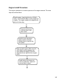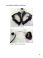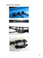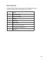
1
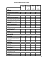
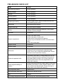
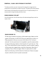
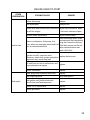
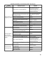
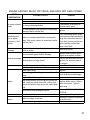
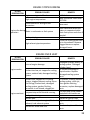
AQUANAMI POWERBOARD SERVICE MANUAL Version 1.0 2011 jetSurf jetKayak jetNami AQUANAMI, All Rights Reserved, 2011 This SERVICE MANUAL utilizes the following symbols: The Safety Alert Symbol means ATTENTION! A potential personal injury hazard. WARNING Indicates a potentially danger! Failure to follow WARNING instructions could result in serious injury or death. CAUTION: Indicates special precaution, if not followed, could severely damage the machine. NOTE: Provides key information to make information clearer. WARNING For your safety, understand and follow all the safety precautions and instructions contained in this SERVICE’S MANUAL. Failure to do so can result in SEVERE INJURY OR DEATH. If you have any questions or concerns about this service manual, please contact us or visit our web site at www.aquanami.com. 2 SAFETY NOTICE This manual has been prepared as a guide to service and repair Aquanami Powerboards. This edition was primarily published to be used by watercraft mechanical technicians who are already familiar with service procedures relating to watercraft. Mechanical technicians should attend training courses given by Aquanami. Please note that the instructions will apply only if proper hand tools and special service tools are used. The content depicts parts and/or procedures applicable to the particular product at time of writing. The sole purpose of the illustrations throughout the manual, is to assist identification of the general configuration of the parts. They are not to be interpreted as technical drawings or exact replicas of the parts. WARNING For your safety, understand and follow all the safety precautions and instructions contained in this SERVICE MANUAL. Failure to do so can result in SEVERE INJURY OR DEATH. WARNING Engine should be turned off and cold for all maintenance and repair procedures Although the mere reading of such information does not eliminate the hazard, your understanding of the information will promote its correct use. Always use common shop safety practice. AQUANAMI disclaims liability for all damages and/or injuries resulting from the improper use of the contents. We strongly recommend that any services be carried out and/or verified by a highly skilled professional mechanic. It is understood that certain modifications may render use of the watercraft illegal under existing federal, provincial and state regulations. 3 TABLE OF CONTENTS SAFETY NOTICE .. .. ... .. ... .. .. ... .. .. ... .. .. ... .. .. ... .. .. ... .. .. .. 3 INTRODUCTION .. .. ... .... ... .. .. ... .. .. ... .. .. ... .. .. ... .. .. ... .. .. .. 5 MAINTENANCE CHART. .. . .. . . .. . . .. . . .. . . .. . .. . . .. . . .. . . .. . . .. . . .. 7 PRESEASON PREPARATION. . . ... . .. . . .. . . .. . . . .. . . .. . . . . . .. . .. . . .. . . .. 10 STORAGE PROCEDURES. . . .. . .. . . .. . . .. . . .. . . .. . . .. . . .. . . .. . . .. . . .. 12 SPECIAL PROCEDURES. .. . . .. . . . .. . . .. . . .. . . .. . ... . . .. . . .. . . .. . . . . 24 POWER PLANT SPECIFICATION. .. . . .. . . . .. . . .. . . .. . . .. . ... . . .. . . .. . . .. . . . . 29 TROUBLESHOOTING. . .. . . ... .. . . .. . . .. . . .. . . . . .. . . .. . . . .. . . .. . . 31 ENGINE WILL NOT START . . .. ... .. .. . .. .. . .. .. . .. .. . .. .. . .. 32 ENGINE HARD TO START.. . .. .. . . .. . .. .. . .. .. . .. .. . .. .. . .. 35 ENGINE MISFIRES, RUNS IRREGULARLY.. .. .. . ... .. .. . .. . .. .. . .. .. . .. .. . .. 36 ENGINE CAN NOT REACH TOP SPEED. . .. .. . .. .. . .. .. . .. .. . .. .. . .. .. . .. 37 ENGINE STOPS RUNNING. . .. .. . .. .. . .. .. . .. .. . .. .. . .. .. . .. 38 ENGINE OVERHEATS.. . .. .. . .. .. . .. . . .. .. . .. .. . .. .. . .. 38 THROTTLE CABLE NOT RETURN BACK FULLY . .. .. . .. .. . .. . . .. .. . .. .. . .. .. . .. 39 STICKY STEERING.. . .. .. .. . .. .. .. . .. .. . .. .. . .. .. . .. 39 ABNORMAL VIBRATION AND WATER IN BILGE. .. . .. .. . .. .. . .. .. .. . .. .. . .. .. . .. 39 PROPULSION .. . .. .. .. . .. .. … .. . .. .. .. . .. .. . .. .. . .. .. . .. .. . .. 40 ENGINE… . .. .. . .. .. .. . .. .. .. .. .. . .. .. . .. .. . .. .. . .. .. . .. 46 ELECTRIC SYSTEM. . .. .. . .. .. .. . .. .. . .. .. .. . .. .. . .. .. . .. .. . .. .. . .. 53 SPEED/THROTTLE. . .. .. . .. .. .. . .. .. . .. .. .. . .. .. . .. .. . .. .. . .. .. . .. 64 COOLING SYSTEM. .. . .. .. . .. . ... . .. .. .. . .. .. .. .. . .. .. . .. .. . .. .. . .. 67 EXHAUST SYSTEM. .. .. .. . .. . ... .. . .. . .. .. .. . .. .. . .. .. . .. .. . .. .. . .. 70 FUEL SYSTEM.. . .. .. . .. .. . .. .. . .. .. .. .. . .. .. . .. .. . .. .. . .. .. . .. 73 STEERING SYSTEM. .. .. . .. .. . .. .. .. .. . .. .. .. . .. .. . .. .. . .. .. . .. .. . .. 75 BILGE PUMP AND WATER SENSOR. .. .. . .. .. . .. .. .. .. . .. .. .. . .. .. . .. .. . .. .. . .. .. . .. 80 HULL. .. .. . .. .. . .. .. .. . . .. .. .. . .. .. . .. .. . .. .. . .. .. . .. 83 INTRODUCTION This service manual covers : Jetsurf Jetkayak Jetkayak GT Jetnami Jetnami GT The information and component/system descriptions contained in this manual are correct at time of writing. Aquanami maintains a policy of continuous improvement of its products without imposing upon itself any obligation to install them on products previously manufactured. Aquanami reserves the right at any time to discontinue or change specifications, designs, features, models or equipment without incurring obligation. This Manual uses technical terms which may be different from the ones of Parts Catalog. When ordering parts always refer to the specific model, the hull identification number and the engine identification number. The Hull Identification Number (H.I.N.) is located at the rear of watercraft. It is composed of 12 digits: HULL IDENTIFICATION NUMBERS The Hull Identification Number (H.I.N.) is located at the rear of watercraft. It is composed of 12 digits: AQN12345B111 Model Year Manufacturer ID Code Month & Year Production Hull Serial # 5 ENGINE IDENTIFICATION NUMBER (E.I.N.) is stamped on a label attached to the engine unit. ILLUSTRATIONS AND PROCEDURES The illustrations and pictures show the typical construction of the different assemblies and, in all cases, may not reproduce the full detail or exact shape of the parts shown, however, they represent parts which have the same or a similar function. CAUTION: These watercraft are designed with parts dimensioned mostly in the metric system. However some components may be from the imperial system. When replacing fasteners, make sure to use right metric or English system. As many of the procedures in this manual are interrelated, we suggest, that before undertaking any task, you read and thoroughly understand the entire section or subsection in which the procedure is contained. A number of procedures throughout the book require the use of special tools. Before undertaking any procedure, be sure that you have on hand all the tools required, or approved equivalents. 6 MAINTENANCE CHART Routine maintenance is necessary for all mechanical products. A periodic inspection contributes to the product’s good performance, life span and operation safety. Regular watercraft service should be performed by an authorized Aquanami dealer and/or the operator following the maintenance chart. The schedule should be adjusted according to operating conditions and use. The chart gives an equivalence between number of hours and months/year. Perform the maintenance operation to whatever time comes first. IMPORTANT: Schedule for watercraft rental operations or higher number of hour use, will require greater frequency of inspection and maintenance. An annual inspection of the watercraft is always a good recommendation that should be followed. 7 Product Maintenance Chart 10 hrs 50 hrs or 100 hrs or 200 hrs or 6 months 12 months 24 months ITEM GENERAL Lubrication/corrosion protection L L L L Engine oil R R R R Exhaust system and fasteners I I Engine support and rubber mount I I Engine breathing oil retainer C C C C Carburetor C C C C Water-air separator bottle C C C C Airbox I I Hose and fasteners I I Coolant I R R Exhaust flushing I I I I Throttle cable IL IL IL IL Fuel lines, connections, pressure relief valves I ENGINE COOLING SYSTEM FUEL SYSTEM Fuel filter I R R R R ELECTRICAL Spark plug I I Battery and fasteners I I Circuit breaker I I Electric connectors and fasteners I I Steering cable and connections I I Steering set I I STEERING SYSTEM 8 PROPULSION SYSTEM Jet set (including impeller) I Mechanic seal set (drive shaft) I Automatic vacuum siphon pump IC I IC I I I I IC IC Sacrificial anode (if so equipped) I Ride plate and water intake grate I Ride plate seal I I I I I Hull Snorkel air intake I Engine compartment seals I Hull I I I I I A: ADJUST C: CLEAN I: INSPECT L: LUBRICATE R: REPLACE 9 PRE-SEASON CHECKS ! WARNING • The pre-SESON check is very important prior to operating the watercraft. Always check the proper operation of critical controls, safety features and mechanical components, before starting as listed hereinafter. If not done as specified here, severe injury or death might occur. • Bring all safety equipment required by local laws. Some of the following items may not have been previously covered in this Manual, however they will be described in the MAINTENANCE or SPECIAL PROCEDURES sections. Please refer to these sections to have more detailed information. ! WARNING • Engine should be off and the safety Lanyard should always be removed from its post prior to do any of the following check. • Start your craft only after all items have been checked and operate properly. 10 PRE-SEASON CHECK LIST ITEM TO DO Start and Stop buttons Check operation. Safety Lanyard Check operation. Throttle Check operation. Steering system Check operation. Jetsurf Armpole Check operation. Exhaust pipe cooling Check by-pass outlet. Water mist/drops should come out exhaust by-pass outlet. Bilge plugs Ensure plugs are secured. Exhaust flush cap Ensure the cap is installed. Battery Inspect cables and retaining fasteners. Ensure good condition and fully charged. Fuel tank Check/refill. Engine compartment Check if any water exists. Check if any signs of water leak. Check fuel line connections for tightness. Verify for any fuel leak/odor as well as oil and coolant leaks. Check any loosen parts. Engine oil level Check/refill. Engine coolant Check/refill. Carburetor Periodically drain water or contaminated fuel from the carburetor bowl by loosening the carburetor drain screw. Use a cup to collect the drained liquids. Ensure the drain screw closed after cleaning. Water-air separator bottle Periodically drain water or contaminated fuel from the Water-air separator bottle by pulling off the hose from the middle nipple and drain. Use a cup to collect the drained liquids. Ensure the hose pluged back to the nipple after cleaning. Clean engine breathing oil retainer Pulling off the hose from the middle nipple of the Engine Breathing Oil Retailer to drain oil/water residue. Use a cup to collect the drained liquids. Ensure the hose is pluged back to the nipple after cleaning. Jet pump water intake Inspect/clean. Jet pump water intake seal Inspect any damage or leak. Hull Inspect. Dry storage compartment covers Ensure they are closed and properly sealed. 11 STORAGE PROCEDURES ! WARNING Allow engine to cool before performing any maintenance. General Care Take the watercraft out of the water every day to prevent marine organism growth. Should any water be present in the bilge, open the drain plugs and tilt the watercraft rearward in order to allow water to flow out. Wipe off any remaining fluid in the engine compartment (engine, battery, etc.) with clean dry rags (this is particularly important in salt water operation). Additional Care for Foul Water or Salt Water When the watercraft is operated in salt water, additional care should be taken to protect the watercraft and its components. Rinse off watercraft's bilge area with fresh water. CAUTION: Failure to perform proper care such as: watercraft rinsing, exhaust cooling system flushing or anticorrosion treatment, when watercraft is used in salt water, will result in damage to the watercraft and its components. Never leave the watercraft stowed in direct sunlight. 12 STORAGE OPERATION CHECK LIST 1 Flush exhaust cooling system. 2 Remove, clean, recharge and store the battery. Charge the battery every three to five months during storage to prevent the battery drain dead 3 Drain engine coolant 4 Drain engine oil 5 Drain carburetor float bowl 6 Drain water-air separator bottle 7 Drain the engine breathing oil retainer bottle 8 Add fuel stabilizer and check fuel system and hoses 9 Clean the bilge 10 Wash the hull 11 Spray a corrosion inhibitor (salt water resistant) over all metallic components in engine compartment and in throttle cable 12 Lubricate throttle cable 13 Lubricate steering cables 14 Lubricate the engine 15 Lubricate drive shaft coupling and rubber damper 16 Lubricate drive shaft and jet pump seals 17 Lubricate jet pump and ride plates 18 Lubricate heat exchanger 19 Verify jet pump for water contamination 13 Flushing Exhaust Cooling System Flushing the exhaust cooling system with fresh water is essential to neutralize corroding effects of salt or other chemical products present in water. Flushing should be performed when the watercraft is not expected to be used further the same day or when the watercraft is stowed for any extended time. Proceed as follows: 1. Clean ride plate up and bottom, and heat exchange by using spray water 2. Clean jet pump by spraying water in its inlet and outlet. 3. Connect a garden hose to exhaust flushing connector, do not open the water tap and do not start engine yet. 4. To flush the exhaust cooling system, start the engine then immediately open water tap. 5. Run the engine about 30 seconds at a fast idle between 3000 - 4000 RPM. 6. Disconnect the garden hose first, and keep engine running another 10 seconds. 7. Stop the engine. 8. Install the exhaust flush connector cap to close the connector. 14 CAUTION: • Never flush a hot engine. • Always start the engine before opening the water tap. • Open water tap immediately after engine is started to prevent overheating. • Never run engine without supplying water to the exhaust cooling system when watercraft is out of water. • Never run engine longer than 1 minute. Drive line seal has no cooling when watercraft is out of water. • Close the water tap, then stop the engine. • Always close the water tap before stopping the engine. • Ensure to install the connector cap back after flushing The user should not start water flow into flush water connector until the engine is started; adding that running water into the flush system without the engine first running will result in engine damage that will not be covered under warranty. Anticorrosion Treatment To prevent corrosion, spray a corrosion inhibitor (salt water resistant) over metallic components in engine compartment. Apply dielectric grease (salt water resistant) on battery posts and cable connectors. ! WARNING Certain components in the engine compartment may be very hot. Direct contact may result in skin burn. Do not touch any electrical parts or jet pump area when engine is running. 15 REMOVAL, CLEAN AND STORAGE OF BATTERY The battery should be removed, cleaned and fully charged for storage when the powerboard is not expected to be used for long time. The battery will be slowly drained dead if remain in the watercraft over long period of time. To keep the battery live it is recommended to charge the battery from time to time. DRAIN ENGINE COOLANT Use a flat head screw, loose the hose clamp at the heat exchange fitting to drain the engine coolant. DRAIN ENGINE OIL Oil drain plug is located at the bottom of hull beneath engine. Make sure that engine is off and warm, but NOT HOT. Place your watercraft on a trailer or a lifting equipment so that you can access to the bottom of hull. Level your watercraft. Use the special wrench tool (supplied) to open the access window to engine oil drain plug at bottom of hull. Keep the “O” ring for later use. Then use a 17mm socket wrench to open oil drain plug. There is a washer, a spring, oil filter screen and a magnet came out with the oil drain plug. Drain dirty oil completely. Clean oil filter and magnet. Refer to Liquids section for detail. Open the oil drain plug, oil will be drained out slowly here. Ensure use proper oil pan to collect the used oil to protect environment. 16 CAUTION: Make sure the drain plug is properly secured after oil change and the access window is properly sealed with “O” ring and properly secured. No water leak! DRAIN CARBURETOR FLOAT BOWL Located at the bottom of the carburetor in engine compartment. Use a Philip screw driver to drain water or contaminated fuel in carburetor bowl. Ensure to close the drain screw after cleaning. Carburetor Drain outlet nozzle Float Bowl Drain Screw 17 DRAIN WATER-AIR SEPARATOR BOTTLE Located inside engine compartment. Retain water or contaminated fuel. Check the bottle periodically and drain water or contaminated fuel to keep engine run with clean fuel. To drain the water or contaminated fuel in the water-air separator bottle, simply pull off the hose from the middle nipple of the bottle, and let the contaminated fuel drain out from the bottom nozzle through the hose to a cup. Water-Air Pull off hose to drain 18 DRAIN ENGINE BREATHING OIL RETAINER Located in engine compartment. Retain oil mist and oil from engine breathing path. Check the bottle periodically and clean any oil residue to keep engine breathing freely and engine compartment clean. To drain the oil/water in the retainer bottle, simply pull off the hose from the middle nipple of the bottle, and let the water/oil drain out from the bottom nozzle through the hose to a cup. Refer to LIQUIDS for more details. ADD FUEL STABILIZER AND CHECK HOSES Check fuel hoses for leaks. Replace damaged hoses or clamps if necessary. Fuel stabilizer should be added in fuel tank to prevent fuel deterioration and fuel system gumming. CAUTION: Fuel stabilizer should be added prior to engine lubrication to ensure fuel system components protection against varnish deposits. Fill up fuel tank completely. Ensure there is no water inside fuel tank. CAUTION: Should any water be trapped inside fuel tank, damage will occur to carburetor. Use qualified fuel retraction device to retract contaminated fuel out of fuel tank and fuel system. 19 WARNING Follow these safe boating fueling instructions carefully: • Turn off engine. • Do not insert the spout too far in filler neck. • Pour fuel slowly so that air can escape from the tank and prevent fuel flow back. Be careful not to spill fuel. • Fully tighten fuel tank cap. WARNING • Always stop the engine before refueling. • Fuel is flammable and explosive under certain conditions. • Always work in a well ventilated area. Do not smoke or allow open flames or sparks in the vicinity. • Fuel tank may be pressurized, turn cap slowly when opening. • When fueling, keep watercraft level. • Do not overfill or top off the fuel tank and leave watercraft in the sun. As temperature increases, fuel expands and might overflow. • Always wipe off any fuel spillage from the watercraft. Periodically verify fuel system. 20 CLEAN AND LUBRICATE BILGE AND HULL Clean the bilge with hot water and mild detergent or with bilge cleaner. Rinse thoroughly. Lift front end of watercraft to completely drain bilge. Wash the body with soap and water solution (only use mild detergent). Rinse thoroughly with fresh water. Remove marine organisms from the hull. Apply a nonabrasive wax. CAUTION: Never clean fiberglass and plastic parts with strong detergent, degreasing agent, paint thinner, acetone, etc. If the watercraft is to be stored outside, cover it with an opaque tarpaulin to prevent sun rays and grime from affecting the plastic components, rubber components, watercraft finish as well as preventing dust accumulation. CAUTION: The watercraft must never be left in water for storage. Never leave the watercraft stored in direct sunlight. Wipe off any residual water in the engine compartment. Spray a corrosion inhibitor (salt water resistant) over metallic components in engine compartment. Apply dielectric grease (salt water resistant) on battery posts and cable connectors. The engine compartment cover should be partially left opened during storage . This will avoid engine compartment condensation and possible corrosion. 21 LUBE ENGINE AND CARBURETOR Engine must be lubricated to prevent corrosion on internal parts. Fogging of the engine is recommended at the end of the season and before any extended storage period to provide additional corrosion protection. This will lubricate the engine intake valve, the cylinder and the exhaust valve. It is recommended to lubricate the throttle body to prevent corrosion on external and internal parts especially if the craft is used in salt water. To fog the engine and lubricate the internal carburetor, proceed as follows: • Remove the air intake duck hose from throttle body. . • Spray liberally lubricant into the intake ports. • Crank engine several times while keeping throttle fully depressed (drown engine mode) to distribute lubricant in cylinder, on intake valve and exhaust valve. • Pressing slightly the throttle lever and spray lubricant through the throttle body bore to lubricate valve mechanism. • Spray generously the external parts of throttle body. • Install air intake duct hose. 22 LUBRICATE THROTLE CABLE AND STEERING CABLE Water can get inside steering cables and throttle cable. The crystallization of salt water between cable and cable housing will cause cable sticky and severely damage the performance of the cables. Adequate lubrications are essential to keep the throttle and steering cable operates properly. Use cable lubricant and cable lubrication device to lube the cables. LUBRICATE DRIVE SHAFT, COUPLING, JET PUMP AND RIDE PLATES Spray a coat of water resistant inhibitor lubricant liberally on: • Drive shaft • Coupling and damper • Seals • Inside and outside of jet pump • Heat exchanger To prevent corrosion. VERIFY JET PUMP FOR WATER CONTAMINATION Verify jet pump grease for water contamination. Check for the presence of water in cone and bearing; if so, replace oil seal. 23 SPECIAL PROCEDURES Water In Carburetor Once water gets into carburetor bowl, engine will not work properly. It may loose power and suddenly stop when you depress throttle lever, or you may not be able to start the engine. When it happens, drain carburetor and water-air separator bottle. Use a screw driver to loose the carburetor drain screw to drain the water or contaminated fuel in the carburetor bowl. Pull off the hose from the middle nipple of the water-air separator bottle, and let the contaminated fuel drain out from the bottom nozzle of the bottle through the hose to a cup. After cleaning, ensure to tight the carburetor drain screw and reconnect the hose back to the middle nipple of the water-air separator bottle. Water-Air Separator Bottle Carburetor Pull off hose to drain Drain outlet nozzle Float Bowl Drain Screw Engine Overheating CAUTION: If the information meter shows engine overheating, stop engine as soon as possible. • Check engine coolant. Refer to LIQUIDS. • Check jet pump and drive shaft to see any weeds, shells or debris, and clean them. See the following cleaning procedure. • If engine still overheats, flush exhaust cooling system when back to shore. If engine still overheats, refer to an authorized Aquanami dealer for servicing. 24 Jet Pump Water Intake and Impeller Cleaning Weeds, shells or debris can get caught on the intake grate, drive shaft and/or impeller. A clogged water intake may cause troubles such as: • Cavitations: Engine speed is high but watercraft moves slowly due to reduced jet thrust, jet pump components may be damaged. • Overheating: Since the jet pump operation controls the flow of water to cool the exhaust system, a clogged intake will cause the engine to overheat and damage engine internal components. A weed clogged area can be cleaned as follows: Stop engine and remove the Lanyard from its post to prevent accidental engine starting before cleaning the jet pump area. Manually remove the weeds, shells or debris from drive shaft and jet. Start engine and make sure watercraft operates properly. If system is still blocked, move the watercraft out of the water and remove blockage manually. CAUTION: Inspect water intake grate and impeller for damage. Refer to an authorized Aquanami dealer for repair as necessary. ! WARNING Always remove the Lanyard from its post to prevent accidental engine starting before cleaning the jet pump area. 25 Capsized Watercraft If watercraft turns over, it will remain capsized. When watercraft is capsized, do not attempt to restart the engine. Operator should always wear approved personal flotation devices. To return the watercraft upright, ensure the engine is off and the Lanyard is NOT on its post. • In shallow water, lift one side of the watercraft to upright. • In deep water, lean your body on one side and grab the other side of watercraft, then use your body weight to rotate the watercraft in any direction. • The bilge pump should automatically start to drain water in bilge. If the water sensor failed to start the bilge pump, push the bilge pump switch to drain the water in the bilge. CAUTION: • If watercraft has been capsized for LESS THAN 3 minutes, wait until the bilge pump stop working. Then start the engine. • If the watercraft has been capsized for MORE THAN 3 minutes, check bilge first. If bilge has less than 3 inches of water, wait until the bilge pump stop working or manually turn on the bilge pump if the water sensor failed to turn on the bilge pump. Then start the engine. • If the watercraft has been capsized for MORE THAN 3 minutes, and the bilge has more than 3 inches of water, wait until the bilge pump stop working or manually turn on the bilge pump if the water sensor failed to turn on the bilge pump. Drain the carburetor bowl first by loosing carburetor drain screw, and drain the water-air separator bottle. Then start the engine. • If failed to drain the water from the bilge, do not attempt to crank engine to avoid water ingestion that would damage the engine. Bring the watercraft to the shore and drain the water in bilge as soon as possible. • If the engine does not crank, do not attempt to start engine anymore. Otherwise engine could be damaged. See an authorized Aquanami dealer as soon as possible. 26 Submerged Watercraft To limit damages to the engine, drain bilge as soon as possible. If it was submerged in salt water, spray bilge and all components with fresh water using a garden hose to stop the salt corroding effect. CAUTION: Never try to crank or start the engine. Water trapped in intake manifold would flow towards the engine and may cause severe damage to the engine. Bring the watercraft to be serviced by an authorized Aquanami dealer as soon as possible. CAUTION: The longer the delay before you have the engine serviced, the greater the damage to the engine will be. Water-Flooded Engine CAUTION: Never try to crank or start the engine. Water trapped in intake manifold would flow towards the engine and may cause severe damage to the engine. Bring the watercraft to be serviced by an authorized Aquanami dealer as soon as possible. CAUTION: The longer the delay before you have the engine serviced, the greater the damage to the engine will be. Failure to have the engine properly serviced may cause severe engine damage. 27 Fuel-Flooded Engine When the engine does not start after several attempts, the engine may be fuelflooded. Proceed as follows. Open engine cover, leave it open for 30 minutes. If engine still does not start, remove the spark plug, let fuel inside cylinder ventilate for 30 minutes, clean spark plug or using a new spark plug, try to start engine. If the engine continues to flood, see an authorized Aquanami dealer. CAUTION: Never run engine for more than 30 seconds without supplying water to the exhaust cooling system when watercraft is out of water. 28 POWER PLANT SPECIFICATION ITEM UNIT DATA Engine Type 4 stroke Max power kW (hp) Number of cylinders Displacement 7 (9.5) 1 cm3 (cu in) 149.6 (9.2) Bore mm (in) 57.4 Stroke mm (in) 57.8 Compression ratio 10.5:1 Start Electric start Ignition type Spark plug Spark plug gap CDI NGK DPR7EA-9 mm (in) 0.6-0.7(0.024-0.028) Intake mm (in) 0.03 (0.0012) Exhaust mm (in) 0.05 (0.0020) Engine cooling type Closed loop water cooling. Refer to Liquids section for Coolant Exhaust cooling type Inject water cool. Direct flow from propulsion unit type Oil sump. Refer to liquids section Valve clearance (Cold) Cooling system Lubrication system Lubrication 29 POWER PLANT SPECIFICATION (Continued) ITEM UNIT DATA L (US gal) 7 (1.8) hours 2 Fuel system Fuel tank capacity Play time at full throttle Propulsion system Jet pump Aluminum/composite, axial flow, single stage Transmission Direct drive, forward/reverse (if equipped) Impeller Aluminum alloy or stainless steel 30 TROUBLE SHOOTING 31 The following is provided to help in diagnosing the probable source of troubles. It is a guideline and should not be assumed to show all causes for all problems. ENGINE WILL NOT START OTHER OBSERVATION POSSIBLE CAUSES Lanyard is not in place REMEDY Put Lanyard on post Defect Lanyard such as weak magnet Replace Discharged or disconnected battery Charge battery and tighten terminal Defect electric connectors of start Tighten or replace motor cables Defect kill switch (magnet switch inside Replace safety Lanyard post) Defect stop switch or faulty stop Replace button Defect start switch Engine does not turn over Replace Defect relay switch (inside control box) Replace Faulty start motor Circuit fuse is open Replace Find out the cause triggering the faulty circuit fuse first. Check wiring, terminals and connectors. Make sure no short circuit before replace circuit fuse. Circuit fuse is inside control box Faulty engine temperature sensor or exhaust temperature sensor Replace Seized jet pump Replace Seized engine Repair or replace Weaken or discharged battery Engine turns slowly, Bad battery cable connection but does not start Worn start motor Partial seizure in jet pump Partial engine seizure Charge battery or replace battery if battery is bad Tighten Replace Replace defect parts Replace defect parts 32 ENGINE WILL NOT START - CONTINUE Low battery voltage Recharge or replace battery Empty fuel Refill fuel Reconnect or replace fuel Disconnected or faulty fuel pump pump Drain carburetor, and drain Watered/contaminated carburetor water-air separator bottle Drain contaminated fuel completely using fuel Stale or water contaminated fuel in fuel retraction devices. Clean fuel system and fuel tank system and fix the water contamination root cause. Refill fuel Fouled or defective spark plug Replace Tighten and seal the spark Spark plug cap not connected or loose plug cap or replace Air leak from spark plug Tighten Air leak from air box to carburetor, and Tighten from carburetor to engine Defect carburetor Replace Engine turns regularly, but does Defect engine temperature sensors not start Defect exhaust temperature sensors Fuel flooded engine Water flooded engine Defect stop switch Defect electric control box Replace Replace Wait for 30 minutes and try it again. In severe case, open spark plug for 30 minutes or more to dry fuel in engine cylinder. Then close spark plug. Do not depress throttle when starting engine Refer to special procedure to clean and service engine Replace Replace Insufficient engine compression due to: cylinder air leak, incorrect valve Adjust or replace defective clearance, valves leak, piston and piston part(s) rings worn out, spark plug leak Bad electric connectors Clean and dry or replace the connectors 33 ENGINE WILL NOT START - CONTINUE Spark plug faulty, fouled or worn out Spark plug cap not connected or loose No spark Defect stop switch Defect electric control box Defect electric generator Check spark plug condition Tighten and seal the spark plug cap or replace Replace Replace Replace 34 ENGINE HARD TO START OTHER OBSERVATION POSSIBLE CAUSES REMEDY Defect fuel pump Replace Idle adjustment Readjust idle Intake valve and exhaust valve clearance Adjust valve clearance. Refer are off the ranges to the valve clearance specs Throttle cable adjustment Hard to start Adjust throttle cable Drain carburetor bowl. Drain contaminated fuel completely Water in carburetor, fuel pump, fuel using fuel retraction devices. lines, water-air separator bottle and fuel Clean fuel system and fix the tank or contaminated fuel water contamination root cause. Refill fuel Insufficient engine compression due to: cylinder air leak, incorrect valve Replace defect parts clearance, valves leak, piston and piston rings worn out, spark plug leak Air leak from air box to carburetor, and Tighten from carburetor to engine Weak spark Defect carburetor Spark plug faulty, fouled or worn out Poor engine ground Replace Replace Clean and tighten Bad ignition coil (Inside electronic control box) and bad connector Replace Defect CDI in control box Replace Defect generator Replace 35 ENGINE MISFIRES, RUN IREGULARLY OR STALLS OTHER OBSERVATION POSSIBLE CAUSES REMEDY Drain contaminated fuel completely using fuel Empty, stale or contaminated fuel retraction devices. Clean fuel system and refill fuel Faulty control box Replace Drain carburetor bowl and Watered carburetor and watered waterdrain water-air separator air separator bottle bottle Engine misfires, runs Fouled or weak spark plug Replace irregularly or stalls Electric wire loose connection or bad connectors Incorrect ignition timing Too much oil supplier to engine Poor engine ground Reset Bring oil to right oil level Clean and tighten Bad ignition coil and bad connector Replace Dirty carburetor Clean Bad carburetor adjustments of air/fuel mixture, float level in float bowl Defect carburetor Air leak from air box to carburetor, from Lean fuel mixture carburetor to engine Dry spark plug Defect fuel pump (except when water Dirty fuel filter and clogged fuel lines fouled) Stale or water fouled fuel Rich fuel mixture Fouled spark plug Tighten or replace Readjust Replace Tighten Replace Clean or replace Drain contaminated fuel completely using fuel retraction devices. Clean fuel system and refill fuel Clean the bottle and replace the hoses Blocked engine breathing hoses and oil retainer bottle Flame arrester dirty or restricted, blocked Clean or replace air intake path Misadjusted idle air/fuel mixture and Readjust float bowl height Defect carburetor Replace 36 ENGINE CAN NOT REACH TOP SPEED, AND DOES NOT HAVE POWER OTHER OBSERVATION POSSIBLE CAUSES Weeds and debris trapped inside jet Damaged impeller REMEDY Remove and clean Replace Disassemble jet pump and replace defect parts Jet pump related Jet pump related problem issues Air leak between ride plate and intake pipe, Tighten damaged water intake seal Drain carburetor bowl. Drain Contaminated contaminated fuel completely Water or contaminated fuel in carburetor fuel or water using fuel retraction devices. bowl, fuel pump, water-air separator bottle presence in fuel Clean fuel system and fix the and fuel tank system water contamination root cause. Refill fuel Air box or airway Air box is blocked by alien objects such as Remove or clean blockage cloth or tower Tighten exhaust pipe to the Loose exhaust pipe/muffler damage engine and replace muffler Exhaust blockage Find the exhaust leak and fix. Exhaust gases in bilge (leak) Tighten the exhaust pipe to the engine Throttle does not open fully Adjust throttle cable Carburetor Defect carburetor Replace Weak spark plug Replace Blocked engine breathing hose and shut off Clean and remove blockage valve Engine oil level too high Drain oil and check Low compression due to engine cylinder air Engine Replace defect parts. Adjust leak, incorrect valve clearance, valves leak, valve clearances. Tighten piston and piston rings worn out, spark plug spark plug leak Refer to ENGINE OVER HEAT Overheated and damaged engine SECTION Fuel Poor fuel quality Replace fuel with quality fuel Recharge if battery is good or Battery voltage is too low replace battery Others Person and cargo weight is too heavy 37 ENGINE STOPS RUNNING OTHER OBSERVATION POSSIBLE CAUSES Engine running out of fuel High engine temperature Disconnection of wiring or bad connectors Engine dies during Water in carburetor or fuel system operation Foul spark plug High exhaust pipe temperature REMEDY Refill fuel Refer to ENGINE OVER HEAT SECTION Reconnect Drain carburetor bowl and water-air separator bottle. Drain fuel system and clean if needed. Replace Check the cooling hose from jet to the exhaust. Remove clogged hoses or replace damaged hoses. ENGINE OVER HEAT OTHER OBSERVATION POSSIBLE CAUSES Internal engine damage Engine smoke Coolant too low; air trapped in cooling system; coolant leak; damaged cooling system Coolant low; trapped air in cooling system; clogged exhaust cooling hoses and fittings; coolant leak; damaged cooling system; garden flushing connector is not closed; clogged jet. Engine overheat Frequent stop at full throttle running Bad ignition timing Low oil level Loose exhaust pipe to engine; Blocked exhaust; Leak exhaust system Blocked air intake and vent REMEDY Damaged cylinder, piston, or cooling system. Damaged cylinder head. fill coolant according to Liquid section. Replace damaged cooling system parts Fill coolant; flushing exhaust cooling system; clean jet; close garden flushing connector; replace damaged parts Play easy and avoid sudden stop after full throttle run Reset Add oil to right oil level Tighten and replace defect parts Check and replace defect parts 38 THROTTLE CABLE NOT RETURN BACK FULLY OTHER POSSIBLE CAUSES REMEDY OBSERVATION Salt or contamination or corrosion in Stick throttle lever Clean, lube or replace and throttle cable not throttle cable and assembly return back fully Bended or damaged throttle cable Replace STICKY STEERING OR LOOSE STEERING OTHER OBSERVATION Sticky steering Loose steering POSSIBLE CAUSES REMEDY Salt or contamination or corrosion in Clean, lube or replace steering cable Salt or damaged steering assembly Clean, lube or replace at handle Steering cable adjustment is too Adjust tight Salt or damaged steering assembly Clean, lube or replace at nozzle Steering cable adjustment is too Adjust loose ABNORMAL VIBRATION AND WATER IN BILGE OTHER OBSERVATION Abnormal vibration POSSIBLE CAUSES Misalignment at the coupler Readjust engine position by between engine output shaft and jet loosening the engine drive shaft mounting bolts. Engine compartment cover not properly closed Water in bilge REMEDY Bad seal Automatic siphon pump head is blocked Fouled bilge pump Worn bad drive shaft mechanic seal Hull leak Loose drain plug Bad air intake valve Install cover properly Replace Clean Replace bilge pump Replace Repair Tighten or replace Check and repair 39 PROPULTION SYSTEM Jet Assembly And Weed Cutter: Jet Pump Jet Pump Parts 40 Stator and Impeller Intake and weed cutter 41 Propulsion System Part List: (Please use Parts Catalog to order your parts. Parts Catalog provides part numbers indicating model, model year and other information) 1 jet pump unit w/mechanic seal and boom 2 impeller with anti-loosening nut and screw 3 stator set w/ stator shaft/bearings/cone, seals 4 nozzle 5 steering nozzle 6 water intake w/weed cutter 7 drive shaft 8 coupling 9 coupling damper 10 mechanical seal set 11 jet pump mount brackets& hardware 12 ride plate 13 ride plate rubber seal 14 siphon pump w/ check valve 15 jet cone with seal 42 Jet Impeller Removal Procedure: 1. Remove the Allen head screws from the heat exchanger and the ride plate. Remove Phillips head screws. Remove ride plate. Remove outer screws from composite housing, Undo heat exchanger hoses and drain cooling system. 2. Cut off black plastic tie from around nose seal in engine compartment. 3. Unclip the two small hoses from the rear of jet unit, one on port side, one on top 4. Lower jet unit and slide to rear. Place jet assembly on bench, disassemble intake pipe, nozzle and cone. Now you must remove the Spline locking nut from inside impeller before the impellor can be unscrewed. 1. Using a Phillips Screw driver extract locking screw from inside impeller. 2. Using a 6mm metric bolt (at least 60mm long) screw into the Spline locking nut, and lever out the locking nut. 3. Hold the end of shaft and rotate Impellor. Note: It is left hand thread. 43 Jet Impeller Install Procedure: Follow the reverse steps to install the impeller and stator. Make sure use appropriate jet pump bearing grease for bearings, and fill inside impeller rubber boot. And use marine grade rubberized silicon to seal cone during installation, and joints between intake duct, stator and nozzle. Insert non-moving part of mechanical seal into intake duct, and insert moving part of mechanical seal into drive shaft. Install ride plate and heat exchange plate. Make sure the rubber seal between jet intake duct and ride plate is in perfect condition and perfect fit. Any leak can cause jet power loss. Use medium strength thread locker for screw thread. Apply marine grade anti-seizure lubricant between the screw heads and ride plates. 44 Tight all hoses, electric conduit, and rubber seal boot inside engine compartment. Make sure jet is aligned with the engine. Install the steering arm and install the pin. 45 ENGINE Engine Assembly: Engine, top view 46 Engine, right view Engine, left view 47 Engine Part List: (Please use Parts Catalog to order your parts. Parts Catalog provides part numbers indicating model, model year and other information) 1 engine unit 2 cylinder head assembly 3 camshaft set 4 rock arm assembly 5 cylinder 6 crank shaft and link assembly 7 piston 8 piston rings 9 generator 10 start motor 11 water pump 12 oil pump 13 thermo valve 14 carburetor 15 carburetor fitting elbow and hardware 16 air box and duct 17 bushings, 4 pieces 18 gasket kit 19 spark plug 20 chain 21 start clutch gears 22 breathing shut off valve 23 high voltage spark plug cap 48 Engine Removal Procedure: Disconnect the rubber connector between the exhaust pipe and muffler. Move the rubber connector to the engine side Disconnect hoses to the engine, exhaust pipe and jet as shown here. Remove the jet assembly and ride plates Remove the jet assembly and ride plates 49 Engine Removal Procedure (continued): Remove air box Cut the plastic ties to disconnect electric connectors to the engine Disconnect the throttle cable Take off the four M10x40 engine bolts. You need ratchet wrench to take off the left front bolt. Lift the engine out by grapping exhaust pipe and start motor 50 Engine Install Procedure: The engine installation is a reverse process of the engine removal. The main steps are outlined here: Install engine. Hand tight the four M10x40 bolts. You should be able to move engine for slightly. The engine needs to be aligned with the jet at later step. Connect and secure oil drain hose to the drain outlet Install jet and ride plates. Apply medium strength thread locker to secure the ride plates. Align jet with engine. Make sure the drive shaft coupling damper and drive shafts are aligned. After the alignment done, tight the four engine bolts. Install airbox and secure air duct to carburetor. Tight and secure them in place 51 Engine Installation Procedure (continue): Slip the rubber connector to join the exhaust pipe and muffler, tight the bend Connect all the cooling hoses, fuel hoses and secure them in place using plastic ties Connect electric connectors and wire terminals. Use plastic ties to secure them in place. 52 ELECTRIC SYSTEM Control Box: Control box Control box and wiring 53 Jetsurf Electric Switches (Continue): Jetsurf handle switches and wiring Kill switch, start switch and stop switch 54 Jetkayak Electric Switches: Jetkayak center control wiring Jetkayak center control kill switch wiring Jetkayak joystick control switches 55 Jetnami Electric Switches: Jetnami kill switch Jetnami electric wiring Jetnami handle switches 56 Electric Part List: (Please use Parts Catalog to order your parts. Parts Catalog provides part numbers indicating model, model year and other information) 1 battery 2 information meter 3 electric control box 4 Lanyard 5 bilge pump 6 water sensor 7 bilge pump manual switch 8 start switch and stop switch 9 kill switch 57 Jetsurf Switch Assembly Removal Procedure: Stop switch, start switch and kill switch can be replaced simply by cutting off faulty one and be replaced with new one. The wire connection must be soldered and sealed with heat shrink tube, and covered with marine grade seal to be water proof. However the switches and wires from the handle to the electric control box can be completely replaced for better water proof as follows: Disconnect Armpole from Hull. Open handle and remove face cover, and kill switch Trace the three wires from handle to control box, Disconnect the 3 wires from the control box. Disconnect the throttle cable from carburetor. Pull out electric wire from the Armpole hose 58 Jetsurf Switch Assembly Install Procedure: Follow the reverse steps to install the electric switch provided. Pay attention to the followings: • For Kill switch installation, insert the kill switch inside out fully first, screw the kill switch outer cap all the way down and tight. Then tight the nut inside. • There is a pin at the end of Armpole hose, split electric wire and throttle cable left and right. • Use heat glue to secure the electric wire inside handle • Apply marine grease at the pulley, throttle cable and trigger. • Adjust and tight throttle cable. 59 Jetkayak Switch Assembly Removal Procedure: Stop switch, start switch and kill switch can be replaced simply by cutting off faulty one and be replaced with new one. The wire connection must be soldered and sealed with heat shrink tube, and covered with marine grade seal to be water proof. However the switches and wires from the steering handle to the electric control box can be completely replaced for better water proof as follows: Open joy stick base cover and remove kill switch. Open joy stick handle. Remove face cover with switches Open the rubber seal and trace the wires from handle to control box, Disconnect the wires from the control box. Disconnect the throttle cable from carburetor. Pull out the electric wires. Apply soap or Vaseline on electric wire and the rubber seal for easy pulling. 60 Jetkayak Switch Assembly Install Procedure: Follow the reverse steps to install the electric switch assembly. Pay attention to the followings: • Pay attention to wire path. • Use heat glue to secure the electric wire inside handle. • Apply marine grease at the trigger and cable. • Apply soap or Vaseline on electric wire and the rubber seal for easy pulling. • Adjust and tight throttle cable. 61 Jetnami Switch Assembly Removal Procedure: Stop switch, start switch and kill switch can be replaced simply by cutting off faulty one and be replaced with new one. The wire connection must be soldered and sealed with heat shrink tube, and covered with marine grade seal to be water proof. However the switches and wires from the steering handle to the electric control box can be completely replaced for better water proof as follows: Open joy stick handle Remove face cover with switches Remove kill switch Push out the round rubber seal of electric wires. Apply soap or Vaseline on the seal for easy pushing/pulling Trace the wires from handle to control box, Disconnect the wires from the control box Disconnect the throttle cable from carburetor Pull out electric wires 62 Jetnami Switch Assembly Install Procedure: Follow the reverse steps to install the electric switch assembly. Pay attention to the followings: • Use heat glue to secure the electric wire inside handle • Apply marine grease at the trigger and cable. • Apply soap or Vaseline on electric wire and the rubber seal for easy pulling. • Adjust and tight throttle cable 63 SPEED/THROTTLE CONTROL Throttle Cable And Trigger: Throttle cable Throttle cable to carburetor Throttle cable in Jetsurf handle Throttle cable in joystick handle 64 Jetsurf Throttle Cable Removal Procedure: Disconnect Armpole from Hull. Open handle and disconnect throttle cable from trigger Disconnect the throttle cable from carburetor. Pull out throttle cable Jetsurf Throttle Install Procedure: Follow the reverse steps to install the Jetsurf throttle cable. Pay attention to the followings: • There is a pin at the end of Armpole hose, split electric wire and throttle cable left and right. • Apply marine grease at the pulley, throttle cable and trigger. • Adjust and tight throttle cable. 65 Jetkayak and Jetnami Throttle Cable Removal Procedure: Disconnect the throttle cable from carburetor. Open joy stick handle, and disconnect throttle cable from trigger. Open the rubber seal. Apply soap or Vaseline on the cable and the rubber seal for easy pulling. Pull out cable from inside engine compartment. Jetkayak and Jetnami Throttle Cable Install Procedure: Follow the reverse steps to install Jetkayak and Jetnami throttle cable. Pay attention to the followings: • Apply marine grade cable lube to throttle cable and trigger. • Adjust and tight throttle cable. 66 COOLING SYSTEM Heat Exchanger CLOSED LOOP COOLING Main cooling circulation in Main cooling circulation out By-pass cooling circulation DIRECT COOLING Exhaust cooling from jet to double wall of coolant tank Exhaust cooling from double wall of coolant tank to exhaust pipe Engine Thermo Valve Coolant Tank Coolant Expansion Bottle Cooling System and Flow 67 CLOSED LOOP COOLING Main cooling circulation in Main cooling circulation out By-pass cooling circulation DIRECT COOLING Exhaust cooling from jet to double wall of coolant tank Exhaust cooling from double wall of coolant tank to exhaust pipe Figure 5.2. Water cool pump and hoses Engine water pump Cooling System and Flow 68 Cooling System Part List: (Please use Parts Catalog to order your parts. Parts Catalog provides part numbers indicating model, model year and other information) 1 quick garden hose flushing connector 2 heat exchanger 3 cooling pressure valve cap 4 coolant tank 5 coolant expansion bottle 6 cooling hoses 69 EXHAUST SYSTEM Outside cooling water from jet Bilge vacuum siphon Cleaning and flushing Exhaust path Exhaust system cooling and flow 70 Flushing hose check valve Flushing quick connector Bilge siphon pump head 71 Exhaust System Part List: (Please use Parts Catalog to order your parts. Parts Catalog provides part numbers indicating model, model year and other information) 1 exhaust pipe-double walled aluminum 2 exhaust waterbox 3 exhaust hoses and fittings 4 engine exhaust seal 72 FUEL SYSTEM Fuel line 7 Vent line Vacuum line 3 2 1 8 6 4 5 Fuel system and flow 1. 2. 3. 4. Air vent Check valve A with pressure Check valve B without pressure Fuel filter 5. 6. 7. 8. Fuel pump Primer bulb Water-air separator bottle Carburetor 73 Fuel System Part List: (Please use Parts Catalog to order your parts. Parts Catalog provides part numbers indicating model, model year and other information) 1 carburetor 2 fuel pump 3 primer bulb 4 fuel filter 5 fuel hose set 6 fuel tank 7 fuel tank check valve A with pressure 8 fuel tank check valve B without pressure 9 fuel sensor and cap assembly 74 STEEING SYSTEM Steering Assembly At Jet Nozzle: Rear steering arm and steering nozzle Steering rotary assembly 75 Steering rotary parts Steering rotary at joystick 76 Steering System Part List: (Please use Parts Catalog to order your parts. Parts Catalog provides part numbers indicating model, model year and other information) 1 Armpole and handle set 2 Jetkayak steering assembly 3 Jetkayak GT steering assembly 4 Jetnami steering assembly 5 Jetnami GT steering assembly 6 Jetkayak handle, switches and throttle cable 7 Jetkayak GT handle, switches and throttle cable 8 Jetnami handle, switches and throttle cable 9 Jetnami GT Handle, switches and throttle cable 10 Jetsurf handle left half, right half and face cover 11 Joystick handle left half, right half and face cover, clamp tie 12 trigger 13 Jetsurf throttle cable 14 Jetkayak and Jetnami throttle cable 15 Jetkayak GT and Jetnami GT throttle cable 77 Assemble Steering Pulley Procedure: Insert brass sleeve into steering pulley house Insert brass sleeve into steering pulley cover Insert seal into outside of the steering pulley house Slip rubber boot, two nuts onto each cable end, then guide two cables into steering pulley house. If one pulley already installed before this one, you must check which cable go to top, and which cable go to bottom, so that you will steer boat left and right correctly 78 • Connect cables to wheel • put wheel into steering pulley house • insert shaft into wheel, then insert pin onto shaft • Close the house cover If this is the first pulley to install, adjust the inside nut to middle position and tight second nut to prevent bolt loose. If one pulley already installed before this one, then use you hand to adjust the inside nut to put cable in slightly tension with no lash, then tight second nut. Make sure the tension in the cable is not high. Secure the rubber boot 79 BILGE PUMP, WATER CENSOR Bilge and water sensor Bilge installed in engine compartment Bilge manual switch and connector 80 Bilge Pump, Water Censor And Manual Switch Removal Procedure: For FX, start here. For other models, skip to 3rd step. Loose clamps, and slip the rubber connector to the engine side. Push the muffler aside to have better access to the bilge pump Unplug ignition circuit from spark plug to have better access to bilge pump Unscrew the bilge mount bolts. Remove water hoses and disconnect wire connectors Use wrench to uninstall the bilge pump manual switch Take out bilge pump assembly 81 Bilge Pump Assembly Install Procedure: Follow the reverse steps of bilge assembly removal procedure to install the bilge pump, water censor and manual switch. Use medium strength thread locker to prevent bold loosening. Use WD-40 on the connectors and wire terminal to repel moistures. 82 HULL Hull Part List: (Please use Parts Catalog to order your parts. Parts Catalog provides part numbers indicating model, model year and other information) 83