1
2340.book Page i Wednesday, January 29, 2003 12:50 PM
Falcon® PT40
Product Reference Guide
2340.book Page ii Wednesday, January 29, 2003 12:50 PM
PSC Inc
959 Terry Street
Eugene, Oregon 97402
Telephone: (541) 683-5700
Fax: (541) 345-7140
Copyright ©2003 PSC Inc. An Unpublished Work - All rights reserved. No part of the contents of this documentation or the procedures described therein may be reproduced or transmitted in any form or by any means without
prior written permission of PSC Inc. or its wholly owned subsidiaries ("PSC"). Owners of PSC products are hereby
granted a non-exclusive, revocable license to reproduce and transmit this documentation for the purchaser's own
internal business purposes. Purchaser shall not remove or alter any proprietary notices, including copyright
notices, contained in this documentation and shall ensure that all notices appear on any reproductions of the documentation.
Should future revisions of this manual be published, you can acquire printed versions by contacting PSC Customer
Administration. Electronic versions will either be downloadable from the PSC web site (www.pscnet.com) or provided on appropriate media. If you visit our web site and would like to make comments or suggestions about this or
other PSC publications, please let us know via the “Contact PSC” page.
Disclaimer
Reasonable measures have been taken to ensure that the information included in this manual is complete and
accurate. However, PSC reserves the right to change any specification at any time without prior notice.
PSC is a registered trademark of PSC Inc. The PSC logo is a trademark of PSC. All other trademarks and trade
names referred to herein are property of their respective owners.
Falcon® is a registered trademark of PSC.
2340.book Page i Wednesday, January 29, 2003 12:50 PM
Table of Contents
Preface. About this Guide .................................................................................... v
How to Use This Manual .................................................................................................. v
Manual Overview ........................................................................................................... v
Registering Your Falcon PT40 .......................................................................................... vi
Document Conventions ................................................................................................. vii
Keys and Keystroke Conventions .............................................................................. vii
PT40 Labels .................................................................................................................viii
Chapter 1. Introduction .................................................................................... 1-1
Overview of the PSC Falcon PT40 ..................................................................................1-1
PT40 Power Button and Reset .......................................................................................1-2
Turning the PT40 On ............................................................................................1-2
Auto-Off Timeout ..................................................................................................1-2
Turning the PT40 Off ............................................................................................1-2
Resetting the PT40 ................................................................................................1-3
The Keypad ................................................................................................................1-3
Data Keys ............................................................................................................1-4
Function Keys .......................................................................................................1-5
Action Keys ..........................................................................................................1-5
The Display Screen ......................................................................................................1-6
Actual vs. Virtual Display .......................................................................................1-6
Contrast ..............................................................................................................1-8
Backlight .............................................................................................................1-8
Displaying Information about the PT40 ....................................................................1-8
The PT40 Laser ...........................................................................................................1-8
Scanning Bar Codes with the PT40 ..........................................................................1-8
Product Reference Guide
i
2340.book Page ii Wednesday, January 29, 2003 12:50 PM
Index
Verifying Operation .........................................................................................1-9
The Beeper ................................................................................................................1-9
PT40 Software Applications ...........................................................................................1-9
PT Program Generator (PPG) ................................................................................ 1-10
PALPRO40 .......................................................................................................... 1-10
Data Collection Applications .................................................................................. 1-10
Application and Data Flow .................................................................................... 1-11
Accessories .............................................................................................................. 1-12
PT40 Dock, Serial Cable and Power Adaptor ............................................................ 1-12
PT40 Batteries .................................................................................................... 1-12
PT40 Belt Clip ..................................................................................................... 1-13
PT40 Soft Case ................................................................................................... 1-14
Falcon PT40 Product CD ....................................................................................... 1-14
Chapter 2. Data Collection with PT40 Software Applications ............................ 2-1
Overview ...................................................................................................................2-1
Quick Start ................................................................................................................2-2
Setting Up the PT40 ....................................................................................................2-3
Getting Started .....................................................................................................2-3
Switching Applications ...........................................................................................2-4
Terminating the Application <F1> .....................................................................2-4
Uploading Files <F2> ......................................................................................2-4
Continuing the Application <F4> .......................................................................2-5
Setting the Time and Date ......................................................................................2-5
Setting a Password ................................................................................................2-6
Using PALPRO40 to Collect Data ....................................................................................2-7
Installing PALPRO40 ..............................................................................................2-7
Using PALPRO40 ...................................................................................................2-7
Selecting a PALPRO40 Application .....................................................................2-7
Changing Program Titles and Prompts ................................................................2-8
Switching to Another PALPRO40 Application ........................................................2-9
Using ASSETPRO ........................................................................................... 2-10
Using INVPRO ............................................................................................... 2-12
Using TRACKPRO .......................................................................................... 2-15
Other Data Collection Applications ............................................................................... 2-18
DESCRIPT .......................................................................................................... 2-18
Loading Item and Description Files into the PT40 ............................................... 2-19
Using DESCRIPT ........................................................................................... 2-21
INVMODEM ........................................................................................................ 2-23
Using the Modem Feature .............................................................................. 2-23
TIMESTMP .......................................................................................................... 2-25
Using TIMESTMP ........................................................................................... 2-25
Changing the Date and Time Setting ............................................................... 2-26
Reviewing the Collected Data ...................................................................................... 2-27
Chapter 3. Transferring Files and Data ............................................................. 3-1
Overview ...................................................................................................................3-1
ii
Falcon® PT40
2340.book Page iii Wednesday, January 29, 2003 12:50 PM
Index
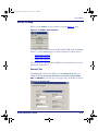
Uploading Data to the Host PC ......................................................................................3-2
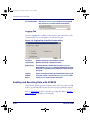
Using XFER32 .............................................................................................................3-2
XFER32 Setup ......................................................................................................3-3
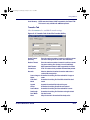
General Tab ...................................................................................................3-3
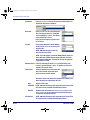
Transfer Tab ..................................................................................................3-5
Logging Tab ...................................................................................................3-6
Sending and Receiving Data with XFER32 .................................................................3-6
Transmit Files .................................................................................................3-7
Receive Files ..................................................................................................3-7
Downloading Applications with PPGXFER ........................................................................3-8
Removing Collected Data from Memory ........................................................................ 3-13
Appendix A. Falcon PT40 Batteries .................................................................. A-1
Battery Overview ........................................................................................................A-1
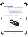
Main Battery Installation ..............................................................................................A-3
Recharging the Batteries ..............................................................................................A-4
Using the Dock Charging Slot (Battery only) .............................................................A-4
Using the PT40 Dock (PT40 Unit) ............................................................................A-5
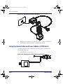
Using the Serial Cable and Power Adaptor (PT40 Unit) ...............................................A-6
Storing the Main Battery ..............................................................................................A-7
Backup Battery ...........................................................................................................A-7
Low Battery Indication .................................................................................................A-7
Main Battery ........................................................................................................A-7
Backup Battery .....................................................................................................A-8
Appendix B. PT40 Dock, Serial Cable, and Power Adaptor................................ B-1
Overview ...................................................................................................................B-1
PT40 Dock ...........................................................................................................B-1
Serial Cable .........................................................................................................B-2
Power Adaptor ......................................................................................................B-2
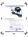
Attaching the PT40 to a PC ...........................................................................................B-3
Using the Dock to Recharge the Main Battery ..................................................................B-4
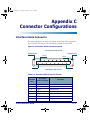
Appendix C. Connector Configurations............................................................. C-1
Interface Cable Connector ............................................................................................C-1
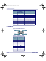
PT40 Dock .................................................................................................................C-2
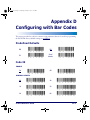
Appendix D. Configuring with Bar Codes ......................................................... D-1
Predefined Defaults .................................................................................................... D-1
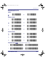
Code 39 .................................................................................................................... D-1
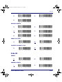
Interleaved 2 of 5 ...................................................................................................... D-3
Codabar .................................................................................................................... D-4
Code 93 .................................................................................................................... D-5
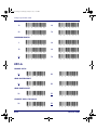
UPC-A ...................................................................................................................... D-6
UPC-E ....................................................................................................................... D-7
EAN/JAN ................................................................................................................... D-7
Product Reference Guide
iii
2340.book Page iv Wednesday, January 29, 2003 12:50 PM
Index
UPC/EAN/JAN Extensions ............................................................................................ D-8
Code 128 .................................................................................................................. D-8
Other Controls ........................................................................................................... D-9
Clock and Calendar ....................................................................................................D-12
Serial Parameters ......................................................................................................D-12
Appendix E. Programming Parameters ............................................................. E-1
Overview ...................................................................................................................E-1
Using Bar Codes ..........................................................................................................E-3
Using Predefined Defaults ......................................................................................E-3
Alternate Parameters for the Falcon PT40 .................................................................E-4
Guidelines for Creating Programming Bar Codes ........................................................E-5
Using Multiple Bar Codes ........................................................................................E-5
Programming Parameters .............................................................................................E-6
Setting the Hour Format, Time, and Date .................................................................E-6
Time .............................................................................................................E-6
Date .............................................................................................................E-6
Xmodem Protocol ..................................................................................................E-7
Save-and-Exit Settings ..........................................................................................E-7
Code 39 and ASCII Equivalents for Serial Characters .................................................E-8
General Programming Parameters .................................................................................E-9
Serial Parameters ..................................................................................................... E-12
Appendix F. Memory Table ............................................................................... F-1
Appendix G. Maintenance, Troubleshooting, and Technical Support ................. G-1
Overview .................................................................................................................. G-1
Maintaining your Falcon PT40 ....................................................................................... G-1
Troubleshooting ......................................................................................................... G-2
Technical Support ...................................................................................................... G-3
PSC Website Support ...................................................................................... G-3
Reseller Technical Support .............................................................................. G-4
PSC Website TekForum ................................................................................... G-4
Telephone Technical Support ........................................................................... G-4
Index .................................................................................................................. xi
iv
Falcon® PT40
2340.book Page v Wednesday, January 29, 2003 12:50 PM
Preface
About this Guide
How to Use This Manual
This Product Reference Guide contains comprehensive instructions on the
Falcon PT40’s software, batteries, dock, serial cable, data transfer. It also contains advanced user information such as pinouts, bar code configuration and
parameters. This section of the manual provides both a general description of
the product’s features and an overview of the manual’s contents and organization.
Manual Overview
This manual contains the following sections:
•
The Preface, About this Guide presents the manual’s contents, shows
manual style conventions, and information regarding registering your
Falcon PT40 unit.
•
lists the bar code symbologies the
scanner will read. It describes features and specifications, of the PT40,
including keypad, the display, and accessories. Read this section before
using the PT40.
•
Chapter 2, Data Collection with PT40 Software Applications on page 2-1
contains complete information about using the PALPRO40 and data
collection applications that are loaded in memory on the PT40, setting
the date, time, and password.
•
Chapter 3, Transferring Files and Data on page 3-1
Chapter 1, Introduction on page 1-1
contains information
about transfering application, and data files between the PT40 and a
Host PC. Read this section to upload collected data.
Product Reference Guide
v
2340.book Page vi Wednesday, January 29, 2003 12:50 PM
About this Guide
•
Appendix A, Falcon PT40 Batteries on page A-1,
describes installation,
charging, and disposal information on the PT40’s main battery and
backup battery.
•
Appendix B, PT40 Dock, Serial Cable, and Power Adaptor on page B-1,
describes how to set up and use the Dock or serial cable to transfer data
between the PT40 and a Host PC. Refer to this section before using the
dock for the first time or when connecting it to a PC.
•
Appendix C, Connector Configurations on page C-1,
•
Appendix D, Configuring with Bar Codes on page D-1, explains how to customize the PT40’s settings using bar codes. It contains bar codes for
scanning to set selected programming parameters. Use this section to
change settings in the PT40.
•
Appendix E, Programming Parameters on page E-1, contains ID numbers,
identifies pin assignments for the connectors on the PT40 and PT Dock. Refer to this section to order cables or make your own cables.
acceptable settings, and defaults for all programming parameters for the
PT40. Refer to this section to change settings in the PT40.
•
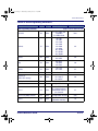
Appendix F, Memory Table on page F-1, is a table that shows the relationship between the amount of installed RAM and the number and size of
records the PT40 will hold.
•
Appendix G, Maintenance, Troubleshooting, and Technical Support on
page G-1, provides information about care and cleaning your Falcon
PT40, troubleshooting, and technical support.
Registering Your Falcon PT40
PSC values your feedback. Please take a few moments and complete the
Product Registration form located on PSC's website or on the PSC Manuals
CD. Registering your products ensures that you will be informed of the latest
product news, software updates and other future developments from PSC.
vi
Falcon® PT40
2340.book Page vii Wednesday, January 29, 2003 12:50 PM
Document Conventions
Document Conventions
Formatting conventions are used throughout this guide as a method of providing consistency for notes, cautions, and warnings.
Notes appear throughout the manual to provide additional information on a topic,
including technical details, exceptions to instructions and other pertinent information. These notes are identified by the notepad symbol.
CAUTION
Cautions indicate potential damage to data or the unit if directions on are not followed correctly. They also indicate when you should take care to use the correct
PSC accessories, parts and connectors.
Warnings indicate potential damage to the Falcon PT40, docks, and battery chargers if directions are not followed correctly.
WARNING
Keys and Keystroke Conventions
PT40 keys and keystroke conventions are used throughout this manual to
identify the difference between a key on the PT40 and keystrokes input by the
user. Brackets such as: <ENT>, indicate a key on the Falcon PT40. Data or
keystrokes entered by the user, and directories, filenames, file extensions, and
path names are printed in this monospaced typeface.
Product Reference Guide
vii
2340.book Page viii Wednesday, January 29, 2003 12:50 PM
About this Guide
PT40 Labels
These labels are for illustrative purposes only.
Figure 1. Falcon PT40 Laser Label
Figure 2. Falcon PT40 Battery Compartment Label
Figure 3. Falcon PT40 Dock Label
viii
Falcon® PT40
2340.book Page 1 Wednesday, January 29, 2003 12:50 PM
Chapter 1
Introduction
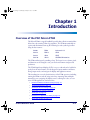
Overview of the PSC Falcon PT40
The Falcon PT40 is a rugged, handheld, portable data-collection terminal that
allows bar code scanning technology anywhere. The PT40 automatically recognizes and discriminates among the following bar code symbologies when
using the laser scanner:
Codabar
EAN-8
Interleaved 2 of 5
Code 39
EAN-13
UPC-A
Code 93
JAN-8
UPC-E
Code 128
JAN-13
UPC/EAN/JAN extensions
The PT40 verifies input by sounding a beep. The beeper’s tone, volume, pitch,
and duration can be changed to suit your work environment and personal
preferences.
The PT40’s liquid crystal display (LCD) is easy to read and can be backlit for
poorly lit work environments. Use the keypad to input numbers and letters,
change input modes, and navigate the display and application menus.
This introduction covers the basic functions of the PT40 operation, including
turning the PT40 on and off, using action keys, inputting data and alphanumeric key use, navigating the display screen, scanning bar codes, an overview of PT40 applications, and accessories.
•
PT40 Power Button and Reset starting on page 1-2.
•
The Keypad starting on page 1-3.
•
The Display Screen starting on page 1-6.
•
The PT40 Laser starting on page 1-8.
•
The Beeper on page 1-9.
•
PT40 Software Applications starting on page 1-9.
•
Accessories starting on page 1-12.
Product Reference Guide
1-1
2340.book Page 2 Wednesday, January 29, 2003 12:50 PM
Introduction
PT40 Power Button and Reset
Turning the PT40 On
Press the green <PWR> key displayed at left to turn the PT40 on. The first
screen that appears on the PT40, unless the software has been customized, is
shown below.
-Falcon PT40zVer 020.5/Z0.2
System RAM 256K
10/16/02 14:09
¤
press any key
If the unit had been running before it was turned off, the display screen
returns to the view displayed when the unit was turned off.
Auto-Off Timeout
The PT40 is programmed to shut itself off automatically if it is not used for
ten (10) minutes. This Auto-Off timeout conserves power in the PT 40 by partially shutting down when it is not in use. Press the <PWR> key to return the
PT40 to full power.
The following Auto-Off timeout values can be customized:
Auto-Off Timeout
Values
Value range
1 - 99 minutes
Default value
10 minutes
Disable value
00
Refer to Auto-Off on page E-11 for more information on customizing this feature.
Turning the PT40 Off
Turn the PT40 off by pressing the <PWR> key displayed at left. This turns the
screen display off, but does not clear any information in the PDT’s randomaccess memory (RAM). The PT40 will return to this location when it is
turned on again. There is no beep when the <PWR> key is pressed to turn the
PT40 off.
1-2
Falcon® PT40
2340.book Page 3 Wednesday, January 29, 2003 12:50 PM
The Keypad
Resetting the PT40
Sometimes you will need to reset the PT40. Both Soft Reset and Hard Reset
return the PT40 to the opening display screen (refer to Figure 1-1 on page 1-2)
and return a unique series of beeps and tones to verify the reset.
Resetting the PT40 is similar to pressing <Ctrl>+<Alt>+<Delete> on a PC. All data
stored in the portable’s memory is cleared.
CAUTION
Soft Reset: Use a soft reset to reboot a PT40 when there is power available.
Scan the following reset bar code:
Reset
*
+
.
*
Hard Reset: Use a hard reset to reboot a PT40 without power.
1. Remove the main battery or external power supply.
2. Press and hold the <CLR> and <ENT> keys while reinserting the main
battery or reconnecting the power supply.
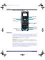
The Keypad
The keypad on the PT40 has three types of keys: action keys, function keys,
and data keys. Each key produces a beep when pressed.
•
Refer to Figure 1-2 on page 1-4 for an illustration of the Falcon PT40.
•
Refer to Table 1-1 on page 1-5 for a list of data keys and cycles.
•
Refer to Table 1-2 on page 1-5 for a list of action keys and functions.
Product Reference Guide
1-3
2340.book Page 4 Wednesday, January 29, 2003 12:50 PM
Introduction
Figure 1-1. Falcon PT40 Keypad
Function Keys
Enter Key
Clear Key
Scan Key
Data Keys
Navigation Keys
Shift Key
Backlight Key
Power Key
Data Keys
Use the twelve (12) data keys to enter letters, numbers, and other characters. If
you enter an incorrect number or character, press the <CLR> key to move the
cursor back one position. Press and hold the <CLR> key to clear an entire line.
Normal Mode. By default, data keys yield numbers.
Shift Mode. To input letters, press the <SH> key to enter Shift mode. The
Shift mode cursor is displayed with reverse video. The PT40 remains in Shift
mode until you press <SH> again.
Press the data key once, twice, or more times to cycle through the letters until
the desired letter appears on the display. After the last letter in the sequence for
that key, the next keypress yields the number. Another keypress starts the letter
sequence again. Letters are only available in upper case.
1-4
Falcon® PT40
2340.book Page 5 Wednesday, January 29, 2003 12:50 PM
The Keypad
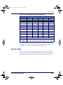
Table 1-1. Inputting Characters Using Data Keys
Normal Mode
Shift Mode
Number/Symbol
First
Keypress
Second
Keypress
Third
Keypress
Fourth
Keypress
Fifth
Keypress
0
space
0
space
0
space
1
1
1
1
1
1
2
A
B
C
2
A
3
D
E
F
3
D
4
G
H
I
4
G
5
J
K
L
5
J
6
M
N
O
6
M
7
P
Q
R
S
7
8
T
U
V
8
T
9
W
X
W
Z
9
* (Asterisk)
In both Normal and Shift mode, press the * key to insert an asterisk.
. (Decimal/
Period)
In both Normal and Shift modes, press the Decimal/Period key to
insert a decimal or period into a number sequence or character string.
There is a default one (1) second time-delay before the cursor moves to the
next position. This duration value can be customized. Use the <RIGHT> arrow
navigation key to move one position right before delay expires.
Function Keys
There are four function keys, <F1> through <F4>, at the top of the keypad.
Press the <SH> key to enter Shift mode and access function keys <F5> through
<F8>. The actions for function keys are determined by the active program.
Product Reference Guide
1-5
2340.book Page 6 Wednesday, January 29, 2003 12:50 PM
Introduction
Action Keys
Ten action keys, including the four navigation keys, are described in Table 1-1.
Table 1-2. Falcon PT40 Action Keys
Button
Function
/Mode
Description
Referred to
As
Clear
Press <CLR> to move the cursor back one position.
Press and hold <CLR> to clear an entire line of text.
<CLR>
Scan
Aim the PT40 at a bar code and press the <SCAN>
key to activate laser scanning mode.
<SCAN>
Enter
Press the <ENT> key to enter the current data string
and move to the next command.
<ENT>
Up
Arrow
Press the <UP> arrow to move the actual display up
one line in the virtual display.
<UP>
Down
Arrow
Press the <DOWN> arrow to move the actual display
down one line in the virtual display.
<DOWN>
Left
Arrow
Press the <LEFT> arrow to move the actual display
to the left 4 characters in the virtual display. I
<LEFT>
Right
Arrow
Press the <RIGHT> arrow to move the actual display
to the right 4 characters in the virtual display. In Shift
mode, the <RIGHT> arrow key acts as an insert key
to override the time delay.
<RIGHT>
Shift
Mode
Press the <SH> key to enter Shift mode. Use Shift
mode to access alpha characters or toggle the function keys between <F1>-<F4> and <F5>-<F8>.
<SH>
Power
Press the <PWR> key to turn the PT40 on and off.
When the PT40 is turned on, it beeps and returns to
the location at last shut off.
<PWR>
Press the <BL> key to turn the LCD backlight on or
Backlight
off. The default timeout on the backlight is 30 secOn/Off
onds. The duration value can be customized.
1-6
<BL>
Falcon® PT40
2340.book Page 7 Wednesday, January 29, 2003 12:50 PM
The Display Screen
The Display Screen
The default system font for the PT40 is a 5x7 (width x height in pixels) font
based on the Codepage 850 Western European character set. This size font
allows the PT40's LCD display screen to show 6 lines of text with up to 16
characters on each line when using only the default system font.
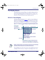
Actual vs. Virtual Display
The Falcon PT40's actual display screen is a window to a larger display area
called the virtual display (refer to Figure 1-3). Most applications you will use
will fit into the actual display. However, applications can sometimes contain
data longer than the default 6 line x 16 character view of the actual display.
Figure 1-2. Virtual vs. Actual Display Using Default System Font
0,0
Actual Display
16 characters wide
80 characters wide
The shaded box
F1=NEXT F2=PRE
represents the PT40
REC#11 OF 16
display screen.
6 lines high 120850A30NME5274J400967629
25 lines high
F3=REV F4=EXIT
F1=NEXT F2=PRE
REC#12 OF 16
120850A30NME5274J400984019
F3=REV F4=EXIT
F1=NEXT F2=PRE
REC#13 OF 16
120850A30NME5274J400942885
F3=REV F4=EXIT
Virtual Display: The larger area represents the maximum size for the Virtual Display in some applications
(visible to the user only by using the arrow navigation keys)
Adding or changing character sizes will change the appearance of the actual display.
The number of lines and characters will vary with the character sizes.
The actual display screen shows only a portion of the available data in the virtual display. Use the arrow keys to navigate the actual display screen to view
Product Reference Guide
1-7
2340.book Page 8 Wednesday, January 29, 2003 12:50 PM
Introduction
the virtual display data. The text in the virtual display remains in place and the
actual display screen changes its view within the virtual display.
If you scan longer bar codes or enter more data than can fit in a single line of
the virtual display, the data automatically wraps to the next line. Because
applications for the PT40 can contain and use different fonts, the amount of
data that is available within the virtual display will vary.
The virtual display maintains the latest lines of data once all lines of the virtual
display are full. The oldest lines of data are “pushed off the top” as new data is
added at the bottom.
Contrast
To adjust the screen contrast while the PT40 is running an application, press
the <SH> key to enter Shift Mode. Use the Up or Down arrow keys to increase
or decrease the screen contrast.
Backlight
The PT40’s liquid crystal display (LCD) is easy to read in all lighting situations using the backlight feature. Press the <BL> key to turn the backlight on
or off.
Displaying Information about the PT40
Display information about the PT40 by scrolling the actual display past the
last character on a current line. Press the <Right> arrow key until the version
number and current application name are displayed. The actual display lists
the system version number and the amount of random-access memory
installed (refer to Figure 1-1 on page 1-2).
The PT40 Laser
The PT40 laser is an integral part of the Falcon PT40. Use the PT40 to scan
bar code labels on flat, curved, or irregular surfaces at distances ranging from
one inch to 18 inches.
The actual scan distance depends upon the symbology, density, and the lighting
conditions.
1-8
Falcon® PT40
2340.book Page 9 Wednesday, January 29, 2003 12:50 PM
The Beeper
Scanning Bar Codes with the PT40
Aim and press the <SCAN> key. Figure 1-4 illustrates the correct orientation for
best scanning results.
•
The laser should be pointed at a slight angle to the bar code. Do not orient the PT40’s laser parallel or perpendicular to the bar code.
•
The laser beam must cross the entire bar code. The PT40 cannot correctly read if the entire bar code is not scanned.
Figure 1-3. How to Scan
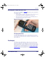
Verifying Operation
A red LED (light-emitting diode) on the top right indicates laser activation
and good reads. The PT40 verifies that it accepts the scanned input by sounding an audible tone.
The Beeper
The PT40 provides audible feedback to indicate when a bar code has been
scanned successfully and to acknowledge when a key has been pressed. The
default setting provides one beep to indicate a good scan or key entry. Another
beep sequence warns of possible problems. The tone, pitch, volume, number,
and length of beeps can all be modified. Refer to Configuring with Bar Codes
starting on page D-1 for more information on customizing your Falcon PT40.
Product Reference Guide
1-9
2340.book Page 10 Wednesday, January 29, 2003 12:50 PM
Introduction
PT40 Software Applications
The Falcon PT40 comes from the factory with PSC’s PALPRO40 application
and three other data collection applications already installed.
If your PT40 software has been customized, it may operate differently. Check with
your systems administrator for instructions.
PALPRO40
PALPRO40 is
part of the PSC Portable Applications Library (PAL). With PAL,
you can customize the PT40 without programming. PALPRO40 consists of
three programs, which coexist in memory:
ASSETPRO Use ASSETPRO for tracking assets at various locations.
INVPRO
Use INVPRO for inventory control. Customize it to collect item-and-quantity
information or item-only data.
TRACKPRO Use TRACKPRO for tracking check-in and check-out of articles at one or
more locations. An optional date-and-time stamp records when each item is
checked in or out.
A password is required when all three PALPRO40 applications are loaded at the
same time.
Data Collection Applications
In addition to PALPRO40, the PT40 also comes with the following basic data
collection applications loaded in memory:
DESCRIPT
DESCRIPT is a description application.
INVMODEM INVMODEM is an inventory application with a modem option.
TIMESTMP
TIMESTMP is an item-tracking application that records the date and time
data was entered.
No password is required for these applications.
PT Program Generator (PPG)
PT Program Generator™ v5.0 (PPG™) is an application designed to work
with the Falcon PT40 to create custom applications that collect, verify, and
1-10
Falcon® PT40
2340.book Page 11 Wednesday, January 29, 2003 12:50 PM
PT40 Software Applications
store data. Use PPG and it’s utilities to create, compile and download custom
applications to the PT40. For more information about PPG, go to the Product
Manuals link at www.pscnet.com to view the most current PPG User’s Guide.
There is no longer keyboard wedge support in PPG v5.0. Applications created in
previous versions of PPG that use the keyboard wedge option can be saved in PPG
v5.0, but they must be updated with a new input method after you save them..
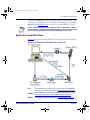
Application and Data Flow
Figure 1-5
illustrates data and application file flow between the PC and PT40.
Figure 1-4. Application and Data Flow on the PT40
PPG
PPG is designed to work with the Falcon PT40 to create custom applications
that collect, verify, and store data. Refer to PT Program Generator (PPG).
PPGXFER Use PPGXFER to download the operating system and applications. Refer to
Downloading Applications with PPGXFER starting on page 3-8.
XFER32
Product Reference Guide
Use XFER32 to transfer data files. Refer to Using XFER32 on page 3-2.
1-11
2340.book Page 12 Wednesday, January 29, 2003 12:50 PM
Introduction
Accessories
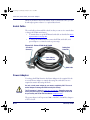
PT40 Dock, Serial Cable and Power Adaptor
The PSC Falcon PT40 Dock, Serial Cable, and Power Adaptor are specifically
designed for use with the Falcon PT40. Use the dock or serial cable for data
transmission between the portable and a PC. They can also be used to recharge
the portable’s rechargeable main Lithium-ion battery.
When the portable is connected to the dock or serial cable connected to a PC,
you can download programs or data to it, or upload data from it. For more
detailed information about the Falcon PT40 Dock and serial cable, refer to
PT40 Dock, Serial Cable, and Power Adaptor on page B-1.
PT40 Batteries
The PT40 runs on two types of batteries. The main Lithium-ion battery supplies operating power for the PT40. The internal lithium-ion battery provides
backup power to maintain the random-access memory and the real-time clock
when the main batteries are removed. The backup battery is recharged by the
main battery.
When you first remove your Falcon PT40 from the box, the main battery may require
charging.
PSC recommends that you purchase two main batteries and keep a spare battery
charging in the battery slot at all times. Then you can swap out the batteries when the
main battery runs low, rather than stopping to recharge a single battery.
Lithium-ion batteries benefit from an initial 'conditioning'. For the first 3 charge
cycles, fully charge the main battery for at least 12 to 24 hours. Then allow it to fully
discharge before recharging it again.
After a prolonged storage period the main battery may again require three to four
charge/discharge cycles to achieve maximum capacity.
Recycle Lithium-Ion Batteries.
Do not throw Lithium-Ion Batteries in the trash.
CAUTION
Always charge the battery within the temperature range of 32°–113°F (0°–45°C).
1-12
Falcon® PT40
2340.book Page 13 Wednesday, January 29, 2003 12:50 PM
Accessories
To recharge the PT40’s batteries and for more detailed information about the
main and backup batteries, refer to Falcon PT40 Batteries on page A-1 and
Using the Dock to Recharge the Main Battery on page B-4.
PT40 Belt Clip
To install the belt clip, complete the following steps:
1. Follow the instructions for Main Battery Installation starting on page A-3 to
remove the main battery and battery cover door.
Figure 1-5. Belt Clip and Knob Assembly
Release
button
Belt Clip
Slot
Belt Clip
Belt Clip Knob
2. Align the belt clip knob with the slight depression just above the battery
compartment.
• Position the knob facing out and the small clip lined up with the
small slot inside the unit. (Figure 1-6 shows the belt clip knob)
• Press up firmly on the belt clip to insert it into the slot (refer to
Figure 1-6 for the location of an installed belt clip knob).
3. Replace the battery and battery compartment cover as described in Main
Battery Installation starting on page A-3.
4. Slip the belt clip knob (refer to Figure 1-6) into the slot in the belt clip.
5. Attach the belt clip to your belt.
6. To release the unit from the belt clip, press the button at the top of the
belt clip and slip the unit up from the slot.
Product Reference Guide
1-13
2340.book Page 14 Wednesday, January 29, 2003 12:50 PM
Introduction
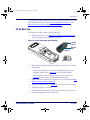
PT40 Soft Case
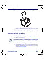
Your PT40 may also come with a soft case. If you wish to use it, open the back
and put the PT40 inside, bottom first.
Figure 1-6. Falcon PT40 Soft Case
Falcon PT40 Product CD
Contains the following applications and documents:
•
PALPRO40
•
XFER32
•
Falcon PT40 Quick Reference Guide (QRG) in PDF format.
•
Falcon PT40 Product Reference Guide (PRG) in PDF format.
(Refer to Using PALPRO40 starting on page 2-7).
(Refer to Using XFER32 starting on page 3-2).
PDF (portable document format) files of the QRG and PRG are both available
on the product CD included with your PT40. Or you can download the most
recent version of any PSC manual from the website at www.pscnet.com.
View PDF files with Adobe Acrobat Reader v4.0 or higher, which you can
download from Adobe’s website at www.adoble.com.
A printed version of the Falcon PT40 Quick Reference Guide (QRG) shipped with your
Falcon PT40. Use this document to get the Falcon PT40 up and running quickly.
1-14
Falcon® PT40
2340.book Page 1 Wednesday, January 29, 2003 12:50 PM
Chapter 2
Data Collection with PT40
Software Applications
Overview
This section of the manual describes the following data collection processes
with the PT40:
•
Quick Start starting on page 2-2.
•
Setting Up the PT40 starting on page 2-3.
•
•
•
•
•
Switching Applications starting on page 2-4
Setting the Time and Date starting on page 2-5.
Setting a Password starting on page 2-6.
Using PALPRO40 to Collect Data starting on page 2-7.
•
•
•
•
•
•
Getting Started starting on page 2-3.
Installing PALPRO40 starting on page 2-7.
Using PALPRO40 starting on page 2-7.
Using ASSETPRO starting on page 2-10.
Using INVPRO starting on page 2-12.
Using TRACKPRO starting on page 2-15.
Other Data Collection Applications starting on page 2-18.
• DESCRIPT starting on page 2-18.
• INVMODEM starting on page 2-23.
• TIMESTMP starting on page 2-25.
•
Reviewing the Collected Data starting on page 2-27.
PALPRO40 and the other data collection applications are loaded in the PT40’s
memory when it arrives from the factory, unless it is customized.
Product Reference Guide
2-1
2340.book Page 2 Wednesday, January 29, 2003 12:50 PM
Data Collection with PT40 Software Applications
If you want to work with PPG, please refer to the PPG User’s Guide, included
on the CD that came with your PT40.
Quick Start
The Falcon PT40 comes with an application named PALPRO40 loaded in
memory. PALPRO40 includes three useful data-collection programs for using
the PT40 without additional programming.
Follow the steps below to begin using the PT40 with PALPRO40 immediately.
Page references show where to find more information.
1. Fill out and return the registration card enclosed with the unit.
2. Turn the PT40 on by pressing the <PWR> key. Refer to Turning the PT40
On on page 1-2 for additional information about starting the PT40.
If the PT40 does not turn on when the <PWR> key is pressed, you many need to
recharge the main battery (refer to Falcon PT40 Batteries starting on page A-1).
If the PT40’s software has been customized, it may operate differently. Check with
a systems administrator for instructions.
3. Press the <ENT> key twice to accept the displayed date and time. If necessary, change the date and time settings. (Refer to Setting the Time and
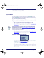
Date on page 2-5.)
Figure 2-1. The Application/Test menu
APPLICATION/TEST
F1=PALPRO40
F2=DESCRIPT
F3=INVMODEM
F4=TIMESTP
F5=UTILITIES
4. Once the unit has been initialized, the display will show the APPLICATION/TEST menu in Figure 2-1 on page 2-2, above.
• Press <F1> to begin using PALPRO40.
5. The application requests an update to the date and time again. You can
change them here if necessary. Or, press <ENT> twice to skip either the
date or the time.
2-2
Falcon® PT40
2340.book Page 3 Wednesday, January 29, 2003 12:50 PM
Setting Up the PT40
6. Enter a password. (Refer to Setting a Password on page 2-6.)
7. Press any function key to continue on to the PALPRO40 Options menu.
8. Press the <F2> key to display the list of available applications. Select the
application to use. (Refer to Switching to Another PALPRO40 Application
on page 2-9.)
The PT40 is now ready to begin collecting data. For information about
sending collected data from the PT40 to a PC, refer to Uploading Data to the
Host PC starting on page 3-2.
Setting Up the PT40
You can collect data records on the PT40, and send the records later to a host
PC. The number of data records that can be collected before being uploaded
depends on how much random-access memory (RAM) is installed in the
PT40.
The PT40 stores data records in files in random-access memory (RAM). The
number of records that can be collected depends upon the amount of RAM
available to the application. Refer to the Memory Table on page F-1 to determine the amount of RAM you need.
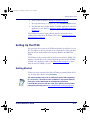
Getting Started
Unless it has been customized, the Falcon PT40 is programmed from the factory for basic data collection using PALPRO40.
This chapter describes how to use the PT40 with its original PSC programming
(i.e. PALPRO40). If the PT40 has been customized, it may operate differently.
Check with a systems administrator for revised operating instructions.
If the PT40 does not turn on when the <PWR> key is pressed, you many need to
recharge the main battery (refer to Falcon PT40 Batteries starting on page A-1).
Product Reference Guide
2-3
2340.book Page 4 Wednesday, January 29, 2003 12:50 PM
Data Collection with PT40 Software Applications
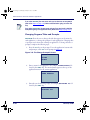
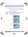
Switching Applications
The PT40 can have as many as 4 different applications in memory, any one of
which can be selected and run. To move to a different application from the
application currently running, you must initiate a special key-sequence on the
keypad. Simultaneously press the <SH>+<CLR>+<ENT> keys to put the currently running application on hold. A special dialog display opens
You selected the
termination of
the application!
F1= Terminate
F2= Upload files
F4= Continue app
Terminating the Application <F1>
1. Press the <F1> key to terminate execution of the current application.
The PT40 returns to the opening sign-on screen.
If you select terminate the application at this screen, you will permanently destroy
any data you collected while the application was running.
CAUTION
2. Press any key to enter the APPLICATION/TEST menu and can then select
another application to run.
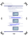
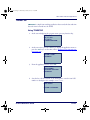
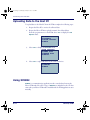
Uploading Files <F2>
1. Press the <F2> key to upload any data that has been collected while running the application.
2. A new display appears, with instructions for uploading the data from the
application.
Prepare host to
rcv files, and
connect I/O to
host I/O port.
To save the data
press any key
3. Press any key to initate the data upload. (This is similar to transferring
data files using XFER32; refer to Using XFER32 starting on page 3-2.)
2-4
Falcon® PT40
2340.book Page 5 Wednesday, January 29, 2003 12:50 PM
Setting Up the PT40
Continuing the Application <F4>
Press the <F4> key to return to the current application and continue collecting
data with the application.
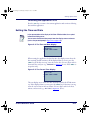
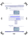
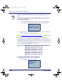
Setting the Time and Date
In the representations of the display of the Falcon PT40 that follow, the ¤ symbol
indicates the blinking cursor.
You can access the date and time prompts from other display screens and menus
(such as the password prompt in Figure 2-4 on page 2-6).).
Figure 2-2. The Time and Date Display
Current Date:
09/23/02
Enter New Date:
¤
When starting the application for the first time, the display screen shows the
date currently loaded in memory. If the displayed date is correct, press the
<ENT> key. If the date is wrong, enter the correct date. Use two digits each for
the month, day, and year (e.g., 092302 for Figure 2-2, above). Press <ENT> to
accept the entry.
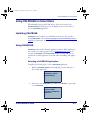
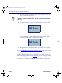
Figure 2-3. The Current Time Display
Current Time:
21:17:32
Enter New Time:
¤
The next display screen shows the time currently loaded in the PT40’s memory. If the displayed time is correct, press the <ENT> key. If the time is wrong,
enter the correct time in 24-hour format. Use two digits each for the hour,
minute, and seconds (e.g., 211732 for Figure 2-3, above).
Product Reference Guide
2-5
2340.book Page 6 Wednesday, January 29, 2003 12:50 PM
Data Collection with PT40 Software Applications
Setting a Password
A password is required when you install the entire suite of PALPRO40 applications. Password security allows a manager or supervisor to customize the
PALPRO40 software and then hand it off to a worker. A password can contain
up to 128 characters and can use any characters available on the PT40.
Figure 2-4. The Password Display
ENTER CURRENT
OR NEW PASSWORD
¤
F-KEY=SET TIME
Without the password, the worker cannot switch applications or make changes
to an application’s title or prompts. The password prompt screen appears after
entering the date and time from the application’s initial startup.
If you lose or forget your password, you must reset the PT40 and start over with a
new password.
CAUTION
After you enter your password, the text in Figure 2-5 is displayed.
Figure 2-5. The PALPRO40 Opening Display
PSC PALPRO40
08:18:04¤
10/16/02
F-KEY=CONTINUE
Press any function key to bring up the PALPRO40 Options menu. The PT40 is
now ready to collect data.
2-6
Falcon® PT40
2340.book Page 7 Wednesday, January 29, 2003 12:50 PM
Using PALPRO40 to Collect Data
Using PALPRO40 to Collect Data
When finished setting up the PT40 (refer to the previous section), the
PALPRO40 Options menu appears on the display screen. Use the menu to
choose a PALPRO40 application.
Installing PALPRO40
PALPRO40 comes installed on your PT40 from the factory. If you need to
reinstall PALPRO40, refer to Downloading Applications with PPGXFER starting on
page 3-8 for instructions on this process.
Using PALPRO40
PALPRO40 combines
three Portable Applications Library (PAL) applications
into a single, convenient program (refer to PALPRO40 on page 1-10 for an
overview of PALPRO40). With PALPRO40 installed on the PT40, you can
switch from one PAL application to another without installing each application.
Selecting a PALPRO40 Application
Complete the following steps to select a PALPRO40 application:
1. With the PALPRO40 Options menu displayed, press the <F2> key to
select a PAL application.
PALPRO40 OPTIONS
F2=SELECT PROG
F4=PASSWORD
¤
2. Press <F1> to use ASSETPRO, press <F2> to use INVPRO, or press <F3>
to use TRACKPRO.
F1=ASSET MGMT
F2=INV MGMT
F3=ITEM TRACKING
F4=EXIT¤
Product Reference Guide
2-7
2340.book Page 8 Wednesday, January 29, 2003 12:50 PM
Data Collection with PT40 Software Applications
If you select INVPRO), the next screen asks you to select one or two prompts
(refer to the Steps on page 2-12). Make a selection before going on to the next
step.
If you select TRACKPRO, the next screen asks you if you want to add a date/time
stamp before getting to the application menu. (Refer to the Steps on page 2-15.)
Changing Program Titles and Prompts
PALPRO40 allows the user to change the title that appears on the menu for
each application, or change the prompts for each application. Changing titles
or prompts can be done after selecting an application. To change the title or
prompts, complete the following steps:
1. Press the <F3> key at the prompt. To use the application’s current title
and prompts, select <F4> at the prompt in Figure 2-6.
Figure 2-6. The Change Prompts? Screen
CHANGE PROMPTS?
F3=YES
F4=NO¤
2. Enter a name for the application (for example, FIXED ASSETS) followed by the <ENT> key. The entered name appears at the top of the
application menu for the current application.
ENTER APPL TITLE
FIXED ASSETS¤
3. Enter the text for the first prompt (for example, BUILDING ID) followed by the <ENT> key.
ENTER PROMPT 1
BUILDING ID¤
2-8
Falcon® PT40
2340.book Page 9 Wednesday, January 29, 2003 12:50 PM
Using PALPRO40 to Collect Data
4. Enter the text for the second prompt (for example, ASSET NO.) followed by the <ENT> key.
ENTER PROMPT 2
ASSET NO.¤
Switching to Another PALPRO40 Application
To switch from one PALPRO40 application to another, complete the following
steps:
1. Select <F5> from the current application’s menu to exit the application.
ASSET MGMT¤
F2=COLLECT
F3=FILE OPTIONS
F5=EXIT
Enter <F5> on the keypad by pressing the <Shift> key and then the <F1> key.
2. At the prompt, enter the current password, or press any function key
(the blue keys at the top of the keypad) to return to the menu for the
current application.
ENTER PASSWORD
¤
F-KEY=EXIT
3. When the correct password is entered, the first PALPRO40 screen opens.
4. Press any function key to display the PALPRO40 Options menu.
5. Follow the Steps on page 2-7.
Product Reference Guide
2-9
2340.book Page 10 Wednesday, January 29, 2003 12:50 PM
Data Collection with PT40 Software Applications
Using ASSETPRO
Use ASSETPRO to track assets (such as furniture, phones, computers, and
electronic equipment) at various locations (e.g., departments, rooms, floors,
buildings). With ASSETPRO, enter an identification code for a location, collect all the asset IDs at the location, and then enter an identification code for a
different location.
To use ASSETPRO, complete the following steps:
1. From the ASSETPRO application menu, select <F2>.
ASSET MGMT¤
F2=COLLECT
F3=FILE OPTIONS
F4=EXIT
2. The first prompt appears on the screen. Enter the identification code for
the location (example, WH3E).
• Scan a bar code for the location or use the keypad to enter the location ID.
LOCATION ID
¤
F3=REV F4=EXIT
The code is entered automatically when using a scanner; when using a keypad,
press the <ENT> key.
3. The second prompt now appears on the first line of the screen, and the
location ID appears on the third line.
• Scan the bar code identifying an asset, or use the keypad to enter the
asset’s ID number or description (for example, 004322).
ITEM ID
¤
WH3E
F3=REV F4=EXIT
2-10
Falcon® PT40
2340.book Page 11 Wednesday, January 29, 2003 12:50 PM
Using PALPRO40 to Collect Data
4. The location ID and item ID appear together on the third line of the
screen, separated by a comma, and the second prompt remains on the
screen.
• The PT40 is ready to accept another ID for an asset at the current
location.
ITEM ID
¤
WH3E, 004322
F3=REV F4=EXIT
5. When finished collecting asset IDs for the location, press the <F4> key
to return to the first prompt.
6. Repeat steps 2 through 5, above, until IDs for each asset at every location is collected.
7. Press the <F4> key to return to the first prompt.
8. Press the <F4> key again to return to the application menu.
Refer to Uploading Data to the Host PC starting on page 3-2 to upload your data.
The PT40 stores the collected data in a single ASCII text file. When uploading
the file to the PC, the data appears as a list. Each line in the list contains two
fields separated by a comma. The first field is the location, and the second field
is the item’s identification number. The example in Figure 2-7 is part of a data
file uploaded from a PT40 that used ASSETPRO to collect data.
Figure 2-7. ASSETPRO Collected Data in ASCII text file
BLDG1,000295
BLDG1,001862
BLDG1,000945
BLDG1,001008
BLDG1,000036
BLDG1,000490
BLDG2,000288
BLDG2,002596
Product Reference Guide
2-11
2340.book Page 12 Wednesday, January 29, 2003 12:50 PM
Data Collection with PT40 Software Applications
Using INVPRO
Use this application to track inventory. INVPRO provides a choice of one
prompt or two. For example, use one prompt to scan or enter an ID number
or description for each item. Two prompts would be used to scan or enter an
item ID and the quantity of that item.
To use INVPRO, complete the following steps:
1. At the first screen that appears, press the <F4> key to use the application
with only one prompt, or use the <F3> key for two prompts.
USE 2 PROMPTS?
F3=YES
F4=NO¤
2. Press the <F3> key to change the title or prompts that appear on the
application’s display screens.
• Refer to Changing Program Titles and Prompts on page 2-8 for instructions.
• Otherwise, press the <F4> key to use the current title and prompts.
CHANGE PROMPTS?
F3=YES
F4=NO¤
3. The application menu appears next on the display screen.
4. Continue with the instructions for Using One Prompt below, or continue
with Using Two Prompts on page 2-13.
Using One Prompt
1. Select <F2> from the application menu. A prompt appears on the screen.
INV MGMT
F2=
F3=
F4=¤
2-12
Falcon® PT40
2340.book Page 13 Wednesday, January 29, 2003 12:50 PM
Using PALPRO40 to Collect Data
2. Scan the bar code for an inventory item, or use the keypad to enter the
item’s ID number or description.
Using a scanner, the code is entered automatically; with a keypad, press the
<ENT> key.
3. The item ID number appears on the third line of the screen. The PT40
is ready to accept another item ID.
ITEM ID
¤
40-000-00
F3=REV F4=EXIT
4. Repeat step 2until all IDs for all items are collected.
5. Press the <F4> key to return to the application menu.
Refer to Uploading Data to the Host PC starting on page 3-2 to upload your data.
The PT40 stores the collected data in a single ASCII text file. When uploading
the file to the PC, the data appears as a list. Each line in the list contains the
ID for a single item. The example in Figure 2-8 on page 2-13 is part of a data
file uploaded from a PT40 that used INVPRO with one prompt to collect data.
Figure 2-8. INVPRO Collected Data in ASCII text file
R44-2173
R44-2260
R44-2278
R44-2283
R44-2285
R44-2287
R44-2289
R44-2314
Using Two Prompts
1. Select <F2> from the application menu. The first prompt appears on the
screen.
ITEM ID
¤
F3=REV F4=EXIT
Product Reference Guide
2-13
2340.book Page 14 Wednesday, January 29, 2003 12:50 PM
Data Collection with PT40 Software Applications
2. Scan the bar code for an inventory item, or use the keypad to enter the
item’s ID number or description.
The code is entered automatically with a scanner; with a keypad, press the
<ENT> key.
3. The second prompt now appears on the first line of the screen, and the
item ID appears on the third line.
QUANTITY
¤
40-000-00
F3=REV F4=EXIT
4. Enter the number of individual units of the item in inventory.
5. The item number and quantity appear together on the third line of the
screen, separated by a comma, and the first prompt reappears on the
screen. The PT40 is ready to accept another item ID.
ITEM ID
¤
40-000-00, 25
F3=REV F4=EXIT
6. When finished collecting inventory data, press the <F4> key to return to
the application menu.
Refer to Uploading Data to the Host PC starting on page 3-2 to upload your data.
The PT40 stores the collected data in a single ASCII text file. When uploading
the file to the PC, the data appears as a list. Each line in the list contains two
fields separated by a comma. The first field is the item ID, and the second field
is the number of units of that item. Figure 2-9 shows part of a data file
uploaded from a PT40 that used INVPRO with two prompts to collect data.
2-14
Falcon® PT40
2340.book Page 15 Wednesday, January 29, 2003 12:50 PM
Using PALPRO40 to Collect Data
Figure 2-9. INVPRO Collected Data in ASCII text file
R44-2173,
R44-2260,
R44-2278,
R44-2283,
R44-2285,
R44-2287,
R44-2289,
R44-2314,
25
12
56
30
47
16
4
85
Using TRACKPRO
Use this application to record check-in and check-out of articles (e.g., supplies,
books, files, tools, equipment) at one or more locations. TRACKPRO uses two
prompts, one for location and one for item, looping at the second prompt
until the user exits to record a new location ID. An optional date/time stamp
records exactly when each item is taken or returned.
To use TRACKPRO, complete the following steps:
1. At the first screen, press the <F3> key to change the title or prompts that
appears on the application’s display screens.
• Refer to Changing Program Titles and Prompts on page 2-8).
• To use the current title and prompts, press the <F4> key.
CHANGE PROMPTS?
F3=YES
F4=NO¤
The following displays assume the default prompts.
2. At the next prompt, select <F3> to use the date/time stamp. Otherwise,
select <F4>.
ADD DATE/TIME
STAMP?
F3=YES
F4=NO¤
Product Reference Guide
2-15
2340.book Page 16 Wednesday, January 29, 2003 12:50 PM
Data Collection with PT40 Software Applications
3. From the application menu, select <F2>.
ITEM TRACKING¤
F2=COLLECT
F3=FILE OPTIONS
F5=EXIT
4. Press the <F1> key to record an item being checked in. Press <F2> to
record an item being checked out.
F1=CHECK IN
F2=CHECK OUT
F4=EXIT¤
5. Enter the code or name for the location by scanning a bar code or using
the keypad (e.g. MAIN).
LOCATION ID
¤
IN :
F3=REV F4=EXIT
The code is entered automatically with a scanner; with a keypad, press the <ENT>
key.
6. The ITEM ID prompt appears on the first line of the screen, and the
location ID appears on the third line.
7. Scan the bar code for the item, or use the keypad to enter the item’s ID
number or description (for example, P203).
ITEM ID
¤
IN :
F3=REV F4=EXIT
8. The location ID and item ID appear on the third line of the screen, separated by a comma. The prompt for the ITEM ID remains on the
2-16
Falcon® PT40
2340.book Page 17 Wednesday, January 29, 2003 12:50 PM
Using PALPRO40 to Collect Data
screen, and the PT40 is ready to accept another ID for an item at the
current location.
ITEM ID
¤
IN :MAIN,P203
F3=REV F4=EXIT
If the application is set up to add a date/time stamp, the date and time that the item
was checked out will follow the item ID on the third line. (You must scroll the
display to see the entire line.)
9. When finished collecting ITEM IDs for the location, press the <F4> key
to return to the prompt for the LOCATION ID.
10. Repeat steps 5 through 10 until all the IDs for the ITEMs at every location are collected.
11. Press the <F4> key again to return to the menu shown at step 4.
12. To change from check-in to check-out (or vice versa), repeat step 4.
• Otherwise, press the <F4> key to return to the application menu.
Refer to Uploading Data to the Host PC starting on page 3-2 to upload your data.
The PT40 stores check-in data in one ASCII text file and check-out data in
another file. When uploading one of the files to the PC, the data appears as a
list. Each line in the list contains two fields separated by a comma. The first
field is the LOCATION ID, and the second field is the ITEM ID.
When using the date/time stamp, each line also includes the check-in or
check-out date and time. The list shown in Figure 2-10 is part of a check-out
file uploaded from a PT40 that used TRACKPRO with the date/time stamp.
Figure 2-10. TRACKPRO Collected Data in ASCII text file
MAIN,R44-2173,10/16/02,10:27:18
MAIN,R44-2260,10/16/02,10:27:45
MAIN,R44-2278,10/16/028,11:04:51
MAIN,R44-2283,10/16/028,11:22:02
WHS,R44-2285,10/16/028,11:40:53
WHS,R44-2287,10/16/028,11:40:57
WHS,R44-2289,10/16/028,11:41:11
WHS,R44-2314,10/16/02,11:41:15
Product Reference Guide
2-17
2340.book Page 18 Wednesday, January 29, 2003 12:50 PM
Data Collection with PT40 Software Applications
Other Data Collection Applications
This section describes some other applications that are provided along with
PALPRO40. They can be loaded onto the PT40 using PPGXFER. (Refer to
Downloading Applications with PPGXFER starting on page 3-8.
DESCRIPT
The DESCRIPT application is another useful program for tracking inventory.
You can use this application with item and description files that you create and
load in advance. You can also add to files or create them from scratch in the
PT40 as you collect inventory data.
When you enter an item ID into the PT40, the DESCRIPT application checks
the loaded item file for that entry. If the ID matches one in the file, the PT40
displays a description of the item (which it gets from the loaded description
file) and prompts you for the number of individual units of the item. If the ID
does not match one in the item file, the application allows you to add the ID
and a description to the database.
The item and description files are simple ASCII text files consisting of single
lines of data. The lines in the two files correspond to each other; that is, the
first line in the description file is the description of the item in the first line of
the item file, the second line in the description file is the description of the
item in the second line of the item file, and so on.
Examples of the two types of files are shown below. The item file is on the left,
and the description file is on the right.
Figure 2-11. Item and Description ASCII Files
R44-2314
R44-2278
R44-2247
R44-2342
R44-2343
R44-2340
R44-2341
R44-2260
2-18
Falcon PDT User’s Guide
Falcon Adv User’s Guide
Falcon Developer’s Toolkit
PT Program Generator User’s Guide v5.0
PPG Quick Start Guide v5.0
Falcon PT40 Product Reference Guide
Falcon PT40 Quick Reference Guide
UPG User’s Guide, v 3.0
Falcon® PT40
2340.book Page 19 Wednesday, January 29, 2003 12:50 PM
Other Data Collection Applications
The two files must have the same number of lines, even if some of the description
lines are blank.
Refer to PT40 Serial Configuration and Connection on page C-1 for instructions
on connecting the PT40 to a PC.
You can access the date and time prompts from other display screens and menus
(such as the password prompt in Figure 2-4 on page 2-6).).
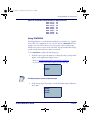
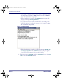
Loading Item and Description Files into the PT40
1. At the screen displaying the program name, press any function key to
display the application menu.
PSC DESCRIPT
08:17:32¤
10/16/02
F-KEY=CONTINUE
2. From the application menu, select <F2>.
F1=COLLECT
F2=RECEIVE LISTS
F3=FILE OPTIONS
F4=EXIT¤
3. If item and description lists are already loaded in the PT40, the screen
shown below is displayed. To replace a list, select <F2> and go to step 4.
To add new items to an existing list, select <F3> and go to step 7.
FILE NOT EMPTY
F2=ERASE
F3=APPEND
F4=EXIT¤
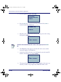
4. To erase the item and description lists that are currently loaded in the
PT40, select <F2>. The second line of the display screen will become
blank, and the lists will be removed from the PT40's memory.
Product Reference Guide
2-19
2340.book Page 20 Wednesday, January 29, 2003 12:50 PM
Data Collection with PT40 Software Applications
ERASE
F2=PICKLIST
F3=COLLECT
F4=EXIT¤
5. Press the <F4> key to return to the application menu, and select <F2> to
display the Receive Lists menu.
6. From the Receive Lists menu, select <F2> to download the item list or
<F3> to download the description list.
RECEIVE LISTS
F2=RECEIVE ITEM
F3=RECEIVE DESC
F4=EXIT¤
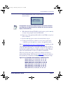
7. The next screen will prompt you to connect the PT40 to the computer.
When you are sure the PT40 is connected properly, run the appropriate
transfer program to download the list. (Use XFER32 with Windows).
Then select <F3> on the PT40 to transfer the file.
CONNECT FOR REC
ITEM LIST
F3=CONTINUE
F4=EXIT¤
8. When the transfer is completed, the PT40's screen will report on the
number of records in the list in memory. Press the <F4> key to return to
the Receive Lists menu.
RESULTS
RECORDS=16¤
F4=CONTINUE
9. To load another file, repeat steps 6 through 8. When both files are
loaded, press the <F4> key to return to the Receive Lists menu.
10. Press <F4> again to return to the Applicaiton menu.
2-20
Falcon® PT40
2340.book Page 21 Wednesday, January 29, 2003 12:50 PM
Other Data Collection Applications
To set a new date or time, refer to Setting the Time and Date on page 2-5.
Using DESCRIPT
1. From the application menu, select <F1>.
F1=COLLECT
F2=RECEIVE LISTS
F3=FILE OPTIONS
F4=EXIT¤
2. The screen prompts you for an item identification. Scan the bar code for
an item, or use the keypad to enter the item's ID number or description.
ITEM ID
R44-2342¤
F3=REV F4=EXIT¤
The code is entered automatically with a scanner; with a keypad, press the <ENT>
key.
3. If the item ID matches an ID in the item file, the PT40 displays the text
from the corresponding line in the description file and prompts you for
the number of units of the item.
QUANTITY
¤
PPG USER’S GUIDE
F3=REV F4=EXIT¤
• If there is no match for an item ID, the PT40 prompts you to reenter
the item ID or add it to the item list. To add an item to the list, press
the <F3> key.
NO MATCH RESCAN
¤
F3=CREATE
F4=EXIT
Product Reference Guide
2-21
2340.book Page 22 Wednesday, January 29, 2003 12:50 PM
Data Collection with PT40 Software Applications
• The application adds the item ID to the item list and prompts you for
a description of the item. Use the keypad to enter a description (e.g.
UPG USER’S GUIDE).
ENTER DESCRIPT
¤
• The application adds the description to the description file and
prompts you for the number of units of the item.
QUANTITY
¤
UPG USER’S GUIDE
F3=REV F4=EXIT
4. When you enter a number (e.g. 50), the PT40 returns to the first
prompt, ready to accept another item ID
5. When you are done collecting inventory data, press the <F4> key to
return to the application menu.
Refer to Uploading Data to the Host PC starting on page 3-2 to upload your data.
The PT40 stores the collected data in a single ASCII text file. When you
upload the file to your computer, the data appears as a list. Each line in the list
contains two fields separated by a comma. The first field is the item ID, and
the second field is the number of units of that item. Figure 2-12 on page 2-22.
contains part of a data file uploaded from a PT40 that used DESCRIPT to collect data.
Figure 2-12. DSCRIPT Item ID and Number of Units ASCII File
R44-2173,46
R44-2278,159
R44-2283,244
R44-2285,90
R44-2287,135
R44-2289,19
R44-2314,72
2-22
Falcon® PT40
2340.book Page 23 Wednesday, January 29, 2003 12:50 PM
Other Data Collection Applications
INVMODEM
The INVMODEM application works like INVPRO and contains an additional
feature that lets you send the collected data to a computer over a modem.
To use this application, you should have experience with modem communications. You should know how to set up the modem for your system and how to
use the communications software that runs it.
Using the Modem Feature
The modem should be set up for transmission at either 2400 or 9600 baud
with No parity, 8 data bits, 1 stop bit, and no data compression.
INVMODEM uses Xmodem protocol for file transmissions.
1. From the application menu, select <F3> for File Options.
INV W/MODEM
F2=COLLECT
F3-FILE OPTIONS
F4=EXIT¤
2. From the File Options menu, select <F2>.
*FILE OPTIONS*
F2=SEND FILE
F3=ERASE FILE
F4=EXIT¤
3. Use a cable supplied by your PSC dealer to connect the PT40 to your
modem, and select <F3> from the Send File menu.
*SEND FILE*
F2=SERIAL
F3=MODEM
F4=EXIT¤
4. Select <F2> to transmit the file at 2400 baud or <F3> to transmit it at
9600 baud.
Product Reference Guide
2-23
2340.book Page 24 Wednesday, January 29, 2003 12:50 PM
Data Collection with PT40 Software Applications
SELECT BAUD RATE
F2=2400,N,8,1
F3=9600,N,8,1
F4=EXIT¤
5. Enter the telephone number to dial. Be sure to use the format that your
modem requires. (For example, you may need to use “9,” as a prefix for
the number). When you press the <ENT> key on the keypad, the application connects to the modem and calls the number.
NUMBER TO DIAL
¤
F4=EXIT
6. When the modem connects to the remote computer, two-way communications between the PT40 and the computer is established. Use the
PT40 to enter the commands you need to prepare the computer to
receive a file.
7. When the computer is ready, press the <F3> key on the PT40 to begin
the file transmission.
¤
F3=UPLD F4=EXIT
8. When the transmission is completed, the application displays a message.
Select <F4> to return to the previous screen.
UPLOAD COMPLETE
F4=EXIT¤
9. Select <F4> to hang up the modem and return to the application menu.
2-24
Falcon® PT40
2340.book Page 25 Wednesday, January 29, 2003 12:50 PM
Other Data Collection Applications
TIMESTMP
TIMESTMP is a simple item-tracking application that records the date and time
that each item is entered into the PT40.
Using TIMESTMP
1. At the screen displaying the program name, press any function key.
TIMESTMP
08:17:32¤
10/16/02
F-KEY=CONTINUE
2. At the next screen, press the <F1> key to display the application menu or
press the <F2> key to set the time (refer to Setting the Time and Date starting on page 2-5).
F1=TIME STAMP
F2=SET TIME
F4=EXIT¤
3. From the application menu, select <F2>.
TIME STAMP
F2=COLLECT
F3=FILE OPTIONS
F4=EXIT¤
4. Scan the bar code for an item, or use the keypad to enter the item's ID
number or description (for example, R44-2342).
ITEM ID
R44-2342¤
F3=REV F4=EXIT¤
Product Reference Guide
2-25
2340.book Page 26 Wednesday, January 29, 2003 12:50 PM
Data Collection with PT40 Software Applications
The code is entered automatically with a scanner; with a keypad, press the <ENT>
key.
Use the arrow navigation keys to scroll the display window to the right to see all
the date and time information.
• The item ID appears on the third line of the screen, followed by the
date and time, and the PT40 is ready to accept another item ID.
ITEM ID
¤
R44-2342, 10/16/
F3=REV F4=EXIT¤
5. Repeat step 4 until you have collected IDs for all items. Then press the
<F4> key to return to the application menu.
Refer to Uploading Data to the Host PC starting on page 3-2 to upload your data.
The PT40 stores the collected data in a single ASCII text file. When you
upload the file to your computer, the data will appear as a list. Each line in the
list will contain the ID for a single item, followed by the date and time that the
item ID was entered in the PT40. The list below is part of a data file uploaded
from a PT40 that used TIMESTMP to collect data.
Figure 2-13. TIMESTMP Item ID and Number of Units ASCII File
R44-2314,10/16/02,10:27:18
R44-2278,10/16/02,10:27:45
R44-2247,10/16/02,11:04:51
R44-2342,10/16/02,11:22:02
R44-2343,10/16/02,11:40:53
R44-2340,10/16/02,11:40:57
R44-2341,10/16/02,11:41:11
R44-2260,10/16/02,11:41:15
Changing the Date and Time Setting
1. From the application menu, select <F2>.
F1=TIME STAMP
F2=SET TIME
F4=EXIT¤
2-26
Falcon® PT40
2340.book Page 27 Wednesday, January 29, 2003 12:50 PM
Reviewing the Collected Data
2. If the displayed date is correct, press the <ENTER> key. If the date is
wrong, enter the correct date. Use two digits each for the month, for the
day, and for the year (e.g. 101602). The program will automatically
format the entry (e.g. 10/16/02).
Current Date:
10/16/02
Enter New Date:
¤
3. If the displayed time is correct, press the <ENT> key. If the time is wrong,
enter the correct time in 24-hour format. Use two digits each for the
hour, minute, and seconds (e.g., 211732).
Current Time:
21:17:32
Enter New Time:
¤
Reviewing the Collected Data
Before uploading collected data, review it on the PT40 and delete incorrect or
unnecessary records.
1. From any screen that offers REV as an option, select <F3> to display the
data-review screen (shown in Figure 2-14 on page 2-28).
ITEM ID
¤
F3=REV F4=EXIT
• The last data that was input is displayed on the third line of the
screen.
• If the record includes a quantity, the quantity is given after a comma
at the end of the line.
Product Reference Guide
2-27
2340.book Page 28 Wednesday, January 29, 2003 12:50 PM
Data Collection with PT40 Software Applications
• The second line of the data-review screen tells the number of the currently displayed record and the total number of records. The top line
of the data-review screen offers options for moving through the
records in memory.
Figure 2-14. Data Review Displays
F1=PREV F2=NEXT
REC#65 OF 65¤
R44-2342
F3=DEL F4=EXIT¤
F1=PREV F2=NEXT
REC#65 OF 65¤
R44-2342, 15
F3=DEL F4=EXIT¤
Item-only data
Item-and-quantity data
2. Press the <F2> key to move to the next record.
• If the currently displayed record is the last one, the PT40 will briefly
display END OF FILE on the second line.
3. Press the <F1> key to move to the previous record.
• If the currently displayed record is the first one, the PT40 will briefly
display START OF FILE on the second line.
4. The 4th line of the screen offers options for deleting records and returning to the data-collection screen.
• To delete the currently displayed record, press the <F3> key. The message ARE YOU SURE? appears on the first line of the screen.
• To delete the record, press <F3> again; to cancel, press <F4>.
5. When finished reviewing the data records, press <F4> once to return to
the data-collection screen or twice to return to the application menu.
2-28
Falcon® PT40
2340.book Page 1 Wednesday, January 29, 2003 12:50 PM
Chapter 3
Transferring Files and Data
Overview
When you are finished inputting data by scanning bar codes or collecting data
in a file, transmit (upload) the files from the PT40 to the host PC using
XFER32. XFER32 is a data transfer application that is included on the CD that
came with your Falcon PT40. Refer to Using XFER32 on page 3-2.
XFER32 runs on Microsoft Windows versions ‘98, 2000, Me, NT, and XP.
Utilities are available on the CD that cam e with your PT40 and updates are free
from PSC’s website. Click on the Support link at www.pscnet.com to download
the most current file transfer program.
You can also download PDTFER from PSC’s website if you use a DOS Host PC.
PDTFER is a DOS file transfer program that runs on a DOS Host PC by issuing
commands on the DOS command line.
Refer to PT40 Dock, Serial Cable, and Power Adaptor on page B-1 for detailed
information on how to connect the PT40 to a PC.
Use only the Falcon PT40 Dock or PT40 serial cable for data transfer. The use of
another dock or serial cable could void your warranty. For a list of PT40 accessories
and part numbers, refer to PSC’s Price Book at: http: www.pscnet.com.
The following topics are covered in this section of this manual:
•
Uploading Data to the Host PC starting on page 3-2.
•
Using XFER32 starting on page 3-2.
• XFER32 Setup starting on page 3-3.
• Sending and Receiving Data with XFER32 starting on page 3-6
•
Downloading Applications with PPGXFER starting on page 3-8
•
Removing Collected Data from Memory starting on page 3-13.
Product Reference Guide
3-1
2340.book Page 2 Wednesday, January 29, 2003 12:50 PM
Transferring Files and Data
Uploading Data to the Host PC
To upload data to the Host PC from the PT40, complete the following steps:
1. Prepare the Host PC to receive the collected data.
2. Prepare the Falcon PT40 to upload (transmit) the collected data.
From the program menu on the PT40; select <F3> to display the File
Options menu.
INV MGMT¤
F2=COLLECT
F3=FILE OPTIONS
F4=EXIT
3. Select <F2> to display the Send File menu.
*FILE OPTIONS*
F2=SEND FILE
F3=ERASE FILE
F4=EXIT¤
4. Select <F2> to upload the data via the serial connection.
*SEND FILE*
F2=SERIAL
F4=EXIT
¤
Using XFER32
XFER32 is a communications application used to transfer data between the
Falcon PT40 and a Host PC A copy of XFER32 was included on the CD that
came with your Falcon PT40 and is installed with the PT40 applications automatically.
3-2
Falcon® PT40
2340.book Page 3 Wednesday, January 29, 2003 12:50 PM
Using XFER32
XFER32 Setup
When you start XFER32, the user interface, shown in Figure 3-1, opens.
Figure 3-1. XFER32 User Interface
To prepare for data transfer between the PC and the PT40, click on the Setup
button to open the Setup dialog box, which contains three tabbed sections:
• General Tab on page 3-3.
• Transfer Tab on page 3-5.
• Logging Tab on page 3-6.
The settings in these dialogs can be modified or customized to meet your communications requirements.
General Tab
The General tab is the first tab displayed on the XFER32 Setup dialog box.
Modify the PT40’s Connection, Baud Rate, Flow Control, Protocol (ACK/
NAK and XModem are the only protocols supported by the PT40) on this tab.
Figure 3-2. General Tab
Product Reference Guide
3-3
2340.book Page 4 Wednesday, January 29, 2003 12:50 PM
Transferring Files and Data
Connection
Enter the Connection port for file transfers. Select from the list
of detected serial ports or modems.
Baud Rate
Select a Baud Rate for serial communications from the pull-down list. The default
value for XFER32 is 19200. The default
value for the PT40 is 9600.
Note: The PT40 supports only baud rates
up to 38400.
Protocol
Select either XModem or ACK/NAK as
the file transfer Protocol for sending and
receiving files.
NOTE: ZModem Protocol is NOT supported by the Falcon PT40.
NOTE: The PT40 defaults to the ACK/NAK protocol unless you
select XModem. XFER32 defaults to the ZModem Protocol.
ACK/NAK and XModem Protocol are the only two protocols
supported by the PT40.
Maximum Errors Enter the maximum number of Errors permitted before a file
transfer is aborted. Range: 1 to 50. 0 specifies no limit to the
number of file transfer errors.
Flow Control
Select the mechanism used to control the
flow of data. Sender and receiver must
agree on the flow control method.
Note: RTS/CTS is the default. Use either None or RTS/CTS.
XON/XOFF is not supported by the PT40.
None
No flow control used.
XON/XOFF
NOTE: ZModem Protocol is NOT supported by the Falcon PT40.
This feature is only available with ZModem protocol.
RTS/CTS
Hardware flow control that uses Request to Send (RTS), and
Clear to Send (CTS) serial port lines to communicate when to
suspend and resume data transfer.
Window Size
3-4
NOTE: ZModem Protocol is NOT supported by the Falcon PT40.
This feature is only available with ZModem protocol.
Falcon® PT40
2340.book Page 5 Wednesday, January 29, 2003 12:50 PM
Using XFER32
Crash Recovery NOTE: ZModem Protocol is NOT supported by the Falcon PT40.
This feature is only available with ZModem protocol.
Transfer Tab
Select the Transfer tab to establish file transfer settings.
Figure 3-3. Transfer Tab of the File Transfer Utility
Sender Timeout
(Seconds)
Enter the maximum number of seconds to wait for a connection when sending files. A value of 0 waits indefinitely.
Receiver Timeout
Enter the maximum number of seconds to wait for a connection when receiving files. A value of 0 waits indefinitely.
Path/Filename
Transmission
NOTE: ZModem Protocol is NOT supported by the Falcon
PT40. This feature is only available with ZModem protocol.
Overwrite
Select to determine the action the receiver takes when a
received file already exists.
Source Longer or Overwrites the existing file if the received file is longer or
Newer
newer.
CRCs Don’t
Match
Overwrites the existing file if the CRCs of both files don’t
match.
Append
Appends the received file to the existing one.
Always
Overwrites the existing file with the one received.
Source Newer
Overwrites the existing file if the received file is newer.
Date/Length
Don’t Match
Overwrites the existing file if the dates or lengths of both
files don’t match.
Never
Skips the transfer if the received file already exists.
Product Reference Guide
3-5
2340.book Page 6 Wednesday, January 29, 2003 12:50 PM
Transferring Files and Data
File Transfer Default
Enter the File Transfer Default folder for storing received
files. Use the Browse button to locate a new location.
Logging Tab
Select the Logging tab to establish settings for the communications log. The
communications log can be helpful as a trouble-shooting aid.
Figure 3-4. Logging Tab of the File Transfer Utility
Log To File
Specifies that the log is to be written to a text file.
Log To Screen
Specifies that the log is displayed on screen.
Append to Log
This option becomes available when you select Log to File.
When enabled, Append to Log adds log information to the end of
the log file. If not enabled, new log information replaces the previous log file.
Log Path/
Filename
Specify the location for storing the communications log. If a path
is not given, the file is stored in the Default File Transfer folder.
Browse
Use the Browse button to locate a new log file.
Sending and Receiving Data with XFER32
Verify that the PT40 is properly attached to the host PC. If you have a PT40
dock for your PT40, make sure that the dock is properly attached to the PC.
Refer to Transmit Files, below for specifics on sending files. Refer to Receive
Files on page 3-7 for specifics on receiving files
3-6
Falcon® PT40
2340.book Page 7 Wednesday, January 29, 2003 12:50 PM
Using XFER32
Transmit Files
1. To transmit files from the Host PC to the PT40, select the Transmit
Files button from the XFER32 user interface. Figure 3-1 on page 3 illustrates the user interface.
Figure 3-5. Send File to PT40 Window
2. Select the file to send.
3. Click Open to send the file to the data collection terminal
Receive Files
When receiving files from a data collection terminal, a prompt appears. Enter
the name of the incoming file.
1. To receive files from the Host PC to the PT40, select the Receive Files
button from the XFER32 user interface. Figure 3-1 on page 3 illustrates
the user interface.
2. Select (or enter) a filename for the file.
Product Reference Guide
3-7
2340.book Page 8 Wednesday, January 29, 2003 12:50 PM
Transferring Files and Data
Figure 3-6. Receive File from PT40 Window
3. Click Open to begin receiving the file.
Downloading Applications with PPGXFER
The Falcon PT40 comes with a collection of applications and utilities. This
collection is called the PALPRO40. Use PPGXFER to download programs to
the PT40 from your Windows compatible PC. A copy of PPGXFER is
included on the CD that came with your Falcon PT40 and is installed automatically when you install PPG.
The windows shown for PPGXFER were captured on a PC running Microsoft
Windows® 2000. If your PC uses another version of Windows, PPGXFER
windows may appear slightly different.
PPGXFER checks the version number of the PT40's operating system. If it is
different from the PALPRO40 version, it installs the operating system along
with the application. During the application download process, a number of
steps take place.
1. The downloader checks the version number of the portable’s operating
system.
2. If the portable’s operating system is out-dated, the downloader allows
you to choose from three different options.
3-8
Falcon® PT40
2340.book Page 9 Wednesday, January 29, 2003 12:50 PM
Downloading Applications with PPGXFER
Figure 7. Updating the Operating System’s Download software.
Download the new OS This option removes any application currently stored on the
and Application
Falcon PT40.
Download Application The currently loaded application are not deleted, but the curOnly
rently downloading application may not run correctly on the
outdated operating system.
Cancel Download
The download process ends without downloading your application.
3. The downloader requests a list of currently loaded applications from the
Falcon PT40. The Falcon PT40 can hold up to four applications.
Figure 8. Select an Application from the List of Options.
4. Choose the location where you want to load your new application. Once
you select a location, your application is downloaded.
To customize the installation of an application, complete the following steps:
Product Reference Guide
3-9
2340.book Page 10 Wednesday, January 29, 2003 12:50 PM
Transferring Files and Data
5. Connect the PT40 to the PC (refer to PT40 Serial Configuration and Connection on page C-1.).
6. Double-click on the Portable Programmer icon in the PSC PAL program group to open the PSC PPGXFER Programmer window.
Figure 3-9. PPGXFER Programmer Window
7. From the menu, select Options > Settings to open the Communications
Settings dialog box.
Figure 3-10. The Communications Settings Dialog
8. Select the desired serial port. Then select OK.
9. From the PSC PPGXFER Programmer main window, select File > Open
to open the Program File window. Refer to Figure 3-11 on page 11.
10. Select the application to be installed in the PT40, and click OK.
• A Programming the portable message opens in the programmer window. Additional messages and the percentage of completion are displayed as the programming progresses.
3-10
Falcon® PT40
2340.book Page 11 Wednesday, January 29, 2003 12:50 PM
Downloading Applications with PPGXFER
Figure 3-11. The Program File Window
• When programming is completed, the message Portable successfully
programmed opens in the window, and the name of the program file
is displayed in the window’s title bar.
11. Select File > Exit to close the PSC PPGXFER Programmer main window.
12. Turn the portable on.
13. In the PPG window, if the application to be downloaded is not already
open, use the File > Open command to open it.
14. Select File > Download Program from the menu. If a dialog box appears,
asking if you want to save changes to the file, answer Yes or No.
• The Compiler window appears momentarily as PPG compiles the
program, translating it into a language understood by the portable.
Figure 12. PSC Portable Compiler Window
Product Reference Guide
3-11
2340.book Page 12 Wednesday, January 29, 2003 12:50 PM
Transferring Files and Data
• The original *.scr file remains intact, and the compiled file is given
the same name, but with a *.hex extension. It is this *.hex file
that is downloaded into the portable.
• When compilation is complete, the PPGXFER window opens, displaying the message Initiating Download.
• If a connection between the PC and the PDT is successfully established, the window shows further messages as the compiled *.hex
file is loaded into the portable.
Figure 13. PPGXFER Window
• When downloading is complete, you'll see the message Portable successfully programmed in the PPGXFER window, and your application’s initial window appears in the portable’s display.
15. Double-click on the PPGXFER window's Control Menu box or select File
> Exit to close the PPGXFER window.
3-12
Falcon® PT40
2340.book Page 13 Wednesday, January 29, 2003 12:50 PM
Removing Collected Data from Memory
Removing Collected Data from Memory
After uploading a file from the PT40 to the PC, erase the file from the PT40’s
memory. To do so, complete the following steps:
1. From the program menu on the PT40 (such as the one from TRACKPRO below), select <F3> to display the File Options menu.
ITEM TRACKING¤
F2=COLLECT
F3=FILE OPTIONS
F4=EXIT
2. Select <F3>to display the Erase File menu.
*FILE OPTIONS*
F2=SEND FILE
F3=ERASE FILE
F4=EXIT¤
3. Press the <F3> key to erase the file.
*ERASE FILE*
F3=ERASE
F4=EXIT¤
Product Reference Guide
3-13
2340.book Page 14 Wednesday, January 29, 2003 12:50 PM
Transferring Files and Data
NOTES
3-14
Falcon® PT40
2340.book Page 1 Wednesday, January 29, 2003 12:50 PM
Appendix A
Falcon PT40 Batteries
Battery Overview
The PT40 runs on two types of batteries. The main lithium-ion battery supplies operating power for the PT40. The internal lithium battery provides
backup power to maintain the random-access memory and the real-time clock
when the main battery is discharged or removed.
The following topics are covered in this section of this manual:
•
Battery Overview
•
Main Battery Installation page A-3.
•
Recharging the Batteries starting on page A-4.
• Using the Dock Charging Slot (Battery only) page A-4.
• Using the PT40 Dock (PT40 Unit) page A-5.
• Using the Serial Cable and Power Adaptor (PT40 Unit) page A-6
• Storing the Main Battery page A-7.
• Backup Battery page A-7.
•
Low Battery Indication starting on page A-7.
• Main Battery page A-7.
• Backup Battery page A-8.
When you first remove your Falcon PT40 from the box, the main battery may require
charging. Please check the charge on the battery prior to first use.
PSC recommends that you purchase two main Lithium-ion batteries and keep a spare
battery charging in the battery slot at all times. Then you only have to swap out the
batteries when the main battery runs low, rather than stopping to recharge one
battery.
Always charge the battery within the temperature range of 32°–113°F (0°–45°C).
Product Reference Guide
A-1
2340.book Page 2 Wednesday, January 29, 2003 12:50 PM
Falcon PT40 Batteries
Recycle Lithium-Ion Batteries.
Do not throw Lithium-Ion Batteries in the trash.
CAUTION
Use only a power adaptor and main battery supplied by a PSC dealer. The user of
another adaptor or battery can damage the PT40 and void your warranty. For the
correct power adaptor and main battery for the Falcon PT40, please refer to the PSC
Price Book on www.pscnet.com
Lithium-ion batteries benefit from an initial 'conditioning'. For the first 3 charge
cycles, fully charge the main battery for at least 12 to 24 hours. Then allow it to fully
discharge before recharging it again.
After a prolonged storage period the main battery may again require three to four
charge/discharge cycles to achieve maximum capacity.
Power is not required to transfer data to the Host PC using the serial cable, but is
required when using the dock. Use the Power Adaptor if the battery is discharged.
While the PT40 is recharging, the LED on the front of the PDT is red. When the battery
is fully charged, the LED changes from red to green.
Figure A-1. The PT40 and Main Battery
Main Battery
Laser
Belt Clip Knob
A-2
Upper Recess
Lower Recess
Falcon® PT40
2340.book Page 3 Wednesday, January 29, 2003 12:50 PM
Main Battery Installation
Main Battery Installation
To install the main lithium ion battery, complete the following steps as shown
in Figure A-2 on page A-3:
1. Press the release button on the back of the unit, while sliding the battery
cover down until it stops. Lift the cover off from the bottom of the unit.
Figure A-2. Battery Insertion
Step 1
Step 4
Steps 2-3
2. Line up the four metal contact points on the back of the battery with the
matching contact wires inside the battery compartment.
3. Insert the battery, with the arrows and connectors oriented at the top of
the compartment as shown in Figure A-1 on page A-2. Press the bottom
edge until it snaps into place.
4. To replace the battery cover door, insert the release button into the
upper recess, press the battery cover down, and slide the cover up until it
locks into place.
Product Reference Guide
A-3
2340.book Page 4 Wednesday, January 29, 2003 12:50 PM
Falcon PT40 Batteries
Recharging the Batteries
If the PT40 will not turn on or if the message Low Battery appears on the display, the main battery needs recharging. A full charge takes about 4 hours.
There are three ways to recharge the main lithium ion battery of the PT40
portable.
1. Connect the PT40 to a serial cable and power adaptor connected to a
power source.
2. Place the PT40 into a PT40 dock connected to a power source.
3. You can also remove the main battery from the PT40 and insert it into
the charging slot at the back of the dock. While charging a battery in the
slot, the red LED on the right front of the dock remains on.
Using the Dock Charging Slot (Battery only)
To recharge the main battery without the PT40, complete the following steps:
1. If the PT40 is on, turn it off.
2. Remove the main battery from the PT40 as shown in Figure A-3.
Figure A-3. Removing the Main Battery from the PT40
Step 2
3. Place the main battery into the charging slot at the back of the PT40
Dock as shown in Figure A-4 on page A-5.
A-4
Falcon® PT40
2340.book Page 5 Wednesday, January 29, 2003 12:50 PM
Recharging the Batteries
Figure A-4. Charging the Main Battery in the Charging Slot
Step 3
4. Attach the small, round plug of the 9-volt power adapter to the round
power input jack on the 9-pin connector at the end of the Dock's cable.
5. Plug the power adapter into a wall outlet or a power strip. The LED on
the left front of the Dock will be red while it is powered.
Using the PT40 Dock (PT40 Unit)
To recharge the PT40 using the PT40 Dock, leave the main battery in the
PT40 and complete the following steps as shown in Figure A-5 on page A-6:
1. If the PT40 is on, turn it off.
If the PT40 remains in the dock for an extended period of time, the charger in the PT40
will cycle (several hours per cycle) between charged (green LED) and charging (red
LED) to keep the battery topped off.
2. Place the PT40 into the docking space in the PT40 Dock.
3. Attach the small, round plug of the 9-volt power adapter to the round
power input jack on the 9-pin connector at the end of the Dock's cable
as shown in Figure A-5 on page A-6.
Product Reference Guide
A-5
2340.book Page 6 Wednesday, January 29, 2003 12:50 PM
Falcon PT40 Batteries
Figure A-5. Charging the PT40 in the Dock
4. Plug the power adapter into a wall outlet or a power strip. The LED on
the left front of the Dock will be red while it is powered.
Using the Serial Cable and Power Adaptor (PT40 Unit)
To recharge the main battery using the serial cable and power adapter, complete the following steps:
1. If the PT40 is on, turn it off.
Figure A-6. Charging the PT40 with the Serial Cable
A-6
Falcon® PT40
2340.book Page 7 Wednesday, January 29, 2003 12:50 PM
Storing the Main Battery
2. Connect the PSC serial cable to the serial interface connector at the bottom of the PT40. (It is not necessary to have the other end of the cable
connected to a PC when recharging.)
3. Attach the small, round plug of the 9-volt power adapter to the round
power input jack on the 9-pin connector of the serial cable as shown in
Figure A-6 on page A-6.
4. Plug the power adapter into a wall outlet or a power strip.
5. While the PT40 is being charged, the LED on the front of the PT40 will
be red. When the PT40 is done charging, the LED will change to green.
Storing the Main Battery
The typical life-span of a Lithium-ion battery is 2-3 years from the date of
manufacture whether or not it is used. When a Lithium-ion battery is used,
the typical life span is approximately 300-500 discharge/charge cycles.
Store the main battery between -4° and 122°F (-20° to 50°C). Cool storage
and maintaining the battery in a partially charged state when it is not in use
retard the aging process.
Backup Battery
The PT40 contains a lithium battery as a backup to save application program
codes, collected data and system information, including the clock setting.
Under most circumstances, a fully charged backup battery will keep information for 7-10 days if the main battery is completely discharged or removed.
This should provide sufficient time to recharge the main battery without risk
of losing data. The backup battery is recharged whenever a charged main battery is installed as well as when the power supply is connected.
Low Battery Indication
Main Battery
The PT40 indicates when the main battery is low by flashing LOW BATTERY
on the display. About 2 hours of use remain before the main battery reaches its
automatic low-power shutdown point.
Product Reference Guide
A-7
2340.book Page 8 Wednesday, January 29, 2003 12:50 PM
Falcon PT40 Batteries
If the main battery is not recharged before it reaches the low-power shutdown
point, it continues to discharge, and the PT40 turns off automatically. Even
then, the PT40 continues to save data, because of the backup battery. It is
important, however, to recharge the main battery at this time to avoid running
down the backup battery and losing data.
Backup Battery
When the backup battery is low, or after inserting a main battery if the PT40
has been stored for a long time without charging, the following message
appears on the display:
PLEASE WAIT
CHARGING
BACKUP BATTERY
¤
The backup battery begins recharging as soon as a charged main battery is
inserted. The message should disappear in less than 30 minutes. After the message disappears, there will be at least 2 hours of backup power available for the
RAM and clock. It will take about 20 hours to fully charge a completely discharged backup battery.
Do not remove the main battery while the message is on the display, or data may be
lost. Charge the main battery inside the PT40 while using the Dock or serial cable
connected to a power source.
If the message does not disappear or occurs other than at initial use after prolonged storage, then the backup battery may no longer be accepting a charge
and should be replaced by an authorized PSC Service Center.
A-8
Falcon® PT40
2340.book Page 1 Wednesday, January 29, 2003 12:50 PM
Appendix B
PT40 Dock, Serial Cable,
and Power Adaptor
Overview
The PSC PT40 Dock and Serial cable are specially designed for use with the
PT40. Use the Dock or Serial cable for transferring data and files between the
PT40 and a PC, and for recharging the PT40’s batteries.
To transmit data to or from the PT40, place the unit in the dock or connect the
serial cable. To use the PT40 for data collection, you must disconnect it from
the dock or serial cable. You can also use the PT40 Dock to recharge the PT40’s
rechargeable main battery and backup battery. For more information on batteries, refer to Falcon PT40 Batteries on page A-1.
PT40 Dock
Set up the PT40 Dock as described in Attaching the PT40 to a PC page B-3.
Figure B-1. Falcon PT40 Dock
Spare Battery Charging Slot
Docking Port
Serial Cable
Power Adaptor
Connector Jack
9-Pin Serial
Connector
Product Reference Guide
B-1
2340.book Page 2 Wednesday, January 29, 2003 12:50 PM
PT40 Dock, Serial Cable, and Power Adaptor
When the PT40 is in the Dock, and the Dock is connected to a PC, you can
download programs or data to it, or upload data from it.
Serial Cable
The serial cable works much like a dock, in that you can use it to transfer data
or charge the PT40’s main battery.
•
To transfer data, set up the PT40 and serial cable as described in Attaching the PT40 to a PC page B-3.
•
To charge the PT40’s batteries, connect the PT40, serial cable, and
power adaptor to a 110-volt outlet or power strip.
Figure B-2. Falcon PT40 Serial Cable
9-Pin Serial
Connector
Docking Port
Connector
Power Adaptor
Connector Jack
Serial Cable
Power Adaptor
To recharge the PT40’s batteries, the Power Adaptor is also required. You do
not need a Power Adaptor to transfer data using the serial cable, but it is
required to transfer data using the Dock.
Use only a 9-volt power adapter for your country supplied by PSC. The use of
another adapter can damage the PT40 and void your warranty.
CAUTION
The EU connector is shown in Figure B-3 on page B-3. Depending upon your
country, the power supply may look different. For the correct adaptor for the PT40
for your country, refer to the PSC Price Book at www.pscnet.com.
The power adaptor is AC input rated 100 to 240 VAC (50--60 Hz); Output =
9 VDC @ 1.3A.
B-2
Falcon® PT40
2340.book Page 3 Wednesday, January 29, 2003 12:50 PM
Attaching the PT40 to a PC
Figure B-3. Falcon PT40 Power Adaptor
9-Volt Power
Adaptor
Power Connector
Power Plug
Power Cord
Attaching the PT40 to a PC
Use PT40 Dock or Serial cable to connect the PT40 to a PC. The PT40 9-volt
power adapter is required in conjunction with the dock or serial cable to
recharge the main battery on the PT40.
To connect the dock to a PC, complete the following steps:
1. Turn off the PC or workstation.
2. Attach the 9-pin serial connector of the Dock’s cable to an available
serial port on the PC. Make note of which one you use.
3. Insert the small, round plug of the power adapter to the power adaptor
jack on the back of the 9-pin serial connector on the Docks’ cable. (Refer
to Figure B-4.)
4. Place the PT40 into the dock, with the keypad facing out, or insert the
docking port connector of the serial cable, into the matching port at the
bottom of the PT40. (Refer to Figure B-1 and Figure B-2.)
5. Connect the PT40’s 9-pin Serial Adaptor into the PC’s COM1 or
COM2 Serial port. (Refer to Figure B-1.)
Product Reference Guide
B-3
2340.book Page 4 Wednesday, January 29, 2003 12:50 PM
PT40 Dock, Serial Cable, and Power Adaptor
Figure B-4. Connecting a Serial Device to the Power Adaptor
6. Insert the power plug on the power adaptor into the correct outlet or
power strip for your country. When the power adaptor is correctly connected, the left-most red light-emitting diode (LED) on the PT40 Dock
lights up.
7. Turn the PC back on.
Remove the portable from the dock to use it for data collection.
Using the Dock to Recharge the Main Battery
There are two methods for using the PT40 Dock to recharge the main Lithium-ion battery of the Falcon PT40.
•
To use the first method, connect the PT40 to the dock connected to a
power source, and charging takes place automatically. While the PT40 is
being charged, the LED on the front of the PT40 will be red. When the
PT40 is fully charged, the LED will change from red to green.
•
To use the second method, remove the main battery or spare battery
from the PT40 and insert it into the charging slot at the rear of the
Dock. When you charge a battery in the slot, the red right-most LED
stays on. The LED turns off when there is no battery in the slot.
Always charge the battery within the temperature range of 32°–113°F (0°–
45°C). Refer to Falcon PT40 Batteries on page A-1 for complete information on
charging and recharging the PT40’s batteries.
B-4
Falcon® PT40
2340.book Page 1 Wednesday, January 29, 2003 12:50 PM
Appendix C
Connector Configurations
Interface Cable Connector
Determine which pins are which, based upon the location of the engagement
keys, located in the corners of the side that the odd pins are located on.
Figure C-1. Interface Cable Connector Pinouts
Front (Keyboard Side) of PT40
Engagement Key
Engagement Key
Pin #15
Pin #16
Pin #1
Back (Battery Side) of PT40
Pin #2
Table C-1. Interface Cable Connector Pinouts
Docking
Connector
Pin #s
Signal Name
(I=Input, O=Output)
Description
1
I - RI
Ring
2
I - CD
Carrier Detect
3
I - DSR
Data Set Ready
4
I - CTS
Clear to Send
5
I - RXD~
Received Data
6
O - DTR
Data Terminal Only
7
O - RTS
Request to Send
Product Reference Guide
C-1
2340.book Page 2 Wednesday, January 29, 2003 12:50 PM
Connector Configurations
Docking
Connector
Pin #s
Signal Name
(I=Input, O=Output)
Description
8
O - TXD~
Transmitted Data
9
I - Docked ~
Connected to GND in Dock
10
GND
Power and Signal Ground
11
GND
Power and Signal Ground
12
I - V_CHARGE
Battery Charging Voltage (~ 9 volts)
13
I - V_CHARGE
Battery Charging Voltage (~ 9 volts)
14
O - VCC1
Signal to Dock (~ 3.3 volts)
15
I - VPP
Power from Dock (~ 4.75 volts)
16
I - VPP
Power from Dock (~ 4.75 volts)
PT40 Dock
Figure C-2. PT40 Dock Pinouts
Pin #5
Pin #1
Pin #9
Pin #6
Table C-1. PT40 Dock Pinouts
C-2
Docking
Connector
Pin #
Signal Name
1
CD
2
TXD~
3
RXD~
4
DSR
5
GND
6
DTR
7
CTS
8
RTS
9
RI
Falcon® PT40
2340.book Page 1 Wednesday, January 29, 2003 12:50 PM
Appendix D
Configuring with Bar Codes
This section provides bar codes for common setup parameters that can be used for programming
the PSC PT40. Factory default settings are underlined.
Predefined Defaults
DO
*$+$-D0EE*
D2
*$+$-D2EE*
D1
*$+$-D1EE*
Serial
defaults
*$+$-C8EE*
*$+$-001EE*
Off
*$+$-000EE*
Code 39
ENABLE
On
MINIMUM LENGTH
00
*$+$-0100EE*
40
*$+$-0140EE*
10
*$+$-0110EE*
50
*$+$-0150EE*
20
*$+$-0120EE*
60
*$+$-0160EE*
Product Reference Guide
D-1
2340.book Page 2 Wednesday, January 29, 2003 12:50 PM
Configuring with Bar Codes
30
*$+$-0130EE*
MAXIMUM LENGTH
10
*$+$-0210EE*
40
*$+$-0240EE*
20
*$+$-0220EE*
50
*$+$-0250EE*
30
*$+$-0230EE*
60
*$+$-0260EE*
Off
*$+$-030EE*
Off
*$+$-040EE*
Off
*$+$-050EE*
Off
*$+$-060EE*
Off
*$+$-070EE*
ENABLE CHECKSUM
On
*$+$-031EE*
SEND CHECKSUM
On
*$+$-041EE*
FULL ASCII MODE
On
*$+$-051EE*
ACCUMULATE MODE
On
*$+$-061EE*
ENABLE AIAG ALTERNATE CHECK DIGIT
On
D-2
*$+$-071EE*
Falcon® PT40
2340.book Page 3 Wednesday, January 29, 2003 12:50 PM
Interleaved 2 of 5
Interleaved 2 of 5
ENABLE
On
*$+$-081EE*
Off
*$+$-080EE*
MINIMUM LENGTH
2
*$+$-0902EE*
30
*$+$-0930EE*
6
*$+$-0906EE*
40
*$+$-0940EE*
10
*$+$-0910EE*
50
*$+$-0950EE*
20
*$+$-0920EE*
60
*$+$-0960EE*
MAXIMUM LENGTH
10
*$+$-0A10EE*
40
*$+$-0A40EE*
20
*$+$-0A20EE*
50
*$+$-0A50EE*
30
*$+$-0A30EE*
60
*$+$-0A60EE*
REQUIRED LENGTH (no default; overrides minimum and maximum settings)
2
*$+$-09020A02EE*
12
*$+$-09120A12EE*
4
*$+$-09040A04EE*
14
*$+$-09140A14EE*
Product Reference Guide
D-3
2340.book Page 4 Wednesday, January 29, 2003 12:50 PM
Configuring with Bar Codes
6
*$+$-09060A06EE*
16
*$+$-09160A16EE*
8
*$+$-09080A08EE*
18
*$+$-09180A18EE*
10
*$+$-09100A10EE*
20
*$+$-09200A20EE*
Off
*$+$-0B0EE*
Off
*$+$-0C0EE*
Off
*$+$-0D0EE*
ENABLE CHECKSUM
*$+$-0B1EE*
On
SEND CHECKSUM
*$+$-0C1EE*
On
USE LENGTHS 6 AND 14 ONLY (case code)
*$+$-0D1EE*
On
Codabar
ENABLE
On
*$+$-201EE*
Off
*$+$-200EE*
MINIMUM LENGTH
D-4
04
*$+$-2104EE*
40
*$+$-2140EE*
10
*$+$-2110EE*
50
*$+$-2150EE*
Falcon® PT40
2340.book Page 5 Wednesday, January 29, 2003 12:50 PM
Code 93
20
*$+$-2120EE*
30
*$+$-2130EE*
60
*$+$-2160EE*
MAXIMUM LENGTH
10
*$+$-2210EE*
40
*$+$-2240EE*
20
*$+$-2220EE*
50
*$+$-2250EE*
30
*$+$-2230EE*
60
*$+$-2260EE*
Off
*$+$-230EE*
*$+$-241EE*
Off
*$+$-240EE*
*$+$-2C1EE*
Off
*$+$-2C0EE*
30
*$+$-2D30EE*
SEND STOP/START
On
*$+$-231EE*
CONVERT CODABAR TO CLSI
On
Code 93
ENABLE
On
MINIMUM LENGTH
2
*$+$-2D02EE*
Product Reference Guide
D-5
2340.book Page 6 Wednesday, January 29, 2003 12:50 PM
Configuring with Bar Codes
10
*$+$-2D10EE*
40
*$+$-2D40EE*
20
*$+$-2D20EE*
50
*$+$-2D50EE*
MAXIMUM LENGTH
2
*$+$-2E02EE*
30
*$+$-2E30EE*
10
*$+$-2E10EE*
40
*$+$-2E40EE*
20
*$+$-2E20EE*
50
*$+$-2E50EE*
Off
*$+$-300EE*
Off
*$+$-310EE*
Off
*$+$-320EE*
Off
*$+$-330EE*
UPC-A
ENABLE UPC-A
On
*$+$-301EE*
SEND SYSTEM DIGIT
On
*$+$-311EE*
SEND CHECK DIGIT
On
*$+$-321EE*
CONVERT UPC-A TO EAN-13
On
D-6
*$+$-331EE*
Falcon® PT40
2340.book Page 7 Wednesday, January 29, 2003 12:50 PM
UPC-E
UPC-E
USE SYSTEM DIGIT 0
On
*$+$-341EE*
Off
*$+$-340EE*
Off
*$+$-350EE*
Off
*$+$-360EE*
Off
*$+$-370EE*
Off
*$+$-380EE*
Off
*$+$-390EE*
Off
*$+$-3A0EE*
USE SYSTEM DIGIT 1
On
*$+$-351EE*
CONVERT UPC-E TO UPC-A
On
*$+$-361EE*
SEND SYSTEM DIGIT
On
*$+$-371EE*
SEND CHECK DIGIT
On
*$+$-381EE*
EAN/JAN
ENABLE EAN-8/JAN-8
On
*$+$-391EE*
ENABLE EAN-13/JAN-13
On
*$+$-3A1EE*
Product Reference Guide
D-7
2340.book Page 8 Wednesday, January 29, 2003 12:50 PM
Configuring with Bar Codes
CONVERT EAN-13 TO ISBN
*$+$-3B1EE*
On
Off
*$+$-3B0EE*
Off
*$+$-3F0EE*
Off
*$+$-3C0EE*
Off
*$+$-3D0EE*
*$+$-3E1EE*
Off
*$+$-3E0EE*
*$+$-401EE*
Off
*$+$-400EE*
40
*$+$-4140EE*
SEND CHECK DIGIT
*$+$-3F1EE*
On
UPC/EAN/JAN Extensions
ALLOW 2-DIGIT EXTENSIONS
*$+$-3C1EE*
On
ALLOW 5-DIGIT EXTENSIONS
*$+$-3D1EE*
On
REQUIRE EXTENSIONS
On
Code 128
ENABLE
On
MINIMUM LENGTH
2
D-8
*$+$-4102EE*
Falcon® PT40
2340.book Page 9 Wednesday, January 29, 2003 12:50 PM
Other Controls
10
*$+$-4110EE*
50
*$+$-4150EE*
20
*$+$-4120EE*
60
*$+$-4160EE*
30
*$+$-4130EE*
MAXIMUM LENGTH
10
*$+$-4210EE*
40
*$+$-4240EE*
20
*$+$-4220EE*
50
*$+$-4250EE*
30
*$+$-4230EE*
60
*$+$-4260EE*
Off
*$+$-430EE*
*$+$-B01EE*
Off
*$+$-B00EE*
*$+$-B51EE*
Off
*$+$-B50EE*
ENABLE UCC128
On
*$+$-431EE*
Other Controls
ENABLE MANUAL RESET
On
ADD CODE ID
On
Product Reference Guide
D-9
2340.book Page 10 Wednesday, January 29, 2003 12:50 PM
Configuring with Bar Codes
AUTO-OFF (in minutes)
Off
*$+$-B200EE*
30
*$+$-B230EE*
5
*$+$-B205EE*
60
*$+$-B260EE*
10
*$+$-B210EE*
90
*$+$-B290EE*
BACKLIGHT DURATION (in seconds)
Always On
*$+$-E200EE*
30
*$+$-E215EE*
10
*$+$-E210EE*
60
*$+$-E260EE*
BEEPER VOLUME
Increase
*$+$-BC08EE*
Low
*$+$-BC01EE*
Decrease
*$+$-BC09EE*
High
*$+$-BC07EE*
Off
*$+$-BC00EE*
High
*$+$-BD07EE*
ERROR TONE
Low
*$+$-BD01EE*
Medium
*$+$-BD04EE*
D-10
Falcon® PT40
2340.book Page 11 Wednesday, January 29, 2003 12:50 PM
Other Controls
GOOD-READ TONE
Low
*$+$-B800EE*
Medium High
*$+$-B805EE*
Medium Low
*$+$-B802EE*
High
*$+$-B807EE*
GOOD-READ BEEPS
1
*$+$-B901EE*
3
*$+$-B903EE*
2
*$+$-B902EE*
4
*$+$-B904EE*
GOOD-READ TONE DURATION (in seconds)
0.07
*$+$-BA01EE*
0.22
*$+$-BA03EE*
0.14
*$+$-BA00EE*
0.45
*$+$-BA02EE*
KEYPAD TIMEOUT (Intercharacter Delay in seconds)
Off
*$+$-E400EE*
2 Sec
*$+$-E408EE*
1/4 Sec
*$+$-E401EE*
4 Sec
*$+$-E416EE*
1/2 Sec
*$+$-E402EE*
8 Sec
*$+$-E432EE*
3/4 Sec
*$+$-E403EE*
16 Sec
*$+$-E464EE*
Product Reference Guide
D-11
2340.book Page 12 Wednesday, January 29, 2003 12:50 PM
Configuring with Bar Codes
1 Sec
*$+$-E404EE*
24 3/4 Sec
*$+$-E499EE*
Off
*$+$-DD0EE*
KEYBOARD CLICK
*$+$-DD1EE*
On
Clock and Calendar
TIME / DATE FORMAT
*%-*
Set Date
*%.*
*$+$-D80EE*
24-Hour
*$+$-D81EE*
International
*$+$-D91EE*
Set Time
TIME FORMAT
12-Hour
DATE FORMAT
U.S.
*$+$-D90EE*
Serial Parameters
HOST SELECT (no default)
AT, PS/2, or
compatible
*$+$-C011EE*
IBM terminal
*$+$-C015EE*
*$+$-C100EE*
1200
*$+$-C102EE*
BAUD RATE
300
D-12
Falcon® PT40
2340.book Page 13 Wednesday, January 29, 2003 12:50 PM
Serial Parameters
600
*$+$-C101EE*
2400
*$+$-C103EE*
4800
*$+$-C104EE*
38,400
*$+$-C107EE*
9600
*$+$-C105EE*
76,800
*$+$-C108EE*
19,200
*$+$-C106EE*
*$+$-C207EE*
8
*$+$-C208EE*
None
*$+$-C300EE*
Even
*$+$-C304EE*
Odd
*$+$-C303EE*
2
*$+$-C402EE*
*$+$-C51EE*
Off
*$+$-C50EE*
*$+$-C600EE*
Add LF
*$+$-C602EE*
DATA BITS
7
PARITY
STOP BITS
1
*$+$-C401EE*
ENABLE XON/OFF
On
LINEFEED
None
Product Reference Guide
D-13
2340.book Page 14 Wednesday, January 29, 2003 12:50 PM
Configuring with Bar Codes
Strip LF
*$+$-C601EE*
PROTOCOL
EOR only
*$+$-CA00EE*
Xmodem
*$+$-CA02EE*
*$+$-CA01EE*
CR with checksum and ACK/NAK response
TIMEOUT (in 100-millisecond units)
0
*$+$-CD00EE*
50
*$+$-CD50EE*
10
*$+$-CD10EE*
75
*$+$-CD75EE*
25
*$+$-CD25EE*
99
*$+$-CD99EE*
D-14
Falcon® PT40
2340.book Page 1 Wednesday, January 29, 2003 12:50 PM
Appendix E
Programming Parameters
Overview
The application PALPRO40 loaded some default parameter settings. (Refer to
Table E-2 on page E-3.) These settings work for most applications.
This appendix provides specifics on all programmable parameter settings for
the PT40.
•
Table E-1 on page E-2,
•
Table E-2 on page E-3, lists default parameters and programming IDs for
predefined defaults. These settings work for most applications.
•
Table E-4 on page E-7
•
Table E-6 on page E-9 provides Code Parameters, ID#s, Type, On/Off,
Value, Strings, Immediate, and Acceptable Input.
•
Table E-9 on page E-13 provides Code Parameters for serial communications, ID#s, Type, On/Off, Value, Strings, Immediate, and Acceptable
Input.
lists programmable settings and parameter terms.
lists save-and-exit settings.
To reset or change the settings on your PT40, you can:
•
Scan the bar codes in Table E-2 on page E-3, Table E-3 on page E-4, or
Configuring with Bar Codes on page D-1.
•
Create custom bar codes for specific settings (refer to
Guidelines for Creating Programming Bar Codes starting on page E-5).
•
Download new programs to the PT40 from Windows (refer to Downloading Applications with PPGXFER starting on page 3-8)
•
Refer to Serial Parameters on page E-12.
Product Reference Guide
E-1
2340.book Page 2 Wednesday, January 29, 2003 12:50 PM
Programming Parameters
For information about using PAL, including installation instructions refer toUsing
PALPRO40 to Collect Data starting on page 2-7, or to the Portable Applications
Library (PAL) User’s Guide, available at www.pscnet.com from the Product Manuals
link.
For an overview of using PPG to program the PT40, refer to PT Program
Generator (PPG) on page 1-10. For complete information refer to the PT Program
Generator (PPG) User’s Manual, available at www.pscnet.com from the Product
Manuals link.
The human readable portion of the barcode symbol, as shown in this manual, is
optional and not required for scanning purposes.
Table E-1. Programmable Settings and Parameter Terms
Settings
E-2
Description
Code Parameter
The “human” name for programming options.
ID#
The “PT40” name for programming options. For example, to set a
Code 39 minimum label length, enter 01 when programming the
PT40. Programming ID numbers given in this appendix can be
used with all programming methods.
Type
Indicates the kind of setting to use for each code parameter:
On/Off
A toggle. 1 turns the parameter on, and 0 turns it off.
Value
Requires a two-character entry (e.g., 02 for two beeps after each
good read, or 05 for a length of five).
String
Uses one or more ASCII characters, followed by // to indicate
the end of the string.
Immediate
Takes effect as soon as the ID number is entered.
Acceptable Input
Gives the settings or range of settings that you can use for each
code parameter.
Predefined Defaults
Tells how the parameter is set when you select predefined default
D0, D1, or D2 (refer to Table E-2).
Falcon® PT40
2340.book Page 3 Wednesday, January 29, 2003 12:50 PM
Using Bar Codes
Using Bar Codes
To program the PT40, scan Code 39 bar codes that contain the desired
parameters and settings. This section provides several programming bar codes.
Custom bar codes can be made using any bar code printing software that supports Code 39.
Using Predefined Defaults
The PT40 has the following four sets of parameter defaults. These parameters
can be used during trouble-shooting, initialization, or setup. Reset the PT40
to a predefined default set by scanning one of the following bar codes:
Table E-2. Predefined Defaults for the PT40
Predefined Defaults
Default Name
Type
Bar Code
Description
*$+$-D0EE*
Turns every ON/OFF parameter OFF and
sets all minimum and maximum lengths to zero.
Predefined
Default 0
(D0)
Immediate
Predefined
Default 1
(D1)
Immediate
*$+$-D1EE*
Turns every ON/OFF parameter ON, sets all
minimum lengths as low as possible, and sets
all maximum lengths as high as possible.
Predefined
Default 2
(D2)
Immediate
*$+$-D2EE*
Default set installed on the PT40 at the factory.
This default set will work for most applications.
*$+$-C8EE*
Restores the default serial communications settings. Refer to Table E-7 on page E-12 for the
default settings.
Serial Default
Immediate
Product Reference Guide
E-3
2340.book Page 4 Wednesday, January 29, 2003 12:50 PM
Programming Parameters
Alternate Parameters for the Falcon PT40
Enter these commands by scanning the bar codes with the PT40’s laser or
through the PC’s serial port. With PT Program Generator (PPG), you can
embed these codes in a PPG application.
The Falcon PT40 recognizes the following bar code commands at all times:
Table E-3. Scannable Bar Codes of Alternate Settings for the PT40
Scannable Bar Codes of Alternate Settings for the PT40
Setting Name
Bar Code
Clear Mode
*--*
Has the same effect as the <CLR> key
Character
Clear Mode
*-+*
Has the same effect as the <CLR> key for the last character entered.
High Beep
Mode
*.+*
Sounds a high beep on the PT40.
Low Beep
Mode
*.-*
Sounds a low beep on the PT40.
Receive File
Mode
*/.*
Prepares the PT40 to accept a program.
*$$*
Retrieves data if the application program stops execution
and gives the PROGRAM FAILED message. Connect
the PT40 to the PC and start the communications program on the PC, then scan this bar code. The data will
transmit, one file at a time.
Retrieve Data
Mode
Reset Mode
CAUTION
E-4
Description
*+.*
Clears all memory and resets the PT40.
Falcon® PT40
2340.book Page 5 Wednesday, January 29, 2003 12:50 PM
Using Bar Codes
Guidelines for Creating Programming Bar Codes
Keep the following in mind when creating bar codes for programming the
PT40:
•
Create custom programming bar codes using the extended (full ASCII)
Code 39 character set.)
•
The first and last character of each bar code must be an asterisk (*), the
start and stop character for Code 39.
•
The first asterisk of the programming bar code must be followed immediately by the characters $+$-.
•
The programming bar code must end with EE followed by the last asterisk. The PT40 will treat multiple bar codes of programming information
as one entry as long as *$+$- appears at the beginning of the first bar
code and EE* does not appear until the end of the last bar code.
Scan the following bar code to enable Code 39 scanning and set the maximum
length for Code 39 to 35 characters:
Enable Code 39;
set max length to
35 characters
*$+$-0010235EE*
Like all Code 39 bar codes, this sample starts and ends with an asterisk (*).
$+$- starts programming mode. 00 is the ID number for the parameter that
enables Code 39, and 1 turns it on. 02 specifies the Code 39 maximumlength parameter, and 35 sets it to 35 characters per label. EE saves the new
settings and exits programming mode.
Using Multiple Bar Codes
You can create multiple bar codes to program the PT40. After making the settings in the first bar code (which must begin with *$+$-), the PT40 waits for
additional programming bar code entry if the first bar code does not include
EE*.
You can scan the single bar code above or the following two bar codes to
achieve the same results:
*$+$-001*
Product Reference Guide
*0235EE*
E-5
2340.book Page 6 Wednesday, January 29, 2003 12:50 PM
Programming Parameters
Commands cannot be split between two or more bar codes. It is not possible
to have a parameter ID number at the end of one bar code and its setting or
string at the beginning of the next.
Programming Parameters
For a description of serial parameters, refer to Table E-8 on page E-12. For a
complete list of parameters and defaults, refer to Programming Parameters on
page E-1.
Setting the Hour Format, Time, and Date
Use the PT40’s keyboard to enter the time and date in the current format.
Time
Turn on parameter ID value D8 to set the PT40's real-time clock display to
24-hour (military-style) format. When this parameter is set to Off, the time is
displayed in 12-hour format. The default time display is 24-hour format. Use
the 12- and 24-hour bar codes to change the format. To set the time on the
PT40’s clock, scan the Time bar code.
Time
*%-*
Date
Turn on parameter ID value D9 to set the PT40’s date display to international
format (day/month/year) or off to set it to U.S. format (month/day/year). The
default format is U.S. Format. To set the date in the PT40, scan the Date bar
code. Use the International Format bar codes to change the format.Refer to
Clock and Calendar on page D-12 for these bar codes.
Date
*%.*
When finished setting the date and time formats, press any function key to return
to the program.
E-6
Falcon® PT40
2340.book Page 7 Wednesday, January 29, 2003 12:50 PM
Programming Parameters
Xmodem Protocol
The PT40 supports the Xmodem (checksum) file-transfer protocol for serial
communication, which is available in many commercially marketed products.
Xmodem is a simple send-and-wait-for-response protocol using a fixed-length
data field. The data field is embedded in an Xmodem packet, which also contains a packet number and a single-byte arithmetic checksum. The protocol
link is established by the receiver transmitting a NAK character until the
sender responds. The sender responds by transmitting an Xmodem packet.
The sender then waits for either an ACK signal, in which case it transmits the
next packet, or a NAK signal, in which case it retransmits the packet. Once all
packets are transmitted, the sender transmits an EOT signal, indicating the
end of transmission.
Scan the following bar code to set a PT40 to use the Xmodem protocol:
*$+$-CA02EE*
Xmodem protocol
Save-and-Exit Settings
Table E-4. Save-and-Exit Settings
Setting
ID #
Type
Save and exit
EE
Immediate
Exit only, no save
EF
Immediate
Product Reference Guide
E-7
2340.book Page 8 Wednesday, January 29, 2003 12:50 PM
Programming Parameters
Code 39 and ASCII Equivalents for Serial Characters
Table E-5
provides Code 39 and ASCII equivalents for serial characters.
Table E-5. Code 39 and ASCII Equivalents for Serial Characters
ASCII
Hex
ASCII
Hex
ASCII
Hex
ASCII
NUL
00
SP
20
@
40
SOH
01
!
21
A
41
a
STX
02
“
22
B
42
b
ETX
03
#
23
C
43
c
EOT
04
$
24
D
44
d
ENQ
05
%
25
E
45
e
ACK
06
&
26
F
46
f
BEL
07
&
26
G
47
g
BS
08
(
28
H
48
h
HT
09
)
29
I
49
i
LF
0A
*
2A
J
4A
j
VT
0B
+
2B
K
4B
k
FF
0C
,
2C
L
4C
l
CR
0D
2D
M
4D
m
SO
0E
.
2E
N
4E
n
SI
0F
/
2F
O
4F
o
DLE
10
0
30
P
50
p
DC1
11
1
31
Q
51
q
DC2
12
2
32
R
52
r
DC3
13
3
33
S
53
s
DC4
14
4
34
T
54
t
NAK
15
5
35
U
55
u
SYN
16
6
36
V
56
v
ETB
17
7
37
W
57
w
CAN
18
8
38
X
58
x
EM
19
9
39
Y
59
y
SUB
1A
:
3A
Z
5A
z
ESC
1B
;
3B
[
5B
{
FS
1C
<
3C
\
5C
|
GS
1D
=
3D
]
5D
}
RS
1E
>
3E
^
5E
~
US
1F
?
3F
_
5F
DEL
E-8
Hex
60
61
62
63
64
65
66
67
68
69
6A
6B
6C
6D
6E
6F
70
71
72
73
74
75
76
77
78
79
7A
7B
7C
7D
7E
7F
Falcon® PT40
2340.book Page 9 Wednesday, January 29, 2003 12:50 PM
General Programming Parameters
General Programming Parameters
Table E-6. General Programming Parameters
Predefined Defaults
Code Parameter
ID #
Type
Acceptable Input
D0
Code 39
Enable
D1
D2
Enter 1 for On and 0 for Off.
00
On/Off
On or Off
Off
On
On
Minimum length
01
Value
00–60
00
00
00
Maximum length
02
Value
00–60
00
60
20
Enable checksum
03
On/Off
On or Off
Off
Off
Off
Send checksum
04
On/Off
On or Off
Off
Off
Off
Full ASCII mode
05
On/Off
On or Off
Off
On
On
Accumulate mode
06
On/Off
On or Off
Off
On
Off
Enable AIAG alternate
check digit
07
On/Off
On or Off
Off
Off
Off
Interleaved 2 of 5
Enter 1 for On and 0 for Off.
Enable
08
On/Off
On or Off
Off
On
On
Minimum length
09
Value
02–60
02
02
06
Maximum length
0A
Value
02–60
02
60
10
Enable checksum
0B
On/Off
On or Off
Off
Off
Off
Send checksum
0C
On/Off
On or Off
Off
Off
Off
Use lengths 6 and 14 only
(case code)
0D
On/Off
On or Off
Off
Off
Off
Codabar
Enter 1 for On and 0 for Off.
Enable
20
On/Off
On or Off
Off
On
On
Minimum length
21
Value
00–60
00
02
04
Maximum length
22
Value
00–60
00
60
20
Send start/stop
23
On/Off
On or Off
Off
Off
Off
Convert Codabar to CLSI
24
On/Off
On or Off
Off
Off
Off
Code 93
Enter 1 for On and 0 for Off.
Enable
2C
Minimum length
2D
Value
00–50
00
01
02
Maximum length
2E
Value
01–50
00
50
20
Product Reference Guide
On/Off
On or Off
Off
On
On
E-9
2340.book Page 10 Wednesday, January 29, 2003 12:50 PM
Programming Parameters
Predefined Defaults
Code Parameter
ID #
Type
Acceptable Input
D0
Universal Product Code-A (UPC-A)
D1
D2
Enter 1 for On and 0 for Off.
Enable
30
On/Off
On or Off
Off
On
On
Send system digit
31
On/Off
On or Off
Off
On
On
Send check digit
32
On/Off
On or Off
Off
On
Off
Convert UPC-A to EAN-13
33
On/Off
On or Off
Off
On
Off
Universal Product Code-E (UPC-E)
Enter 1 for On and 0 for Off.
Use system digit 0
34
On/Off
On or Off
Off
On
On
Use system digit 1
35
On/Off
On or Off
Off
On
On
Convert UPC-E to UPC-A
36
On/Off
On or Off
Off
On
Off
Send system digit
37
On/Off
On or Off
Off
On
Off
Send check digit
38
On/Off
On or Off
Off
On
Off
European Article Numbering (EAN)/
Japan Article Numbering (JAN)
Enter 1 for On and 0 for Off.
Enable EAN-8/JAN-8
39
On/Off
On or Off
Off
On
On
Enable EAN-13/JAN-13
3A
On/Off
On or Off
Off
On
On
Convert EAN-13 to ISBN
3B
On/Off
On or Off
Off
Off
Off
Send check digit
3F
On/Off
On or Off
Off
Off
On
UPC, EAN, JAN Extensions
Enter 1 for On and 0 for Off.
Allow 2-digit extensions
3C
On/Off
On or Off
Off
On
On
Allow 5-digit extensions
3D
On/Off
On or Off
Off
On
On
Require extensions
3E
On/Off
On or Off
Off
Off
Off
Code 128
Enter 1 for On and 0 for Off.
Enable
40
On/Off
On or Off
Off
On
On
Minimum length
41
Value
00–60
00
02
02
Maximum length
42
Value
00–60
00
60
20
Enable UCC128
43
On/Off
On or Off
Off
Off
Off
E-10
Falcon® PT40
2340.book Page 11 Wednesday, January 29, 2003 12:50 PM
General Programming Parameters
Predefined Defaults
Code Parameter
ID #
Type
Acceptable Input
D0
Other Controls
D1
D2
Enter 1 for On and 0 for Off.
Enable manual reset
B0
On/Off
On or Off
On
On
On
Add symbology identifiers
B5
On/Off
On or Off
Off
On
Off
Auto-Off
B2
Value
00–99
(minutes)
00
60
10
BackLight Timeout
E2
Value
00-99
(1 second units)
16
16
16
07
07
07
Beeper volume
BC
Value
00 = Off
01 (low) – 07 (high)
08 = One level higher
09 = One level lower
Contrast (LCD)
E3
Value
01 (low) – 63 (high)
16
16
16
Date format
D9
On/Off
On = International
Off = U.S.
Off
Off
Off
Error tone
BD
Value
00 (low) – 07 (high)
03
03
03
Good-read tone
B8
Value
00 (low) – 07 (high)
05
05
05
Good-read number of beeps
B9
Value
01–04
01
01
01
01
01
01
Good-read tone duration
BA
Value
00 = 0.14 sec.
01 = 0.07 sec.
02 = 0.45 sec.
03 = 0.22 sec.
Keyboard click
DD
On/Off
On or Off
On
On
On
Keypad Timeout
(Intercharacter delay)
E4
Value
00-99
(1/4 second units)
3
3
3
Laser delay
DE
Value
00–99
(10-millisecond units)
01
01
01
Time format
D8
On/Off
On = 24-hour
Off = 12-hour
On
On
On
A = UPC-A
B = Interleaved 2 of 5
Product Reference Guide
C = Code 39
E = UPC-E
G = EAN-8
I = Codabar
K = Code 128
L = Code 93
M = EAN-13
E-11
2340.book Page 12 Wednesday, January 29, 2003 12:50 PM
Programming Parameters
Serial Parameters
The PT40 is pre-configured at the factory with the parameter settings for serial
communications found in Table E-7.
Table E-7. Default Parameter Settings for Serial Communications
Parameter
Default Setting
Baud rate
9600
Data bits
8
Parity
None
Stop bits
1
Enable Xon/Xoff
Off
Linefeed
None
Protocol
CR with checksun &
ACK/NAK response
End of Record Character
CR
Timeout
1 second
Table E-8 specifies serial parameters. Refer to Serial Parameters starting on
page D-12 for bar codes to set serial parameters.
includes Code 39 and ASCII equivalents for serial characters. Use the Code 39 equivalents when creating bar codes for programming.
For a complete listing of parameters and defaults, refer to Programming Parameters on page E-1.
Table E-5 on page E-8
Table E-8. Serial Parameters
ID #
Parameter
C1
Baud rate
Determines the communication speed. The setting for the
PT40 must match the setting that the host computer uses.
C2
Data bits
Specifies the number of data bits in each character.
C3
Parity
C4
Stop bits
C5
E-12
Description
Specifies the parity of the data characters.
Selects the minimum space between data characters.
Used for software data-flow control. With this option enabled,
the PT40 transmits an Xoff character when its serial input
Xon/Xoff handbuffer has fewer than ten characters of free space. Once all the
shaking
data in the serial buffer is processed, the PT40 transmits an
Xon character.
Falcon® PT40
2340.book Page 13 Wednesday, January 29, 2003 12:50 PM
Serial Parameters
Table E-9. Serial Programming Parameters
Code Parameter
ID #
Type
Acceptable Input
Serial Programming Parameter
Host select
Predefined Default (C8)
Enter 1 for On and 0 for Off.
C0
Value
11 = ATs, PS/2s, and
compatibles
15 = IBM terminals
None
05
Baud rate
C1
Value
00 = 300
01 = 600
02 = 1200
03 = 2400
04 = 4800
05 = 9600
06 = 19,200
07 = 38,400
08 = 76,800
Data bits
C2
Value
07 = 7 bits
08 = 8 bits
08
Parity
C3
Value
00 = None
03 = Odd
04 = Even
00
Stop bits
C4
Value
01 = 1 bit
02 = 2 bits
01
Enable Xon/Xoff
C5
On/Off
On or Off
Off
Value
00 = None
01 = Strip LF
02 = Add LF
00
Value
Any single ASCII character
1A
01
Linefeed (LF)
(Valid for CA = 00 only)
C6
Predefined serial defaults
C8
End-of-file character
C9
Protocol
CA
Value
00 = EOR only
01 = CR with checksum
and ACK/NAK response
02 = Xmodem
End-of-record (EOR) character
CC
Value
Any single ASCII character
(CR)
Timeout
CD
Value
00–99
(100-millisecond units)
10
Product Reference Guide
E-13
2340.book Page 14 Wednesday, January 29, 2003 12:50 PM
Programming Parameters
NOTES
E-14
Falcon® PT40
2340.book Page 1 Wednesday, January 29, 2003 12:50 PM
Appendix F
Memory Table
shows the relationship between the number of characters, records,
and files you can store on a Falcon PT40 based upon the amount of random
access memory (RAM) installed on your PT40.
Table F-1
Table F-1. Falcon PT40 Memory
Record Size
Number of Records
Characters
256K Memory
2 Meg Memory
1-7
15,000
8 - 15
10,000
16 - 23
7,500
64,850
24 - 31
6,000
51,875
32 - 39
5,000
43,200
40 - 47
4,275
37,050
48 - 55
3,750
32,400
56 - 63
3,300
28,800
64 - 71
3,000
25,925
72 - 79
2,725
23,575
80 - 87
2,500
21,600
File #1 65,490
File #2 64,200
File #1 65,490
File #2 21,000
88 - 95
2,300
19,950
96 - 103
2,125
18,500
104 - 111
2,000
17,275
112 - 119
1,875
16,200
120 - 127
1,750
15,250
The maximum number of records per file = 65,490.
Product Reference Guide
F-1
2340.book Page 2 Wednesday, January 29, 2003 12:50 PM
Memory Table
NOTES
F-2
Falcon® PT40
2340.book Page 1 Wednesday, January 29, 2003 12:50 PM
Appendix G
Maintenance,
Troubleshooting, and
Technical Support
Overview
This section of the manual contains material on the following topics:
•
Maintaining your Falcon PT40 starting on page G-1.
•
Troubleshooting starting on page G-2.
•
Technical Support starting on page G-3.
Maintaining your Falcon PT40
With normal use, the Falcon PDT, Dock, and battery chargers require no
maintenance. For trouble-free service, observe the following tips when using
the PT40:
•
To prolong its life and avoid problems, keep the Falcon clean. Use a
clean, soft cloth dampened with a mild, dilute cleanser.
•
If you need to clean the Falcon’s display, clean it with a lens cloth or
other soft cloth dampened with a mild, dilute cleaning solution.
Do not scratch the PT40’s screen.
Do not drop the PT40 or subject it to strong impact.
Do not immerse the Falcon PT40, docks, or battery chargers in liquid.
Do not use abrasive paper, cloth, or abrasive or corrosive cleaners to clean the PT40.
Product Reference Guide
G-1
2340.book Page 2 Wednesday, January 29, 2003 12:50 PM
Maintenance, Troubleshooting, and Technical Support
Troubleshooting
Table G-1. Troubleshooting Problems, Causes, and Solutions
Problem
The Falcon PT40
does not turn on.
Rechargeable main
battery did not
charge.
Cannot see characters on display.
Possible Cause
Main battery not
charged.
Charge or replace the main battery in the
Falcon PT40.
Main battery not
installed properly.
Ensure battery is installed properly.
System crash.
Perform a hard reset. Refer to Resetting
the PT40 starting on page 1-3.
Battery failed.
Replace battery. If your Falcon PT40 terminal still does not operate, try a soft
reset, then a hard reset; refer to Resetting the PT40 starting on page 1-3.
The Falcon PT40 was
removed from the cradle while battery was
charging.
Insert the Falcon PT40 in cradle and
begin charging. The main battery
requires up to 4 hours to recharge fully.
The Falcon PT40 is not Press the <PWR> key.
powered on.
Ambient room light is
too dark.
During data communication, no data was
transmitted, or transmitted data was
incomplete.
Solution
Turn on the backlight. Refer to Backlight
starting on page 1-8.
Terminal removed from Replace the terminal in the cradle, or
replace the serial cable, and retransmit.
cradle or unplugged
from host PC during
communications.
Incorrect cable configu- See your System Administrator.
ration.
Communication softPerform setup as described in the PSC
ware was incorrectly
Falcon PT40 Product Reference Guide.
installed or configured.
G-2
No sound is audible.
Volume setting is low or Scan a bar code for the correct volume
turned off.
level in the PSC Falcon PT40 Product
Reference Guide.
The Falcon PT40
turns itself off.
The Falcon PT40 is
inactive.
The Falcon PT40 turns off after a period
of inactivity. This duration can be set
from five to 60 minutes.Scan a bar code
for the desired duration in the PSC Falcon PT40 Product Reference Guide.
Falcon® PT40
2340.book Page 3 Wednesday, January 29, 2003 12:50 PM
Troubleshooting
Problem
Possible Cause
Solution
The Falcon PT40
Scanning application is Verify that the unit is loaded with a scandoes not accept scan not loaded.
ning application. See your System
input.
Administrator.
Unreadable bar code.
Be sure the symbol is not defaced.
Distance between exit Be sure you are within proper scanning
window and bar code is range.
incorrect.
The Falcon PT40 is not Be sure the terminal is programmed to
programmed for the bar accept the type of bar code you are
code.
scanning.
The Falcon PT40 is not If you are expecting a beep on a good
programmed to gener- decode and don’t hear one, check that
ate a beep.
the application is set to generate a beep
on good decode.
Battery is low.
Product Reference Guide
If the scanner stops emitting a laser
beam when you press the trigger, check
your battery level.
Note: If the scanner is still not reading
symbols, contact your distributor or
PSC Inc.
G-3
2340.book Page 4 Wednesday, January 29, 2003 12:50 PM
Maintenance, Troubleshooting, and Technical Support
Technical Support
PSC Website Support
The most comprehensive source for technical support and information for
PSC products is the PSC website: www.pscnet.com. The site offers product
support, product registration, warranty information, answers to frequently
asked questions (product FAQs), PSC’s new TekForum, product manuals,
product tech notes, software updates, patches, demos, and instructions for
returning products for repair. Search for information on the TekForum by
clicking on the Support link at the top of PSC’s home page.
Reseller Technical Support
Another excellent source for technical assistance and information is an authorized PSC reseller. A reseller is directly acquainted with specific types of businesses, application software, and computer systems and, therefore, is in the
best position to provide individualized assistance.
PSC Website TekForum
Browse the TekForum at PSC’s website to find answers to your questions
about common technical issues. If you can’t find an answer to your question,
register with TekForum and submit your question to the PSC Technical Support Staff. Receive confirmation emails when answers to your questions are
posted within 48 hours through TekForum.
Telephone Technical Support
If you don’t have access to the internet or email, contact PSC technical support
toll-free at 1 (800) 547-2507 in the USA or (541) 683-5700 from outside the
USA.
G-4
Falcon® PT40
2340.book Page ix Wednesday, January 29, 2003 12:50 PM
INDEX
$+$- in bar codes E-5
* (asterisk) in bar codes E-5
A
accumulate mode
Code 39 bar codes D-2, E-9
action keys 1-5
AIAG check digit
bar codes for D-2
programming parameters for E-9
ARE YOU SURE? message 2-28
ASCII
full (extended)
bar codes for D-2
programming parameters for E-9
asterisk (*) in bar codes E-5
Auto-Off
bar codes for D-10
programming parameters for E-11
troubleshooting G-2
auto-timeout 1-2
User’s Manual
B
backlight
troubleshooting G-2
bar code
troubleshooting G-3
bar code symbologies 1-1
displaying 1-8
bar codes
serial parameters D-12
bar codes for programming D-1, D-14, E-4
creating E-5, E-6
multiple E-5
for predefined defaults D-1
for serial parameters D-14
batteries A-1, A-8
battery
troubleshooting G-2, G-3
baud rate D-12, D-13, E-12
programming parameters for E-13
beep
troubleshooting G-3
beeper 1-9, D-10
bar codes for D-10, D-11, E-4
programming parameters E-11
programming parameters for E-11
bits, data and stop E-12
ix
2340.book Page x Wednesday, January 29, 2003 12:50 PM
Index
bar codes for D-13
programming parameters for
E-13
C
calendar see date and time
character set, full (extended) ASCII
bar codes for D-2
programming parameters for E-9
charging
troubleshooting G-2
checksum
protocol E-7
clock see time and date
Codabar D-4, D-5
bar codes for D-4
programming parameters for E-9
Code 128 D-8, D-9
programming parameters for E-10
Code 39 D-1, D-2
accumulate option
programming parameters for E-9
full (extended) ASCII mode
bar codes for D-2
programming parameters for E-9
programming parameters for E-9
Code 93 D-5, D-6
programming parameters for E-9
collecting data 2-7, 2-17
communications
receive data 3-6
send data 3-6
connector configurations C-1, C-2
contrast, adjusting 1-8
conversion options E-10
D
data
x
collecting 2-7, 2-17
deleting 2-28, 3-13
reviewing 2-27, 2-28
transferring 3-1, 3-8
uploading 3-2
data bits E-12
bar codes for D-13
programming parameters for E-13
data keys 1-4
data transmission
troubleshooting G-2
date and time
bar codes for D-12
programming parameters E-11
programming parameters for E-11
setting date 2-5, 2-19, E-6
setting time 2-5, 2-19, E-6
setting time format E-6
defaults, predefined
bar codes for D-1
resetting E-3
defaults, serial E-3
deleting data 2-28, 3-13
display
troubleshooting G-2
display screen 1-2, 1-6
dock (PT40 Dock) 1-12, B-1, B-5
connector configuration C-2
dollar sign ($) in bar codes E-5
Download Program command 3-11
D0, D1, D2 (predefined defaults) E-3
bar codes for D-1, E-3
E
EAN-13
converting from UPC-A E-10
converting to ISBN E-10
see also European Article Numbering
European Article Numbering (EAN) D-7, D-8
extensions D-8, E-10
PSC Program Generator (PPG) v3.2
2340.book Page xi Wednesday, January 29, 2003 12:50 PM
Index
programming parameters for E-10
see also EAN-13
Exit command 3-12
extended ASCII character set
bar codes for D-2
programming parameters for E-9
extensions (UPC, EAN, and JAN) D-8
programming parameters for E-10
E-9
L
3-6
maintenance G-1
memory table F-1
message
ARE YOU SURE? 2-28
PROGRAM FAILED E-4
multiple bar codes
accumulate mode D-2, E-9
creating E-5
2-2, 2-3
E-12
I
Interleaved 2 of 5 D-3, D-4
programming parameters for
ISBN, converting from EAN-13
bar codes for D-8
User’s Guide
E-10
M
H
handshaking, Xon/Xoff
D-7, D-8
K
Logging Tab
G
General Tab 3-3
getting started quickly
Japan Article Numbering (JAN)
extensions D-8, E-10
programming parameters for
key 1-2
keypad 1-3, 1-5
action keys 1-5
function keys 1-5
modes 1-6
power key 1-2, 1-6
F
File menu
Download Program 3-11
Exit 3-12
file transfer, utilities for
XFER32 3-3
full (extended) ASCII mode
bar codes for D-2
programming parameters for
function keys 1-5
J
N
normal mode
1-6
E-9
E-10
xi
2340.book Page xii Wednesday, January 29, 2003 12:50 PM
Index
O
options
see programming parameters
P
PAL (Portable Applications Library) 3-8
PALPRO40 1-10
PALPRO40 1-10
parameters see programming parameters
parity E-12
bar codes for D-13
programming parameters for E-13
password 2-6, 2-9
pin assignments C-1, C-2
Portable Applications Library (PAL) 3-8
PALPRO40 1-10
power 1-2
troubleshooting G-2
Power button 1-2
power key 1-2
PPG 1-10, E-4
PPGXFER 3-11
predefined defaults E-3
bar codes for D-1
PROGRAM FAILED message E-4
programming
bar codes for D-1, D-14, E-4
predefined defaults
bar codes for D-1
see also programming parameters
programming parameters E-1, E-13
general E-6, E-9, E-11
predefined defaults E-3
bar codes for D-1
serial E-12, E-13
programs
testing 3-8
protocol
programming parameters for E-13
Xmodem E-7
xii
PT Portable Programmer 3-11
PT Program Generator (PPG) 1-10, E-4
PT40
bar codes for programming D-1, D-14
creating E-5, E-6
multiple E-5
batteries A-1, A-8
connector configurations C-1, C-2
maintenance G-1
predefined defaults E-3
bar codes for D-1
resetting 1-3
bar code for E-4
serial parameters E-12
symbologies read by 1-1
displaying 1-8
turning on 1-2, 2-5
PT40 Dock 1-12, B-1, B-5
connector configuration C-2
Q
quick-start guide
2-2, 2-3
R
random-access memory (RAM)
displaying 1-8
receive file
from PT40 3-7
registration card 2-2
resetting the portable 1-3
resetting the PT40 1-3
bar code for E-4
reviewing data 2-27, 2-28
2-3
PSC Program Generator (PPG) v3.2
2340.book Page xiii Wednesday, January 29, 2003 12:50 PM
Index
S
scanning
troubleshooting G-3
screen (display) 1-2, 1-6
send files to PT40 3-7
serial communications
bar codes for D-14
parameters E-13
parameters for E-13
serial defaults E-3
serial parameters
bar codes D-12
serial programming parameters D-14, E-12, E-13
setting a password 2-6
setting time and date 2-5, 2-19, E-6
shift mode 1-6
stop bits E-12
programming parameters for E-13
symbologies 1-1
displaying 1-8
T
technical support G-3
testing programs 3-8
time and date
bar codes for D-12
programming parameters E-11
programming parameters for E-11
setting date 2-5, 2-19, E-6
setting time 2-5, 2-19, E-6
setting time format E-6
timeout
programming parameters for E-13
Transfer Tab 3-5
transferring data 3-1, 3-8
transmit files to the PT40 3-7
troubleshooting G-1, G-2
turning the portable on and off 1-2
turning the PT40 on and off 2-5
User’s Guide
U
Universal Product Code (UPC)
conversion options E-10
extensions D-8
programming parameters E-10
see also UPC-A and UPC-E
UPC-A D-6
converting from UPC-E E-10
converting to EAN-13 E-10
programming parameters for E-10
UPC-E D-7
converting to UPC-A E-10
programming parameters for E-10
uploading data 3-2
utilities
XFER32 3-3
V
version number, displaying
volume
troubleshooting G-2
1-8
X
XFER32 3-3
Xmodem protocol E-7
Xon/Xoff E-12
programming parameters for
E-13
xiii
2340.book Page xiv Wednesday, January 29, 2003 12:50 PM
Index
NOTES
xiv
PSC Program Generator (PPG) v3.2
2340.book Page 1 Wednesday, January 29, 2003 12:50 PM
DECLARATION OF CONFORMITY
PSC hereby declares that the Equipment specified below has been tested and
found compliant to the following Directives and Standards:
Directives: EMC 89/336/EEC
Low Voltage 73/23/EEC
Standards: EN 55022-B:1998 - Generic Emission
CISPR 22-B:1997 - Generic Emission
EN 55024:1998 - - Generic Immunity - ITE
EN 60825-1:1997 - Laser Safety
EN61000-3-2+A14:2000 - Harmonic Current
EN61000-3-3:1995 - Voltage Fluctuation/Flicker
Equipment Type: Portable Data Terminal Equipment
Product: Falcon PT40 and Dock
Al Eckerdt
Director, Corporate Quality
PSC, Inc.
959 Terry Street
Eugene, OR 97402
U.S.A.
Peter Lomax
Vice President
Europe, Middle East & Africa
PSC Bar Code Ltd.
Axis 3, Rhodes Way
Watford
Hertfordshire WD24 4TR
UK
2340.book Page 2 Wednesday, January 29, 2003 12:50 PM
Asia Pacific
Italy
PSC Hong Kong
Hong Kong
Telephone: [852]-2-584-6210
Fax: [852]-2-521-0291
PSC S.p.A.
Vimercate (MI), Italy
Telephone: [39] (0) 39/62903.1
Fax: [39] (0) 39/6859496
Australia
Japan
PSC Asia Pacific Pty Ltd.
North Ryde, Australia
Telephone: [61] 0 (2) 9878 8999
Fax: [61] 0 (2) 9878 8688
PSC Japan K.K.
Shinagawa-ku, Tokyo, Japan
Telephone: 81 (0)3 3491 6761
Fax: 81 (0)3 3491 6656
France
Latin America
PSC S.A.R.L.
LES ULIS Cedex, France
Telephone: [33].01.64.86.71.00
Fax: [33].01.64 46.72.44
PSC S.A., INC.
Miami, Florida, USA
Telephone: (305) 539-0111
Fax: (305) 539-0206
Germany
United Kingdom
PSC GmbH
Darmstadt, Germany
Telephone: 49 (0) 61 51/93 58-0
Fax: 49 (0) 61 51/93 58 58
PSC Bar Code Ltd.
Watford, England
Telephone: 44 (0) 1923 809500
Fax: 44 (0) 1923 809 505
www.pscnet.com
Corp. Headquarters
PSC Inc.
PSC Inc.
Portland, OR
Telephone: (503) 553-3920
Fax: (503) 553-3940
959 Terry Street
Eugene, OR
Telephone: (541) 683-5700
Fax: (541) 345-7140
©2003 PSC INC.
R44-2340 (Rev A)
1/03