1
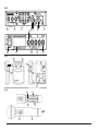
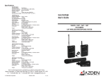
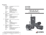
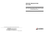
User’s Guide
SPECIFICATIONS
IRR-30P
IRH-15c
2-channel receiver w/power amplifier
Sub-carrier frequencies
Type
Modulation
Signal-to-Noise
Reception sensitivity
Line Input impedance
Line Output adjustment
Audio Output
Power requirement
Size
Weight
2-channel handheld transmitter
Sub-carrier frequencies
Modulation
Microphone element type
Frequency Response
Battery type
Battery life
Size
Weight
IRN-10
IRD-60
2-channel chest-worn transmitter
Sub-carrier frequencies
Modulation
Microphone element type
Frequency response
Ext Mic input impedance
Ext Mic input jack
Ext. Mic Voltage/Current
Mic gain adjustment
Battery type
Battery life
Size
Weight
Dome sensor
Output
Power
Cable requirement
Size
Weight
2.06MHz & 2.56MHz
Super heterodyne – crystal controlled
FM
>75dB A weighted
>25dBμV
32k Ohms ±15%
–∞ ∼ +10dBu
5W x 4 @ 4 ohms
15V DC @ 2.7A (use model BC-30)
8.03" W x 9.19" D x 1.73" H (204 x 233 x 44mm)
2.86lb (1.3kg)
INFRARED CLASSROOM SYSTEM
IRR-30P RECEIVER • IRN-10 MIC/TRANSMITTER
IRH-15c MIC/TRANSMITTER • IRD-60 EXTERNAL SENSOR
2.06MHz & 2.56MHz switchable
FM
Uni-directional dynamic
50-8kHz ±3dB
2-“AA” alkaline( 1.5V x 2 )
2-“AA” rechargeable Ni-MH (1.2V x 2 )
> 6 hours w/alkaline batteries
9.65" x ∼1.375" (245 x ∼35mm)
9.1oz (258g) w/alkaline batteries)
2.06MHz & 2.56MHz switchable
FM
Uni-directional electret x 2
50-9kHz ±3dB
2.2k ohms
Φ 3.5mm
3.5VDC @ 1mA (to power electret mic element)
+6dB ∼ –10dB
2-"AA" Alkaline (1.5V x 2)
2-"AA" rechargeable Ni-MH (1.2V x 2)
> 8hours w/alkaline batteries
3.15" H x 2.75" W x 1.06" D (80 x 70 x 27mm)
4.3oz (120g) -w/alkaline batteries
F Connector
powered by receiver (24V @ 15mA)
RG59 - 75 ohms coaxial
3.94" x 1.18"(100x30mm)
6.00oz (170g) w/mounting bracket
Azden Corporation, 200 Valley Road, Suite 101, Mt. Arlington, NJ 07856
phone – 973.810.3070 • fax – 973.810.3076 • email – [email protected]
© 2008 Azden Corporation
Printed in USA
P1101-01
IRR-30P
G
I
H
K
J
L
M
D
A
C
B
E
F
IRN-10
2
5
6
3
1
4
8
7
IRH-15c
P
R
_
+
_
+
R
O
Q
N
i
S
7
INTRODUCTION
Thank you for selecting the Azden INFRARED system as your wireless classroom solution. We are
confident that it will perform beyond your expectations. For over 50 years Azden Corporation has been
creating technologically advanced products. By taking advantage of the latest in CAD design and SMT
production techniques, Azden’s engineers are able to produce products that exceed the published
specifications and perform well beyond the warranty period.
Azden INFRARED represents a breakthrough in wireless. Instead of the normal radio waves that other
wireless systems use, Azden INFRARED uses invisible light beams in the infrared range. INFRARED’s
enhanced performance assures you of the finest in audio clarity and reliability. The specially selected
high-frequencies provide you with trouble free performance, even in fluorescently lit classrooms.
Infrared (IR) wireless microphone systems are the best solution for classrooms. In today’s RF
saturated world a regular (VHF or UHF) microphone system risks interference from a variety of
other devices and sources. Cell phones, radios, TV, PA systems, police and emergency service
systems, etc., can all interfere with VHF and UHF - but not with IR. Furthermore, infrared is perfect
for classroom audio since, unlike the other systems, IR is short-range and cannot penetrate walls.
This means that your school can have as many classrooms as desired with individual audio
systems, without fear of interference. Since the Azden system is dual-channel, a teacher can have
one microphone and a second person can also have a microphone. In addition, since each
classroom system is on the same pair of channels, teachers can go from room to room without
having to switch microphones.
In the real world, the ability to use multiple systems in the same location without frequency interference will
prove to be a tremendous benefit to you. Using infrared means that the audio generated in your
classroom stays in your classroom. Your discussions cannot be overheard on other systems in other
classrooms.
Designed by professionals - for professionals, Azden INFRARED will provide you with years of worryfree, high-quality performance.
6
ii
TROUBLESHOOTING
TABLE OF CONTENTS
ILLUSTRATIONS ..................................................................................................................... i
INTRODUCTION ...................................................................................................................... ii
IRR-30P RECEIVER ................................................................................................................ 1
Receiver front panel .................................................................................................................. 1
Receiver rear panel .................................................................................................................. 1
Mounting the receiver ................................................................................................................ 1
Overall System Setup ................................................................................................................ 1
IRH-15c MIC/TRANSMITTER ................................................................................................. 2
Batteries and Power Mode for the IRH-15c ................................................................................ 2
Frequency selection .................................................................................................................. 2
Using the IRH-15c ..................................................................................................................... 2
IRN-10 MIC/TRANSMITTER ................................................................................................ 2-3
Batteries for the IRN-10 ............................................................................................................. 2
Frequency selection .................................................................................................................. 2
Using the IRN-10 ...................................................................................................................... 3
External Mic Jack ...................................................................................................................... 3
INTERNAL CHARGING ........................................................................................................... 3
IRD-60 SENSOR ..................................................................................................................... 4
TROUBLESHOOTING ............................................................................................................. 5
SPECIFICATIONS .................................................................................................... back cover
The single most important thing to ALWAYS check when trouble arises are the
batteries. Make sure they are fresh and the POWER LED is glowing brightly.
SYMPTOM
No POWER LED
No audio from IRN-10
No audio from IRH-15c
Intermittent audio
Limited working range
iii
CAUSE
a. Receiver switch is set to OFF - change to ON
b. External 15VDC power source is not connected or is
malfunctioning
c. Dead or very weak battery in transmitter
a. Make sure the volume on the receiver is turned up for the
appropriate channel and the IRN-10 is powered ON
b. If two transmitters are being used, make sure they are set
to different frequency channels
c. Make sure the batteries are fresh or fully charged and
installed correctly
a. Make sure the volume on the receiver is turned up for the
appropriate channel and the IRH-15c is powered ON
b. If two transmitters are being used, make sure they are set
to different frequency channels
c. Make sure the batteries are fresh or fully charged and
installed correctly
a. Make sure there is a clear path between the transmitter
and the receiving sensor. Best results are obtained when
the receiving sensors are mounted high - above
everyone’s head
a. Install extra external sensors
b. If using IRH-15c set the Power Mode to Hi
5
IRD-60 SENSOR
The IRD-60 is an externally-mounted IR sensor. Its purpose is to receive the IR signal from the
IRN-10 and/or the IRH-15c and send it to the input of the IRR-30P for amplification. The ideal
location of the IRD-60 is the center of the ceiling in the room. A cable (RG-59 75 ohm coaxial
cable fitted with “F” connectors) is then run from the IRD-60 to the back of the IRR-30P. The
sensor comes with a mounting-bracket that can be used for mounting to either a solid or drop
ceiling (tiles).
Drop Ceiling Mount:
To mount to a drop-ceiling tile, detach the bracket (9) from the back of the IRD-60 by removing
the screws (10). Next, after removing the ceiling tile from the ceiling grid, determine the position
on the tile panel for the sensor and make a 1 inch hole through the tile (this is for the cable that
will be attached). Then sandwich the tile between the sensor (on the front side) and the bracket
(on the back side). Use the two mounting screws to attach. Last, attach the cable and replace the
tile.
9
10
When mounting to a solid ceiling, first bend the mounting bracket UP at a 90o angle (11). Next,
bend the ends of the bracket to a 90o angle (12). After attaching the cable to the back of the IRD60, use the appropriate screws (13) to attach the bracket to the ceiling.
11
12
The IRD-60 has an acceptance angle of
360o and a working range of 60-70 feet.
13
60-70 ft.
IRR-30P RECEIVER (see illustration on page i)
I. Receiver Front Panel:
A. POWER Switch - turns the receiver ON and OFF. When ON the LED will glow red.
B. Receiving SENSOR - internal receiving infrared sensors.
C. CHANNEL 1/2 Indicator - corresponding LED glows green when receiving CHANNEL 1 or 2.
D. CHANNEL 1/2 Volume - adjusts the output volume for CHANNEL 1 or 2.
E. LINE1/ 2 Volume - adjusts the output volume for LINE 1 or 2.
F. MIC TONE - adjusts the system’s high frequency tone
II. Receiver Rear Panel:
G. EXT. SENSOR INPUT #1 - set the switch on the side of the receiver to EXT to use this connector. This
disengages the front panel SENSOR (B). Set the switch to INT if not using this connector.
H. EXT. SENSOR INPUT #2/3 - attaching external sensors here extends the receiver’s potential working
distance.
I. SPEAKER - the 4 ceiling or wall-mounted speakers are attached here. Carfully follow the + and –
markings.
J. PRE OUT - this is a mono “Line-Level” output. Its level can be adjusted independently.
K. PRE OUT Volume Adjustment - used to adjust the volume from the PRE OUT jack.
L. LINE 1 and LINE 2 Inputs - any external audio source with a standard “Line-Level” output such as a CD
player, VCR or DVD player can be attached here.
M. DC 15V - this is the power input. Plug the small, round connector of the AC-DC adapter (BC-30) in to
power receiver (15VDC @ 2.7A - center positive). Plug the twin-blade end of the adaptor into a
powered 110VAC wall jack.
III. Mounting the Receiver:
As infrared operates “line-of-sight” and can be interrupted by solid objects, it is strongly suggested
that the receiver (or external sensors) be mounted or placed in a location that puts the receiving
sensors above the audience’s heads or any other obstacles.
IV. Overall System Setup:
In general, the IRR-30P receiver is installed near the front of the room facing towards the back and
about five feet above the floor. Four ceiling speakers (if there is a drop ceiling grid) or four wallmounted speakers are installed and wire is run from each of the speakers to one of the SPEAKER
terminals on the back of the receiver. A single IRD-60 ceiling-mount external sensor is installed in the
center of the ceiling and a cable is attched from it to one of the EXTERNAL SENSOR connections on
the rear of the IRR-30P. The teacher wears the IRN-10 and sets it to CHANNEL 1. The IRH-15c,
set to CHANNEL 2, is used as a pass around mic for students. If a DVD player, CD player or video
tape player is used, its audio can be attached to either LINE 1 or LINE 2 on the back of the IRR-30P.
60-70 ft.
360 o
4
1
IRH-15c MICROPHONE/TRANSMITTER (see illustration on page i)
Batteries and Power Mode:
The IRH-15c uses two “AA” batteries. Batteries are placed in the battery compartment after
unscrewing and removing the bottom portion of the microphone handle (S). The IRH-15c can
use either 2 “AA” NiMH*, or Alkaline batteries. Place the two batteries into the transmitter as
shown (R). OBSERVE PROPER POLARITY! Be sure to use FRESH “AA” Alkaline batteries
or, in the case of “AA” rechargeable batteries, be sure that they are FULLY CHARGED
(overnight) before use. Battery life depends on the type of battery and the position of the "HiLo" power switch (O). Maximum battery life is achieved with the switch in the "Lo" position.
*See the section on "Internal Charging" for more battery information.
.
Frequency Selection:
The IRH-15c can be set to transmit on either one of two preset frequencies. This allows two
microphones to be used at the same time in the same room. While it does not matter which
frequency is chosen for the IRH-15c, two transmitters cannot share the same frequency at the
same time. To select the channel, slide the switch (P) as shown on the sticker inside the battery
compartment to the desired position.
Using the IRH-15c Microphone/Transmitter:
After installing fresh batteries and choosing a frequency, simply turn the microphone/transmitter
on by sliding the ON/OFF (N) switch up. The green Power LED above the switch will glow as
will the green LED on the front panel of the IRR-30P receiver which corresponds to the chosen
channel (C). Be sure to slide the Power Switch to OFF when not in use to preserve battery life.
When talking, this microphone should be held close to the user’s mouth, ideally just under the
chin.
Using the IRN-10 Microphone/Transmitter:
After installing fresh batteries and choosing a frequency, simply turn the microphone/transmitter
on by sliding the ON/OFF (1) switch up. The green Power LED (2) will glow as will the green
LED on the front panel of the IRR-30P receiver which corresponds to the chosen channel (C).
Be sure to slide the Power Switch to OFF when not in use to preserve battery life. This
microphone should be worn using the supplied lanyard and be postioned approximately six
inches from the users mouth.
External Microphone Jack:
If an external microphone is desired, plug it into the mic input (6); the internal microphones will
be automatically disabled.
INTERNAL CHARGING
The IRN-10 and IRH-15c can all be used with rechargeable NiMH or regular Alkaline "AA"
batteries. While regular rechargeable NiMH bateries can be charged after taking them out of
the unit, Azden’s 1HR-3U batteries can be charged without removing them. Both the IRN-10
and IRH-15c use a special safety interlock system that prevents the accidental attempt to
charge non-rechargeable (Alkaline) batteries. The special NiMH batteries have a portion of
their wrapping removed so that they can be identified as “rechargeable”. Charging requires
an AC/DC adaptor (Azden's BC-29). To charge, plug the charger adaptor into 110VAC outlet
and plug the connector into the transmitter (4) on the IRN-10 and (Q) on the IRH-15c. Make
sure the transmitter is in the OFF position. Allow a minimum of 12 hours to charge the batteries
(overnight). The NiMH rechargeable batteries can operate either transmitter for 6-8 hours.
IRN-10 MICROPHONE/TRANSMITTER (see illustration on page i)
Batteries:
The IRN-10 uses two “AA” batteries. Batteries are placed in the battery compartment after
sliding the battery compartment door (8) down and away. The IRN-10 can use either 2 “AA”
NiMH*, or Alkaline batteries. Place the two batteries into the transmitter as shown (7). OBSERVE PROPER POLARITY! Be sure to use FRESH “AA” Alkaline batteries or, in the case of
“AA” rechargeable batteries, be sure that they are FULLY CHARGED (overnight) before use.
*See the section on "Internal Charging" for more battery information.
Frequency Selection:
The IRN-10 can be set to transmit on either one of two preset frequencies. This is so that two
microphones can be used at the same time in the same room. While it does not matter which
frequency is chosen for the IRN-10 microphone, two transmitters cannot share the same
frequency at the same time. To select the channel, slide the switch (3) to the desired position.
2
3