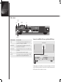
1
D VP1 0 8 0H D D i g i t a l V i d e o P r o c e s s o r u s e r m a n u a l ii Preface Preface Important safety instructions • • • • • • • • • • • • • • Read these instructions. Keep these instructions. Heed all warnings. Follow all instructions. Do not use this apparatus near water. Clean only with dry cloth. Do not block any ventilation openings. Install in accordance with the manufacturer’s instructions. Do not install near any heat sources such as radiators, heat registers, stoves, or other apparatus (including amplifiers) that produce heat. (North America) Do not defeat the safety purpose of the polarized or grounding-type plug. A polarized plug has two blades with one wider than the other. A grounding type plug has two blades and a third grounding prong. The wide blade, or the third prong are provided for your safety. If the provided plug does not fit your outlet, consult an electrician for replacement of the obsolete outlet. Protect the power cord from being walked on or pinched particularly at plugs, convenience receptacles, and at the point they exit from the apparatus. Only use attachments/accessories specified by the manufacturer. Use only with the cart, stand, tripod, bracket, or table specified by the manufacturer, or sold with the apparatus. When a cart is used, use caution when moving the cart/apparatus combination to avoid injury from tip-over. Unplug the apparatus during lightning storms or when unused for long periods of time. Refer all servicing to qualified service personnel. Servicing is required when the apparatus has been damaged in any way, such as power-supply cord or plug is damaged, liquid has been spilled or objects have fallen in to the apparatus, the apparatus has been exposed to rain or moisture, does not operate normally, or has been dropped. Safety warnings • Do not expose the product to dripping or splashing. • Do not place any object filled with liquid, such as a vase, on the product. • Do not place naked flame sources, such as lighted candles, on the product. To avoid interference Do not position the product: • Near strong magnetic radiation, such as near a power amplifier. • Near to a television, or where connecting cables may be subject to or cause interference. WARNING: TO REDUCE THE RISK OF FIRE OR ELECTRIC SHOCK, DO NOT EXPOSE THIS APPARATUS TO RAIN OR MOISTURE This apparatus has been designed with Class 1 construction and must be connected to a mains socket outlet with a protective earthing connection (the third grounding pin). To avoid overheating • Leave at least 10cm around the equipment to ensure sufficient ventilation. Do not position the product: • In direct sunlight. • Near heat sources, such as a radiator. • Directly on top of heat producing equipment, such as a power amplifier. • On a soft surface, such as a carpet, which would obstruct the ventilation holes in the base. The product normally runs warm to the touch. FCC Information (USA Only) CAUTION: Changes or modifications not approved by Meridian/ Faroudja could void the user’s authority to operate the equipment. FCC Warning This equipment generates and can radiate radio frequency energy and if not installed and used correctly in accordance with our instructions may cause interference to radio communications or radio and television reception. It has been type-tested and complies with the limits set out in Subpart J, Part 15 of FCC rules for a Class B computing device. These limits are intended to provide reasonable protection against such interference in home installations. However, there is no guarantee that interference will not occur in a particular installation. If this equipment does cause harmful interference to radio or television reception, which can be determined by turning the equipment off and on, the user is encourage to try to correct the interference by one or more of the following measures: • Reorient or relocate the receiving antenna. • Increase the separation between the equipment. • Connect the equipment into an outlet on a circuit different from that to which the receiver is connected. • Consult the dealer or an experienced radio/TV technician for help. iii Contents Introduction Contents 1 This guide provides full information about unpacking the DVP1080HD Digital Video Processor and connecting it to the other equipment in your system. It also explains how to operate it to get superb results with your video sources and display devices. About the DVP1080HD Technical specifications Installing the digital video processor 1 2 3 This chapter explains how to install the digital video processor. It describes what you should find when you unpack the product, and how you should connect it to the sources and displays in your system. You should not make any connections to the product or to any other equipment in your system while the AC power supply is connected and switched on. Unpacking Applications Video inputs Video outputs Communications connections Connecting power Operating the digital video processor 3 3 4 8 10 10 11 This chapter explains how to operate the DVP1080 Digital Video Processor using the Faroudja remote control. Switching on and off Selecting a video input Remote control Adjusting the image settings Adjusting the aspect ratio Adjusting the image position and borders Displaying test patterns 11 11 12 13 14 15 16 Configuring the digital video processor 17 This chapter explains how to configure the DVP1080 Digital Video Processor using options on the SETUP menu. Displaying the SETUP menu Enabling or disabling video inputs Configuration settings Using profiles Troubleshooting 17 19 19 20 21 This chapter provides suggested solutions to common problems that may occur when installing and using the DVP1080HD. Connecting the processor to the display Connecting sources to the processor Processor setup Processor operation Index 21 24 25 26 29 iv Preface Copyright and acknowledgements Sales and service in the UK Meridian Audio Ltd Latham Road Huntingdon Cambridgeshire PE29 6YE England Tel +44 (0)1480 445678 Fax +44 (0)1480 445686 Sales and service in the USA Meridian America Inc 8055 Troon Circle Suite C Austell GA30168-7849 USA Tel +1 (404) 344 7111 Fax +1 (404) 346 7111 World Wide Web – http://www.meridian-audio.com/ Copyright © 2006-07 Meridian Audio Ltd No part of this document may be copied, photocopied, translated, or reproduced to any electronic medium or machine readable form without prior consent, in writing, from Meridian. Designed and manufactured in the UK by Meridian Audio Ltd. Meridian Audio reserves the right to make changes and improvements to any of the products described in this document without prior notice. Boothroyd|Stuart Meridian, Meridian, and Meridian Digital Theatre are registered trademarks of Meridian Audio Ltd. The Faroudja name and logo, and ‘DCDi by Faroudja’ are registered trademarks of Genesis Microchip Inc. The Faroudja D-ILA1080MF is covered by the following United States patents: 4,030,121, 4,179,705, 4,240,105, 4,262,304, 4,847, 681, 4,864,389, 4,876,596, 4,893,176, 4,916,526,4,967,271, 4,982,280, 4,989,090, 5,014,119, 5,025,312, 5,159,451, 5,237,414. Faroudja equipment is manufactured by Meridian Audio Limited under licence from Genesis Microchip Inc. Country of origin as specified on product label. This guide was produced by Human-Computer Interface Ltd, http://www.interface.co.uk/ Part no: DVP1080HD/1 Introduction This guide provides full information about unpacking the DVP1080HD Digital Video Processor and connecting it to the other equipment in your system. It also explains how to operate it to get superb results with your video sources and display devices. About the DVP1080HD The DVP1080HD Digital Video Processor uses a series of patented image-processing techniques to produce superb image quality with 1920x1080p digital displays from a range of video sources. The DVP1080HD converts 1080i interlaced HD video to a clean, 1080p progressive format for use with digital projectors and plasma displays. It includes full high-definition crossconversion and standard definition processing, with patented technology for de-interlacing, motion tracking, colour fidelity, and image detail enhancement. Although it is ideal for use with digital projectors and plasma displays via a DVI or HDMI input, it can give enhanced image quality with all types of displays, including LCD, DILA, and CRT-based devices. Selectable output profiles The DVP1080HD allows you to create a profile for both 50Hz (PAL) and 60Hz (NTSC) sources for each display in a multiple display installation. Each profile stores 30 different parameters to ensure that the output is properly optimised for each display, so that the DVP1080HD produces the highest quality image with any display and any video source. Inputs In addition to the recommended DVI high-definition digital video input, the DVP1080HD provides a range of analogue video inputs to cater for almost every conceivable video source, including composite video, S-Video, RGB, YPrPb, and HDTV/PC (DV15F). Introduction Introduction Technical specifications Processing 10-bit signal path. 1080i de-interlacing with MADI (Motion Adaptive De-interlacing) and 3:2 pulldown . High Bandwidth mode: Full resolution 1920x1080p (straight deinterlacing without scaling). Enhanced mode: 1080i converted to 1280x720 resolution then scaled to the selected output rate. Inputs Format: NTSC/PAL Composite (BNC): 1V pp S-Video (4-pin DIN): Y - 1V pp, C - 700mV pp Component (BNC) 480i/480p/576i/576p/720p/1080i: Y - 1V pp (SMPTE), Cr - 700mV pp, Cb - 700mV pp RGB (BNC) 480i/480p/576i/576p/720p/1080i: Comp. Sync - 1V pp, RGB - 700mV pp HD/PC Pass-Thru: D15M DVI Input: DVI - I (female) Digital Only (0-255/16-235) Outputs (Progressive) RGBHV: 700mV pp, TTL Sync. H&V Sync: 2.5V pp at 75Ω min. YPrPb: 700mV pp, Sync on Y-1V pp RGsB: Gs - 1V pp, RGB - 700mV pp Digital Video Interface: DVI - I (female) digital only 0-255, HDCP compliant Operational temperature range +5°C to + 40°C with internal temperature warning. Power supply 100-240VAC 50/60Hz Auto Ranging. Power consumption 35W. Dimensions 432mm x 44mm x 318mm (17" x 1.75" x 12.5") WHD (depth includes rear BNC). Allow 80mm (3") at rear for cables. Weight 6.4kg (14lb). Specifications and features are subject to change without notice. Installing the digital video processor Installing the digital video processor This chapter explains how to install the digital video processor. It describes what you should find when you unpack the product, and how you should connect it to the sources and displays in your system. You should not make any connections to the product or to any other equipment in your system while the AC power supply is connected and switched on. Unpacking The DVP1080HD Digital Video Processor is supplied with the following accessories: • Meridian Faroudja remote (in a projector/processor package the remote is packed with the projector). • Rack kit. • Power cord. • This manual. If any of these items are missing please contact your dealer. Note: You should retain the packaging in case you need to transport the unit. Applications In a typical application a high-quality digital video source, such as a Meridian G Series DVD Player, will be connected to the DVI input of the DVP1080HD via an HDMI to DVI cable. The DVI output will be connected to a projector, such as the Meridian D-ILA1080MF1 or D-ILA1080MF2, or a digital display such as a plasma display. The DVP1080HD will automatically select the DVI input and output, and will process the video signal to provide an optimised video image without any additional configuration being necessary. If you have more than one HDMI or DVI source, the DVP1080HD can be used in conjunction with the Meridian HDMAX 421 to allow up to four HDMI or DVI inputs to be connected, including a Meridian DVD Player. The HDMAX 421 is controlled via the COMMs from the Meridian DVD Player, so the appropriate HDMI/DVI source is selected automatically when you select an input on your Meridian system. The DVP1080HD can also cater for additional sources via the component video, S-Video, or composite video inputs. For example, a satellite receiver could be connected to the RGB component video inputs. The DVP1080HD will automatically select the active input, or an input can be selected using a remote control. The DVP1080HD can also be connected to an analogue display device, such as an analogue CRT projector, via the analogue outputs. Although in most applications the DVP1080HD will select the appropriate video input and output without any further configuration, it includes a series of setup menus to allow you to specify the characteristics of each input and output, and customise the video processing options. Each set of settings can be stored as a profile and recalled at a later date, and you can save up to eight different profiles for both 50Hz (PAL) sources and 60Hz (NTSC) sources to cater for different video sources, display resolutions, or colour settings. Installing the digital video processor Video inputs Composite video S-Video Component video D15F ANALOG INPUTS S-VIDEO VIDEO DVI INPUT C/SYNC IR LID PASS-THRU SCREEN ANALOG OUTPUTS MONITOR DVI OUTPUT AC INPUT RED/Pr GREEN/r BLUE/Pb RS-232 OPTION H SYNC V SYNC RS-232 CONTROL DVI/HDMI Use this connector To connect to this S-Video The S-Video output of a video game, satellite, or DVD source if component or DVI outputs are not available. Composite video T he composite output of a low quality source such as a VHS cassette recorder or security camera. Component video The YPrPb or RGBs outputs of a source such as a satellite receiver or DVD player. D15F The high scan rate analogue output of a computer. DVI INPUT The DVI output of a video source using a DVI cable, or the HDMI output of a video source using an HDMI to DVI cable. To connect to an HDMI or DVI source (eg Meridian DVD Player) G91A DVD Player HDMI OUT DVP1080HD Digital Video processor For highest quality connect the HDMI out connection from the DVD player to the DVI input on the DVP1080HD using an HDMI to DVI cable. The DVP1080HD will automatically select the DVI input and no further configuration is necessary. Installing the digital video processor The processor monitors the DVI input and output status and provides the following information on the front panel display: Display Explanation DVI Input signal is supported NO INPUT No signal is detected. DVI PASS-THROUGH VESA rate has been detected and sent to the output A unprocessed. RATE NOT SUPPORTED VESA or non-video rate has been detected but the selected A output is analogue RGB or YPrPb. The input type is auto-detected. Supported video rates for processing are 480i/480p, 576i/576p, and 720p/1080i at 50Hz or 60Hz. VESA rates, including 1080p signals, are sent to PASS-THROUGH only. To connect two or more HDMI or DVI sources DVP1080HD Digital Video processor HDMI to DVI cable HDMAX 421 Satellite receiver HDMI OUT 4 3 2 1 HDMI OUT G91A DVD Player HDMI OUT To select the DVI input • Press DVI on the remote control. To display the signal without processing • Press Bypass on the remote control. A DVI cable must be connected from the processor to the display and the digital output must be activated in the processor SETUP menu. With HDCP encrypted sources, it may take up to 15 seconds for the HDCP authorisation between source and display to be acquired. The display device must be HDCP compatible to view an image. If a switcher is used, it must also be HDCP compliant. HDCP acquisition problems may be displayed as snow or a flashing image on the screen. The DVI input levels and sync type must be matched to the DVI source in the SETUP menu. See Configuring the digital video processor, page 17, for details. Some DVD players may offer a better image using the analogue YPrPb connections with the player set to 480i/576i output. This allows the DVP1080HD to do all the deinterlacing and digital conversion. The Meridian HDMAX 421 allows you to connect up to four HDMI or DVI video sources to a single HDMI or DVI input. In addition, when a Meridian DVD Player is used as the controller, the HDMAX 421 automatically selects the appropriate video input corresponding to the currently selected source. • Connect the output of the HDMAX 421 to the DVI input of the DVP1080HD using an HDMI to DVI cable. • Connect the HDMI out from the G Series DVD Player to HDMI input 4 on the HDMAX 421. • Connect up to three other HDMI or DVI video sources to HDMI inputs 1 to 3 on the HDMAX 421. • In the G Series DVD Player HDMI Options screen set the HDMI Switch option to On. Installing the digital video processor To connect a component video source (eg satellite receiver) Satellite receiver To connect an S-Video source (eg DVD player) DVD player COMPONENT YPrPb/YCrCb S-VIDEO OUT DVP1080HD Digital Video processor You can connect a component source to the YPrPb/RGBs inputs. • Connect an RGBs source to the Cr/Pr/R, Y/Gs, and Cb/Pb/B inputs respectively. • Connect a YPrPb source to the Y/Gs, Cr/Pr/R, and Cb/Pb/B inputs respectively. • Connect a YCrCb source to the Y/Gs, Cr/Pr/R, Cb/Pb/B inputs respectively. The DVP1080HD will automatically detect the type of the component input. Supported video rates for processing are 480i/480p, 576i/576p, 720p, and 1080i at 50Hz or 60Hz. (VESA 640x480 not supported). When using RGBs, be sure to check settings for this input in the SETUP menu. See Configuring the digital video processor, page 17 for details. To select an RGB source • Press RGB on the remote control. To select a YCrCb source • Press YCrCb on the remote control. DVP1080HD Digital Video processor You can connect a video game, satellite receiver, or DVD player to the S-Video inputs if component or DVI outputs are not available. • Connect the S-VIDEO output from the source to the S-VIDEO analogue input on the DVP1080HD. To select the source • Press S-Video on the remote control. Installing the digital video processor To connect a composite video source (eg VHS video recorder) VHS Video recorder COMPOSITE OUT DVP1080HD Digital Video processor This option should only be used with low-quality sources where no other output format is available. • Connect the composite video output from the source to the VIDEO input on the DVP1080HD. To select the source • Press Video on the remote control. Note that older VHS tapes and decks may cause an unstable image. In addition, a distorted image is normal during FFW, RW, and pause. A timebase corrector can be added to help stabilise the image. To connect a computer monitor output • Connect the computer monitor cable to the pass-through input on the DVP1080HD using a D15F cable. This allows high scan rate analogue signals to pass through to the display device. Signals are not processed or transcoded (YPrPb-RGBHV). Analogue cables must be connected from the processor to the display to get an image from this input. If the signal on the input is 5-wire RGBHV, the analogue cables on the output must also be 5-wire RGBHV. Be sure the display device is compatible with the signal type being sent through this input. Use a BNC to D15M breakout cable to connect to the source. To prevent ringing and signal loss do not use D15 to D15 cables longer than 3m (10’). Installing the digital video processor Video outputs Component/RGBHV video D15F ANALOG INPUTS S-VIDEO VIDEO DVI INPUT C/SYNC IR LID SCREEN PASS-THRU ANALOG OUTPUTS MONITOR AC INPUT RED/Pr DVI OUTPUT GREEN/r BLUE/Pb RS-232 OPTION H SYNC V SYNC RS-232 CONTROL DVI/HDMI Use this output To connect to this D15 A computer monitor, or for use as a second video output. Component video RGBHV/YPbPr A high scan rate analogue display with RGBHV or YPrPb analogue inputs. DVI output A compatible digital display that uses single link DVI COMM activity. To connect a DVI projector or display (eg Meridian/Faroudja D‑ILA1080MF1) DVP1080HD Digital Video processor • Connect the DVI output to the DVI input of the projector or display using a high-quality DVI cable. If you are using a Meridian projector: • Connect the RS232 OPTION output from the DVP1080HD to the RS232 input of the projector using the RS232 cable supplied with the projector. Using cables not rated for the resolution being used will result in images with colour sparkles and lines, or no image at all. Always verify the maximum resolution of the cable with the cable supplier. A Meridian HDMAX 121 cable extender may be used at the far end of an HDMI cable to resolve difficulties in many cases. For 1080p, fibre optic cables should be used for lengths over 4.5m (15') (or any cable rated for 1600x1200 resolution. Check with cable supplier). The processor monitors the DVI input and output status and provides the following information on the front panel display: Display Explanation DVI Input signal is supported NO INPUT No signal is detected. DVI PASS-THROUGH A VESA rate has been detected and sent to the output unprocessed. RATE NOT SUPPORTED VESA or non-video rate has been detected but the selected A output is analogue RGB or YPrPb. Installing the digital video processor With HDCP encrypted sources, it can take up to 15 seconds for the HDCP authorisation between source and display to be acquired. The display device must be HDCP compatible to get an image. The SETUP menu offers selections for setting the output type. See Configuring the digital video processor, page 17 for details. To connect a high scan rate analogue display • Connect the R, G, B, H-sync, and V-sync component video outputs from the DVP1080HD to the RGBHV (5-wire) input of the analogue display. Alternatively connect the Y, Pr, and Pb outputs from the DVP1080HD to the YPrPb (3-wire) inputs of an analogue display. RGBHV is highly recommended over YPrPB. Use only high-quality 75Ω cables. RGBHV must use five wires. Be careful not to swap the H and V cables. 10 Installing the digital video processor Communications connections ANALOG INPUTS S-VIDEO VIDEO DVI INPUT C/SYNC IR LID SCREEN PASS-THRU ANALOG OUTPUTS MONITOR DVI OUTPUT IR receiver Trigger Use this connector To connect to this IR LEAD An external infra-red receiver via a 3.5mm stereo jack plug: Tip = +, Sleeve = Ground, Ring not connected. SCREEN A 12V trigger connection for use with an electronic screen or other device requiring a 12V trigger signal. The connection can be programmed for on/off operation in the SETUP menu or via RS232. Use a 3.5mm 2-pin connector Tip = +12V, Sleeve = Ground, 100milliamps maximum. RS232 OPTION RS232 CONTROL Provides switching signals to control some Meridian/Faroudja projector functions including power on/off and 50/60Hz frame rate. Allows the DVP1080HD to be controlled from an external device such as an AMX or Creston control system. AC INPUT RED/Pr GREEN/r BLUE/Pb H SYNC V SYNC RS-232 OPTION RS-232 CONTROL RS232 Option RS232 Control Connecting power Before connecting power, check the rating markings on the underside of the unit to ensure that the product is the correct voltage for your mains supply. • Connect the AC INPUT on the back panel to a suitable mains supply, using the power cord supplied with the DVP1080HD. To disconnect the DVP1080HD from the mains supply at any time remove the appliance connector or the mains plug. For this reason the appliance connector or the mains plug must remain accessible when the apparatus is in use. The socket-outlet should be near the equipment and easily accessible. 11 Operating the digital video processor Operating the digital video processor This chapter explains how to operate the DVP1080HD Digital Video Processor using the Faroudja remote control. Switching on and off To switch on • Press the red power/standby button on the front panel, or the On button on the remote control. To switch to standby • Press the red power/standby button on the front panel or the off button on the remote control. To select an input from the INPUT menu • Press Menu. The front panel display shows: INPUT MENU <PRESS UP/DOWN KEY> • Press V. The display shows the current active input; for example: The front panel display shows: FAROUDJA DVP SERIES LOADING............. ACTIVE INPUT S-VIDEO • Press < or > to step between the active inputs. Selecting a video input The DVP1080HD provides six video inputs: VIDEO, S-VIDEO, RGB, YCrCb, DVI, and PASSTHROUGH. You can select the current video input using the remote control or INPUT menu. The SETUP menu allows you to deactivate unused inputs. If an input is deactivated it will not be visible on the INPUT menu, and the front panel display will show INPUT NOT AVAILABLE if the input is selected with the remote control. To select a video input • Press the appropriate key on the remote control: Video, S-Video, DVI, RGB, YCrCb, or Bypass. After a short delay the currently selected option will be made the active input; for example: ACTIVE INPUT DVI When Bypass is selected, sources connected to the DVI input will be sent to the DVI output unchanged by the processor. Analogue sources connected to the D15 input will be sent to the analogue outputs unchanged by the processor. To deactivate unused inputs See Configuring the digital video processor, page 17. 12 Operating the digital video processor Remote control Digital video projector operation The remote control operates both Meridian DILA projectors and DVP digital video processors. • Press DVP or DILA to select the product you want to control. • Point the infra-red light at the top of the remote control towards the product. To replace the batteries Select projector Select processor Reset a selected menu item to factory setting To work reliably the angle of the beam needs to be within ±30° of centre, and the total distance needs to be less than 7 metres. DILA On Turn processor/projector on Off Turn processor/projector to standby. Hold down or switch projector to cool-down mode Store Profile Preset Navigate menus Enter Return from menu Bypass Menu Display/hide menu Exit YCrCb DVI Select video input Video S-Video RGB 4:3 Letterbox Adjust colour using < or > Display green grid signal for focus adjustment Hide/restore video image Adjust brightness using < or > Illuminate backlight for 10 seconds Colour Tint Detail 1 2 3 Pattern Focus 4 5 7 8 Hide Zoom Bright. 0 Adjust NTSC tint using < or > Adjust image detail using < or > Adjust projector focus* 6 T W 9 Test Cont. • Insert three penlight cells by pressing the negative terminal of each battery against the corresponding spring and snapping into place. Alkaline cells types AAA, UM04 or IECR03 are recommended. Select aspect ratio Anamorphic • Gently press the circular recess near the top of the battery cover on the back of the remote control. • Slide the cover down and off. Select menu item The digital video processor has a sensor on the front panel. The projector may have sensors at the front and rear; see the projector user manual for details. In addition, you may be able to control the projector by pointing the remote control at the screen so the beam reflects back to the projector. DVP Before use, load 3 AAA size batteries into the remote control. If the remote control starts to function erratically, replace the batteries. Display test patterns Zoom projector image* Adjust contrast using < or > Light * Only available with some projectors The correct orientation of the batteries is indicated in the battery compartment. • Replace the battery compartment cover and slide it upwards, engaging the two tabs at the top of the cover with the slots provided at the top of the compartment. • Push the cover up until it clicks shut. When correctly engaged, the cover should sit flush with the rear of the remote control. 13 Operating the digital video processor Adjusting the image settings The options on the PICTURE menu allow you to adjust the picture levels for an optimum image.The DVP1080HD provides the following image adjustments: Brightness, contrast, colour, tint, and detail. Tint is only available with composite or S-Video sources. The setting of each image adjustment is stored for each of the video inputs. To display the PICTURE menu After adjusting a setting you can step between the picture level menus using the A and V keys. The recommended procedure is to adjust the brightness and contrast of the display device first, and then for individual movies or channels. Each picture level should be adjusted for each source using the suggested reference test pattern in the following sections. To adjust the brightness • Press Menu to display the INPUT menu. • Press > to display the PICTURE menu: BRIGHTNESS |•••••• PICTURE MENU <PRESS UP/DOWN KEY> • Press A or V to step between the options on the PICTURE menu. 50 | • Adjust so that the shadows are as dark as possible but subtle details are still visible, such as seeing the wrinkles in a dark suit on a person standing in the shadows. Suggested test pattern: PLUGE. These are described in greater detail below. All the options apart from ADVANCED COLOUR can also be selected by pressing the appropriate key on the remote control. To adjust a picture level • Select the appropriate option on the PICTURE menu, or press the corresponding button on the remote control; Bright, Cont., Colour, Tint, or Detail. The front panel display shows the current setting for the input, from 0-100, together with a graphical slider bar showing the setting: To adjust the contrast CONTRAST |•••••• 50 | • Adjust so the lightest areas are as bright as possible but detail is still visible, such as seeing the details in clouds on a sunny sky. The image is too bright if the lightest bars in the test pattern disappear or start to change colour. Suggest test pattern: 10 STEP GRAY. BRIGHTNESS |•••••• 50 | Either: • Enter the setting using the number keys on the remote control. Or: • Press < or > to decrease or increase the level. To adjust the colour COLOR |•••••• 50 | • Adjust for accurate colours. Film originated sources typically have more subtle colour levels than video originated sources (sports, TV shows). Suggested test pattern: REVERSE COLOR BARS. 14 Operating the digital video processor Adjusting the aspect ratio To adjust the tint TINT |•••••• 50 | Tint is only available with composite or S-Video sources. The aspect ratio options allow you to select the proper aspect ratio of the source being viewed. If the image colour still seems off balance with the tint set correctly the greyscale of the display may need adjusting. Contact your installer for assistance. Note that the correct screen shape must be set in the SETUP menu during initial installation for the settings to function properly; see Configuring the digital video processor, page 17. Suggested test pattern: REVERSE COLOR BAR. The following aspect ratios are available: anamorphic, 4:3, or letterbox. To adjust the detail To select anamorphic aspect ratio DETAIL |• 10 | This enhances the detail in the image. Too much enhancement will produce unnatural looking edges and ringing. The higher quality the source, typically the less enhancement required. With poor digital sources, such as a poorly transferred DVD or a very compressed satellite channel, reducing the detail level can help to make compression artifacts less visible. Suggested test pattern: DVD Movie with a close up of a face in a still frame. Adjust so the face has detail but the edges do not look fake (such as along the bridge of the nose. This selects the correct aspect ratio for sources formatted for widescreen displays, sometimes called Enhanced for Widescreen. DVD players must be set for 16:9 displays for proper screen shape, see the DVD player’s Setup menu. For Meridian DVD players select 16:9 Widescreen in the Display Aspect Ratio menu. To select letterbox aspect ratio • Press Letterbox on the remote control. This selects the proper aspect ratio for sources formatted for the letterbox screen format. To set advanced colour • Select the ADVANCED COLOUR SYS option on the PICTURE menu: ADVANCED COLOR NORMAL • Press Anamorphic on the remote control. SYS • Press > or < to toggle the setting between NORMAL and BYPASS. Advanced colour mode activates colour edge enhancement and cross-colour suppression to improve the image and remove certain video artifacts. This should be set to NORMAL for most sources. With a few movies that contain large amounts of colour, such as animation, these enhancements may cause colour flickering. Set the mode to BYPASS if this occurs. This mode can also be used with anamorphic 2.35:1 (cinema scope) sources when combined with an anamorphic lens on a 16:9 projector. The benefit is that the full resolution of the 16:9 display chip is used to create the active video, improving resolution and light output. The trigger output can be programmed to control the motorised lens attachment. To select the 4:3 aspect ratio • Press 4:3 on the remote control. This selects the correct aspect ratio for sources formatted for a 4:3 screen format. 15 Operating the digital video processor On 16:9 displays the side curtains of the image will be blank. To protect displays from image burning the side curtains can be adjusted from any level of grey from black to full white. Adjust the level in the PICTURE OSD menu. Shifting the image too far to the side can cause the image to be lost or introduce moving horizontal grey bars in the image. Do not view 4:3 images on 16:9 plasma or CRG displays for extended periods of time with the side curtains black. This can cause permanent image burn in. Image burn in is not covered under the warranty. To adjust the border greyscale level Adjusting the image position and borders Use a safe area test pattern to properly align image position and size. • Select the BORDER LEVEL option on the DISPLAY menu: BORDER | LEVEL 00 | The options on the DISPLAY menu allow you to adjust the horizontal and vertical position of the image, and the grey level and size of the image borders. The border level can be adjusted between 0 (black) and 100 (white). This adjusts the grey level of the side curtains when using 4:3 sources on a 16:9 display. To display the DISPLAY menu To adjust the blanking • Press Menu on the remote control. • Select the LEFT BLANK, RIGHT BLANK, BOTTOM BLANK, or TOP BLANK option on the DISPLAY menu: • Press > until the display shows: DISPLAY MENU <PRESS UP/DOWN KEY> • Press A or V to step between the options on the DISPLAY menu. These are described in greater detail in the following sections. To adjust the image position • Select the H POSITION or V POSITION option on the DISPLAY menu: H POSITION |•••••• 25 | The horizontal position can be adjusted between 0 and 50 and the vertical position between 0 and 20. Many digital displays will not allow any image adjustment when using the DVI output; check with the display manual to see if there is a service mode to allow adjustments. Always use image adjust controls in the display device first, if available. LEFT | BLANK 01 | These adjust the amount of blanking for the edges of the image to assist with proper image sizing. Each setting can be adjusted between 0 and 100. • Set the image size and position first before setting the side blanking. 16 Operating the digital video processor Displaying test patterns The PATTERNS menu allows you to display a test pattern for assistance with setting up the Picture and display settings. To display the PATTERNS menu • Press Menu to display the INPUT menu. • Press > to display the PATTERNS menu: PATTERNS MENU <PRESS UP/DOWN KEY> • Press V to display the SELECT PATTERN option and press > or < to switch between OFF (no pattern) or ON (test pattern): SELECT PATTERN OFF • Press V to display the TEST PATTERN option and press > or < to step between the alternative test patterns: TEST PATTERN 100% COLOR BARS When the test pattern is activated the image level adjustments are fixed to reference levels and cannot be changed. Use these patterns to align or test your system. Many patterns are designed for technician use only. For best results all image adjustments should be done with a test DVD from the DVD player and patterns from the satellite box, if available. This ensures that the final image is adjusted for the complete signal path from source, through the processor to the display. 17 Configuring the digital video processor Configuring the digital video processor This chapter explains how to configure the DVP1080HD Digital Video Processor using the options on the SETUP menu. Displaying the SETUP menu The SETUP menu provides a series of options to allow you to configure the digital video processor to suit your specific installation. The display shows: SET: ARE YOU <PRESS STORE SURE KEY> To display the SETUP menu • Press STORE again to change the setting. • Press Menu on the remote control for seven seconds. To specify the active output The display shows the first setup option on the first line of the display and the option’s current setting on the second line of the display: • Select the ACTIVE OUTPUT menu option. SET: NTSC SCANRATE 1280 x 720 You can choose between RGB + DVI, YPrPb, DVI, or RGB: SET: ACTIVE OUTPUT ANALOG RGB + DVI • Press > or < to step between the alternative values for the option. To set the screen shape Except in the case of the SCANRATE options, the value will change immediately to the selected value. • Select the SCREEN SHAPE option: To change the scan rate • Select the NTSC SCANRATE or PAL SCANRATE option: SET: PAL SCANRATE 1280 x 720/50Hz The NTSC scanrate sets the output rate when a 60Hz source is auto detected, and the PAL scanrate when a 50Hz source is auto-detected. Check with the display device manual to determine which output rate to choose. To change the setting: SET: SCREEN SHAPE WIDE SCREEN Use this option to match the aspect ratio of your display device. The options are as follows: Option Description WIDE SCREEN Choose this option when using a 16:9 projector or display, or a 4:3 projector with an anamorphic lens on a 16:9 screen. WIDE 4:3 Choose this option when using a 4:3 projector or display, but want to show a 16:9 image (letterbox); for example, when using a 4:3 projector on a 16:9 screen. 4:3 Choose this option when using a 4:3 projector or display. • Press STORE. The screen shape defaults to AUTO when in high bandwidth mode. 18 Configuring the digital video processor To set the analogue black level To set H&V sync as composite sync • Choose the ANALOG BLACK LVL option: Sets H&V sync as composite sync on the H connector when using analogue RGB output (4wire connection): SET:ANALOG BLACK 7.5 IRE LVL This sets the correct black level for YPrPb DVD sources. It is only available when the component input is selected with a 60Hz source. Many DVD players offer black level options, sometimes called enhanced blacks. For best results the player should be left at its default settings and the analogue black level adjusted in the DVP1080HD. To set the HD input H-adjust Adjusts the horizontal position of High Definition sources (720p/1080i) to match the horizontal position from Standard Definition sources: SET:HD INPUT 25 H-ADJUST Available only when a 1080i/720p signal is detected. Not available in HIGH BANDWIDTH mode. • First align the proper image size and position on the display using a test pattern from a DVD. Use the H/V, L/R and sizing controls in the display device, if available. Use the H/V adjustments in the DVP1080HD OSD if the display does not offer them. • Switch to the HD source and adjust the HD INPUT H-ADJUST to match. The input for the HD source must be selected in order to make the HD H-ADJUSTMENT. Some display devices offer minimal image adjustments when using the DVI inputs. Some HD satellite receivers offer H-adjustments. Those can also be used in conjunction with this function to get the best results. SET: COMP SYNC ON ON H This option is only available when ANALOG RGB OUTPUT is selected and not in HIGH BANDWIDTH mode. RGBHV is recommended for best results. To set the RGB input sync Sets the sync type for the RGB input: SET: RGB INPUT SYNC SYNC-ON-GREEN Only available when the RGB input is selected and not in HIGH BANDWIDTH mode. The composite sync option should be selected when using PAL RGB. To set the DVI input level • Select the DVI INPUT LEVEL option. Only available when the DVI input is selected. This sets the correct input signal level to match the correct DVI input source. The options are explained in the following table: Option Description DVI-VIDEO (16-235) Typical for video sources. If the source is 0-255 and the setting is 16-235 the image will be too bright. DVI-PC (0-255) Typical for digital display devices (the processor’s output is 255). If the source is 16-235 and the setting is 0-255 the image will be dull. 19 Configuring the digital video processor Configuration settings To test what the output is from the source: • Display a 10-step greyscale pattern from a test pattern DVD. The correct setting is when all ten bars are visible and evenly lit. An incorrect setting will produce an image that either looks dull, or the brightest and darkest bars are missing (clipping). The following settings effect the general configuration of the unit and the control inputs and outputs: Setting Description OSD Can be switched between ON and OFF to certify the presence of the on-screen display. OSD TIMER Can be set to between 0 and 255 seconds (default 30). VFD TIMER Specifies how long the front panel display stays on after an operation. Can be set to 0 (off), 1-254 seconds, or 255 = always on (default 30). VFD TIMEOUT LVL Sets the brightness level of the front panel display after the VFD TIMER period has elapsed. • Press < or > to change the input between ENABLE and DISABLE. RS232 ECHO Can be set to ON or OFF to determine whether command echoes are sent back to the RS232 control device. The following inputs are available: VIDEO, S-VIDEO, RGB, YCrCb, DVI, and PASSTHROUGH. BAUD RATE Can be set to 9600, 19200 (default), or 57600 to specify the RS232 communication baud rate. To set the DVI input H-sync SCREEN TRIGGER Can be set to OFF or ON (default) to determine the operation of the 12V external trigger. OFF takes the 12V output low when the DVP1080HD is powered up and ON takes it high. Enabling or disabling video inputs To enable or disable the video inputs • Select the appropriate input option: SET: VIDEO INPUT ENABLE Sets the DVI sync position to normal or wide: SET:DVI INPUT H NORMAL SYNC Only available when the DVI input is selected and a video HD rate input is detected. With some non-standard DVI sources selecting WIDE will correct improper sync timing seen as a horizontal image shift. 20 Configuring the digital video processor Using profiles The NTSC PROFILE and PAL PROFILE options allow you to store the current settings as one of eight profiles for each of 50Hz sources and 60Hz sources. Each profile stores 30 different parameters. To store a profile • Make all the adjustments and settings as required in the SETUP menu. • Select the NTSC PROFILE or PAL PROFILE option as required. • Press < or > to display the profile number you want to use: SET: NTSC PROFILE STORE PROFILE 1 • Press STORE to store the profile. The display will show: SET: NTSC PROFILE COMPLETE To recall a profile • Press Profile on the remote control. The display shows: RECALL <PRESS FACTORY STORE KEY> The second line will show the profile number that was most recently recalled. Either: • Press the number key 1-8 to recall the corresponding profile number or 0 to recall the factory profile. Or: • Press < or > to step through the available profile and press STORE to select one. Up to eight separate profiles can be stored for 60Hz NTSC sources and 50Hz PAL sources. The current input refresh rate will determine which profile is recalled. 21 Troubleshooting Tr o u b l e s h o o t i n g This chapter provides suggested solutions to common problems that may occur when installing and using the DVP1080HD. Connecting the processor to the display Which output scan rate should I choose for my display? The appropriate output scan rate selection is usually determined by the actual native pixel density of a digital display device, or the physical CRT size of an analogue display device (7”, 8” or 9” CRT). Each display device will specify their individual video/computer input capabilities. All display devices will list their specific video/computer input specifications within the User’s Manual, and are typically located within a “Table of Supported Resolutions”, or under similar nomenclature. The following represent basic examples for possible output scan rate selections: Display Type Display resolution DVP1080 scan rate Plasma TV 1366 x 768 1366 x 768 Digital projector 1366 x 768 1280 x 720 CRT projector 7" CRT 8" CRT 9" CRT 1920 x 540 or 1280 x 720 1280 x 720 or 1440 x 960 1440 x 960 or 1920 x 1080 CRT rear screen 480 i/p, 1080i, or 720p 1920 x 540p or 1280 x 720p Note: Occasionally, a digital display device may not actually accept the signal received from the processor at its native pixel resolution. Choose a standard DTV signal in this instance, such as 1280x720 (default setting), or 1920x540 (1080i equivalent). There are sparkles appearing throughout the image when using the DVI output Cable length is too long to support the output resolution selected on the processor • Sparkles may occur if the resolution selected on the DVP-1080 processor has exceeded the ability of the DVI cable to transmit all of the video data (missing bits = sparkles). This is directly dependent upon cable quality (contact cable manufacturer regarding length to resolution specifications). • Unassisted DVI cable lengths to 50ft (15.24m) have been achieved with resolutions of 1024p and lower. • Cable lengths of 50ft (15.24m), or greater, may require a DVI to Fibre Optic cable connection between the processor and display for resolutions higher than 1024p; consult Cable Manufacturer You can also use a Meridian HDMAX 121 extender/booster at the display end to solve problems like this. Contact your Meridian authorised dealer for details. Can the DVP1080 output both an analogue and a digital signal simultaneously? Yes. Four potential SET: ACTIVE OUTPUT modes are available through the DVP-1080 SETUP MENU: Mode Description ANALOG RGB + DVI Both DVI OUTPUT and ANALOG OUTPUTS are active (Default Setting) ANALOG RGB Only ANALOG OUTPUTS are active (RGBHV and MONITOR) DVI Only DVI OUTPUT is active (RGBHV and MONITOR out disabled) ANALOG YPrPb Only ANALOG OUTPUTS are active (DVI output disabled) 22 Tr o u b l e s h o o t i n g Note: When SET: OUTPUT FORMAT / ANALOG YPrPb has been selected through the SETUP MENU, the DVI OUTPUT will be disabled, as the required output signal for DVI is RGB only. Is the DVP-1080 capable of passing/processing an HDCP encrypted DVI/HDMI signal? Yes. However, the DVI INPUT on the display device must also be HDCP compliant to view the image, or the HDCP encryption “handshake” will be broken. If when using HDCP encrypted signals there is digital “snow”, or a message dialog box prompts you to make an alternate connection, you should then check the display’s Operations Manual to verify HDCP compliance. Note: A DVI signal that is HDCP encrypted will deactivate the ANALOG OUTPUTS. Which type of DVI cable should I use from the processor to the display? It is recommended to install a DVI-D, Single-Link cable connection. The physical DVI connection IN and OUT of the DVP-1080 is a DVI-I, Dual-Link connector. However, the DVP-1080 internal pin out configuration is for a DVI-D, Single-Link cable connection. This allows for system connection flexibility. The display device will typically have a DVI-D type connector. What length of DVI cable can I use? High resolution displays require a high quality DVI cable connection from the processor to the display. DVI cables must be rated to support the scanrate and length to be implemented; up to 50 foot non-fibre cables are okay for scanrates 1280x1024 and below. Higher scanrates, such as 1920x1080p, require the DVI cable be rated to at least 1600x1200 for the cable length required. A DVI to fibre optic cable is highly recommended for cable lengths longer than 16 feet (5m). If the DVI cable has exceeded its ability to support the resolution selected, you may experience “sparkles” and/or digital noise throughout the video, or no video at all. To insure installation success, you should always test your connections, prior to installation. Which output connection should I choose: DVI, BNC (RGBHV) or MONITOR (VGA)? When available, the DVI OUTPUT should always be utilized first. However, it is also recommended to route an analogue RGBHV cable to enable system expandability. DVI OUTPUT Choose this connection first, unless the display device does not support this type input connection. BNC (RGBHV) Output Choose the BNC output connections for analogue display devices that do not have a DVI input connection. When SET: ACTIVE OUTPUT / DVI is selected within the SETUP MENU, the ANALOG OUTPUTS are disabled; however, will pass analogue to analogue signals (select appropriate input on the display device). MONITOR (VGA) Output The MONITOR output connection, though convenient, is designed for short cable runs of nine (9) feet, or less. The BNC (RGBHV) output is recommended first. When SET: ACTIVE OUTPUT / DVI is selected within the SETUP MENU, the ANALOG OUTPUTS are disabled; however, will pass analogue to analogue signals (select appropriate input on the display device). Note: There is inherent signal degradation utilizing the MONITOR output for cables runs over nine (9) feet. YPrPb Output (Component) Select this output format only when the display device does not support either a DVI, RGBHV, or 15-pin (VGA) input connection. Select SET: NTSC SCANRATE / 1280x720 or 1920x540 (1080i equivalent), or PAL SCANRATE / 1280x720/50Hz or 1920x1080/50Hz as these scanrates are the only valid Component video output formats which the display will understand; both output scanrates are recognized by the display device as a DTV video signal. 23 Tr o u b l e s h o o t i n g When SET: ACTIVE OUTPUT / DVI is selected within the SETUP MENU, the ANALOG OUTPUTS are disabled; however, will pass analogue to analogue signals (select appropriate input on the display). • Phase picture to center image within the raster area. There is Dark Banding/Streaking while the video image is changing; how do I fix this? • Blank Left, Right, Top and Bottom Blanking to edge of image. The video image is either positioned (Phased) too far to the left/right, or the image is too wide. Though the image may be “filling” the viewable screen area, the display is having difficulty finding the actual Clamp Pulse (sync signal). The display is now “Clamping” to the Peak Whites of the video signal; or rather, “clamping” to video, not the sync pulse. You should recalibrate the display device utilizing a master video test pattern. Utilize a Component (YCrCb) DVD source and a Safe-Area test pattern (AVIA or DVD Essentials calibration DVD). • Image should be clearly seen within the raster area. • Center raster (with image) on the screen. • Increase Left/Right and Top/Bottom Size to the edge of screen. My picture is Magenta or Pinkish in color RGBHV out into YPrPb in = MAGENTA picture. The default analogue ACTIVE OUTPUT of the DVP1080 is 5-wire RGB (RGBHV). If your only video input option to the display is via YPrPb, you must first change the ACTIVE OUTPUT on the DVP-1080 from RGB to YPrPb within the SETUP MENU. Digital Display Device (Plasma, D-ILA, DLP or LCD) Note: The DVI OUTPUT is disabled once YPrPb has been selected; YPrPb is not a valid output format within the DVI domain. • Utilize a “Screen Area” test pattern from a calibration test DVD • Enter the SETUP MENU by pressing Menu on the IR remote for seven seconds • Reduce the video image size until you see the Active Picture area of both the left side and right side of the video image • Press A until the upper LCD display reads either of the following: SET: OUTPUT FORMAT / ANALOG RGB + DVI SET: OUTPUT FORMAT / ANALOG RGB • Center the image on the screen using the positioning controls of the display device only • Digital displays will have sizing controls labeled Pixel Clock, Dot Clock or just Clock, etc. This adjustment will expand/contract the image to from the Right; the Left side of the image should remain relatively fixed to its position • Use Horizontal Size, Positioning controls and Clock adjustment to center/position the image on screen. You will need to utilize all controls to achieve/massage image centering. • Once the image is centered correctly, fully expand the image to the edge of the screen. Analogue CRT Display Device • Use a “Screen Area” setup pattern from a calibration test DVD. • Reduce the image size by 10% to 15%. • Un-blank Left, Right, Top and Bottom Blanking. • Increase BRIGHTNESS to 75%. • Press < or > to select SET: OUTPUT FORMAT / ANALOG YPrPb • Press Menu to return to the USER MENU Note: ONLY select either 1920x540p or 1280x720p scanrates if the display device does not have an available 5-wire RGBHV or D-15 VGA input connection. • If you are connecting the DVP-1080 and display device via RGBHV, and your picture is MAGENTA, you will then need to change the displays input format from COMP (Component) to RGB or PC. • Verify that the output/input cable(s) have not been swapped. • Verify continuity of cable terminations 24 Tr o u b l e s h o o t i n g My picture is Green. YPrPb OUT into RGBHV IN = GREEN picture. The BNC’s (RGBHV), or MONITOR output of the DVP-1080 is connected to the RGBHV, or VGA input of the display device. However, SET: ACTIVE OUTPUT/ ANALOG YPrPb has been incorrectly selected. • Enter the SETUP MENU by pressing Menu on the IR remote for seven seconds. • Press the A until the LCD display reads SET: ACTIVE OUTPUT / ANALOG YPrPb. • Press < or > to select one of the following SET: ACTIVE OUTPUT / ANALOG RGB + DVI SET: ACTIVE OUTPUT / ANALOG RGB • Press Menu to return to the USER MENU Or: • You have selected RGB on the IR remote; press YCrCb on the IR remote. • A Component HDTV (YPrPb) output format has been connected to the PASS-THRU (VGA) input. However, the connection from the DVP-1080 to the display is via RGBHV out or MONITOR out. • Connect the HDTV (YPrPb) output signal to the Component input on the DVP-1080 processor. • Connect a Component (YPrPb) to RGBHV Transcoder between the HDTV source and the analogue PASS-THRU input on the DVP-1080 processor. Note: A transcoder converts an analogue YPrPb signals into an RGBHV signal • Verify that the output/input cable(s) have not been swapped. • Verify continuity of cable terminations. Connecting sources to the processor Can the DVP-1080 process computer signals sent to the DVI INPUT or PASS-THRU input? No. The DVP-1080 will only route a digital or analogue computer signal directly to the pass-through circuitry. Analogue (VGA) When an analogue computer source is connected to the PASS-THRU input, you must connect an RGBHV cable to the display device. The processor will not convert an analogue VGA signal to DVI; the display device must also be capable of the resolution selected on the computer source. Digital (DVI) When a digital computer source is connected to the DVI INPUT, you must connect a DVI cable to the display device. The processor will not convert a digital DVI computer source to RGBHV; the display device must also be capable of the resolution selected on the computer source. There is no video from the DVI OUTPUT when the source is connected to the PASS-THRU input The D-15 PASS-THRU input will only route RGBHV or YPrPb (Component) signals to passthrough via the ANALOG OUTPUTS of the DVP-1080 (Analogue IN = Analogue OUT). It is always recommended to install both an RGBHV cable and a DVI cable to the display device for system expandability. If the display does not have an RGBHV, or D-15 (VGA) input connection, install a 3-wire Component analogue cable to the display; however, only 480i, 480p, 720p and 1080i are valid Component video signals. There is no video from the ANALOG OUTPUTS when the source is connected to the DVI INPUT • A DVI input signal that is HDCP encrypted will deactivate the ANALOG OUTPUTS. HDCP encrypted signals can only connected to the display device using the DVI OUTPUT. • The DVI input originates from a computer source. All VESA computer resolutions are sent directly to pass-through in the same format received (Digital IN = Digital OUT). 25 Tr o u b l e s h o o t i n g Processor setup I changed the output scanrate, but the processor did not register the scanrate selection Changing the output scanrate requires confirmation of the new output scanrate selection. Do not select an output scanrate which exceeds display device capabilities (refer to display device User’s Manual). • Enter the SETUP MENU by pressing Menu on the IR remote for seven seconds • Front Panel LCD display will indicate SET: NTSC SCANRATE and the current RESOLUTION below • Press < or > on the IR remote to select the appropriate output scanrate • Press Store on the IR remote • Front Panel LCD display will indicate ARE YOU SURE? • Press Store to confirm resolution selection. Is SET: NTSC SCANRATE / 1920x1080 an Interlaced or Progressive video signal? The 1920x1080 output scanrate selection is a Progressive Format signal (67.4KHz, 60Hz refresh). Typically, only high resolution displays will accept/resolve this input signal, such as 9”CRT projection, or a digital display device with a native pixel density of 1920x1080. Note: Some digital displays will have a physical pixel density of 1920x1080; however, may not accept this input scanrate. If not, the image may either be split, or half the image is present, or no image at all. Refer to display user’s manual for signal compatibility. If the display does not accept 1920x1080 at 60Hz, then you must choose an alternate resolution the display will understand, such as 1280x720 or 1920x540p (1080i equivalent). Both output resolutions are perceived by the display as a DTV video signal. WARNING DAMAGE may occur if the output scanrate selected within the DVP-1080 SETUP MENU exceeds theability of the display device to show the image. Note: Use the same procedure above during SET: PAL SCANRATE, if applicable (International use) My connection to the display device is analogue. Which SET: ACTIVE OUTPUT format should I choose, RGB or YPrPb? I selected, SET: NTSC SCANRATE / 1920x1080, now there is no video output. SET: ACTIVE OUTPUT / ANALOG RGB + DVI and SET: ACTIVE OUTPUT / ANALOG RGB When DVI is not available, the preferred analogue output selection from the DVP-1080 is always RGB, intimating RGBHV. This produces the highest quality analogue signal, as the processor will have pre-decoded the incoming video signal to its fundamental constituents of Red, Green, Blue, horizontal sync/vertical sync. The 1920x1080 output scanrate is a Progressive Format (67.43kHz), not a 1080i HDTV Interlaced Format (33.75kHz). The display device must be capable of receiving this scanrate (refer to display User’s Manual). When utilizing the DVI OUTPUT, cable lengths to support 1920x1080p should be no greater than 16ft (5m). Cable lengths longer than 16ft (5m) may require a DVI to Fibre Optic connection. DVI cable lengths longer than 16ft (5m) may render an unstable image, “sparkles” throughout the image, or no image at all. Note: Some digital displays may have a physical pixel density of 1920x1080, but will not display the actual 1920x1080p/60Hz signal received by the DVP-1080 processor. Example: 1920x1080, 24p/sF. Think of 24p/sF as an Interlaced signal, whereby, a Progressive HD Segmented Frame is displayed as two individual frames (similar to 1080i), then spliced back together; an Interlaced Format. SET: ACTIVE OUTPUT / ANALOG YPrPb When DVI is not available, and display does not have either an RGBHV or 15-pin (VGA) input connection, select SET: ACTIVE OUTPUT / ANALOG YPrPb from within the SETUP MENU. You must also select either SET: NTSC SCANRATE / 1280x720 or 1920x540 (1080i equivalent), as these scanrates are the only valid Component video output formats which the display will understand; both the 1280x720 and 1920x540 scanrates are recognized by the display device as a DTV video signal. 26 Tr o u b l e s h o o t i n g Processor operation The LCD is displaying an OVERHEAT WARNING. The DVP-1080 processor possesses thermal protection circuitry which actively monitors internal temperature during operation. Excessive heat may cause the processor to malfunction, and/or, shorten product lifespan. • Do not mount processor above power amplifiers or other equipment which generate excessive heat • Allow a minimum of one rack space, above and below the unit, for proper ventilation (1RU or 1.75”). How do I Store a Profile? A stored PROFILE is merely a “Snap-Shot-In-Time” for all settings which have been selected from both the SETUP MENU options (LCD), or the USER MENU (OSD) options, within the DVP1080 processor, and programmed into the processor’s CPU. System SETUP MENU Option (LCD) • Enter the SETUP MENU by pressing Menu on the IR remote for seven seconds • Select all applicable changes required for the intended PROFILE within the SETUP MENU • Press Menu to exit the SETUP MENU • Then, proceed to… • Insure there is adequate system rack ventilation (preempts failure with additional installed equipment) On-screen USER MENU Options (OSD) • Press Menu to view the On-Screen Display (OSD) • LEVEL 1 WARNING / HIGH TEMPERATURE • Adjust all applicable changes required for the intended PROFILE Internal Temperature is exceeding safe operational limits. Steps should be taken to improve ventilation • LEVEL 2 WARNING / HIGH TEMPERATURE Internal Temperature is at critical thermal limits; processor failure may occur. Immediate steps should be implemented, to improve ventilation, and return the unit to optimal operational temperature • LEVEL 3 WARNING / EXTREME TEMPERATURE Internal Temperature has exceeded maximum thermal limitations; processor will shut down. • A LEVEL 3 WARNING will only display for Five (5) Seconds, then the DVP-1080 will shut down • DVP-1080 cannot be powered ON by the front panel power button during this condition • A LEVEL 3 WARNING indication requires the unit first be unplugged to reset • Normal operation resumes once the DVP-1080 has returned to optimal thermal temperature • Under the menu tab INPUT, use V to highlight PROFILE • Press the > to select numeric PROFILE • Press Store. • Press Menu to exit the On-Screen Display. When I select 4:3 on the IR remote, the image is not centered This essentially means the innate 16:9 image from the DVP-1080, when selecting ANAMORPHIC, is not properly centered on the display device. • Utilize a DVD ‘Screen Area’ test pattern (DVD Essentials, AVIA, etc.) • Center, and position the image for a 2.5% over-scan, using the displays sizing and positioning controls. • Once the image has been properly centered, sized and positioned (utilizing the display controls), the 4:3 image will fall-in-to-place and be centered within the 16:9 display area. Note: Do not view a 4:3 images for prolonged periods of time on a 16:9 display; image Burn-In may occur. Image Burn-In is not covered under the warranty. 27 Tr o u b l e s h o o t i n g The DVP-1080 has locked up. How do I reset the processor? There are three options available to re-boot the processor. Level ONE Set the DVP-1080 unit in Stand-By mode; LED indication is RED. Disconnect the power plug from the processor; reconnect the power plug to the processor and allow the unit to re-boot. Level TWO • Enter the SETUP MENU by pressing Menu on the IR remote for seven seconds • Press A on the IR remote once • LCD display will indicate SET: RESTORE FACTORY / <PRESS STORE KEY> • Press Store on the IR remote • Front Panel LCD display will indicate ARE YOU SURE? • Press Store again to confirm Note: This action will clear all programmed PROFILES and reset the DVP-1080 to Factory Defaults. Level THREE Connect to the DVP-1080 RS-232 CONTROL port using Windows HyperTerminal program and a standard Modem Cable). TYPE dvp,setft R denotes a carriage return, or pressing R button on the keyboard Note: This action will clear all programmed PROFILES and reset the DVP-1080 to Factory Defaults 28 Tr o u b l e s h o o t i n g 29 Index A accessories 3 ACTIVE INPUT 11 ACTIVE OUTPUT menu 17 advanced colour, setting 14 ADVANCED COLOUR SYS 14 analogue black level, setting 18 analogue display, connecting to 9 anamorphic, aspect ratio 14 aspect ratio 14 4:3 14 anamorphic 14 letterbox 14 Index connections communications 10 connectors IR LEAD 10 F 4:3, aspect ratio 14 front panel display DVI 5, 8 RS232 CONTROL 10 DVI PASS-THROUGH 5, 8 RS232 OPTION 10 NO INPUT 5, 8 SCREEN 10 contrast, adjusting 13 copyright and acknowledgements iv D D15 8 D15F RATE NOT SUPPORTED 5, 8 H H&V sync as composite sync, setting 18 HD input H-adjust, setting 18 HDMI connecting to 4 video inputs 4 B blanking 15 border greyscale level 15 BORDER LEVEL 15 brightness, adjusting 13 C colour, adjusting 13 communications, connections 10 component video connecting 6 video inputs 4 video ouputs 8 composite video connecting to 7 video inputs 4 configuring 17 settings 19 detail, adjusting 14 display, connecting 8 DISPLAY menu 15 DVI connecting to 4 connecting two or more 5 front panel display 5, 8 DVI input selecting 5 DVI input H-sync, setting 19 DVI input level, setting 18 DVI output 8 DVI PASS-THROUGH front panel display 5, 8 DVI projector, connecting 8 connecting two or more 5 I image borders 15 image position 15 image settings adjusting 13 INPUT menu selecting an input 11 inputs deactivate unused 11 IR LEAD 10 L letterbox, aspect ratio 14 30 Index M R menus RATE NOT SUPPORTED ACTIVE OUTPUT 17 DISPLAY 15 PATTERNS 16 PICTURE 13 SETUP 17 front panel display 5, 8 RGB, selecting 6 RGB input sync, setting 18 RS232 CONTROL 10 RS232 OPTION 10 monitor, connecting 7 N S connecting to 6 selecting 6 video input 4 O satellite receiver operating 11 outputs scan rate, changing 17 SCREEN 10 screen shape, setting 17 SETUP menu 17 signal, display without processing 5 specifications 2 PATTERNS menu 16 picture level, adjusting 13 PICTURE menu 13 profiles 20 recalling 20 storing 20 processor operation 26 processor setup 25 V connecting to 7 S-Video front panel display 5, 8 P connecting sources to the processor 24 connecting the processor to the display 21 VHS video recorder NO INPUT video 8 troubleshooting 21 connecting to 6 T Video selecting 7 video inputs 4 disabling 19 enabling 19 S-Video 4 selecting 11 video outputs 8 Component video 8 D15 8 DVI output 8 Y YCrCb, selecting 6 test patterns displaying 16 tint, adjusting 14