1
INSTALLATION
!
Thermostat / Interface 1F98-1491
WARNING
Thermostat installation and all components of the
control system shall conform to Class II circuits per
the NEC code.
Control 40C01-1400
Control can be mounted on wall or equipment. Control has
four mounting holes. Wall anchors and screws are provided
for mounting on drywall. Drill 3/16 hole for drywall mounting.
If mounting on equipment Do Not Mount inside HVAC
equipment. Only mount on outside of HVAC equipment.
1) Pull the thermostat/interface off the base. Forcing or
prying on the thermostat will cause damage to the unit.
2) Place base over hole in wall and mark mounting hole
locations on wall using base as a template.
3) Move base out of the way. Drill mounting holes. If you are
using existing mounting holes and the holes drilled are
too large and do not allow you to tighten base snugly, use
plastic screw anchors to secure the base.
4) Fasten base snugly to wall using mounting holes and two
mounting screws. Leveling is for appearance only and will
not affect thermostat operation.
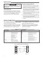
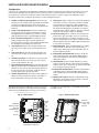
5) Connect wires to terminal block on base (see Figure 1).
6) Push excess wire into wall and plug hole with a fire
resistant material (such as fiberglass insulation) to prevent
drafts from affecting thermostat operation.
7) Carefully line the thermostat up with the base and snap
into place.
WIRING CONNECTIONS
Refer to equipment manufacturers’ instructions for specific
system wiring information. After wiring, see CONFIGURATION
section for proper thermostat configuration.
control will display E (for communication error) until interface
is connected. With power supplied to control, it is normal for
the green system LED to flash periodically.
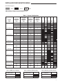
Connect wires as appropriate for HVAC systems (see wiring
diagrams). To power control, connect the 24 V system hot to
R terminal and common to C on left side of control labelled
“Power”. On initial power up the 7 segment LED on the
With interface connected, the 7 segment LED will display
C to indicate the two devices have initiated communication.
C will disappear after approximately 30 seconds when
communication is established.
BLUE EASY INSTALL INPUTS/OUTPUTS
Easy Install 40C01
Control Terminals
Operational / Functional.
R..........................................24 VAC Transformer
RC........................................24 VAC Cooling Transformer
RH........................................24 VAC Heating Transformer
C..........................................24 V Transformer Common
W/E......................................Heating Stage 1
HP Aux/Em Heat Stage 1
W2........................................Heating Stage 2
HP Aux/Em Heat Stage 2
Y...........................................Compressor Stage 1
Y2.........................................Compressor Stage 2
G...........................................Fan Relay
L Terminal.............................System Monitor Compatible
with Comfort Alert Diagnostics
O/B Terminal.........................Changeover Relay Heat Pump
Easy Install 40C01
Control Terminals
Operational / Functional.
DHM.....................................Dehumidification Relay / Connection
DHM2...................................Dehumidification Relay / Connection
HM........................................Humidification Relay / Connection
HM2......................................Humidification Relay / Connection
R...........................................24 VAC to Interface
1...........................................Data to/from Interface
2...........................................Data to/from Interface
C...........................................24 VAC Common to Interface
RJ11.....................................Field configuration hook-up with RJ11
equipped configuration tool.
+...........................................Voltage to Outdoor Sensor
S...........................................Outdoor Sensor Temperature Signal
-............................................Voltage to Outdoor Sensor
Fig. 1 - Thermostat / Interface to control wiring
R
R
1
1
2
2
C
1F98 Thermostat
2
C
40C01Control