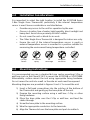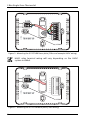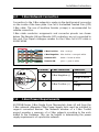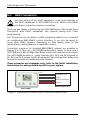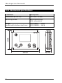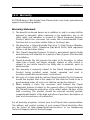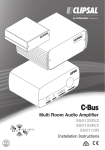
1
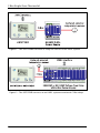
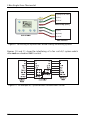
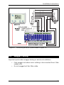
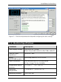
C-Bus Single Zone Thermostat
Installation Instructions
5070THB Series
Clipsal and C-Bus are registered trademarks of Clipsal Australia Pty Ltd
ABN 27 007 873 529.
© Copyright Clipsal Australia Pty Ltd 2007. All rights reserved. This material is
copyright under Australian and international laws. Except as permitted under the
relevant law, no part of this work may be reproduced by any process without prior
written permission of and acknowledgement to Clipsal Australia Pty Ltd.
The information in this manual is provided in good faith. Whilst Clipsal Australia Pty
Ltd (CAPL) has endeavoured to ensure the relevance and accuracy of the
information, it assumes no responsibility for any loss incurred as a result of its use.
CAPL does not warrant that the information is fit for any particular purpose, nor
does it endorse its use in applications which are critical to the health or life of any
human being. CAPL reserves the right to update the information at any time
without notice.
V1.1 Jul 2007
Contents
1.0
Product Range
5
2.0
Important Notes
5
3.0
Description
5
4.0
Installation Considerations
7
5.0
Mounting Instructions
7
6.0
C-Bus Network Connection
9
7.0
C-Bus Power Requirements
9
8.0
HVAC Connection
10
9.0
Megger Testing
13
10.0
C-Bus Programming
14
11.0
Electrical Specifications
15
12.0
Mechanical Specifications
16
13.0
Standards Complied
17
14.0
Warranty
19
C-Bus Single Zone Thermostat
4
Installation Instructions
1.0
Product Range
Catalogue No.
5070THB
Product
Built-in HVAC
Control Relays
C-Bus Single Zone Thermostat
5070THBR
2.0
•
•
•
Important Notes
Ensure the temperature sensor is mounted in a position suitable for
measuring the environment being temperature controlled. This applies
to the 5070THB Series’ internal sensor or to an external C-Bus
temperature sensor (whichever is utilised).
A C-Bus network must be connected to the 5070THB Series unit, to
provide power and a C-Bus system clock.
When the 5070THB Series unit is connected to HVAC equipment, do
not press the power button until C-Bus programming is complete.
3.0
Description
The 5070THB Series C-Bus Single Zone Thermostat is used to control
heating/ventilation/air conditioning (HVAC) equipment, regulating the air
temperature of a particular environment.
The 5070THBR model has built-in relays that can be connected to HVAC
equipment which uses a standard 24 V AC RWG interface. The 5070THB
model connects to HVAC equipment via an external C-Bus Relay unit (such
as the 5508RVF). Apart from this, both models have the same features.
The air temperature is monitored by the unit’s internal temperature sensor
or optionally via an external C-Bus temperature sensor.
Figure 1 shows the system connection of a 5070THBR. A 5500PS C-Bus
Power Supply is used to provide a basic C-Bus network.
In Figure 2, a 5508RVF C-Bus Voltage Free Relay is used to provide the
C-Bus power supply, system clock and burden for the 5070THB. It also
provides the relays which interface with the HVAC equipment.
5
C-Bus Single Zone Thermostat
Figure 1 - The 5070THBR has built-in relays to connect to an HVAC system
Figure 2 - The 5070THB connects to an HVAC system via external C-Bus relays
6
Installation Instructions
4.0
Installation Considerations
It is important to select the right location to install the 5070THB Series
C-Bus Single Zone Thermostat, particularly if the internal temperature
sensor is used. Some considerations are listed below:
•
•
•
•
•
Provide easy access to the unit for operation by the user.
Choose a location free of water, high humidity, direct sunlight and
heavy dust. Avoid close proximity to HVAC outlets.
Do not cover the unit or block its air vents.
The C-Bus Single Zone Thermostat is designed for indoor use only.
Ensure the unit (if the internal temperature sensor is used) or
external temperature sensor is mounted in a position suitable for
measuring the environment being temperature controlled.
no wet
hands
5.0
no cleaner
spray
no
coverage
no direct
sunshine
no
dust
Mounting Instructions
It is recommended you use a standard 84 mm centre mounting C-Clip or
wall box (such as the Clipsal E157) to mount the 5070THB or 5070THBR.
Alternatively, surface mount the unit using appropriate fixing hardware.
Do not recess the unit into a wall, as the side air vents must be exposed.
Mounting diagrams are provided in Figures 3 and 4. To mount the unit:
1) Insert a flat head screw driver into the notches at the bottom of
the Thermostat and gently pry the base plate off the unit.
2) Prepare the mounting surface using a wall box, C-Clip, or other
fixing hardware.
3) Place the base plate over the C-Clip or wall box, and feed the
cables through.
4) Screw the base plate to the mounting surface.
5) Wire the appropriate conductors to the terminals.
6) Align the Thermostat over the base plate and push to reattach.
7
C-Bus Single Zone Thermostat
C-BUS
Rc
RL1
RL2
RL3
Rh
RL4
THIS WAY UP
RL5
Loop
screws
Figure 3 - Mounting the 5070THBR base plate (C-Bus and example HVAC wiring)
HVAC relay terminal wiring will vary depending on the HVAC
system installed.
C-BUS
Rc
RL1
RL2
RL3
Rh
RL4
THIS WAY UP
RL5
Loop
screws
Figure 4 - Mounting the 5070THB base plate (C-Bus wiring)
8
Installation Instructions
6.0
C-Bus Network Connection
Connection to the C-Bus network is made via the dual terminal connector
on the inside of the base plate. Use Cat-5 Unshielded Twisted Pair (UTP)
C-Bus cable. The use of bootlace ferrules (crimps) is recommended for
reliable connection.
C-Bus cable conductor assignments and connector pinouts are shown
below. The Remote ON and Remote OFF conductors are not connected to
this unit. The Clipsal catalogue number for the C-Bus Cat-5 UTP cable is
5005C305B.
C-Bus Positive:
blue + orange
C-Bus Negative: blue & white + orange & white
Remote OFF:
brown + brown & white
Remote ON:
green + green & white
Terminal
C-Bus Connection
C-Bus Negative (-)
Conductors
blue & white
orange & white
blue
C-Bus Positive (+)
7.0
orange
C-Bus Power Requirements
5070THB Series C-Bus Single Zone Thermostats draw 40 mA from the
C-Bus network. Adequate C-Bus Power Supply Units must be installed to
support connected devices. The Network window of a C-Bus Toolkit
project provides a summary of a C-Bus network according to the units
added to the Database. This can be helpful in determining the power
supply requirements of a particular network.
9
C-Bus Single Zone Thermostat
8.0
HVAC Connection
Incorrect wiring of the HVAC equipment could cause damage to
the HVAC equipment or 5070THB Series unit. Refer to the HVAC
installation instructions before connecting.
There are two stages in interfacing the 5070THB Series C-Bus Single Zone
Thermostat with HVAC equipment; the physical wiring and C-Bus
programming.
The Thermostat can be wired to HVAC equipment which uses a standard
air conditioning RWG/RWGY control interface. It can also be wired to
some other HVAC systems, depending on their wiring (refer to the
manufacturer’s wiring diagram or application notes).
Connection scenarios for standard RWG/RWGY systems are provided in
Figures 5 to 9. They use a 5070THBR (with built-in relays). In each case a
5070THB and C-Bus Voltage Free Relay combination may be used instead.
The 5070THBR provides 5 × relay channels (RL1, RL2 and RL3 looped to
Rc; RL4 and RL5 looped to Rh). An external C-Bus Voltage Free Relay may
be used to provide any additional relay channels.
These scenarios are examples only; refer to the HVAC installation
instructions for wiring details specific to your system.
RL1
RL3
RL4
Rc + Rh
press & hold
for setup
press & hold
for timer
Y (compressor)
G (fan)
B (heat activation)
24 V AC
press & hold
for setback
Reverse Cycle A/C
5070THBR
Figure 5 - Connecting to a reverse cycle A/C which uses RWG control
10
Installation Instructions
RL5
Rh
press & hold
for setup
press & hold
for timer
W (heat)
24 V AC
Hydronic Heater
press & hold
for setback
5070THBR
Figure 6 - Connecting to a hydronic heating system which uses RWG control
RL1
RL2
RL3
RL4
Rc + Rh
press & hold
for setup
press & hold
for timer
press & hold
for setback
Pump
Fill valve
Fan speed 1
Fan speed 2
24 V AC
Evaporative Cooler
5070THBR
Figure 7 - Connecting to an evaporative cooler which uses RWG control
RL1
RL2
RL3
RL4
RL5
press & hold
for setup
press & hold
for timer
5070THBR
press & hold
for setback
Rc + Rh
Y (cool)
Open
G1 (fan speed 1)
G2 (fan speed 2)
Close
24 V AC
Fan Coil Cooler
Figure 8 - Connecting to a fan coil cooling system which uses RWG control
11
C-Bus Single Zone Thermostat
Y (compressor/cool)
RL1
G (fan)
RL3
24 V AC
Rc
RL4
Heat Pump (Cool)
RL5
press & hold
for setup
press & hold
for timer
press & hold
for setback
Rh
G (fan)
W (heat)
5070THBR
24 V AC
Gas Furnace
Figure 9 - Connecting to separate RWG based cooling and heating systems
Figures 10 and 11 show the interfacing of a fan coil A/C system which
does not use standard RWG control.
Figure 10 - An example A/C system without standard RWG control
12
Installation Instructions
Figure 11 - Connecting to the A/C system shown in Figure 10
9.0
Megger Testing
Important points when megger testing an electrical installation:
•
•
Only megger test when mains cabling is disconnected from C-Bus
output units.
Do not megger test the C-Bus cable.
13
C-Bus Single Zone Thermostat
10.0 C-Bus Programming
Incorrect programming of the 5070THB Series C-Bus Single Zone
Thermostat could cause damage to the 5070THB unit or HVAC
equipment.
When the 5070THB Series unit is connected to HVAC equipment,
do not press the power button until C-Bus programming is
complete.
Before the 5070THB Series C-Bus Single Zone Thermostat can be used to
control the HVAC system, it must be configured using the C-Bus Toolkit
software. C-Bus Toolkit is available from the Downloads section of the
Clipsal Integrated Systems (CIS) web site (http://www.clipsal.com/cis).
Using C-Bus Toolkit, you must:
•
•
•
give the Thermostat a unique unit address
configure the Plant settings; including groups for the internal
relays (5070THBR model), fan control, cooling, heating, etc.
appropriate for the plant type
configure the Temperature Control settings.
You can also customise various settings on the User Interface and
Temperature Control tabs, such as backlight levels, and temperature guard
settings.
Refer to the C-Bus Toolkit Help documentation for information on the
settings (click the Help button from the relevant tab when editing the
Thermostat within Toolkit).
14
Installation Instructions
Figure 12 - Click the Help button for help with configuring the tab’s settings
11.0 Electrical Specifications
Parameter
Description
C-Bus supply voltage
15 to 36 V DC, 40 mA
Does not provide current to the C-Bus network
C-Bus AC input
impedance
50 kΩ @ 1 kHz
Relays
(5070THBR model)
Each relay rated at 2 A @ 24 V AC
C-Bus connection
One terminal block to accommodate
0.2 to 1.3 mm2 (24 to 16 AWG)
Temperature sensor
accuracy
+/– 0.5 °C
(+/– 0.9 °F)
Operating
temperature
–10 to 50 °C
(14 to 122 °F)
Operating humidity
10 to 95% RH
15
C-Bus Single Zone Thermostat
12.0 Mechanical Specifications
Parameter
Description
Dimensions (W × H × D)
127 × 92 × 27 mm
Mounting Centres
84 mm (horizontal)
60.3 mm (vertical)
Weight
(models with stainless steel facia)
5070THBSS:
265 g
5070THBRSS: 280 g
16
Installation Instructions
13.0 Standards Complied
DECLARATIONS OF CONFORMITY
Australian/New Zealand EMC & Electrical Safety Frameworks and Standards
Model 5070THB and 5070THBR products comply with the following:
Standard
AS/NZS CISPR 14-1
Title
Electromagnetic compatibility – Requirements for
household appliances, electric tools and similar
apparatus – Part 1: Emissions
AS/NZS CISPR 15
Limits and methods of measurement of radio
disturbance characteristics of electrical lighting and
similar equipment
AS/NZS CISPR22
Information technology equipment – Radio disturbance
characteristics – Limits and methods of measurement
European Standards
Model 5070THB and 5070THBR products comply with the following:
Standard
BS EN 60669-2-1
Title
Switches for household and similar fixed electrical
installations – Part 2: Particular requirements – Section
1: Electronic switches
EN 55014-1
Electromagnetic compatibility – Requirements for
household appliances, electric tools and similar
apparatus – Emissions
EN 55015
Limits and methods of measurement of radio
disturbance characteristics of electrical lighting and
similar equipment
EN 55022
Information technology equipment – Radio disturbance
characteristics – Limits and methods of measurement
USA Standards
Model 5070THB and 5070THBR products comply with the following:
Standard
FCC Part 15 Radio Frequency Devices, Subpart B for unintentional radiators.
17
C-Bus Single Zone Thermostat
Other International Standards
Model 5070THB and 5070THBR products comply with the following:
18
Standard
IEC 60669-2-1
Title
Switches for household and similar fixed electrical
installations – Part 2: Particular requirements – section
1: Electronic switches
CISPR 14-1
Electromagnetic compatibility – Requirements for
household appliances, electric tools and similar
apparatus – Part 1: Emissions
CISPR 15
Limits and methods of measurement of radio
disturbance characteristics of electrical lighting and
similar equipment
CISPR 22
Information technology equipment – Radio disturbance
characteristics – Limits and methods of measurement
Installation Instructions
14.0 Warranty
5070THB Series C-Bus Single Zone Thermostats carry a two year warranty
against manufacturing defects.
Warranty Statement
1) The benefits conferred herein are in addition to, and in no way shall be
deemed to derogate; either expressly or by implication, any or all
other rights and remedies in respect to Clipsal Integrated Systems
Product, which the consumer has under the Commonwealth Trade
Practices Act or any other similar State or Territory Laws.
2) The warrantor is Clipsal Australia Pty Ltd of 12 Park Terrace, Bowden,
South Australia, 5007. Telephone (08) 8345 9500. With registered
offices in all Australian States.
3) This Clipsal Integrated Systems Product is guaranteed against faulty
workmanship and materials for a period of two (2) years from the date
of installation.
4) Clipsal Australia Pty Ltd reserves the right, at its discretion, to either
repair free of parts and labour charges, replace or offer refund in
respect to any article found to be faulty due to materials, parts or
workmanship.
5) This warranty is expressly subject to the Clipsal Integrated Systems
Product being installed, wired, tested, operated and used in
accordance with the manufacturer's instructions.
6) All costs of a claim shall be met by Clipsal Australia Pty Ltd, however
should the product that is the subject of the claim be found to be in
good working order, all such costs shall be met by the claimant.
7) When making a claim, the consumer shall forward the Clipsal
Integrated Systems Product to the nearest office of Clipsal Australia
Pty Ltd with adequate particulars of the defect within 28 days of the
fault occurring. The product should be returned securely packed,
complete with details of the date and place of purchase, description of
load, and circumstances of malfunction.
For all warranty enquiries, contact your local Clipsal sales representative.
The address and contact number of your nearest Clipsal Australia office
can be found at http://www.clipsal.com/locations or by telephoning
Technical Support (refer to the back page).
19
Technical Support and Troubleshooting
For further assistance in using this product, consult your nearest
Clipsal Integrated Systems (CIS) Sales Representative or Technical
Support Officer.
Technical Support Contact Numbers
Australia
1300 722 247 (CIS Technical Support Hotline)
New Zealand
0800 888 219 (CIS Technical Support Hotline)
Northern Asia
852 2484 4157 (Clipsal Hong Kong)
South Africa
(011) 314 5200 (C-Bus Technical Support)
Southern Asia
603 7665 3555 Ext. 236 or 242 (CIS Malaysia)
United Kingdom
0870 608 8 608 (Schneider Electric Support)
Technical Support email: [email protected]
Sales support email:
[email protected]
Worldwide contacts are provided at http://www.clipsal.com/locations/
Information and resources are provided at http://www.clipsal.com/cis/
Product of Clipsal Integrated Systems
A Division of Clipsal Australia Pty Ltd
clipsal.com/cis
ABN 27 007 873 529
A member of the Schneider Electric Group
Head Office
12 Park Terrace, Bowden, SA 5007, Australia
Telephone:
(+61) 8 8345 9500
Facsimile:
(+61) 8 8346 0845
Email:
[email protected]
Web:
http://www.clipsal.com/cis/
Clipsal Australia Pty Ltd reserves the right
to change specifications, modify designs
and discontinue items without incurring
obligation and whilst every effort is made
to ensure that descriptions, specifications
and other information in this manual are
correct, no warranty is given in respect
thereof and the company shall not be liable
for any error therein.
F2011
10366491