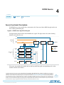
1
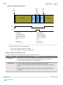
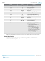
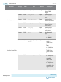
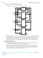
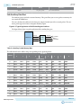
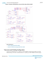
UG-HDMI
2015.05.04
Sink Auxiliary Packet Capture
5-5
Figure 5-4: Auxiliary Data Stream Signal
The figure below shows the relationship between the data bit-field and its clock cycle based on 1-, 2-, or 4symbol per clock mode.
Phase 0
Phase 1
Phase 2
Phase 3
PB24
PB26
BCH3
PB21
PB23
PB25
PB27
PB15
PB17
PB19
BCH2
PB14
PB16
PB18
PB20
PB8
PB10
PB12
BCH1
PB7
PB9
PB11
PB13
PB1
PB3
PB5
BCH0
PB0
PB2
PB4
PB6
HB1
HB2
0
Phase 1
Phase 2
Phase 3
PB22
Byte[8]
HB0
Byte[0]
BCH Block 3
BCH Block 2
BCH Block 1
Output Data
BCH Block 0
Startofpacket
Endofpacket
Valid
Phase 0
Clock
Cycle 1 Symbol
0
-
-
8
-
-
16
-
-
24
Cycle 2 Symbol
0
-
-
4
-
-
8
-
-
12
Cycle 4 Symbol
0
-
-
2
-
-
4
-
-
6
The data output at EOP contains the received BCH error correcting code. The sink core does not perform
any error correction within the core. The auxiliary data is available outside the core.
Note: You can find the bit-field nomenclature in the HDMI Specification Ver.2.0.
Sink Auxiliary Packet Capture
The auxiliary streams transfer auxiliary packets.
The auxiliary packets can carry 15 different packet types.
The module produces 4 valid signals to simplify the user logic.
To simplify user applications and minimize external logic, the HDMI core captures 3 different packet
types and decodes the audio sample data. These packets are: General Control Packet, Auxiliary Video
Information (AVI) InfoFrame, and HDMI Vendor Specific InfoFrame (VSI).
HDMI Sink
Send Feedback
Altera Corporation