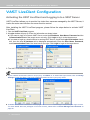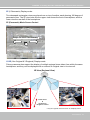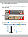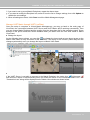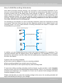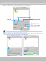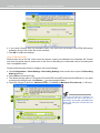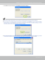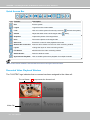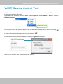
1
Rev. 1.6.1.11 VIVOTEK - A Leading Provider of Multimedia Communication Solutions Table of Contents Revision History������������������������������������������������������������������������������������������������������������������������������� vii Getting Started����������������������������������������������������������������������������������������������������������������������������������������1 Introducing VAST��������������������������������������������������������������������������������������������������������������������������������1 Special Features�������������������������������������������������������������������������������������������������������������������������1 VAST Server and Client Components������������������������������������������������������������������������������������������������2 Usage Scenario����������������������������������������������������������������������������������������������������������������������������������2 Technical Specifications���������������������������������������������������������������������������������������������������������������������3 VAST Server Functionality������������������������������������������������������������������������������������������������������������������4 VAST LiveClient Functionality������������������������������������������������������������������������������������������������������������5 VAST Playback Functionality��������������������������������������������������������������������������������������������������������������6 Minimum System Requirements��������������������������������������������������������������������������������������������������������7 VAST Installation�������������������������������������������������������������������������������������������������������������������������������������8 Installing the VAST Software��������������������������������������������������������������������������������������������������������������8 VAST Server������������������������������������������������������������������������������������������������������������������������������������������ 11 Activating the VAST Server�������������������������������������������������������������������������������������������������������������� 11 How to Configure the Server������������������������������������������������������������������������������������������������������������ 11 How to Stop/Reboot the Server�������������������������������������������������������������������������������������������������������� 11 VAST LiveClient Configuration��������������������������������������������������������������������������������������������������������������12 Activating the VAST LiveClient and Logging in to a VAST Server����������������������������������������������������12 VAST LiveClient User Interface��������������������������������������������������������������������������������������������������������13 Menu Bar�����������������������������������������������������������������������������������������������������������������������������������13 Status Panel������������������������������������������������������������������������������������������������������������������������������13 Quick Access Bar����������������������������������������������������������������������������������������������������������������������14 Live Video Monitoring Window��������������������������������������������������������������������������������������������������14 Hierarchical Management Tree�������������������������������������������������������������������������������������������������15 Camera Control Panel���������������������������������������������������������������������������������������������������������������16 Pan/Tilt/Zoom (PTZ) Control Panel������������������������������������������������������������������������������������16 Two Way Audio Control Panel��������������������������������������������������������������������������������������������17 Language Selection�����������������������������������������������������������������������������������������������������������17 Event Window���������������������������������������������������������������������������������������������������������������������������18 Instant Playback������������������������������������������������������������������������������������������������������������������������19 Audio Control����������������������������������������������������������������������������������������������������������������������������19 How to Manage Devices������������������������������������������������������������������������������������������������������������������20 Insert Cameras��������������������������������������������������������������������������������������������������������������������������20 Insert NVR (Network Video Recorder)��������������������������������������������������������������������������������������24 Insert a Video Server�����������������������������������������������������������������������������������������������������������������26 Update Devices�������������������������������������������������������������������������������������������������������������������������28 Delete Devices from the VAST Server��������������������������������������������������������������������������������������29 i - User's Manual VIVOTEK - A Leading Provider of Multimedia Communication Solutions Batch Insert Devices�����������������������������������������������������������������������������������������������������������������30 View Live Videos�����������������������������������������������������������������������������������������������������������������������34 Dual / Multiple Streams������������������������������������������������������������������������������������������������������34 Refresh�������������������������������������������������������������������������������������������������������������������������������34 Streaming Server���������������������������������������������������������������������������������������������������������������34 Camera Settings����������������������������������������������������������������������������������������������������������������35 Remove Live Video from the Video Monitoring Window�����������������������������������������������������������35 How to Change the VAST LiveClient Layout������������������������������������������������������������������������������������36 Changing the Layout of the Live Video Monitoring Window������������������������������������������������������36 Switch Video Channels������������������������������������������������������������������������������������������������������36 Configure Layout Mode������������������������������������������������������������������������������������������������������36 Rotating Video Pages��������������������������������������������������������������������������������������������������������37 Edit Layout�������������������������������������������������������������������������������������������������������������������������37 Maximize/Minimize the Live Video Monitoring Window�������������������������������������������������������������39 View Live Video on Dual Monitors���������������������������������������������������������������������������������������������40 View up to 64 channels simultaneously�����������������������������������������������������������������������������41 Using different layouts on each monitor�����������������������������������������������������������������������������41 View Live Video with Multiple Monitors�������������������������������������������������������������������������������������42 How to Manage Station��������������������������������������������������������������������������������������������������������������������43 Relay Settings���������������������������������������������������������������������������������������������������������������������������43 Insert Sub-stations��������������������������������������������������������������������������������������������������������������������44 Delete Sub-stations�������������������������������������������������������������������������������������������������������������������47 Update Stations�������������������������������������������������������������������������������������������������������������������������48 How to Manage User Accounts��������������������������������������������������������������������������������������������������������49 The Default User Roles and Permissions of User Accounts�����������������������������������������������������49 Manage a User Account������������������������������������������������������������������������������������������������������������51 Add a New User Account���������������������������������������������������������������������������������������������������51 Permission of the User Account������������������������������������������������������������������������������������������������52 Delete the User Account�����������������������������������������������������������������������������������������������������������53 How to Set up Association Management������������������������������������������������������������������������������������������54 Association Management����������������������������������������������������������������������������������������������������������54 How to Set up Event Management���������������������������������������������������������������������������������������������������56 Event Management�������������������������������������������������������������������������������������������������������������������56 How to Manage the Virtual Matrix����������������������������������������������������������������������������������������������������62 The architecture of VAST Matrix�����������������������������������������������������������������������������������������������62 Installing VAST Matrix Program������������������������������������������������������������������������������������������������63 Launching VAST Matrix�������������������������������������������������������������������������������������������������������������64 Configuration����������������������������������������������������������������������������������������������������������������������65 View Settings���������������������������������������������������������������������������������������������������������������������65 About����������������������������������������������������������������������������������������������������������������������������������65 User's Manual - ii VIVOTEK - A Leading Provider of Multimedia Communication Solutions Exit�������������������������������������������������������������������������������������������������������������������������������������65 VAST Matrix Management��������������������������������������������������������������������������������������������������������66 Matrix Management Settings���������������������������������������������������������������������������������������������66 Manage VAST Matrix through VAST LiveClient�����������������������������������������������������������������67 Matrix View Settings������������������������������������������������������������������������������������������������������������������68 How to Configure the Station General Settings��������������������������������������������������������������������������������69 Server Settings��������������������������������������������������������������������������������������������������������������������������69 Log Settings������������������������������������������������������������������������������������������������������������������������������69 How to Configure Station Network Settings�������������������������������������������������������������������������������������70 Port Settings������������������������������������������������������������������������������������������������������������������������������70 UPnP Settings���������������������������������������������������������������������������������������������������������������������������70 Proxy Settings���������������������������������������������������������������������������������������������������������������������������70 Web Access Settings�����������������������������������������������������������������������������������������������������������������70 How to Edit Recording Groups���������������������������������������������������������������������������������������������������������71 Recording Storage Settings������������������������������������������������������������������������������������������������������71 Default Storage Group Settings�����������������������������������������������������������������������������������������72 Add New Recording Group(s)��������������������������������������������������������������������������������������������74 How to Edit Recording Schedules����������������������������������������������������������������������������������������������������75 Edit Schedule List���������������������������������������������������������������������������������������������������������������������76 Add Schedules�������������������������������������������������������������������������������������������������������������������76 Rename Schedules������������������������������������������������������������������������������������������������������������76 Delete Schedules���������������������������������������������������������������������������������������������������������������76 Load/Save Schedule Templates�����������������������������������������������������������������������������������������77 Edit Camera List������������������������������������������������������������������������������������������������������������������������78 Edit Time Frame List�����������������������������������������������������������������������������������������������������������������79 Add New Time Frames�������������������������������������������������������������������������������������������������������80 Recording Settings�������������������������������������������������������������������������������������������������������������81 The Concept of Repeat Frequency�������������������������������������������������������������������������������������������82 Repeat Frequency: Daily Setting���������������������������������������������������������������������������������������83 Repeat Frequency: Weekly Setting (Day-based)���������������������������������������������������������������86 Repeat Frequency: Monthly Setting (Day-based)��������������������������������������������������������������89 Repeat Frequency: Yearly Setting (Day-based)�����������������������������������������������������������������91 How to Manually Begin /Stop Recording������������������������������������������������������������������������������������������93 How to Edit Scheduled Backup Settings������������������������������������������������������������������������������������������94 Select Backup Source���������������������������������������������������������������������������������������������������������������94 Setup Backup Schedule������������������������������������������������������������������������������������������������������������95 Select Backup Target����������������������������������������������������������������������������������������������������������������95 Other Options����������������������������������������������������������������������������������������������������������������������������95 How to Configure Station Server Settings����������������������������������������������������������������������������������������96 DDNS Settings��������������������������������������������������������������������������������������������������������������������������96 iii - User's Manual VIVOTEK - A Leading Provider of Multimedia Communication Solutions Network Storage Server Settings����������������������������������������������������������������������������������������������97 SMTP Settings��������������������������������������������������������������������������������������������������������������������������98 How to Use the Talk Panel���������������������������������������������������������������������������������������������������������������99 Add a Camera to the Talk Panel������������������������������������������������������������������������������������������������99 Remove a Camera from the Talk Panel����������������������������������������������������������������������������������101 How to Configure E-map Settings��������������������������������������������������������������������������������������������������102 Upload an E-map��������������������������������������������������������������������������������������������������������������������102 User Interface of E-map Settings Page (View Mode)��������������������������������������������������������������103 Quick Access Bar�������������������������������������������������������������������������������������������������������������104 Status Panel���������������������������������������������������������������������������������������������������������������������104 User Interface of E-map Settings Page (Edit Mode)���������������������������������������������������������������105 Device Management���������������������������������������������������������������������������������������������������������������106 Live View Dialog Settings��������������������������������������������������������������������������������������������������������107 Open Live View Dialog�����������������������������������������������������������������������������������������������������107 Send to Single View���������������������������������������������������������������������������������������������������������107 E-map Link������������������������������������������������������������������������������������������������������������������������������108 How to Configure Client Settings��������������������������������������������������������������������������������������������������� 111 Snapshot Settings������������������������������������������������������������������������������������������������������������������� 111 Take a Snapshot�������������������������������������������������������������������������������������������������������������� 112 Recording Settings������������������������������������������������������������������������������������������������������������������ 113 Type 1: Record to EXE ���������������������������������������������������������������������������������������������������� 113 Type 2: Record to 3GP����������������������������������������������������������������������������������������������������� 113 Type 3: Record to AVI������������������������������������������������������������������������������������������������������ 114 Built-in Media Player--EXE����������������������������������������������������������������������������������������������� 117 View Settings��������������������������������������������������������������������������������������������������������������������������� 119 Display Location��������������������������������������������������������������������������������������������������������������� 119 Date and Time Format�����������������������������������������������������������������������������������������������������120 Video Display Mode���������������������������������������������������������������������������������������������������������120 Font Settings��������������������������������������������������������������������������������������������������������������������120 General Settings���������������������������������������������������������������������������������������������������������������������121 System Settings���������������������������������������������������������������������������������������������������������������121 Event Settings������������������������������������������������������������������������������������������������������������������122 Rotation Settings��������������������������������������������������������������������������������������������������������������122 Display Settings���������������������������������������������������������������������������������������������������������������122 Joystick Settings���������������������������������������������������������������������������������������������������������������������123 Enable Joystick����������������������������������������������������������������������������������������������������������������123 Proxy Settings�������������������������������������������������������������������������������������������������������������������������127 How to Use PiP (Picture-in-Picture)�����������������������������������������������������������������������������������������������128 Enable PiP�������������������������������������������������������������������������������������������������������������������������������128 Global View����������������������������������������������������������������������������������������������������������������������128 User's Manual - iv VIVOTEK - A Leading Provider of Multimedia Communication Solutions ROI (Region of Interest)���������������������������������������������������������������������������������������������������129 Digital Zoom In�����������������������������������������������������������������������������������������������������������������129 Snapshot & Print Zoomed In Image���������������������������������������������������������������������������������129 PiP Settings����������������������������������������������������������������������������������������������������������������������129 Multi-touch Mode��������������������������������������������������������������������������������������������������������������130 How to Configure Video Enhancement������������������������������������������������������������������������������������������131 Basic Image Adjustment����������������������������������������������������������������������������������������������������������131 Defog���������������������������������������������������������������������������������������������������������������������������������������133 Apply a Preset Defog Profile��������������������������������������������������������������������������������������������133 Create a New Defog Profile���������������������������������������������������������������������������������������������134 How to Search for a Device on the Hierarchical Management Tree����������������������������������������������136 How to Print a Video Image������������������������������������������������������������������������������������������������������������137 How to Lock LiveClient for Security Concerns�������������������������������������������������������������������������������137 How to Log out from the VAST Server�������������������������������������������������������������������������������������������138 How to Exit VAST LiveClient����������������������������������������������������������������������������������������������������������138 VAST Playback Configuration�������������������������������������������������������������������������������������������������������������139 Activating VAST Playback and Logging in to a Server�������������������������������������������������������������������139 VAST Playback User Interface�������������������������������������������������������������������������������������������������������140 Menu Bar���������������������������������������������������������������������������������������������������������������������������������140 Status Panel����������������������������������������������������������������������������������������������������������������������������140 Quick Access Bar��������������������������������������������������������������������������������������������������������������������141 Recorded Video Playback Window�����������������������������������������������������������������������������������������141 Language Selection����������������������������������������������������������������������������������������������������������������142 Query Panel-- Browsing Page�������������������������������������������������������������������������������������������������142 Query Panel--Time Search Page��������������������������������������������������������������������������������������������144 Query Panel--Event Search Page�������������������������������������������������������������������������������������������145 Query Panel--Log Viewer Page�����������������������������������������������������������������������������������������������146 Video Clips List Window����������������������������������������������������������������������������������������������������������147 Playback Control Panel�����������������������������������������������������������������������������������������������������������148 How to Playback Recorded Video��������������������������������������������������������������������������������������������������149 Select a Recorded Video Clip�������������������������������������������������������������������������������������������������149 Remove Recorded Video Clips from Video Cells��������������������������������������������������������������������151 Timeline Slider Bar and Histogram������������������������������������������������������������������������������������������151 Zoom in / out of the Histogram������������������������������������������������������������������������������������������������152 Synchronous Playback������������������������������������������������������������������������������������������������������������153 Audio Control��������������������������������������������������������������������������������������������������������������������������155 How to Change the Playback Layout���������������������������������������������������������������������������������������������156 Changing the Layout of the Recorded Video Playback Window���������������������������������������������156 Switch Video Channels����������������������������������������������������������������������������������������������������156 v - User's Manual VIVOTEK - A Leading Provider of Multimedia Communication Solutions Configure Layout Mode����������������������������������������������������������������������������������������������������156 Maximize/Minimize the Recorded Video Playback Window����������������������������������������������������157 View Recorded Video with Multiple Monitors��������������������������������������������������������������������������158 How to Backup Recorded Video����������������������������������������������������������������������������������������������������159 How to Search for a Video Clip in a Specific Period of time�����������������������������������������������������������163 How to Search for Events���������������������������������������������������������������������������������������������������������������164 Select Event Category������������������������������������������������������������������������������������������������������������165 Event Category- All Events����������������������������������������������������������������������������������������������165 Event Category- All Motion Events����������������������������������������������������������������������������������165 Event Category- All IVA events����������������������������������������������������������������������������������������166 Event Category- All DI Events������������������������������������������������������������������������������������������166 Event Category- Named DI Events����������������������������������������������������������������������������������167 Start Event Search������������������������������������������������������������������������������������������������������������������168 Backup the Event Videos��������������������������������������������������������������������������������������������������������169 How to Search Logs�����������������������������������������������������������������������������������������������������������������������170 Select Log Category/Log Type/Log Level�������������������������������������������������������������������������������171 Search All Local Logs������������������������������������������������������������������������������������������������������172 Search Login History��������������������������������������������������������������������������������������������������������172 Search Login Activities�����������������������������������������������������������������������������������������������������173 How to Configure Client Settings���������������������������������������������������������������������������������������������������175 Snapshot Settings�������������������������������������������������������������������������������������������������������������������175 Export Settings������������������������������������������������������������������������������������������������������������������������175 View Settings���������������������������������������������������������������������������������������������������������������������������177 Proxy Settings�������������������������������������������������������������������������������������������������������������������������177 General Settings���������������������������������������������������������������������������������������������������������������������177 System Settings���������������������������������������������������������������������������������������������������������������177 Display Settings���������������������������������������������������������������������������������������������������������������177 How to Configure Video Enhancement������������������������������������������������������������������������������������������177 How to Search for a Device on the Hierarchical Management Tree����������������������������������������������177 How to Print a Video Image������������������������������������������������������������������������������������������������������������177 How to Lock VAST Playback for Security Concerns����������������������������������������������������������������������178 How to Log out from the VAST Server�������������������������������������������������������������������������������������������178 How to Exit VAST Playback������������������������������������������������������������������������������������������������������������178 Import and Export Utility����������������������������������������������������������������������������������������������������������������������179 Export Utility�����������������������������������������������������������������������������������������������������������������������������������179 Import Utility�����������������������������������������������������������������������������������������������������������������������������������179 VAST Service Control Tool������������������������������������������������������������������������������������������������������������������180 User's Manual - vi VIVOTEK - A Leading Provider of Multimedia Communication Solutions Revision History Rev. 1.5.2: * VAST now supports Video Servers VS8801 & VS8401, and NVR servers NR8201 & NR8301. * Automatically saves the last layout when the management session is closed (for both LiveClient and Playback). * Added Playback as one of user's previlege options. * A web session with an individual camera can be launched by a double-click on a camera's icon. Rev. 1.6.1: * Added description for Adaptive Frame Rate Adjustment with the new SVC codec cameras. * Added description for Auto Stream Size functionality. * Added functionalities related to FE8171V fisheye camera. * Added description for fisheye-specific screen control and playback functions. * Replaced some description for the changes/improvements made on the user interface. * Modified the graphic size limitation of E-map upload from 5MB to 2MB. Rev. 1.6.18: * Corrected editorial errors and added a conceptual drawing for the SVC-T (Temporal) function. Rev. 1.6.1.11: * Changed the maximum number of channel number in trial mode to 256. vii - User's Manual VIVOTEK - A Leading Provider of Multimedia Communication Solutions Getting Started Introducing VAST VIVOTEK offers the most comprehensive central management software VAST V1.6, designed for managing all VIVOTEK IP surveillance products with intuitive functions and numerous features. It supports management or monitoring of hundreds of cameras and stations in a hierarchical structure of system for monitoring, recording, playback, and event-triggered management with ease-of-use and efficient control. Most particularly, the newest fully scalable feature VAST Matrix offers hundreds of live views for monitoring; with simultaneously 16-channel playback facilitating quick & easy browsing from multiple stations. It performs remote management with a large scale of the server & client structure and constitutes a robust system for stores, banking, and public space. Special Features Powerful Video Wall Solution “VAST Matrix” for Hundreds of Live Views* Intelligent PiP Function -- Digital Zoom In and Multi-touch Mode Integrated with VIVOTEK NVR for Extreme Applications Convenient Remote Access via Client/Server Architecture Powerful Hierarchical Management for Hundreds of Stations* Effective & Reliable Event Trigger Management Real-time 64-channel Live Viewing and Simultaneous 16-channel Playback Multiple Simultaneous Streams for Different Media Platforms Activity Adaptive Streaming for Dramatically Reducing Bandwidth and Storage Space Synchronous/ Asynchronous Playback for Effortless Viewing Extremely Versatile Settings for Recording Storage and Recording Schedule Management Role-based User Management to Enhance Security Operations Efficient Data Backup, Search, and Export Intelligent PTZ/ E-PTZ Remote Camera Control Overall Device Management through Intuitive E-map Feature Instantly Playback Event Recording Supports Web Access via IE and FireFox Built-in Instant Player for Playback Supports Post-Video Enhancement and Defog Accessible through NAT Using the Public IP Supports Two Way Audio Supports Auto Stream Size Supports SVC adaptive frame rate setting * The number of linked devices will depend on the license on the key dongle. * The ability to extend devices is also subject to the network bandwidth and computer performance. User's Manual - 1 VIVOTEK - A Leading Provider of Multimedia Communication Solutions VAST Server and Client Components Remote Server Structure There are four components in VAST: oneClient server component--VAST Server, three client components--VAST LiveClient, VAST Playback, and VAST Matrix. VAST Server provides a centralized management for video recording. VAST LiveClient VAST Playback site Web Console VAST LiveClient is a client program for the user to login and modify the server's configuration, edit the server's Login recording storage, schedules and many other functions on the server; VAST Playback is VAST CMS Server another client program for theLogin user to login and browse the recorded video database and video (Root station) clips related to specific events on the server. Software NVR Usage Scenario VAST / ST7501 Server (Sub-stations) The powerful management scalability of VAST makes it suitable for managing small- to largescale structures. For users that manage only a few cameras, we recommend installing the client and server components on the same computer.Unlimited A hostNo.with all of the three components installed is recognized of Network Cameras , Video Servers... as a stand-alone site. All the functions can be simultaneously performed on one single site. Router Local Server Structure Stand-alone site VAST Server VAST LiveClient VAST Playback Network Cameras Router For users who manage large-scale surveillance deployments, please plan the hierarchical structure first. Then you can start to add cameras to each station and connect these sub-stations to the root station. The whole hierarchical management system is thus constructed. Remote Server Structure VAST LiveClient Client VAST Playback Web Console Login VAST CMS Server Login (Root station) Software NVR VAST / ST7501 Server (Sub-stations) Router Unlimited No. of Network Cameras , Video Servers... 2 - User's Manual Local Server Structure Stand-alone site VIVOTEK - A Leading Provider of Multimedia Communication Solutions Technical Specifications Hierarchical Station Management Architecture Internet Client VAST Server Client Internet Internet VAST Server VAST Server Internet Internet Technical Specifications General Architecture .Max channel: Unlimited .Max channel per hard disk: 32 channels .Max frame rates per second (per hard disk): 960 (32ch x 30 fps,VGA) .OS: Windows 7 Professional Windows XP Professional Windows Server 2003 Windows Vista Business .Supported DBMS: SQL server, PostgreSQL .System: Client/Server .Remote client: Yes .Web access: Windows IE6, IE7, IE8, FireFox 3.5 .Hierarchical: Yes .Program: LiveClient, Playback Depend on H/W spec Protocol .Client/Server communication protocol: HTTP tunnel with XML content .Encryption between Client/Server: Encrypt with AES Playback Codec .Video compression: MPEG-4, MJPEG, H.264 .Audio compression: AAC, GAMR, G.7221, G.729A, G711, G711A Recording .Recording types: Manual, Scheduled, Event trigger .Event trigger sources: Motion, Tampering, DI/O, PIR, IVA, and Temperature .Multiple hard-disks: Yes (Each group can utilize several disks) .NAS/SMB: Yes .Media file format: ISO base media file format .Cyclic recording: Day based, Spatial based Security .Authentication system: Private account with password .Account role type: 5 levels of user roles .Max channel number: 16 .Type: Asynchronous, Synchronous .Event search: Yes .Mount local database Video Enhancement .Post-video adjustment: Brightness, Contrast, Saturation, Hue .Video enhancement: Fog, Rain, Snow, Fire/Smoke Event Management .Live event awareness: Yes (Display in the event window) .Trigger sources: Motion, Tampering, DI/O, PIR, IVA, and Temperature .Actions: Email, Start to record, Move to preset location, Set DO, GSM short message, Send CGI command Other Exporting .Camera configuration: Web-based configuration page embedded in .Exporting format: AVI, EXE, 3GP .Snapshot format: BMP, JPEG .Source: Live view and media files .Multi-lingual user interface: Nine preset languages, additional LiveClient for all functions customized languages (English, French, German, Italian, Spanish, Traditional Chinese, Backup Simplified Chinese, Japanese, Portugal) .Backup types: Manual, Scheduled .PTZ control: Joystick support, Click on Image, PTZ panel, Layout-live .Layout types: 1x1, 2x2, 1+5, 3x3, 1+12, 4x4, 5x5, 1+31 .Drag & Drop: Yes .Layout sets: Yes (Switch between different layout sets) .Automatically add a newly-inserted device to the layout: Yes Keyboard shortcut .Supports E-Map .Supports all VIVOTEK Network Camera .Supports two way audio All specifications are subject to change without notice. Copyright c 2010 VIVOTEK INC. All rights reserved. VIVOTEK INC. 6F, No.192, Lien-Cheng Rd., Chung-Ho,Taipei County, Taiwan |T: +886-2-82455282| F: +886-2-82455532| E: [email protected] VIVOTEK USA, INC. 470 Lakeside Drive Suite C, Sunnyvale, CA 94085 USA |T: 408-773-8686| F: 408-773-8298| E: [email protected] Ver 0.6 User's Manual - 3 VIVOTEK - A Leading Provider of Multimedia Communication Solutions VAST Server Functionality Centralized management site for all the logged in clients Maintain the configuration of the hierarchical management list Hundreds of video recording channels Store recorded data onto multiple networked or local hard disks Live video for the local/remote LiveClient users Retrieval of recorded video for the local/remote Playback users Zero latency database recovery LiveClient is the management interface to your VAST server. The server-related settings are made via the VAST LiveClient utility. The convenient and intuitive user interface on VAST LiveClient provides access to camera, live monitoring, and recording configurations. 4 - User's Manual VIVOTEK - A Leading Provider of Multimedia Communication Solutions VAST LiveClient Functionality Server function control Hierarchical station management User account management Recording storage management Recording schedule management Recorded data backup Event trigger management Flexible video live view layout Dual screens for a maximum of 64 or more channels for simultaneous monitoring 1x1, 2x2, 1+5, 3x3, 1+12, 4x4, 5x5, 1+31 monitoring layouts Multiple video viewing pages Virtual Matrix for video wall display Intelligent PiP function E-map for overall management Network storage for recorded video Convenient switching among multiple monitors PTZ / E-PTZ operation panel for camera control Supports two way audio Instant playback for event recording Supports joystick control Remote configuration for network cameras User's Manual - 5 VIVOTEK - A Leading Provider of Multimedia Communication Solutions VAST Playback Functionality Browse the database of recorded video from the server Flexible video playback layout Maximum 16 channels with simultaneous playback 1x1, 2x2, 1+5, 3x3, 1+12, 4x4 video playback layouts Supports powerful playback functions 1/8x, 1/4x, 1/2x slow-down playback 2x, 4x, 8x, 16x, 32x, 64x video playback speed Intelligent PiP function Supports convenient evidence and data exporting Export media files of recorded video Supports snapshot and print out Supports convenient switch among multiple monitors Search engine: Time search Event search Log search Playback while recording Support synchronous/ asynchronous playback 6 - User's Manual VIVOTEK - A Leading Provider of Multimedia Communication Solutions Minimum System Requirements Before installing the VAST software, please make sure your system meets the following recommended minimum system requirements. If you would like to install ST7501 Server only, please follow the requirements as below: Server Windows Server 2000, 2003, 2008 / Windows XP Professional (32 and 64 bit), Windows Vista Business (32 and 64 bit), Windows 7 (32 and 64 bit) Channels Below 32 channels Above 32 channels Core 2 Duo E6400 Core 2 Quad Q6600 CPU 2.13GHz or above 2.4GHz or above RAM 2 GB or above 3GB or above Network Interface Card Ethernet, 1 Gbit recommended Graphics Adapter AGP or PCI-Express, minimum 1024×768, 16 bit colors Hard Disk Type ATA-100, SATA, SCSI, SAS (7200 rpm or faster) in NTFS format Hard Disk Space 750 GB free * Operating System If you would like to install both the server and client programs, please follow the requirements as below: LiveClient and Playback Operating System Channels CPU RAM Windows Server 2000, 2003, 2008 / Windows XP Professional (32 and 64 bit), Windows Vista Business (32 and 64 bit), Windows 7 (32 and 64 bit) Below 16 channels 16 ~ 32 channels 32 ~ 40 channels Above 40 channels Core 2 Duo E6400 Core 2 Duo E8600 Core 2 Quad Q6600 Core i7 2.13GHz or above 3.33GHz or above 2.4GHz or above 2 GB or above 3GB or above 4GB or above Network Interface Card Ethernet, 1Gbit recommended Graphics Adapter Hard Disk Type Hard Disk Space AGP or PCI-Express, minimum 1024×768, 16 bit colors Minimum 128MB Video RAM, 512MB recommended ATA-100, SATA, SCSI, SAS (7200 rpm or faster) in NTFS format 750 GB free * Only users with Administrator privileges can install or use VAST on a Windows Vista system. The required hard disk space will depend on the video settings, the number of network cameras and recording group settings. Please add more hard disks if you want to extend the system. Below are approximate numbers for a week-long recording. The actual storage space required also depends on imaging parameters, e.g., a complex retail environment that involves many moving objects requires more pixel data to be transmitted over network than a simple environment such as a parking lot. 32-CH, VGA, about 1 week recording: 750 GB 64-CH, VGA, about 1 week recording: 1TB x 2 32-CH, 2-megapixel, about 1 week recording: 2TB x 2 64-CH, 2-megapixel, about 1 week recording: 2TB x 4 User's Manual - 7 VIVOTEK - A Leading Provider of Multimedia Communication Solutions VAST Installation Installing the VAST Software 1. Run VAST_Setup.exe on your computer. Click I ACCEPT the License Agreement and specify a location to install the program. 2. Select the items you want to install, then click Next to continue. If you want to install both VAST Server component and Client components, please follow the steps below to install the database. Server component Client components 3. Assign a username and password for the VAST Server and click Next to continue. Please record the user name and password for login later. 8 - User's Manual VIVOTEK - A Leading Provider of Multimedia Communication Solutions 4. Install a database on your server. There are two options--PostgreSQL (8.2 version or above) or SQL server (2005 express version or above). In order to avoid conflicts among different databases, we suggest you remove the original database from your host. Then follow the instruction below to install PostgreSQL or SQL server. PostgreSQL Please note that PostgreSQL may interrupt an antivirus program. Follow the steps below to install PostgreSQL Server: a. Select PostgreSQL from the drop-down list and assign a password. VAST server will by default store the recorded media file under c:\Recording. Click Browse to change the path if you plan to store the video data to another folder. Then click Next to continue. b. If you do not have PostgreSQL, select the first option to begin the installation. If you already have PostgreSQL installed on your host, select the second option to enter the related information. c. Wait for the installation process to complete, then click Close to exit the installation program. User's Manual - 9 VIVOTEK - A Leading Provider of Multimedia Communication Solutions SQL Server Follow the steps below to install SQL Server: a. Select SQL Server from the drop-down list and assign a password. VAST server will by default store the recorded media file under c:\Recording. Click Browse to change the path if you plan to store the data under another path. Then click Next to continue. b. If you do not have SQL server, select the first option to begin the installation. If you already have SQL server installed on your host, select Windows authentification or SQL Server authentification. (Username and Password may be necessary according to the settings when you install the SQL server.) Click Install to begin the installation. c. Wait for the installation process to complete, then click Close to exit the installation program. Once you have created a user account for a VAST station, you can login to VAST Server from any computer over the network through LiveClient and Playback. 10 - User's Manual VIVOTEK - A Leading Provider of Multimedia Communication Solutions VAST Server Activating the VAST Server VAST Server is a service program that will run automatically when your VAST station starts. Users can also deselect the Auto launch option at windows startup on the VAST Service Control program tray. The program tray icon can be located on Windows tool bar. How to Configure the Server Please follow the steps below to configure the VAST Server: 1. Find a local/remote computer that has installed VAST LiveClient. 2. Activate VAST LiveClient and login to the target VAST Server. 3. Configure the server using the VAST LiveClient user interface. How to Stop/Reboot the Server Please follow the steps below to stop/reboot the server: 1. Click on the VAST Service Control program tray icon in the toolbar. 2. There are 3 options: Start Service, Stop Service, and Restart Service. It’s selectable by a right-click on the Service Control program tray icon. User's Manual - 11 VIVOTEK - A Leading Provider of Multimedia Communication Solutions VAST LiveClient Configuration Activating the VAST LiveClient and Logging in to a VAST Server VAST LiveClient allows you to monitor live video from cameras managed by the VAST Server; it is also the main user interface for server function control. After installing the VAST LiveClient program, please follow the steps below to activate VAST LiveClient: 1. Run the VAST LiveClient program. 2. A Login window will pop up. Enter the information as shown below: If you want to login to a remote VAST Server, enter the IP Address, User Name, Password and the Communication Port of the target server correctly. Click Login to log in to the target server. If you want to login to a local host that is running VAST Server, check the Login local station checkbox, then the local IP Address will be displayed automatically. Enter the User Name, Password, and Communication Port of the local server for login. Click Login to login to the target server. 3. The VAST LiveClient monitoring window will prompt. If your network environment need to set up proxy, click More >> to extend the login window, then click Proxy Settings to open the dialog. Then enter related information to link to your proxy server. Available functions of the VAST LiveClient program will be enabled according to the role of your login account. For more details about the privileges of the user account, please refer to How to Manage User Accounts on page 57. 12 - User's Manual VIVOTEK - A Leading Provider of Multimedia Communication Solutions VAST LiveClient User Interface E B G F A C D H A. Menu bar B. Quick access bar C. Hierarchical management tree D. Camera control panel (PTZ / Two way audio / Instant Playback control panel) E. Live view window F. Matrix view window G. Status panel H. Event window Menu Bar Menu Item Drop-down Options System Lock / Enable Click On Image (Disable Click On Image) / Language / Second View / E-map / Launch Playback / Logout / Exit Edit Manually Begin Recording (Stop Manual Recording) / Snapshot / Print / Record to EXE (3GP, AVI) / Snapshot Zoomed Image / Print Zoomed Image / Find View PTZ Panel / Two Way Audio Panel / Instant Playback Panel / Event Window / Full Screen / Minimize / Matrix View Camera Management (Insert Camera / Update Camera / Delete Cameras / Batch Insert Cameras) / Station Management / User Management / Association Management / Event Management / Virtual Matrix Management (Matrix Management / Matrix View Settings) / Station Settings (General Settings / Network Settings / Recording Storage Settings / Recording Configuration Schedule Settings / Scheduled Backup Settings / Server Settings / Relay Settings) / Client Settings (Snapshot Settings / Recording Settings / View Settings / General Settings / Joystick Settings / Proxy Settings / PiP Settings) / Video Enhancement (Basic Image Adjustment / Defog) Layout Start Rotating (Stop Rotating) / Save to / Delete / Choose Help About / License Status Panel User Name Station Name (IP Address) Login Time (yyyy-mm-dd hh:mm:ss) Current Time (yyyy-mm-dd hh:mm:ss) User's Manual - 13 VIVOTEK - A Leading Provider of Multimedia Communication Solutions Quick Access Bar Icon Function Description Exit Exit the system Logout Log out from the current station Lock Click to Lock the system for security concerns ( Volume Adjust the audio volume of the current video ( Snapshot Capture pictures from the focus live video cell Print Print out the pictures of focus live view window or all live video cells Record to Media Record media in EXE/3GP/AVI format ( Alert Sound Play sound when an event triggers Switch Screen Switch the current window to another screen Adjust SVC Level Dynamically adjust the SVC control over frame rates Unlock the system) Mute) Recording Media) Remove All Connections Remove all live videos from the live view window Layout Change the layout of the live view window Full Screen Maximize the live video cell Page Up Switch to the previous live view page Page Down Switch to the next live view page Start / Stop Rotating Start or stop live view layout rotating Some buttons will be disabled if the selected devices do not support the corresponding functions. Live Video Monitoring Window The "VIVOTEK" logo is displayed where no camera has been assigned to a video cell. The red frame ( Video Cell 14 - User's Manual ) represents the current selection. VIVOTEK - A Leading Provider of Multimedia Communication Solutions Hierarchical Management Tree Root Station Name (IP address) Connected devices listed under the root station Camera name (IP Address) Connected devices that have been assigned to the default recording storage Layout list Sub-station Name (IP address) Icon Description A station (The host that’s installed with VAST Server) A station (The host that’s installed with ST7501 Server) / VIVOTEK fixed network camera Red dot signifies that the camera is recording. / VIVOTEK PTZ network camera Red dot signifies that the camera is recording. / VIVOTEK dome network camera Red dot signifies that the camera is recording. / VIVOTEK fisheye network camera Red dot indicates that the camera is recording. / VIVOTEK video server Red dot signifies that the video server is recording. / Digital input on / off / Digital output on / off A layout of the live monitoring window A station that’s not able to be connected currently. A device that’s not able to be connected currently. User's Manual - 15 VIVOTEK - A Leading Provider of Multimedia Communication Solutions Camera Control Panel Pan/Tilt/Zoom (PTZ) Control Panel Top left Left Bottom left Zoom out Focus near Close Start to auto pan Up Top right Return to home position Right Bottom right Down Auto focus Zoom in Focus far Open Auto iris Start to auto patrol Stop auto panning/patrolling Drop-down list of preset positions There are two types of PTZ control: Digital (E-PTZ for megapixel cameras) and Mechanical (PTZ cameras or fixed cameras with camera control via RS-485). If the connected cameras support PTZ/E-PTZ function, the PTZ option(s) will appear on the drop-down list. For detailed camera control settings, please refer to the user's manual of VIVOTEK network camera . Click System > Enable Click On Image to use the mouse for the control of the PTZ and e-PTZ functions in the video cells for linked cameras. An icon will appear in the video cell as shown below. You can control the PTZ function through joystick as well. For more information regarding to the joystick configuration, please refer to instructions on page 132. 16 - User's Manual VIVOTEK - A Leading Provider of Multimedia Communication Solutions Two Way Audio Control Panel The two way audio function allows the user to remotely communicate with people nearby the network camera. Selected device that can use the two way audio function Click to play sound from the camera Click to talk Remove all cameras from the Talk Panel Select sound from the file list Click to play the selected sound on the client's side Click to adjust volume For detailed information about How to Use the Talk Panel, please refer to page 107. Only cameras that come with the two way audio function can be added to the Talk Panel. Language Selection VAST currently supports multi-lingual user interfaces including: English, Deutsch, Español, Français, Italiano, 日本語, Português, 簡体中文, 繁體中文. If you want to select another language for the interface, please click System > Language on the menu bar to select the desired language. Please note that if you want to change the language option, a message will prompt to remind you to restart the system. If you want to use "User Defined" language, please prepare images and language strings, and upload the files to the following folders: ...\VAST\Client\LiveClient\language\zz_UD (language string) ...\VAST\Client\LiveClient\image (images) User's Manual - 17 VIVOTEK - A Leading Provider of Multimedia Communication Solutions Event Window Click View > Event Window to open a window showing the real-time information for event triggers. If you want to hide this window, deselect this option on the menu bar. Event Window The default event window is fixed on the bottom of the LiveClient. If you want to change the event window as a popup page, please click Configuration > Client Settings > General Settings to switch the modes. The Type field in the event window shows the event category and another field Description displays the percentage of motion in the detection window. You can go to the Configuration setting page of the connected device to set the percentage. Video(TCP-AV) For more information about DI/DO settings, please refer to Association Management on page 62. 18 - User's Manual VIVOTEK - A Leading Provider of Multimedia Communication Solutions Instant Playback Check View > Instant Playback to open the window on the panel. Uncheck this item if you want to hide this window. Instant Playback Window with a slide bar, play, pause, and stop function The recorded media that was triggered by an event will be indicated with an icon. You can double-click an event on the list to playback the recorded video. Each event contains about 20-seconds recorded video clip. (The default recording data of an event is 20 seconds. For more information about event recording, please refer to page 81.) Audio Control The audio function will be enabled if the device is equipped with an internal or external microphone. For detailed audio control settings, please refer to page 138. User's Manual - 19 VIVOTEK - A Leading Provider of Multimedia Communication Solutions How to Manage Devices Please follow the steps below to open the Camera Management window: a. Select the station from the hierarchical management tree. b. Click Configuration > Camera Management on the menu bar (or right-click the station, then select Camera Management). c. Then you can choose to insert, update, delete, or batch insert cameras. b a a b Insert Cameras Please follow the steps below to add devices to a station: a. Click Configuration > Camera Management > Insert Camera on the menu bar (or right-click the device/station, then select Camera Management > Insert Camera). b. The Camera Management - Insert window will pop up. The device tree managed by the station will be displayed in the left Camera List window. c. Enter the Camera Name, IP address (or you can enter an IP address and check Auto to get a camera name automatically) and configure the Connection Settings. If the camera is on the LAN, you can click Search Camera to detect all VIVOTEK network cameras on the LAN. A Camera List window will pop up and show a list of detected cameras on the LAN. On the top of Camera List window, you can select "List the cameras which are not inserted" or "List all cameras". The items listed below will then change accordingly. You can click Mac, IP Address, Model, HTTP port to sort the items. Then select a camera from the list to insert to the station. The streaming protocol determines how the live video stream is sent from the camera to the local computer. Please refer to the note on the next page for a detailed description of each transmission protocol. Specify the recommended live monitoring stream for the device. If you want to change the live viewing stream, please refer to the next page to update the camera settings. Or you can rightclick the desired cell, then select a desired stream. Please refer to Dual / Multiple Streams on page 37 for a detailed illustration. Click Detect Model to detect the device. The Model Name and MAC Address of the device will automatically be displayed in the respective fields if the connection is successful. d. If you want to make sure you are connected to the target device, click Connection Test to preview the live video from the device. 20 - User's Manual VIVOTEK - A Leading Provider of Multimedia Communication Solutions c d c c If you want to use "HTTPS Port", please enable the HTTPs settings on the configuration page of the Network Camera first. The characteristics of each protocol are shown in the following table: Protocol Description UDP UDP uses a simple transmission model without implicit hand-shaking dialogues for guaranteeing reliability, ordering, or data integrity. Thus, UDP provides an unreliable service and data grams may arrive out of order, appear duplicated, or go missing without notice. This protocol allows for almost real-time audio and video streams. However, network packets may be lost due to network burst traffic and images may be obscured. Activate UDP connection when occasions require time-sensitive responses and video quality is less important. TCP TCP provides the service of exchanging data reliably directly between two network hosts, whereas IP handles addressing and routing message across one or more networks. In particular, TCP provides reliable, ordered delivery of a stream of bytes from a program on one computer to another program on another computer. This protocol guarantees the delivery of streaming data and thus provides better video quality. The downside with this protocol is that the real-time effect is worse than that with UDP for a narrower bandwidth. HTTP HTTP is a networking protocol for distributed, collaborative, hypermedia information systems. It’s the foundation of data communication for the World Wide Web. This protocol allows for the same quality as TCP and the users need not open a specific port for streaming under some network environment. Users inside a firewall can utilize this protocol to allow streaming data through. HTTPS This protocol enables authentication and encrypted communication over SSL (Secure Socket Layer), which protects streaming data transmission over the Internet on higer security level. User's Manual - 21 VIVOTEK - A Leading Provider of Multimedia Communication Solutions e. Configure Recording Settings: Recording Stream: By default, the stream source of the recording stream is stream 1, if you want to change it later on, please refer to the previous page to update the camera settings. Pre-event time: Enter a number to decide how much time to record before an event is triggered. Post-event time: Enter a number to decide the duration of recording after an event is triggered. e Pre-event time Post-event time pre10 sec. post10 sec. Trigger Activation For example: If both the Pre-event time and Postevent time are set to 10 seconds, a total of 20 seconds of video will be recorded if an event is triggered. This function is supported by the buffer area of VAST server (time shift cache stream). Activity Adaptive Stream (active if possible): Check this item to enable activity adaptive stream recording and time shift recording. For cameras combined with time-shift cache stream and multiple streams Bandwidth features, user can make use of activity adaptive I frame ---> Full frame rate ---> I frame streaming for dynamic frame control. Bandwidth If you check Activate Activity Adaptive Stream and Activity Adaptive Streaming for Dynamic Frame Rate Control enable time-shift cache stream on the camera, the VAST server will record full-frame-rate video only when an event is triggered on the camera; otherwise, it will only request the I frame data during normal monitoring, thus effectively save lots of bandwidths and storage. Continuous recording Time Minimum pre-event time: Due to the limited cache memory on each network camera, the pre-event time of time shift cache stream on camera may be very short. Then you can choose to set preevent recording on the VAST server. For example: To set up a minimum of 5 seconds. If the cache memory of the selected Network Camera can only support up to 3 seconds, the VAST Server will switch to enable pre-event recording for 5 seconds by itself, rather than requesting the time shift cache stream from the network camera. Please note that if you want to enable activity adaptive stream, we suggest you right-click the camera on the heirarchical management tree > Camera Settings to open a managment session. Move to Configuraion > Media > Audio and Video to activate "Time Shift Cache Stream" on the camera and select a stream source. This will help record complete pre-event recording. 22 - User's Manual VIVOTEK - A Leading Provider of Multimedia Communication Solutions g f g i f. The device will automatically be assigned to the default recording group. Deselect the item if you want to cancel this setting. g. When all settings are completed, click Insert to add the device to the station. The device will be displayed under the Camera List on the left. h. To insert additional devices to the station, repeat the above steps. i. When completed, click Close to exit the camera management window. j. Back to the main window, you will find the newly-inserted devices displayed under the station and the live video in the video cell. User's Manual - 23 VIVOTEK - A Leading Provider of Multimedia Communication Solutions Enable SVC If the camera to-be-added supports the latest SVC (Scalable Video Coding) feature, select the SVC checkbox to enable the related control. The SVC feature enables streaming of videos for multiple clients from one single set of layered IP packets. Designed for saving bandwidth and CPU load on client stations, the frame rate of a video stream appearing through a view cell can be individually adjusted. This feature applies when an administrator experiences unstable video streaming due to the lack of network bandwidth, less-than-ideal hardware, or during an occurence of network problems. 30fps Client PC VAST Server m and ea Str Dem on SVC Packet Network Camera LAN Stream on Demand LAN/WAN St on ream De ma nd 25fps Notebook d an am m re e St n D o 5fps 3G Cell Phone 60fps NVR Storage The VAST server (rev. 1.6.1 and later) automatically negotiates with a camera and determines whether a network camera comes with the SVC feature. The SVC checkbox appears if the network camera supports the feature. The same checkbox also appears in the Batch Insert Cameras window. To configure the SVC-related feature: 1. When inserting a new camera into your configuration, select the Enable SVC checkbox. 24 - User's Manual VIVOTEK - A Leading Provider of Multimedia Communication Solutions 2. Right-click on the view cell of an SVC-enabled camera. Select SVC fps adjust bar. 3. A slide bar will appear above the view cell. Click and drag the slide bar. A numeric indicator will display the current selection. See below for the frame rates represented by the numeric indicator. Indicator Frames per second (fps) Maximum 30 7 26 6 22 5 18 4 12 3 8 2 4 1 1 Minimum 1/4 NOTE: The SVC feature only applies to H.264 and MJPEG streams. It is not applicable to MPEG-4 streams. Please refer to Configuration -> Media -> Video for individaul stream settings. User's Manual - 25 VIVOTEK - A Leading Provider of Multimedia Communication Solutions If you have multiple SVC-enabled cameras, you can enable a collective setting via the Adjust SVC level button on the tool bar. The frame rate selected here will then apply to all view cells on the VAST LiveClient console. Please note that the SVC related setting can not take effect while the LiveClient station is running the Layout Rotation. Stop the layout rotation before configuring the SVC function. While you save your bandwidth for live viewing, you can still record full-frame-rate video by changing the recording setting. For example, you can enable resource-saving SVC on stream #1 and configure stream #2 to be recorded with full details, in terms of frame size, frame rate, and video quality. 26 - User's Manual VIVOTEK - A Leading Provider of Multimedia Communication Solutions Insert NVR (Network Video Recorder) 1. Before you can include an NVR system into your current configuration, you should enable the corresponding configuration on a web management session with the NVR system. In Configuration > System > VAST, click on the Enabled checkbox and enter a password for authentication. 2. Return to your VAST management screen. Left-click to select your VAST station on the navigation panel, and then right-click to display and select "Station Management..." User's Manual - 27 VIVOTEK - A Leading Provider of Multimedia Communication Solutions 3. The Station Management window will prompt. Enter the Address, Password, and check if the Communication Port match that you set for the NVR. Click on the List Sub-Station Hierarchy button. After a brief delay, the NVR server will be listed in the column. You may also use the Search button to locate similar devices if they are reacheable in your local area network. 4. You can then click the Insert button to add the NVR server to your configuration. When done, click the Close button. 28 - User's Manual VIVOTEK - A Leading Provider of Multimedia Communication Solutions 5. The NVR will appear in the navigation panel along with its subordinate cameras. Insert a Video Server 1. Left-click on your VAST station, and then right-click to display the Camera Management command. Let your cursor stay on the command for a second and then move to the Insert Camera command. Click on the command to open its configuration window. User's Manual - 29 VIVOTEK - A Leading Provider of Multimedia Communication Solutions 2. See below for the steps to insert a Video Server along with its subordinate cameras. 2 1 3 4 5 6 2-1. You can deselect the Auto checkbox to enter a name for the Video Server. If set to Auto and your video server already has a name, that name will be displayed in your device list. button to open a Search window. 2-2. Enter the Address of the video server - or - use the Search button, its Model 2-3. If you enter its address and it is found after you click on the Detect Model Name and MAC Address will be listed. 2-4. Before you click the Detect button, you should enter the User Name and Password for access to the video server. You should also confirm the Configuration Protocol, Configuration Port, Streaming Protocol, and the rest of the networking parameters. 2-5. You may select or deselect the checkbox in front of the recording storage option - or - use the pulldown menu to select the default group or a pre-configured storage group. You might use the Connection Test button to verify if the stream comes from the device you prefer. 2-6. Click Insert to include the video server to your configuration. The Video Server should now be listed on the Camera List. You can also use the Search button to poll the local area network for VIVOTEK's devices. You can select to list all cameras or list those that have not been included in your current configuration. Click on a device, and its detailed information will immediately appear in the Camera Management window on the left. For recording settings, please refer to page 22 as previously described. 1 30 - User's Manual 2 VIVOTEK - A Leading Provider of Multimedia Communication Solutions Update Devices Please follow the steps below to update a device via Camera Management window: a. Click Configuration > Camera Management > Update Camera on the menu bar (or right-click the device/station, then select Camera Management > Update Camera). b. The Camera Management - Update window will pop up. The device tree managed by the station will be displayed in the left Camera List window. c. Select a device from the list you want to update. Its related information will automatically be displayed in the corresponding fields in the Camera Management window. Then you can modify Connection Settings and Recording Settings of the device. d. After modifying the settings, you can click Connection Test to preview the live video from the device. e. When all settings are completed, click Update to enable the settings. a b c d e User's Manual - 31 VIVOTEK - A Leading Provider of Multimedia Communication Solutions Delete Devices from the VAST Server Delete a device: Right-click the device on the device tree, then select Delete. A dialog box will pop up. Click Yes to delete the device along with the recorded data; click No to delete the device but retain the recorded data; click Cancel to cancel the delete action. Delete more than one device at a time: a. Click Configuration > Camera Management > Delete Cameras on the menu bar (or right-click the device/station, then select Camera Management > Delete Cameras). b. The Delete Cameras window will pop up. c. Select the devices you want to delete from the list, then click Delete. d. A dialog box will pop up. Click Yes to delete the device along with the recorded data; click No to delete the device but retain the recorded data; click Cancel to cancel the delete action. e. When completed, click Close to exit the Delete Cameras window and return to the main window. The deleted device will disappear from the station. a b c d 32 - User's Manual e VIVOTEK - A Leading Provider of Multimedia Communication Solutions Batch Insert Devices Batch insert is a very useful function that allows user to search, filter, and import a row of devices that are in the same LAN to a VAST station. The basic settings can also be applied to those inserted devices simultaneously. Please follow the steps below to batch insert devices to a station: a. Click Configuration > Camera Management > Batch Insert Cameras on the menu bar (or rightclick the station, then select Camera Management > Batch Insert Camera). b. The Batch Insert Cameras window will pop up. Then click Search to open the Search Camera window. c. On top of the Camera List window, you can select "List the cameras which are not inserted" or "List all cameras". The items listed below will then change accordingly. d. Use the 4 Filters to narrow down the range of the wanted cameras from the list. IP Range: Type in a range of IP address to narrow down the list; the filter automatically applies after you fill in a correct IP range. b c d User's Manual - 33 VIVOTEK - A Leading Provider of Multimedia Communication Solutions IP with prefix: Type in the prefix of the IP address to narrow down the list. Model with prefix: The user can type in the prefix of the model name or the complete model name of the cameras to narrow down the list. MAC with prefix: You can type in the prefix of the MAC address of the cameras to narrow down the list. 34 - User's Manual VIVOTEK - A Leading Provider of Multimedia Communication Solutions e. When the list is filtered, you can select the cameras one by one or check Select All to add them to the batch insert list. Then click OK to finish searching. f. The selected cameras will be shown on the batch insert camera list with the camera information and the connection status. When you click on a camera, a live view will show up on the right side for you to identify the cameras on the list. If you want to remove a camera from the list, click the trash can icon to delete it. f h g i j User's Manual - 35 VIVOTEK - A Leading Provider of Multimedia Communication Solutions g. At the bottom of the window, there is a field for you to alter the camera settings including Connection Settings and Recording Settings. You can apply the new settings to each camera on the list, or click Apply to All to apply the same configurations to all the cameras. For more information about Connection Settings and Recording Settings, please refer to Insert Device on page 20 for detailed information. h. Specify host: If you want to add a camera to the list, click Specify Address to directly add a wanted camera. Click Add after filling in the correct information. The camera will be added to the list of the Batch Insert Camera window. i. By default, all inserted devices will be applied to the default recording group. Deselect the Add checkbox if you do not want to assign the selected devices to the default recording group. j.Click Insert when all the settings are done. Cameras will be added. When you modify the camera settings, and when the connection information (User Name, Password, Configuration Protocol, Configuration Port, and Streaming Protocol) does not match the current network environment, the camera will be disconnected and the status of the camera will become “Camera cannot be found” as shown below. 36 - User's Manual VIVOTEK - A Leading Provider of Multimedia Communication Solutions View Live Videos The server will automatically add a newly-inserted device to the video cell for live viewing. You also can double-click the target device or drag-and-drop the target device from the hierarchical management tree window to the video cell. Dual / Multiple Streams For dual-stream devices, you can right-click on the focused cell to select stream 1 or stream 2. For multiple-stream devices, you can select from stream 1 ~ stream 4. Fisheye Display Modes By default, an oval view is displayed when a fisheye camera is successfully connected. To display Regional, Panoramic, or the combination of different views, right-click on a fisheye camera's live view to display the associated commands. The display modes available are: 1O (Original), 1P (Panoramic), 1R (Regional), 2P (2 Panoramic), 1O3R (1 Original & 3 Regional), 1P3R (1 Panoramic & 3 Regional), 4R (Quad Regional), 1O8R (1 Original & 8 Regional), and 4R Pro (4 Proactive) modes. User's Manual - 37 VIVOTEK - A Leading Provider of Multimedia Communication Solutions Fisheye Display Modes: below are conceptual drawings for different display modes. 1O (Single Original) Display mode: 1R (Single Regional) Display mode: An Original oval view covers the hemisphere taken by the fisheye lens. A Regional view crops a portion of the hemisphere as a region of interest. You can zoom in or out or move the view area elsewhere from on the regional view. 1O View (Original View) 1R View (Single Regional View) 180° Hemispheric Zoom In Zoom Out Zoom in/out & all-direction navigation control A Regional view is dewarped, by correcting images from the distorted oval view to a rectangular and visually proportional image. 1P (Single Panoramic) Display mode: With image correction algorithms in firmware, the hemispheric image is transformed into a rectilinear stripe in the 1P display mode. Viewers can use the PTZ panel or simply use mouse control to quickly move through the 360º panoramic view. Note that the 1P view is apt for an overview, the Zoom in/out function does not apply in this mode. 1P (Panoramic) Mode Screen Control Swipe to scroll horizontally 38 - User's Manual VIVOTEK - A Leading Provider of Multimedia Communication Solutions 2P (2 Panoramic) Display mode: Two dewarped rectangular views are placed one on top of another each showing 180 degree of panoramic view. The 2P view looks like the upper view shows the front of hemisphere, and the lower view the rear half of the hemisphere. 2P (Panoramic) Mode Screen Control Swipe to scroll horizontally 1O3R (One Original & 3 Regional) Display mode: Fisheye cameras also support the display of multiple regional views taken from within the same hemisphere, and they can be displayed with or without an Original view in its view cell. 3R View (Regional View) Zoom in/out & all-direction navigation control * Only two regional views are shown for simplicity reason User's Manual - 39 VIVOTEK - A Leading Provider of Multimedia Communication Solutions PTZ Mouse Control The "Mount type" setting also determines the display modes available to your display modes. Please refer to fisheye camera's User Manual for more information. A highly versatile mouse control is implemented with fisheye cameras. The same control takes effect on a browser management session, on the LiveClient utility, and even on a video playback screen. See the drawing below for how it works. You can click and hold down the left mouse button to quickly swipe through the field of view, change the view angle, or use the mouse wheel to zoom in/out on a region of interest. However, the PTZ mouse control is only available in the "R" (Regional) mode. In the Panoramic mode, you can only scroll horizontally across the 180º or 360º panoramic view. 1O3R (Original & Regional) Mode Screen Control Zoom In Interactive regional FOV indicators 1 Zoom Out 3 2 Current screen selection Pan or tilt Click to bring into center of view Click and hold down the button The various display modes require the support of D3D technologies by your display card on the LiveClient or Playback station. Most off-the-shelf display cards today support this feature. The onscreen mouse control is very agile. Therefore, use the PTZ panel for more delicate moves in a field of view. Pan and Patrol moves are also supported if you have configured preset PTZ positions in the camera's firmware. Note that the Pan move takes place in the Panoramic and Regional views, while the Patrol function through preset positions applies only in the Regional views. 40 - User's Manual VIVOTEK - A Leading Provider of Multimedia Communication Solutions Below are the conceptual drawings for other display modes: 1P3R (One Panoramic & 3 Regional) Display mode: Regional View #1 Panoramic View Regional View #2 Regional View #3 4R (Quad Regional) Display mode: Regional View #2 Regional View #1 Regional View #3 Regional View #4 4RPro (4 Regional Proactive) Display mode: Regional View #2 Regional View #3 Regional View #1 Regional View #4 1O8R (One Original & 8 Regional) Display mode: Regional View #3 Regional View #4 Regional View #5 Regional View #2 Original View Regional View #6 Regional View #1 Regional View #8 Regional View #7 User's Manual - 41 VIVOTEK - A Leading Provider of Multimedia Communication Solutions Refresh Right-click the device, then click Refresh, the camera information will be refreshed from the server. Streaming Server Right-click the station or the device and click Output Streaming URL. A .txt file with streaming URL will pop up. Then you can use this URL to link to the live streaming through QuickTime Player. Get Public IP If your access to Internet is via PPPoE, this function will display the public IP provided by your service provider. If your access to Internet is via a router, please consult your network administrator or consult your ISP for a valid public IP. 42 - User's Manual VIVOTEK - A Leading Provider of Multimedia Communication Solutions Camera Settings Right-click the device, then click Camera Settings to open a brower's session to the camera. You must have an IE browser rev. 6.0 or above for opening a management session. Remove Live Video from the Video Monitoring Window There are two ways to remove a live video from the video cell: Method 1. Right-click the video cell and select Remove. Method 2. Drag-and-drop the live view from the video cell to the hierarchical management tree window. If you want to remove all live videos from the video cells, please click on the menu bar. User's Manual - 43 VIVOTEK - A Leading Provider of Multimedia Communication Solutions How to Change the VAST LiveClient Layout Changing the Layout of the Live Video Monitoring Window VIVOTEK VAST LiveClient supports up to 32-CH simultaneous video viewing on a single monitor and allows you to change the layout of the live video monitoring window based on the number of inserted devices. Switch Video Channels To move a video channel to another empty video cell, drag-and-drop the view to the target video cell. To switch two different channels, drag-and-drop one view to the other, then the two different channels will be switched to the opposite. Configure Layout Mode Click the Layout button on the quick access bar. Select a desired layout mode, and the layout window will be changed accordingly. Below we illustrate 8 types of layout modes and the corresponding page numbers: Layout mode 1x1 2x2 1+5 3x3 1 + 12 4x4 5x5 1 + 31 Description Video page 32 8 4 3 More than 1 video page; rotation function is enabled 2 2 1 1 Only 1 video page; rotation function is disabled Some layout modes (1 x 1, 2 x 2, 1 + 5, 3 x 3, 1 + 12, 4 x 4) will divide all video channels into several pages. 44 - User's Manual VIVOTEK - A Leading Provider of Multimedia Communication Solutions For example, under 3 x 3 layout mode, you can switch among the pages by clicking and on the quick access bar. To arrange the content of each page, manually drag-and-drop cameras from the hierarchical management tree to the video cells on each page. Page 1 1 4 7 Page 2 2 3 5 8 6 9 10 11 12 13 14 15 16 17 18 Page 3 19 20 21 22 23 24 25 26 27 Rotating Video Pages For layout modes that contain more than one page, ST7501 LiveClient offers the rotating function for displaying all video pages in turn. To enable this function, click on the Quick Access Bar, which will become Stop Rotating, and to move to the next page. the video pages will start to rotate so that the user does not have to click To disable this function, click Stop Rotating, which will become on the Quick Access Bar. You can also click Layout > Start to Rotate/Stop Rotating to enable/disable this function. The default rotating time interval is 6 seconds. If you want to edit rotation settings, please refer to Rotation Settings on page 129. Edit Layout Please follow the steps below to save a layout: a. Arrange a layout mode and drag devices to their desired video cells. b. Click Layout > Edit > Save to > New on the menu bar. A Layout Name dialog box will pop up. c. Enter a name for the the layout, then click OK to enable the setting. User's Manual - 45 VIVOTEK - A Leading Provider of Multimedia Communication Solutions d. Back to the monitoring window, the new layout will be displayed under the hierarchical management tree as shown below. You can save up to 10 layouts. e. To change to another layout, double-click the layout options on the hierarchical management tree, or click Layout > Choose on the menu bar to select a desired layout. If you want to edit an existing layout, arrange a layout mode and drag devices to the desired video cells, then click Layout > Edit > Save to > New to save as a new layout or an existing layout to replace with the new one. If you want to delete an existing layout, right-click the layout item on the hierarchical management tree or click Layout > Edit > Delete on the menu bar to delete it. Whenever you close the LiveClient or Playback programs and changes in screen layout have been made, you will be prompted to save your current configuration. 46 - User's Manual VIVOTEK - A Leading Provider of Multimedia Communication Solutions Maximize/Minimize the Live Video Monitoring Window Single View: to maxmize a video cell to the entire live video window Double-click the video cell, or right-click the video cell and select Single View. The focused video will occupy the entire playback window as shown below. To restore to the original layout, double-click the video cell or right-click the video cell and uncheck Single View. User's Manual - 47 VIVOTEK - A Leading Provider of Multimedia Communication Solutions Full Screen: Maximize the live video monitoring window to the entire screen Click Full Screen on the quick access bar or right-click the video cell and select Full Screen. In addition, you can also click View > Full Screen on the menu bar to maximize the live video monitoring window. To restore to the original layout, you can right-click a video cell and uncheck Full Screen or click the Esc button on the keyboard to exit full screen mode. Minimize: If you click View > Minimize on the menu bar, LiveClient will minimize to the Windows tool bar. View Live Video on Dual Monitors VAST also supports live video viewing on dual monitors, allowing you to manage maximum 64 channels on two screens concurrently. Moreover, the layout of the video monitoring window on different monitors can be set up individually. Please follow the steps below to set up dual-screen mode: a. Set up dual monitors for your local computer. b. Launch VAST LiveClient on monitor 1. c. Click System > Second View on monitor 1, then the live video monitoring window will be displayed in monitor 2 as shown below. Monitor 1 e Monitor 2 c d. There are two ways to view live videos. One is to drag-and-drop the target device from the hierarchical management tree window to the video cells. The other is to click any video cell on monitor 1 or monitor 2, then double-click the target device; the live video will be displayed in monitor 1 or 2 in accordance with your selection. e. If you click Switch Screen monitor 2 will swap. 48 - User's Manual on the quick access bar, the live monitoring window on monitor 1 and VIVOTEK - A Leading Provider of Multimedia Communication Solutions View up to 64 channels simultaneously If you select 1+31 layout on dual screens, you can view a maximum of 64 channels live video simultaneously. In this case, each layout contains 32 channels on 1 video page. Monitor 1 - 32 channel Monitor 2 - 32 channel Using different layouts on each monitor You can also select different layout for two monitors, simply click the Layout button on the quick access bar. Below is an example of the 2x2 layout with 8 video pages on monitor 1 and the 4x4 layout with 2 video pages on monitor 2. You can click and to switch among the video pages. Monitor 1 - page 1 1 3 Monitor 2 - page 1 2 4 33 34 35 36 37 38 39 40 41 42 43 44 45 46 47 48 Monitor 1 - page 2 Monitor 2 - page 2 Click 5 7 6 8 49 50 51 52 53 54 55 56 57 58 59 60 61 62 63 64 Monitor 1 - page 8 User's Manual - 49 VIVOTEK - A Leading Provider of Multimedia Communication Solutions View Live Video with Multiple Monitors If you have multiple screens in your monitoring center, you can switch the VAST LiveClient Window among these screens. you have two monitors, click Switch Screen will switch to monitor 2. If on the menu bar; the LiveClient window on monitor 1 Monitor 1 Monitor 2 If you have three or more monitors, a drop-down list will be displayed when you click Switch Screen on the menu bar. The number of items on this list depends on the number of your screens. Select a desired screen on the drop-down list and the LiveClient Window will switch to the specified screen. Monitor 1 Monitor 2 Monitor 3 ...... 50 - User's Manual VIVOTEK - A Leading Provider of Multimedia Communication Solutions How to Manage Stations The VAST Server allows you to construct a hierarchical management system by adding more sub-stations to the root station. Under each sub-station, it can also insert sub-stations and network cameras. Relay Settings Before adding a sub-station, please follow the instruction below to enable the sub-station's Relay Settings first. a. Login to the sub-station. b. Select the station from the hierarchical management tree. c. Click Configuration > Station Settings > Relay Settings on the menu bar (or right-click the station on the hierarchical management tree and select Station Settings > Relay Settings). c b d d. The Relay Settings window will pop up. Check Allow Relay Connection and enter a Password. Then click OK to enable the settings. User's Manual - 51 VIVOTEK - A Leading Provider of Multimedia Communication Solutions Insert Sub-stations Please follow the steps below to add sub-stations: a. Select a target station from the hierarchical management tree. b. Click Configuration > Station Management on the menu bar (or right-click the target station, then select Station Management). c. The Station Management window will pop up. The hierarchical management tree managed by the target station will be displayed on the left panel. a b b c d. Before inserting the sub-station, you can click List Sub-station Hierarchy button to know if there is any sub-station under it. e. Enter the sub-station's IP address and Password (defined in Relay Settings, not login password). The default communication port is 3454. If the sub-station is on the LAN, you can click the Search Station button to detect all ST7501 and VAST on the LAN. A Station List window will pop up and show a list of detected cameras on the LAN. On the top of Camera List window, you can select "List the stations which are not inserted" or "List all stations". The items listed below will then change accordingly. You can click Name, IP Address, Model, Http port to sort the items. Then select a device from the list to insert to the station. 52 - User's Manual VIVOTEK - A Leading Provider of Multimedia Communication Solutions f. When all settings are done, click Insert to add the sub-station to the target station. The sub-station will be displayed under the left station tree. g. To insert additional sub-stations to the target station, repeat the above steps. h. When completed, click Close to exit the Station Management window. e f d f e h e i. Back to the main window, you will find the newly-inserted stations displayed under the hierarchical management tree. User's Manual - 53 VIVOTEK - A Leading Provider of Multimedia Communication Solutions You can add VAST or free standard ST7501 as the sub-stations. The number of sub-stations can be added to the server depends on your key dongle. The VAST server will automatically detect the USB dongle installed on your host PC. Following is an illustration for two-level hierarchical architecture: Please note that the following cyclic relay is not allowed. Server A Server C Add server B as substation Add server C as substation Server B 54 - User's Manual VIVOTEK - A Leading Provider of Multimedia Communication Solutions Delete Sub-stations There are two ways to delete a sub-station: Method 1. Select the sub-station on the hierarchical management tree, then right-click to delete. Method 2. Delete the sub-station via the Station Management window: a. Click the station on the hierarchical management tree, then click Configuration > Station Management on the menu bar (or right-click the station, then select Station Management). b. The Station Management window will pop up. The hierarchical management tree managed by the station will be displayed in the left Station List window. c. Select a station from the list you want to delete. Its related information will automatically be displayed in the corresponding blanks in the Station Management window. d. Click Delete to delete it. e. To delete additional devices, repeat step c. and d. f. When completed, click Close to exit the camera management window and return to the main window. The deleted device will disappear from the hierarchical management tree. c d f User's Manual - 55 VIVOTEK - A Leading Provider of Multimedia Communication Solutions Update Stations Please follow the steps below to update a station via Station Management window: a. Right-click the target device on the hierarchical management tree and click Station Management. b. The Station Management window will pop up. The hierarchical management tree managed by the station will be displayed in the Station List window on the left. c. Select a station from the list you want to delete. Its related information will automatically be displayed in the corresponding blanks in the Station Management window. d. When all settings are completed, click Update to enable the settings. a b c d 56 - User's Manual VIVOTEK - A Leading Provider of Multimedia Communication Solutions How to Manage User Accounts VAST allows users to apply multiple user accounts to a station with five levels of user roles: Administrator > Power User > User > Operator > Guest. Each role has different permissions listed as shown below. Moreover, Administrators have the highest privileges, while Power Users can only add/edit users as Power Users, Users, Operators, and Guests. The Default User Roles and Permissions of User Accounts Functions \ User Roles Administrator Power User User Operator Guest Description Station Management Add sub-station under the existing station User Management Manage user accounts Camera Management Insert and configure the camera settings Association Management Access and modify the association settings Access Event Management Access event management Modify Event Management Modify event management General Station Settings Modify general station settings Station Network Settings Modify network settings Access Recording Storage/ Recording Schedule Settings Access the recording group and recording schedule Modify Recording Storage/ Recording Schedule Settings Configure the recording group and recording schedule Manually Record Enable the recording function manually Scheduled Backup Settings Configure backup schedule Access Server Settings Access server settings Modify Server Settings Modify server settings License Management Allow user to manage station licenses Relay Management Allow user to manage station relaying settings Client Settings Configure the client settings: snapshot, AVI, etc. Video Enhancement Settings Allow user to edit profile for video enhancement and assign profile to camera in LiveClient User's Manual - 57 VIVOTEK - A Leading Provider of Multimedia Communication Solutions Privileges \ User Roles Administrator Power User User Operator Guest Description Modify Directories Add, remove and rename directories Delete Station Delete sub-station from a (parent) station Delete Camera Delete camera from the station PTZ Control PTZ control for PTZ cameras and speed domes in LiveClient Device Control Control the digital output or white light/IR illuminators of the cameras Talk Control Two way audio function for the cameras Access Camera Configuration Access the camera settings Modify E-map Allow user to modify the E-map Event Search Use built-in search engine to search specific events Log Viewer Use built-in search engine to search the log Backup Back up database manually Record/Export Media Record live stream or export playback stream to local files Virtual Matrix Management Allow user to manage virtual matrix Virtual Matrix Control Allow user to control virtual matrix Playback Authority Allow user to access Playback 58 - User's Manual VIVOTEK - A Leading Provider of Multimedia Communication Solutions Manage a User Account Add a New User Account a. Select the station from the hierarchical management tree. b. Click Configuration > User Management on the menu bar (or right-click the station, then select User Management). b b a c. The User Management window will pop up. The user accounts under the station will be displayed under the left User List tree. d. Enter the User Name, Password, and specify the User Role of this user. e. Click Add to add the user account to the station. It will be displayed under the User List. c d e User's Manual - 59 VIVOTEK - A Leading Provider of Multimedia Communication Solutions e Permission of the User Account Administrator is granted with all access privileges, while other user roles' permission is limited. If you want to modify the permission, please login as the Administrator to configure the settings. f. Select a User account from the User List tree. g. If you want to set the limit of the permission of the user, click Permission tab to check or uncheck the items. f g h. If you want to limit the devices accessible by the user, click Accessible Cameras tab to select the desired devices. h 60 - User's Manual VIVOTEK - A Leading Provider of Multimedia Communication Solutions i. If you want to set the access limit of the sub-station accessible by the user, click Accessible Substations tab to select the desired devices. If you want to remove access permission mentioned above from the account, the user will not able to operate some functions listed in the following warning dialog. j. When completed, click Update to enable the new settings. i k j Delete the User Account k. Click Delete, a delete user dialog will pop up. Click OK to delete the user account. If the Administrator modifies or deletes the User Account, that modified user might be kicked off from the station. User's Manual - 61 VIVOTEK - A Leading Provider of Multimedia Communication Solutions How to Set up Association Management VAST LiveClient supports association management which allows the user to configure relative event trigger notifications of connected network devices. (Eg. DI/DO status on the hierarchical management tree, motion detection windows appear in the video cell, the event list in the event window) Association Management Please follow the steps below to configure assocation settings: a. Select the station from the hierarchical management tree. b. Click Configuration > Association Management on the menu bar (or right-click the station and select Association Management). b a b c. The Association Management window will pop up. Check or uncheck the items and click Save to enable the settings. The items you've selected will also be displayed under the hierarchical management tree. For example: d / Digital input on / off / Digital output on / off d. If you want to rename the DI device, select the DI item and click the Rename button. It will be very convenient for you to recognize the target DI device. 62 - User's Manual VIVOTEK - A Leading Provider of Multimedia Communication Solutions To manually enable DI/DO settings, please right-click the video cell and select Set DO to enable (Trigger) or disable (Normal) the digital output of the linked device. Before you configure the DI/DO Settings for VAST, please enable DI/DO settings on your network device and set up the camera correctly on the configuration page. You can right-click the device and click Camera Settings to open the configuration page. User's Manual - 63 VIVOTEK - A Leading Provider of Multimedia Communication Solutions How to Set up Event Management VAST LiveClient supports event management which allows the server to respond to particular situations (events). Event Management Please follow the steps below to configure event management: a. Select the station from the hierarchical management tree. b. Click Configuration > Event Management on the menu bar (or right-click the station and select Event Management). b b a c. The Event Management window will pop up. Click New to set up a new event. When you finish the general settings, click Next to set up trigger source settings. Detect next event after 5 secs d. Click Add to select the trigger source by Device or Trigger Type. 64 - User's Manual VIVOTEK - A Leading Provider of Multimedia Communication Solutions e. The Device List window will pop up. Select one or more devices and set the Notification Type. Depending on the trigger source, the Notification Type will be different. Then click OK to close the window. f. The trigger source(s) will be listed on the window as shown below. If you want to add more Trigger sources, click Add and repeat d.~e. Then click Next to assign action(s) to the trigger source(s). g. Click Add to open the Action Settings window. f g There are several types of Action Settings. Email: The sever will send a notification via e-mail when a trigger is activated. h. To enable this function, please set up the SMTP server first. Click SMTP Setting to open the window and refer to page 106 for detailed information. i. Enter the related informtaion. You can modify the mail content in the blank. If you want to modify the content, click Insert Macro to select the parameter. When completed, click OK on the bottom to enable the setting. i h User's Manual - 65 VIVOTEK - A Leading Provider of Multimedia Communication Solutions Start to record on: The sever will start to record video from selected camera(s) when an event is triggered. j. Click Add Camera to select the target camera(s). k. The selected camera(s) will be listed on the left window below. When completed, click OK on the bottom to enable the setting. k j j k Move to preset location: The target camera(s) will move the shooting area to the preset location(s) when an event is triggered. l. To enable this function, please set preset locations on the camera configuration page first. m. Click Add Location to select preset location(s). n. The selected preset location(s) will be listed on the left window below. When completed, click OK on the bottom to enable the setting. n m n Set DO: Select this option to turn on external digital output device(s) when an event is triggered. For more information about how to set DI/DO settings on the target camera, please refer to page 62. o. Click Add DO to select DO decive(s) and select a DO status (Normal or Trigger). p. The selected DO device(s) will be listed on the left window below. When completed, click OK to enable the setting. p o o p 66 - User's Manual VIVOTEK - A Leading Provider of Multimedia Communication Solutions GSM Short Message: The sever will send a short message to a GSM cell phone when an event is triggered. q. Please enter the Phone Number and open GSM Settings window to set related information if necessary. When completed, click OK to enable the setting. Please enter the country code if you use overseas call. HTTP: This function allows user to send a CGI command to the linked network camera, such as pan/ tilt/zoom function or enable DO devices. r. You can click Insert Macro to select the parameter. Please enter authentification information if necessary. For example: http://192.168.3.66/cgi-bin/admin/setparam.cgi?system_ hostname=$(EventTime) $(CameraName) If you want to use special characters such as $-_.+!*'(),#%+$,@:;/?=&, please refer to the following table to transfer the Code (Hex). For example: http://192.168.3.66/cgi-bin/admin/setparam.cgi?system_hostname=123&456 --> http://192.168.3.66/cgi-bin/admin/setparam.cgi?system_hostname=123%26456 Character Code (Hex) Character Code (Hex) ! 21 , 2C # 23 - 2D $ 24 . 2E % 25 / 2F & 26 : 3A ' 27 ; 3B ( 28 = 3D ) 29 ? 3F * 2A @ 40 + 2B _ 5F ~ 7E User's Manual - 67 VIVOTEK - A Leading Provider of Multimedia Communication Solutions s. The action(s) will be listed in the window as shown below. Then click Next to set up schedule(s) to the action(s). For more information about Schedule Settings, please refer to Recording Schedule Settings on page 83. You can assign more than one time frame to one action. 68 - User's Manual VIVOTEK - A Leading Provider of Multimedia Communication Solutions t. When you finish schedule settings, click Next to review the detailed information of the new event settings. u. Following is the detailed information of the new event setting. You can click Back to modify the event setting or click Finish to close the window. v. Following is an example of an enabled event. You can click New to set up more events or click Close to exit the window. Click to remove the event Click to disable or modify the selected event If your target station has sub-station(s), the trigger sources can be selected from the device(s) under the sub-station(s); while the actions can only be performed on the device(s) under the target station. User's Manual - 69 VIVOTEK - A Leading Provider of Multimedia Communication Solutions How to Manage the Virtual Matrix Virtual Matrix is a very useful tool for multiple monitor display and management. Based on the whole surveillance system architecture, it efficiently helps user construct a real-time live video wall in the control center. Under a large-scale hierarchical system, through VAST LiveClient you can only simultaneously monitor up to 64-CH on dual monitors; while Virtual Matrix offers fully extension for numerous channels and screens, thus making VAST a very powerful central management system. Moreover, you can change the layout to 2x2 or 3x3 on each monitor to enlarge the video size, then display the video pages on saperate monitor for close-up monitoring. VAST-64-CH on dual monitors Video Wall of Virtual Matrix The architecture of VAST Matrix As the following picture shows, the surveillance system architecture is composed of VAST LiveClient, VAST Server with two sub-stations, and VAST Matrix separately on individual hosts. Before constructing the Virtual Matrix, please install and run VAST Matrix Program on Matrix Recipient connected with the video wall. Through the Virtual Matrix connection, you can use LiveClient to log in the root server to remotely manage and display all the live view onto the video wall by easily drag-and-drop. VAST LiveClient VAST Server (Root Station) VAST Matrix Recipient 1 VAST Matrix Recipient 2 VIVOTEK IP Camera Video Wall VAST/ST7501 Server (Sub-station) VIVOTEK IP Camera 70 - User's Manual VIVOTEK IP Camera VIVOTEK - A Leading Provider of Multimedia Communication Solutions Installing VAST Matrix Program Please follow the steps below to install VAST Matrix Program: a. Run VASTMatrix_setup.exe on another host (Matrix Recipient). Then click Next to start installation wizard. b. Carefully read to accept the End-User License Agreement for use. Click I Agree to the next step. c. Choose the installing path as the destination folder, the required space and available space of the hard disk will be shown below for reference. Click Next to the next step. d. Fill in the connection information with Port, Account & Password for VAST Server to connect to the Matrix Recipient. User's Manual - 71 VIVOTEK - A Leading Provider of Multimedia Communication Solutions e. Click Finish to close the installation wizard, and you might want to run VAST Matrix immediately after installation by selecting the option Run VAST Matrix. Launching VAST Matrix Please follow the steps below to install VAST Matrix Program: a. Click the desktop icon to start VAST Matrix. When it’s begun running, there will be a VAST Matrix tray icon on the toolbar for the user to configure easily. b. The VAST Matrix live view window with multiple types of layout will be displayed. The following shows 32-channels layout. c. Right-click on the live view window, a function menu will pop up. You may also open the menu by right-click on the tray icon. 72 - User's Manual VIVOTEK - A Leading Provider of Multimedia Communication Solutions Configuration Connection: Enter the account, password and port information for the VAST Recipient. Monitor: It shows the monitor(s) connected to your host. You can select the monitor(s) you wish to display as the video wall. Others Auto launch at windows startup: Select this option if you want VAST Matrix to launch when windows starts up in case to avoid the computer reboots by itself and accidentally shuts down VAST Matrix. Display key frame only: Select this option to display live video with the key frame only in order to save the bandwidth. It also lowers down the CPU loading and memory usage. Enable de-interlace: Select this option if your linked device does not support de-interlace function. For example: VS7100. View Settings Please refer to page 127 for detailed illustration. About This dialog that shows the version of VAST Matrix and the simple statement of the version copyright. Exit Click to close the VAST Matrix. User's Manual - 73 VIVOTEK - A Leading Provider of Multimedia Communication Solutions VAST Matrix Management Once the VAST Matrix Program is setup completely, the next step is to connect the VAST Server with VAST Matrix Recipient(s). Use LiveClient to log in VAST Server, then click Configuration > Virtual Matrix Management to configure Matrix Management and Matrix View Settings. Matrix Management Settings Please follow the steps to set up VAST Matrix Recipient(s): a. Click Configuration > Virtual Matrix Management > Matrix Management to open the Matrix Management window. b. Manually enter the Matrix Recipient Info as previous settings, or you click the search button search for the Matrix Recipient(s) on the LAN. c. When the information of the target recipient is filled in, you can use the detect button the filled information is correct. d. Click Add, then the recipient will be displayed on the Matrix Recipients list window. to to confirm if d b c d e e. Click Edit display settings to set up the viewing interface for the monitors (video wall) connected to the Matrix Recipient host. The Matrix View display is capable of executing rotation. The default interval time is set at 10 seconds. 74 - User's Manual VIVOTEK - A Leading Provider of Multimedia Communication Solutions f. If you want to set up more Martrix Recipients, repeat the above steps. g. If you want to modify the Recipient Info, select it from the list to change settings, then click Update to enable the new settings. h. When all settings are done, click Close to exit the Matrix Management page. Manage VAST Matrix through VAST LiveClient Once the setup is complete in Virtual Matrix Management, you may go back to the main page of LiveClient, the connection between VAST Server and VAST Matrix will be working successfully. Then you can choose Matrix Recipient and the monitor from the drop-down list for the operation control. Some buttons on the quick access bar will be disabled when you switch from the Live View Panel to Matrix View Panel. Change the layout to change the layout and set new layout group on the As the following picture shows, you can click Matrix View Panel as easy as control of the LiveClient. The layout on the monitor (video wall) will also change synchronizely once you change the layout on Matrix View Panel. Connection status will become If the VAST Server is not able to connect to the Matrix Recipient, the status icon and show the reason of disconnecting when you slide the mouse to the connection status icon. The "Connection Lost" string will be displayed on the Matrix View window as shown below. User's Manual - 75 VIVOTEK - A Leading Provider of Multimedia Communication Solutions Rotation . You can even select another layout group VAST Matrix is capable of executing rotation by clicking on the Matrix View window without stopping the rotation. If you want to adjust the rotation interval time, please refer to Edit display settings on page 74 for adjusting. PTZ VAST Matrix is capable of supporting PTZ control panel as on the LiveClient. Matrix View Menu Right-click on the window to open the menu. Remove: Remove the channel from VAST Matrix. Stream 1 ~ 4: Switch the camera stream between 1 ~ 4. Remove All Connections It’s capable of removing all connections from VAST Matrix once by clicking on button. Matrix View Settings Click Configuration > Virtual Matrix Management > Matrix View Settings to open the window. Media Source You can choose the path of media source from camera directly or the CMS server to display on Matrix View. Display Settings You can choose the display frame rate as full frame rate or key frame only. 76 - User's Manual VIVOTEK - A Leading Provider of Multimedia Communication Solutions How to Configure the Station General Settings Select the target station from the hierarchical management tree, then click Configuration > Station Settings > General Settings on the menu bar (or right-click the station on the hierarchical management tree and select Station Settings > General Settings). The Station General Settings window will pop up. Server Settings In this section, you can modify the Station Name. Log Settings In this section, you can set up Log Settings for the station. The VAST server allows user to search for the recorded log through VAST Playback. For more information, please refer to How to Search Logs on page 181. Log level: Select High (only record high-level logs), Normal (record high-level and normal-level logs), Low (record all logs). For detailed information about log levels, please refer to page 182. Reserve Time: Enter the time interval that you want to reserve the log record. The maximum value is 365 days. User's Manual - 77 VIVOTEK - A Leading Provider of Multimedia Communication Solutions How to Configure Station Network Settings Select the target station from the hierarchical management tree, then click Configuration > Station Settings > Network Settings on the menu bar (or right-click the station on the hierarchical management tree and select Station Settings > Network Settings). The Network Settings window will pop up. Port Settings Server port: The default server port is set to 3454. If you change the server port, please enter the new value while logging the LiveClient next time. RTSP port: The RTSP (Real-Time Streaming Protocol) controls the delivery of streaming media. By default, the port number is set to 554. UPnP Settings Enable UPnP port forwarding: For client to access the VAST Server from the Internet, select this option to allow the server to open ports on the router automatically so the video streams can be sent out from a LAN. To utilize of this feature, make sure that your router supports UPnPTM and it is activated. Enable UPnP presentation: If you select this option, shortcuts to VAST Server will be listed in My Network Places. Proxy Settings In this section, you can enable, modify, or cancel Proxy Settings for VAST Server if your network devices are set up under a proxy. Web Access Settings User can access VAST LiveClient and Playback via Internet web browser (http://IP address:3454 ). For local host --> http://127.0.0.1:3454. 78 - User's Manual VIVOTEK - A Leading Provider of Multimedia Communication Solutions How to Edit Recording Groups By default, all devices are assigned to the default recording group. You can manually remove a device from the default recording group. However, only those devices which belong to a recording group can produce recorded media files. Another purpose of setting recording group is that you can divide all the managed devices into several recording groups, and for each recording group, you can assign several hard-disks (with recording paths) to store media data. The live media data will be stored in the first assigned hard-disk initially, and when the available space of the first hard disk reaches the preset reserved space limit, the media data will be stored in the second disk and so on. If the available space of the last disk reaches the reserved space limit, the recorded files in the first disk will be overwritten with the new media data. This procedure is called "Cyclic Recording". Recording Storage Settings Please follow the steps below to set up recording groups for a station: a. Select the target station from the hierarchical management tree. b. Click Configuration > Station Settings > Recording Storage Settings on the menu bar (or rightclick the station on the hierarchical management tree and select Station Settings > Recording Storage Settings). You can also right-click DefaultGroup under the station and click Recording Storage Settings since all devices are assigned to the Default Recording Group by default settings. b a b b c. The Recording Storage Settings window will pop up. User's Manual - 79 VIVOTEK - A Leading Provider of Multimedia Communication Solutions Default Storage Group Settings The following example shows the default storage group settings. You can click Delete to remove the default settings. group name or click Rename to modify the d d. The default recording path is C:\Recording. The total space and free space of the disk is shown on the right for reference. e. Add Local Path: Click to add another recording path on your local computer. A Select Path dialog will pop up as shown below. When all settings are complete, click OK to enable the settings, or click Cancel to discard the settings. f. Add Network Path: Click to add a network storage for recorded data. Please refer to page 105 for detailed information about how to add a new network storage server. Then double-click the Path to assign a specific folder as a new recording path. f e Click those buttons to modify the file folder under D:\ 80 - User's Manual VIVOTEK - A Leading Provider of Multimedia Communication Solutions g. To modify the settings of a path, select the path from the list, then click Change settings to modify. h. To delete a path, select the path from the list and click Delete path. A warning dialog box will pop up as shown below. i. By default, all devices are assigned to the Default Recording Group in the window on the right. You can select device(s) from the list and click << to delete device(s) (or right-click the device under DefaultGroup tree to delete it). Note that a Delete Camera dialog box will pop up. Click Yes to delete the device along with the recorded data; click No to delete the device but retain the recorded data; click Cancel to cancel the delete action. Please note that only those designated devices can record videos. j. Click >> to add devices to the DefaultGroup. k i j l i i k. Delete recorded data older than the duration: If you only want to retain recorded data for a duration, check this item and enter a number of day(s). In addition, since VAST Server will do "cyclic recording" automatically, the oldest file will be overwritten by the latest one when the maximum capacity is reached. l. When completed, click Apply to confirm and save your settings. If you want to cancel all of your editing, click Restore to return to the previous settings or click close to discard the settings. User's Manual - 81 VIVOTEK - A Leading Provider of Multimedia Communication Solutions Add New Recording Group(s) If you want to add a new recording group, click which will be displayed on the drop-down list. The following is an example of recording group list. Add to give a name to the new recording group, Please refer to the following limits when you set up recording group(s): The maximum number of devices in a recording group is 32-CH. One recording group can be assigned with several recording paths and do cylic recording; while one recording path should only be assigned to one recording group. 82 - User's Manual VIVOTEK - A Leading Provider of Multimedia Communication Solutions How to Edit Recording Schedules After editing recording storage settings, you can begin to edit recording schedules for the devices in a recording group. By default, all devices are assigned to the default recording schedule (Please refer to the default time frame settings on page 87). Therefore, once you insert a device to the station, the VAST Server will begin to record live video according to the default recording schedule. You can also manually remove a device from the default recording schedule. Please note that you cannot assign recording schedules to those devices which have been deleted from a recording group. The following is an illustration of a set of recording schedules, which are composed of several time frames. Each time frame has its own time segments, period of time, repeat interval, and recording mode. You can create different recording schedules with simple or complex time frames based on your needs. Devices in Recording Group Time Frame a Time Frame b Router Recording Schedule 1 Time Frame n Time Frame y Recording Schedule N Time Frame z In addition, you can arrange the priority of each time frame according to its importance. The recording schedule with the highest priority will be applied first. This capability is very useful because you can specify a new time frame with the highest priority temporarily without modifying the other time frames. Features of the recording schedules: Each device can be assigned to only one recording schedule. Each recording schedule may contain many time frames. Each time frame has its own repeat frequency and recording mode. To save time editing recording schedules and time-frames, we also provide a useful template function to save your time on schedules/time-frames settings. That is, you can save a specified schedule and download it as a template for future use or upload a well-arranged schedule template designed by others. Please note that after you save the recording settings in the server, the recording schedule will begin automatically according to your settings. User's Manual - 83 VIVOTEK - A Leading Provider of Multimedia Communication Solutions Edit Schedule List Please follow the steps below to set up the recording schedules: a. Select the target station from the hierarchical management tree. b. Click Configuration > Station Settings > Recording Schedule Settings on the menu bar (or rightclick the station and select Station Settings > Recording Schedule Settings). b a b c. The Recording Schedule Settings window will pop up. By default, all cameras under the station are assigned to Default Schedule, Default Time Frame, and Default Camera List. Add Schedules d. To add a new recording schedule, click Add to enter a name in the Schedule Name dialog box for the new schedule. Click OK to confirm the settings or Cancel to discard the settings. The new recording schedule will be displayed on the schedule drop-down list. Rename Schedules e. To rename an existing schedule, select the schedule from the schedule drop-down list and click Rename. A Schedule Name dialog will pop up for you to fill in a name for the new schedule. Click OK to confirm the settings or Cancel to discard the settings. The new recording schedule will be displayed on the schedule drop-down list. Delete Schedules f. To delete an existing schedule, select the schedule from the schedule drop-down list and click Delete. A Remove Schedule dialog box will pop up. Click OK to confirm or Cancel to discard the settings. e d c d e 84 - User's Manual f f VIVOTEK - A Leading Provider of Multimedia Communication Solutions Load/Save Schedule Templates g. If you have a schedule template with time frame settings, you can upload it to simplify the editing of the schedule. Click Load Template, and a Load File dialog box will pop up. Select the template file and click Open to load. h. If you want to save a schedule as a template for future use, select the schedule from the schedule drop-down list and click Save as Template. A Save File dialog box will pop up for you to save the template file. g h g h User's Manual - 85 VIVOTEK - A Leading Provider of Multimedia Communication Solutions Edit Camera List Please follow the steps below to assign a device to a recording schedule: a. Select a recording schedule on the schedule drop-down list. b. By default, all devices under the station are assigned to the Default Schedule. c. Click << to remove devices from the Default Schedule. Click >> to add devices to the Default Schedule. d. Click Apply to confirm or Close to discard the settings. a b c f If you add a Network Device that does not belong to any Recording Group, a warning dialog will pop up as shown below. For more information about how to set up Recording Group(s), please refer to Recording Group Settings on page 79. 86 - User's Manual VIVOTEK - A Leading Provider of Multimedia Communication Solutions Edit Time Frame List Default Time Frame: Weekly (Day-based), Mon.~Sun., 24-hour, continuous recording Click Edit to open the Default Time Frame settings page as shown below. User's Manual - 87 VIVOTEK - A Leading Provider of Multimedia Communication Solutions Add New Time Frames Please follow the steps below to add new time frames to a schedule: a. Select a recording schedule from the drop-down list. b. Click Add to open the Time Frame Settings window. a b c. Enter a name for the new time frame. d. If you have a time-frame template, you can upload it to simplify the editing of the schedule. Click Load Template and the Load File dialog box will pop up. Select the template file to load. e. To edit the new time frame, select a Repeat Frequency from the drop-down list and edit the time segments, applicable days, applicable period of time, and repeat time interval. For the detailed settings of each repeat frequency, please refer to The Concept of Repeat Frequency on page 90. f. When completed, click Save to enable the settings. g. If you want to save this time frame as a template for future use, click Save as Template. A Save file dialog will pop up for you to save the template. c e 88 - User's Manual d g f VIVOTEK - A Leading Provider of Multimedia Communication Solutions h. If you want to add additional time frames to the schedule, repeat the steps above. i. Close the window when you finish the time frame settings. j. Back to the Recording Schedule Settings window, the new time frame will be displayed on the Time Frame List. k. If you want to edit an existing time frame, select if from the Time Frame List and click Edit to set up. l. If you want to delete an existing time frame, select if from the Time Frame List and click Delete. m. If you want to change the priority of a time frame, select it from the Time Frame List and click Up or Down to shift its position. The time frame on the top of the list has the highest priority. n j o k l p m q Recording Settings n. Select one of the following Recording Modes for the time frame: None: No recording action. Continuous: 24-hours continuous recording. If you want to enable Activity Adaptive Streaming, please refer to page 82 for detailed illustration. Event: The server will start to record only when an event is triggered. The recording time length depends on the settings in Recording Storage Settings. The default time length is 20 seconds (10s pre-event time plus 10s post-event time). Please refer to page 81 for more information. For more information about event catagories, please refer to page 176 for detailed illustration. o. Select Trigger Source(s): Motion Detection, IVA (Intelligent Video Analysis), PIR, and Tamper Detection p. Select the status of Digital Input(s): Trigger State or Normal State q. Click Apply to confirm the settings. Then close the window when you finish the recording schedule settings. User's Manual - 89 VIVOTEK - A Leading Provider of Multimedia Communication Solutions The following diagrams show the frame rate variation of two recording modes: 1. Continuous recording + Activity adaptive recording (helps save bandwidth and storage) Bandwidth Time I frame ---> Full frame rate ---> I frame Continuous Recording 2. Event recording Bandwidth Time No recording data ---> Full frame rate ---> No recording data Event Recording The Concept of Repeat Frequency VAST offers the following types of repeat frequency. The definition of each type is listed in the following table: Repeat Frequency Discription Daily Setting Specify arbitrary time segments within a day, Repeat the segments every N days in the specified period of time. Weekly Setting (Day-based) (Default Time Frame) Specify arbitrary time segments within a day, Apply only on selected days of a week, Repeat the segments every N weeks during the specified period of time. Weekly Setting (Periods in a week) Specify arbitrary time segments within a week, Repeat the segments every N weeks during the specified period of time. Monthly Setting (Day-based) Specify arbitrary time segments within a day, Apply only on selected days of a month, Repeat the segments every N months during the specified period of time. Yearly Setting (Day-based) Specify arbitrary time segments within a day, Apply only on selected days of a year, Repeat the segments every N years during the specified period of time. 90 - User's Manual VIVOTEK - A Leading Provider of Multimedia Communication Solutions Repeat Frequency: Daily Setting To set up daily repeat frequency, please configure the following items: Daily time segments, applicable period of time, and repeat time interval. Daily timeline control bar Daily time segments *You can drag the daily timeline bar for more than one time segment per day. Applicable period of time Repeat time interval Set up daily time segments You can specify several time segments within a day. The numbers 0~23 on the hourly timeline control bar (the purple rectangles) represent the 24 hours in a day. There are two ways to define time segments: one is to use the computer mouse to manipulate the timeline control bars; the other is to fill in the precise start and end time values in the corresponding fields. Add time segments: Choose either step 1 or step 2 to set up 1. Use the mouse to drag the timeline bars: a. Left-click the daily timeline control bar (the purple rectangles) and drag the mouse. b. The corresponding time segment will also appear in the Start Time and End Time fields. Click Add, then the red timeline bars representing new time segments will appear as shown below. You can drag multiple time segments within a day. In the following illustration, the yellow arrows show the dragging direction of the mouse. You can drag from left to right or the opposite. User's Manual - 91 VIVOTEK - A Leading Provider of Multimedia Communication Solutions 2. Fill in the precise Start Time and End Time: a. Directly enter the value in the Start Time and End Time fields, then click Add. b. The corresponding red timeline bar will automatically appear as shown below. a b Delete time segments: Choose either step 1 or step 2 to set up 1. Use the mouse to erase the timeline bar: Right-click on an existing red timeline bar and drag the mouse. A green timeline bar representing the deleted part of the time segment will erase the red bar as shown below. In the following illustration, the green arrows show the dragging direction of the mouse. You can drag it from left to right or the opposite. 2. Use the delete button to remove the entire timeline bar: a. Click an existing red timeline bar or left-click the daily timeline control bar (the purple rectangles) and drag the mouse. b. The corresponding time segment will appear in the Start Time and End Time fields. c. Click Delete, and the selected timeline bar will disappear. b 92 - User's Manual a c VIVOTEK - A Leading Provider of Multimedia Communication Solutions Set up applicable period of time For repeat frequencies, you can set up the applicable date and period of time for the time frame. a. Specify the start date and time in the Start field. A calendar date selector will appear when you click on the drop-down list of date. Click or to select the month, then pick a desired day in the calendar. b. Specify the end date and time in the End field if you have an end time for applying this time frame. If you do not have a terminating time for this time frame, select Never Stop. a b Click to select a year Click to select a month from the drop-down list Click here to move the focus to the current date Set up repeat time interval The repeat time intervals is "every N day(s)" as shown below. Repeat every 1 day means the time frame would apply for every day within the period of time. User's Manual - 93 VIVOTEK - A Leading Provider of Multimedia Communication Solutions Repeat Frequency: Weekly Setting (Day-based) To set up Weekly (Day-based) repeat frequency, please configure the following items: Daily time segments, applicable days within a week, applicable period of time, and repeat time interval. Daily timeline control bar (24h) Daily Time segments *You can drag more than one time segment per day. Applicable days within a week Applicable period of time Repeat time interval Set up daily time segments Please refer to page 91 for detailed instructions. Set up applicable days within a week For repeat frequency--"Weekly (day based)", you can apply the time segments only on selected days of the week. Set up applicable period of time Please refer to page 93 for detailed instructions. Set up repeat time interval The repeat time intervals is "every N week(s)" as shown below. Repeat every 1 week means the time frame would apply for every week within the period of time. 94 - User's Manual VIVOTEK - A Leading Provider of Multimedia Communication Solutions Repeat Frequency: Weekly Setting (Periods in a week) To set up Weekly (Periods in a week) repeat frequency, please configure the following items: Time segments within a week, applicable period of time, and repeat time interval. Time segments within a week *You can drag more than one time segment per week. Weekly timeline control bar Daily timeline control bar (24hr) Applicable period of time Repeat time interval Set up time segments within a week You can specify several time segments within a week. The weekly timeline contol bar represents the 7 days of a week, and the daily timeline contol bar represents the 24 hours in a day. The daily timeline control bar is only valid when one of the days on the weekly timeline control bar has been selected. There are two ways to set up time segments: one is to use the computer mouse to draw the timeline control bars; the other is to fill in the precise start and end time value in the corresponding fields. Add time segments: Choose either step 1 or step 2 to set up 1. Use the mouse to drag the timeline bars: a. Click on a day on the weekly timeline control bar. The selected bar will turn green. b. Left-click the daily timeline control bar and drag the mouse. c. The corresponding time segment will also appear in the Start Time and End Time fields. Click Add, then the red timeline bars representing new time segments will appear as shown below. You can drag multiple time segments within a day and a week. In the following illustration, the yellow arrows show the dragging direction of the mouse. You can drag from left to right or the opposite. a b c User's Manual - 95 VIVOTEK - A Leading Provider of Multimedia Communication Solutions 2. Fill in a precise Start Time and End Time: a. Directly select a day and enter the value in the Start Time and End Time fields, then click Add. b. The corresponding red timeline bars will automatically appear as shown below. The following is an example of an extended time segment from Mon. 8:00 to Fri. 19:00. b a Delete time segments: Please refer to page 92 for detailed instructions. Set up applicable period of time Please refer to page 93 for detailed instructions. Set up repeat time interval Please refer to page 94 for detailed instructions. 96 - User's Manual VIVOTEK - A Leading Provider of Multimedia Communication Solutions Repeat Frequency: Monthly Setting (Day-based) To set up Monthly (Day-based) repeat frequency, please configure the following items: Daily time segments, applicable date(s) of a month/ day(s) of a week, applicable period of time, and repeat time interval. Timeline control bar (24hr) Daily time segments *You can drag more than one time segment per day. Applicable date(s) of a month/ day(s) of a week Applicable period of time Repeat time interval Set up daily time segments Please refer to page 91 for detailed instructions. Set up applicable date(s) of a month/ day(s) of a week For repeat frequency--"monthly (day-based)", you can apply the time segments only on selected days of a month. There are two types of repeat frequencies: Date(s) of a month and Day(s) of a week. User's Manual - 97 VIVOTEK - A Leading Provider of Multimedia Communication Solutions Repeat by date(s) of a month: Select date(s) from the calendar, and it will be displayed on the right blank as shown below. The following example refers to the 1st ~ 5th day of a month. Repeat by day(s) of a week: Select day(s) from the calendar, and it will be displayed on the right blank as shown below. The following example refers to the 1st ~ 5th Friday of a month. Set up applicable period of time Please refer to page 93 for detailed instructions. Set up repeat time interval The repeat time intervals is "every N month(s)" as shown below. Repeat every 1 month means the time frame would apply for every month within the period of time. 98 - User's Manual VIVOTEK - A Leading Provider of Multimedia Communication Solutions Repeat Frequency: Yearly Setting (Day-based) To set up Yearly (Day-based) repeat frequency, please configure the following items: Daily time segments, applicable date(s) of a year/ day(s) of a week, applicable period of time, and repeat time interval. Timeline control bar (24hr) Daily time segments *You can drag more than one time segment per day. Applicable date(s) of a year/ day(s) of a week Applicable period of time Repeat time interval Set up daily time segments Please refer to page 91 for detailed instructions. Set up applicable date(s) of a year/ day(s) of a week For repeat frequency--"yearly (day-based)", you can apply the time segments only on selected days of a year. There are two types of repeat frequencies: Date(s) of a year and Day(s) of a week. User's Manual - 99 VIVOTEK - A Leading Provider of Multimedia Communication Solutions Repeat by date(s) of a year: Select date(s) from the calendar, and it will be displayed on the right blank as shown below. The following example refers to the 1st ~ 5th day of a year. Repeat by day(s) of a week: Select day(s) from the calendar, and it will be displayed on the right blank as shown below. The following example refers to the January 1st ~ 5th Friday of a year. Set up applicable period of time Please refer to page 93 for detailed instructions. Set up repeat time interval The repeat time intervals is "every N year(s)" as shown below. Repeat every 1 year means the time frame would apply for every year within the period of time. 100 - User's Manual VIVOTEK - A Leading Provider of Multimedia Communication Solutions How to Manually Begin /Stop Recording By default, all devices are assigned to the default recording storage and default recording schedule. Therefore, once you insert a device onto the station, the VAST Server will begin to record live video according to the default recording schedule. Please refer to How to Edit Recording Schedules on page 83. However, if you have changed the default schedule, you can manually click Manually Begin Recording to enable a device without setting up a recording schedule. Please follow the instructions below to manually begin recording. Select the device from the hierarchical management tree under Default Group, then click Edit > Manually Begin Recording on the menu bar (or right-click the device and select Manually Begin Recording). The string on the menu bar will turn into Manually Stop Recording as shown below and the VAST Server will start to record video from the target camera. Please note that its priority will be higher than the recording schedule, so it will continue unless you click Manually Stop Recording. After you click Manually Stop Recording, the device will then follow the preset recording schedule. User's Manual - 101 VIVOTEK - A Leading Provider of Multimedia Communication Solutions How to Edit Scheduled Backup Settings VAST LiveClient supports scheduled backup which allows the user to back up the recorded data in another disk. Please follow the steps below to enable scheduled backup settings: a. Select the target station from the hierarchical management tree. b. Click Configuration > Station Settings > Scheduled Backup Settings on the menu bar (or rightclick the station and select Station Settings > Scheduled Backup Settings). c. The Scheduled backup settings window will pop up. Select Backup Source d. Check Enable schedule backup. e. Select the data source you want to backup. If you check Selected cameras, you can click >> or << to choose the data source that you want to backup. d e 102 - User's Manual VIVOTEK - A Leading Provider of Multimedia Communication Solutions Setup Backup Schedule f. Fill in a desired time and click >> to add the backup time. Please note that the backup time interval must not less than 1 hour. For example, 23:40 and 00:15 are not allowed to exist simultaneously. In the following example, the server will backup the recorded data at 12:00 PM and 23:00 PM everyday once you save the settings. f The following diagram shows the backup schedule and backup data: 1st backup data Server start 2nd backup data 12:00 2010/01/24 3rd backup data 23:00 2010/01/24 4nd backup data 12:00 2010/01/25 23:00 2010/01/25 Select Backup Target g. Click Browse... to select a path (local path or network storage) to store the backup data. Please note that the disk for backup data should be different from the original recording path, or a warning message will pop up as shown below. For more information about how to set up recording path, please refer to page 80. h. Select a maximum size for backup folder. The server will divide backup data into the following size: VCD (650M), DVD (4.7G), Customize, or Unlimited size according to your choice. i. Select Delete old backups if space is insufficient if you want to do cylic backup due to the limited size of the hard disk. g h i j Other Options j. If you only want to backup the recorded data of events, select Backup only events and fill in the preand post-event time. User's Manual - 103 VIVOTEK - A Leading Provider of Multimedia Communication Solutions How to Configure Station Server Settings VAST LiveClient supports Server Settings including DDNS Settings, Network Storage Settings, and SMTP Settings. Select the station from the hierarchical management tree and click Configuration > Station Settings > Server Settings to open the page (or right-click the station and select Station Settings > Server Settings). DDNS Settings Since the public IP of VAST Server may be a dynamic IP address, DDNS service will give it a fixed domain name. Select a DDNS provider from the provider drop-down list. VIVOTEK offers 2bthere.net (Safe100. net), a free dynamic domain name service, to VIVOTEK customers. Please refer to the user's manual of VIVOTEK's network camera for detailed DDNS settings. 104 - User's Manual VIVOTEK - A Leading Provider of Multimedia Communication Solutions Network Storage Server Settings The VAST Server allows user to set up network storage path(s) for recorded files. Please follow the steps below to add a new network storage path. a. Click Add to open the Network Host Window. b. Fill in the related information for the network host. Then click OK to save the new settings. b a c. If you want to add more network host(s), please repeat step a. b. User's Manual - 105 VIVOTEK - A Leading Provider of Multimedia Communication Solutions SMTP Settings VAST Server allows user to set up SMTP Server to send mail alert when event triggers. For more information about how to set up event management, please refer to page 64. Please follow the steps below to configure the SMTP Server: a. Click Add to open the SMTP Settings page. b. Enter the related information of your mail server. If your SMTP server requires a secure connection (SSL), check Use SSL. c. Click OK to enable the settings. d. Then the new information will appear on the SMTP Settings window as shown below. b a c d If you have more than one SMTP server, you can click to arrange the priority. 106 - User's Manual VIVOTEK - A Leading Provider of Multimedia Communication Solutions How to Use the Talk Panel VAST LiveClient supports the two way audio function which allows the user to communicate with people around the network camera. Please enable the two way audio function on the camera side. The following is an illustration of the two way audio function: Audio transmitted from network camera Network Camera with internal or external microphone Audio transmitted from operators Add a Camera to the Talk Panel There are several ways to add a Network Camera to the Talk Panel: Drag-and-drop a camera from the video cell or from the hierarchical management tree to the talk panel as shown below. You can also right-click the target camera or the video cell, then click Send to Talk Panel on the popup menu. User's Manual - 107 VIVOTEK - A Leading Provider of Multimedia Communication Solutions An icon with the camera name will be displayed in the Talk Panel. Click to play sound from the camera Remove all cameras from the Talk Panel Click to talk Select sound from the file list Click to play the selected sound on the client side Click to adjust volume Please note that you cannot Talk and Play Sound at the same time. When you are talking or playing sound, you cannot add other cameras to the Talk Panel. If you want to add more cameras to the Talk Panel, please Stop Talking and Stop Playing first. Click to stop talking 108 - User's Manual Click to stop playing VIVOTEK - A Leading Provider of Multimedia Communication Solutions Remove a Camera from the Talk Panel Remove a camera Drag a camera from the Talk Panel and drop to the hierarchical management tree window as shown below. The camera icon will disappear. Remove all cameras Click , all cameras in the Talk Panel will be removed. User's Manual - 109 VIVOTEK - A Leading Provider of Multimedia Communication Solutions How to Configure E-map Settings VAST LiveClient supports intuitive E-map function which allows users to upload E-maps for overall devices management. Click System > E-map to open E-map Settings Page: Upload an E-map Click to search for E-map(s) to upload. The uploaded E-maps will be listed under the E-map list tree. If the uploading procedure fails, please compress the image size of your map (equal or smaller than 2MB) and try again. 110 - User's Manual VIVOTEK - A Leading Provider of Multimedia Communication Solutions User Interface of E-map Settings Page (View Mode) Double-click an E-map on the tree, it will be displayed on the E-map window as shown below. There are two operation modes of E-map settings page: "View Mode" and "Edit Mode". The following is the "View Mode" illustration. D A C A. Menu bar E B B. Quick access bar C. E-map list tree D. E-map window E. Status panel Right-click the E-map, then you can edit, rename, or delete the E-map. User's Manual - 111 VIVOTEK - A Leading Provider of Multimedia Communication Solutions Right-click an E-map on the tree and click Edit or click switch to edit mode. on the Quick Access Bar, it will Quick Access Bar Icon Function Description Zoom in Zoom in the E-map Zoom out Zoom out the E-map Default size Adjust the E-map to default size Upload Upload E-map to the login station View Mode Click to switch to view mode Full Screen Extend the E-map settings page to full screen Save Save E-map settings Status Panel User Name Station Name (IP Address) Login Time (yyyy-mm-dd hh:mm:ss) Current Time (yyyy-mm-dd hh:mm:ss) 112 - User's Manual VIVOTEK - A Leading Provider of Multimedia Communication Solutions User Interface of E-map Settings Page (Edit Mode) A F C G B D E A. Menu bar E. Map preview B. Quick access bar F. E-map window C. E-map list tree G. Status panel D. Device tree Right-click the E-map, you can download, rename, or delete the E-map. Download the E-map to E-map window User's Manual - 113 VIVOTEK - A Leading Provider of Multimedia Communication Solutions Device Management Please follow the steps below to edit an uploaded E-map. a. Double-click the E-map you want to edit, it will be displayed on the E-map window. b. Use Quick Access Bar to adjust the size of the E-map. In edit mode, you can also use your mouse to drag the position of the E-map and zoom in or zoom out the E-map. c. Drag-and-drop the connected devices to the E-map according to your deployment. b c d. Right-click the device icon on E-map, you can rotate the direction or delete the device. The device can be rotated in 8 derections as shown below. e. You can also drag the DI/DO device under the connected device onto the E-map. If you want to change the status of the DO device, double click the DO icon on E-map. For more information about DI/DO settings, please refer to Digital input on / off / Association Management on page 62. / f. Click on the Quick Access Bar to save the new settings. The red frame twinkling around the device means there is event trigger(s) going on. Meanwhile, a live view dialog will pop up beside the model. 114 - User's Manual Digital output on / off VIVOTEK - A Leading Provider of Multimedia Communication Solutions Live View Dialog Settings Click Configuration > E-map Settings to open the E-map Settings dialog, then you can choose to Open Live View Dialog or to Send to Single View when you double-click the device deployed on the E-map. Open Live View Dialog Select Open Live View Dialog: When you double-click the device icon on the E-map or when an event triggers, a live view dialog will pop up beside it. It is the default setting in E-map Settings window. Send to Single View Select Send to Single View: When you double-click the device icon on the E-map, it will open a single view on the VAST LiveClient. If you have set up dual monitor, it will be automatically sent a single view to the second monitor. Monitor 1 Monitor 2 User's Manual - 115 VIVOTEK - A Leading Provider of Multimedia Communication Solutions The live view dialog also supports click on image, PTZ, and e-PTZ as long as the linked device supports and enables those functions. To enable those function on E-map, please check the item "Enable click on image" on the menu bar of LiveClient as shown below. Then an icon will appear in the live view dialog for you to control the cameras. E-map Link After completing device deployment on your E-map, you can link an E-map to another E-map. Please follow the steps below to configure E-map link: a. Select a map you want to edit and enter Edit Mode. b. Drag-and-drop another E-map onto current E-map. A blue frame will appear as shown below. For example: Link Map1 to Map2 by dargging Map2 onto Map1 c. Use to move the position of the blue frame. 116 - User's Manual VIVOTEK - A Leading Provider of Multimedia Communication Solutions d. Right-click the blue frame to Resize or Delete it. Click Resize, some nodes will appear around the blue frame. Then You can drag the nodes to move the position, rotate the direction, adjust the size, and change the shape. resize rotate the direction change the shape move the position e. Click on the Quick Access Bar to save the new settings. f. If you want to set additional map links, please repeat steps a. ~ e. For example: Link Map2 to Map3 by dargging Map3 onto Map2 g. Click on the Quick Access Bar to save the new settings. User's Manual - 117 VIVOTEK - A Leading Provider of Multimedia Communication Solutions h. Test the web links. Click on the Quick Access Bar to switch to view mode. Double-click the blue frame on Map1, it will automatically switch to map2. Then double-click the blue frame on Map2, it will automatically switch to map3. Map 1 Map 2 Map 3 118 - User's Manual VIVOTEK - A Leading Provider of Multimedia Communication Solutions How to Configure Client Settings In Client Settings, you can configure Snapshot Settings, Recording Settings, View Settings, General Settings, Joystick Settings, Proxy Settings, and PiP Settings. Snapshot Settings Please follow the steps below to configure snapshot settings: a. Click Configuration > Client Settings > Snapshot Settings on the menu bar to open the Snapshot Settings window. b. Select a picture format for snapshots (BMP or JPEG). If you select JPEG format, you can adjust the recompression quality (from 1 to 100). Note that a higher value would generate higher picture quality but lower compression rate. c. Fill in a filename prefix for the snapshots. d. The default storage path for snapshots is C:\Program Files\VIVOTEK Inc\VAST\Client\LiveClient\ Snapshot. If you want to change the storage path, click Browse to select another folder. e b d The recompression quality is only enabled in MPEG-4 streaming. If your stream source is MJPEG, the system will directly save the JPEG image without recompression. c e. If you check Generate a file name automatically, VAST will directly save snapshots with the following filename format to the storage folder. Snapshot_20100125_173015_01.jpg File name prefix Date and time Picture format (YYYYMMDD_hhmmss) Serial number of snapshots User's Manual - 119 VIVOTEK - A Leading Provider of Multimedia Communication Solutions If you uncheck Generate a file name automatically, the Save file dialog box will pop up when you take a snapshot. The file name prefix will automatically be displayed in the Save File dialog box. Take a Snapshot Please follow the steps below to take a snapshot of the live video stream: a. Select the video cell of which you want to take a snapshot. b. Click Snapshot on the quick access bar, or right-click the video cell and select Others > Snapshot from the popup menu. You also can click Edit > Snapshot to take a snapshot. c. The snapshots will be found in the preset storage folder on your local computer. 120 - User's Manual VIVOTEK - A Leading Provider of Multimedia Communication Solutions Recording Settings The VAST Server allows you to record the live video in EXE, 3GP, or AVI format to your storage folder. Type 1: Record to EXE Record video as an EXE file. The EXE is not only a media file but also a built-in media player. When user execute the EXE, the media file will be played automatically. There is no need to install any other program. For more information about how to use the EXE player, please refer to page 125. Please follow the steps below to configure EXE record settings: a. Click Configuration > Client Settings > Recording Settings on the menu bar to open the Recording Settings window. b. Select EXE as the Record Type. c. The default storage path is C:\Program Files\VIVOTEK Inc\VAST\Client\LiveClient\Record. If you want to change the storage path, click Browse to select another folder. d. Select the Length of each file-- Maximum Size (10~2000MB) or Maximum Time Interval (1~150 min). b c d e. Click OK to enable the settings. Type 2: Record to 3GP Record video as a 3GP file. 3GP file is a standard MP4 format compatible with players such as VLC, QuickTime, or Real players. Choose this type if you has already installed one of these players. Please follow the steps below to configure 3GP record settings: a. Click Configuration > Client Settings > Recording Settings on the menu bar to open the Recording Settings window. b. Select 3GP as the Record Type. c. The default storage path is C:\Program Files\VIVOTEK Inc\VAST\Client\LiveClient\Record. If you want to change the storage path, click Browse to select another folder. d. Select the Length of each file-- Maximum Size (1~2000MB) or Maximum Time Interval (1~150 min). User's Manual - 121 VIVOTEK - A Leading Provider of Multimedia Communication Solutions b c d e e. If you check "Record with only standard codec", the video from old models (VIVOTEK 6000-series products) using H.263 codec will not be recorded. f. Click OK to enable the settings. Type 3: Record to AVI Record video as an AVI file, which uses the popular codecs pre-installed in the Windows OS. Please note that the speed may be slower due to the need of decoding the video/audio and re-encoding both into a compatible codec. Please follow the steps below to configure AVI record settings: a. Click Configuration > Client Settings > Recording Settings on the menu bar to open the Recording Settings window. b. Select AVI as the Record Type. c. The default storage path is C:\Program Files\VIVOTEK Inc\VAST\Client\LiveClient\Record. If you want to change the storage path, click Browse to select another folder. d. Select the Length of each file-- Maximum Size (1~2000MB) or Maximum Time Interval (1~150 min). b c d Due to the AVI file has a limitation on the maximum file size of 2G bytes, if the setting “time length” generates data larger than 2G bytes, several files will be created. f e 122 - User's Manual g VIVOTEK - A Leading Provider of Multimedia Communication Solutions e. Select the frame rate/ per second. f. To modify the video compression settings, click Video Compression Setting to open the AVI Video Compression Setting window. Select the desired video compression algorithm, compression quality, key frame intervals, and data rate in the corresponding fields. If you do not choose to compress the video, the generated AVI file will be very large. To modify the settings of the compression algorithm: Click Configure, then a dialog box will pop up for you to modify the settings. The dialog box will be different according to the compressor you select. To read the information of a compression algorithm (its version for instance): Click About, and a dialog box will pop up showing the related information. The dialog box will be different according to the compressor you select. g. To modify the audio compression settings, click Audio Compression Setting to open the AVI Audio Compression Setting window. Select the desired audio quality, format, and attributes in the corresponding fields. User's Manual - 123 VIVOTEK - A Leading Provider of Multimedia Communication Solutions Record an EXE/3GP/AVI File Please follow the steps below to record an EXE/3GP/AVI file of a live video stream: a. Select a video cell or a device from the heirarchical management tree which you want to record to media file. b. Click Record to EXE/3GP/AVI on the quick access bar, or right-click the video cell and click Record to EXE/3GP/AVI. You can also click Edit > Record to EXE/3GP/AVI on the menu bar. (The UI string will change according to your Recording Settings.) c. For recording a high-resolution video (1600 x 1200) in AVI type, a dialog box will pop up as shown below to remind you that the CPU loading will increase. Click OK to continue the process. d. The icon will then change to Recording EXE/3GP/AVI , and a red text string (EXE/3GP/AVI) will appear at the bottom right of the video cell. Note that only one video channel can be recorded at a time. If you save your video via a LiveClient installed on another computer, the videos will be placed in where you installed the LiveClient utility: e.g., C:\\VAST\Client\LiveClient\Record. AVI e. When you want to terminate the AVI Recording, click the icon on the Quick Access Bar. The export process will then terminate and the button will change from to . The recorded media files will be found in the preset storage folder on your local computer as shown below. Below is the file name format for AVI files: 20100125_173015.avi Date and time Video format (YYYYMMDD_hhmmss) 124 - User's Manual VIVOTEK - A Leading Provider of Multimedia Communication Solutions Built-in Media Player--EXE Below is the icon of footages saved as EXE files. Double-click on it, the recorded video will be played automatically as shown below. You may also open the built-in Media Player in the default location: C:\Program Files\VIVOTEK Inc\VAST\Client\LiveClient. Video Title Timeline Slider Status Panel Control Buttons Total length of the histogram The playing rate can be 1/8, 1/4, 1/2, 1X, 2X, 4X, 8X, 16X, 32X, and 64X. Current time of the video clip Icon Function Description Pause Pause playback of the focused video clip Play Start playback of the focused video clip Stop Stop playback of the focused video clip Next Frame Go to the next video frame of the focused video clip Slow Down Slow down the playback rate Speed Up Speed up the playback rate User's Manual - 125 VIVOTEK - A Leading Provider of Multimedia Communication Solutions The function menu of the built-in media player are displayed as shown below: The built-in player is able to playback 3GP and EXE files. The built-in player is able to save 3GP files as EXE files. The built-in player is able to save EXE files as 3GP files. The built-in player is able to convert EXE and 3GP files into AVI files. The built-in player also supports snapshot and print functions. Below are special notices related to video recording with the fisheye cameras: For recorded videos from the fisheye cameras, only the built-in Media Player can playback the Regional or Panoramic views. If you access the recorded videos using other playback software, you will end up with the oval-shape Original view. When recording videos from fisheye cameras, Regional and Panoramic views can only be preserved in the EXE and 3GP format. If you save the dewarped views, i.e., Regional and Panoramic, as AVIs, only the oval-shape Original view will be preserved. Currently the video playback on the Emap window displays the Original view only. To display a Regional or Panoramic view, right-click on the Media Player window. 126 - User's Manual VIVOTEK - A Leading Provider of Multimedia Communication Solutions View Settings This section allows you to set the display mode of a video cell, including Display Location, Date and time Format, Video Display Mode, and Font Settings. When you change the settings, the sample window will change accordingly for you to preview the settings. Display Location Display Area 1 Display Area 3 Display Area 2 Display Area 4 As the illustration shows, there are 4 display areas for you to input information about the live video. Each drop-down list includes 6 options for you to select: No display, Camera Name, Video Title, Camera Date, Camera Time, and Camera DateTime. User's Manual - 127 VIVOTEK - A Leading Provider of Multimedia Communication Solutions Date and Time Format Same as local computer: Select this option and then the date and time format will synchronize with the local computer. Specify: Select a desired format for the date and time from the drop-down list. Date format: Select YYYY/MM/DD or MM/DD/YY. Time format: Select the default time format (synchronize with the local computer), 12h AM/PM, or 24h. Video Display Mode Keep the aspect ratio: In the default settings, the size of the video window will change according to the layout of the live view window you choose. However, the frame size may be distorted. If you select Keep the aspect ratio, the video window will be adjusted to the same frame size as the preview window. This function is disabled as default. Show motion window when triggered: If you select this option, the red frame of the motion detection window will appear in the video window when motion is triggered. This function is enabled as default. For detailed information about how to set up the layout of the live view window, please refer to How to Change Video Viewing Mode on page 44. Font Settings This function allows you to change the font on the video cell. Font: Automatically lists all fonts installed on your operating system. Select the desired type. Color: Select a desired font color (white, red, green, blue). Size: Select a desired font size (8, 10, 12, 14). 128 - User's Manual VIVOTEK - A Leading Provider of Multimedia Communication Solutions General Settings This section allows you to configure the System Settings and Rotation Settings. System Settings Auto login after logging in to operating system: If you check this option, VAST LiveClient will automatically login after you login to Windows without filling in the user name and password. This function is disabled as default. Automatically display in full screen after login: If you check this option, the video cells will be displayed in full screen without showing the menu bar or the control panels. Auto add newly-inserted camera to video cell: If you check this option, VAST LiveClient will automatically add the newly-inserted device to a video cell. This function is enabled as default. Retrieve RTSP streaming on specific port: The default port for RTSP streaming is 554. If you want to change this port, please check this item and fill in a desired port. Setup substation streaming connection by relaying: This option is not checked by default. As the following diagram shows, VAST Client might directly connect to the streaming under VAST Server 3-2 without requesting the connection via VAST Server 1 and Server 2-1. If you want to get streaming through relaying, please check this option. VAST Client VAST Server 1 manages 2 sub-stations VIVOTEK IP Camera ST7501 Server 3-1 VIVOTEK IP Camera VAST Server 2-2 VAST Server 2-1 VAST Server 3-2 VIVOTEK IP Camera ST7501 Server 3-3 VIVOTEK IP Camera ST7501 Server 3-4 VIVOTEK IP Camera If the VAST Server 3-2 is set up behind a firewall, the VAST Client will not be able to access the VAST Server 3-2 directly. You have to get the connetion by relaying. User's Manual - 129 VIVOTEK - A Leading Provider of Multimedia Communication Solutions Event Settings Enable live event notification: Select this option to activate real-time event notification. For example: the event notification of DI/O status on the hierarchical management tree, the event list in the event window, motion detection windows in video window, or the event notification on E-map settings page, etc. This function is enabled as default. Enable alert sound(s): If you enable this option, you will hear alert sound on the client side when the event is triggered.. Event window mode: Select Fixed or Popup mode for the event window. For more information about event window, please refer to page 18. Rotation Settings Enable rotation after login: If you check this option, the video cells will start to rotate after you login to the VAST LiveClient. The default setting of this function is disabled. Rotate the page every second(s): Fill in a desire interval time for video page rotation. The maximum value is 99 seconds. The default value is set at 6 seconds. For detailed information about how to set up the layout of the monitoring window and rotation functions, please refer to How to Change Video Viewing Mode on page 44. 130 - User's Manual VIVOTEK - A Leading Provider of Multimedia Communication Solutions Display Settings Enable auto stream size: The Auto Stream Size feature dynamically adjusts the stream sizes of video feeds from network cameras in order to reduce CPU load and bandwidth consumption. It is often the case that in surveillance deployments the physical dimensions of monitors, the effectiveness of visual stimulis, and the operators' regions of interest can all be very limited. Streaming large-size videos at all times will be a waste of bandwidth and system computing power. CIF and VGA size videos are usually sufficient for the operators of a surveillance software. When enabled, your LiveClient station automatically requests smaller-size streams as video feeds (any from streams #1 ~ #4) from the network cameras. For example, the frame size of video stream #4 will be reduced to 320x240 (CIF). Depending on the actual size of view cells on the LiveClient monitoring screen, the VAST server automatically requests different video streams. When the size of view cells is manually expanded, a VAST server requests a different stream. This is called Stream Jump. Shown below are the details of the corresponding stream jumps. View cell size Stream jump to... 4:3 resolutions <= 320x240 stream #4 (CIF) > 320x240 or 640x480 stream #1 16:9 resolutions <= 384x216 stream #4 (CIF) > 384x216 or 640x360 stream #1 1:1 (fisheye cameras) <= 384x384 stream #4 (CIF) > 384x384 or 640x640 stream #1 Facts about Auto Stream Size: • The LiveClient utility automatically adjusts stream selection according to the size of view cells, no user's configuration is required. • The frame size of stream #1 is user-configurable. The VAST server only resizes stream #4. • If a user disables the Auto Stream Size function later, the frame size of stream #4 will not be restored to the previous configuration. • Stream jump takes place on the display of all connected cameras once the function is enabled. • The Auto Stream Size function does not apply to the Matrix view. • If users configured a region of interest before the Auto Stream Size function is applied, e.g., via the ePTZ control, the view cell might display a different live view. Enable de-interlace function: Select this option if your connected device does not support de-interlace function. For example: VS7100. User's Manual - 131 VIVOTEK - A Leading Provider of Multimedia Communication Solutions Joystick Settings This section explains how to remote control connected network devices with a USB joystick. It’s easy to install and configure via the USB interface. Enable Joystick Connect to the USB plug of the joystick to a USB port on your computer. Supported by the plug-in in the main page (Microsoft’s DirectX), once the plug-in in the main page is loaded, it will automatically detect if there is any joystick on the computer. The joystick should work properly without installing any other driver or software. Then you can begin to configure the joystick settings of connected devices. Please follow the instruction below to enable joystick settings. a. Select the target device from the hierarchical management tree. b. Click Configuration > Client Settings > Joystick Settings on the menu bar to open the Joystick Settings window. If your joystick is working properly, it will be displayed on the drop-down list. c. Select the joystick you want to configure. Check Enable Joystick, then click Configure Buttons to open Buttons configuration window. b a c 132 - User's Manual VIVOTEK - A Leading Provider of Multimedia Communication Solutions Buttons Configuration In Button Configuration window, the left column shows the actions you can assign, and the right column shows the functional buttons and assigned actions. The number of buttons may differ from different joysticks. Please follow the steps below to configure your joystick buttons: a. Choosing one of the actions and click Assign will pop up a dialog. Then you can assign this action to a button by pressing the joystick button or select it from the drop-down list. For example: Assign Home (move to home position) to Button 1. b. Click OK to confirm the configuration. User's Manual - 133 VIVOTEK - A Leading Provider of Multimedia Communication Solutions c. The Assigned Action will appear beside Button 1 in the right column as shown in the following diagram. Note that a button can only be assigned with an action. If you want to modify the settings, select the action on the list and click Clear Selected. d. If you want to assign additional actions, repeat step a.~c. When all settings are complete, click OK to save the settings or click Cancel to discard the settings. 134 - User's Manual VIVOTEK - A Leading Provider of Multimedia Communication Solutions e. Click OK to save the settings or click Cancel to discard the settings. If you want to assign Preset actions to your joystick, the preset locations should be set up in advance. your joystick is not working properly, it may need to be calibrated. Click Calibrate to open the Game Controllers window located in the MS Windows control panel and follow the instructions for trouble shooting. For more information, please refer to the MS Windows help files for details. If The joystick will appear in the Game Controllers list in the Windows Control Panel on your computer. If you want to check out your device, go to the following page: Open Start > Control Panel > Game Controllers. User's Manual - 135 VIVOTEK - A Leading Provider of Multimedia Communication Solutions PTZ/ E-PTZ Function In addition to using the PTZ control panel, you may also control the rotation handle of the joystick to remote control a PTZ/ E-PTZ network camera with ease. Pan/Tilt: Move the rotation handle of the joystick; you can pan the camera to the desire position. There will be blue line displaying the moving direction in the center of the video image as the diagram 1 below. Zoom in/Zoom out: Shift the rotation handle clockwise to zoom in the camera on an image or go counterclockwise to zoom out the camera on an image. There will be a circle and four vectors in the center of the video image as the diagram 2, 3 below. FD8161 2010/09/03 PM 03:56:17 Pan/Tilt (Move the rotating handle back and forth) FD8161 2010/09/03 PM 03:56:17 Zoom in (Turn the rotating handle clockwise) FD8161 2010/09/03 PM 03:56:17 Zoom out (Turn the rotating handle counter-clockwise) Proxy Settings In this section, you can enable, modify, or cancel Proxy Settings for client if your VAST Server is under a proxy. If you change the proxy settings, please fill in the new value next time you login the LiveClient next time. 136 - User's Manual VIVOTEK - A Leading Provider of Multimedia Communication Solutions How to Use PiP (Picture-in-Picture) PiP (Picture-in-Picture) is an intuitive function for user to simultaneously view a Global View and ROI (Region of Interest) for live monitoring. The digital zoom in function can only focus on the interested area and represent the details of megapixel video. Moreover, the multi-touch mode is a very user-friendly interface for digital zoom in. Enable PiP Right-click the video cell and select Enable PiP. If you want to disable PiP, click the option again to uncheck it. After you enable the PiP function, a movable global view window and a ROI frame will be displayed as shown below. Digital Zoom In Global View Region of Interest (ROI) Global View The global view is the original view with the size scaled down to 160x120. It is movable and you can drag it anywhere in the live view window. If you want to hide the global view, right-click the video cell and select Hide Global View from the menu. An icon will appear on top of the live view window. User's Manual - 137 VIVOTEK - A Leading Provider of Multimedia Communication Solutions ROI (Region of Interest) The ROI frame is capable of being resized and dragged in any direction upon the global view window as e-PTZ function. Digital Zoom In Through digital zoom in, the live view window will be filled with the zoomed in ROI image. The maximum magnification of the ROI frame is 16x zooming. The zoomed in area will change as the ROI frame is dragged and resized. You can also easily zoom in and zoom out the ROI frame by rolling the mouse back and force. Snapshot & Print Zoomed In Image You can snapshot and print the zoomed in image. PiP Settings The PiP Settings is for you to adjust the initial position of the global view window. Click Configuration > Client Settings > PiP Settings to open the window. On top of it, you may choose the horizontal position with left / middle / right side of the live view window, or you can customize the percentage of space distance from the border of the live view window as an option. It is also fully applied for vertical position with top / middle / bottom side of the live view window. When it’s done, you may click on Apply to existing windows to enable the settings. If the position of ROI and global view will be saved and applied for the next open. It will be removed when the live view cell is removed. The PiP function is also applied in VAST Playback. 138 - User's Manual VIVOTEK - A Leading Provider of Multimedia Communication Solutions Multi-touch Mode VAST also supports advanced multi-touch mode for PiP. You can easily zoom in or zoom out the image by touching the multi-touch monitor with two fingers. Finger touch point Zoom Out Finger touch point Finger touch point Zoom In Finger touch point User's Manual - 139 VIVOTEK - A Leading Provider of Multimedia Communication Solutions How to Configure Video Enhancement The LiveClient allows you to enable post-image enhancement and defog for video live view. Basic Image Adjustment This function allows you to configure basic image adjustment including Brightness, Contrast, Saturation, and Hue. Please follow the steps below to set a profile for post-image adjustment settings: a. Select the target video cell. b. Click Configuration > Video Enhancement > Basic Image Adjustment > Settings on the menu bar to open the Profile Settings window. (Or you can right-click the video cell and select Video Enhancement > Basic Image Adjustment > Settings from the popup menu.) b a b 140 - User's Manual c. Adjust the values of Brightness, ����������������������������� Contrast, Saturation, and Hue. You can preview the image from the window on the right. A “VE (Video Enhancement)” text string will appear at the bottom right of the preview window. d. When completed, click Save as Profile and enter a name for the new profile. e. The new profile will be displayed on the drop-down list. This profile can be applied to all video cells. f. If you decide to apply the selected profile to the target video cell immediately, click the OK button. Otherwise, click Cancel to close the window. VIVOTEK - A Leading Provider of Multimedia Communication Solutions e c d f g. Back to the main page, a “VE” text string will also appear at the bottom right of the video cell and the new profile will also appear and be selected on the popup menu as shown below. g Click to create a new profile, edit or delete a customized profile Click to disable VE on all linked devices Click to enable VE on all linked devices Click to enable/disable VE on the target video cell Click to create a new profile, edit or delete a profile Click to enable/disable VE on the target video cell User's Manual - 141 VIVOTEK - A Leading Provider of Multimedia Communication Solutions Defog This function allows you to configure post-image defog. Apply a Preset Defog Profile Please follow the steps below to set post-image defog settings: a. Select the target video cell. b. Click Configuration > Video Enhancement > Defog or right-click the video cell and select Video Enhancement > Defog. c. There are some preset profiles for you to apply to the target video cell. You can select one from the list accoding to the environment. b a c b c 142 - User's Manual VIVOTEK - A Leading Provider of Multimedia Communication Solutions d. The string of the selected profile will be selected as shown below. A “VE” text string will also appear at the bottom right of the video cell. Click to create a new profile, edit or delete a customized profile e Click to disable VE on all linked devices Click to enable VE on all linked devices Click to enable/disable VE on the target video cell d e d Click to create a new profile, edit or delete a profile Click to enable/disable VE on the target video cell Create a New Defog Profile e. Click Settings on the popup menu to open the Profile Settings window. User's Manual - 143 VIVOTEK - A Leading Provider of Multimedia Communication Solutions h f g i f. Adjust the values of Block Size, Strength, and Threshold. You can preview the image from the right window. A “VE (Video Enhancement)” text string will also appear at the bottom right of the preview window. Block Size: Brush diameter from thick to thin (Value 1~5) Strength: Brush stroke from soft to strong (Value 1~5) Threshold: Brush pixel from loose to dense (Value 0~225) g. When completed, click Save as Profile and enter a name for the new profile. h. The new profile will be displayed on the drop-down list. This profile can be applied to all video cells. i. If you decide to apply the selected profile to the target video cell immediately, click the OK button. Otherwise, click Cancel to close the window. 144 - User's Manual VIVOTEK - A Leading Provider of Multimedia Communication Solutions How to Search for a Device on the Hierarchical Management Tree This function allows you to conveniently search for an inserted device, which is useful when many devices have been inserted. Please follow the steps below to find a device on the camera list: a. Click the station on the hierarchical management tree. b. Click Edit > Find on the menu bar (or right-click the station and click Find). b c a b c. The Find window will pop up for you to set your search criteria. Find what: Enter a string in the blank. The string can be the full or partial name of the device you want to search for. String Options: Match case represents that the search results should be identical to the string in lower-case or upper-case letters, the string can be part of a word. Match whole word means that the search results should be identical to the string for every character, and that the string should be a complete word or phrase. If you select both options, the search results should conform to all criteria listed above. Direction: Select search up or search down. Search in: Select search in station or camera. Search down Search up d. Click Find Next, the seaching result will be marked as shown below. Search results d e. If there is nothing found in the camera list, a message will pop up as shown below: User's Manual - 145 VIVOTEK - A Leading Provider of Multimedia Communication Solutions How to Print a Video Image There are two ways to print out an image of live video: 1. Select a video cell, then click Print on the quick access bar, or right-click the video cell and select Print from the popup menu. A Print window will pop up for you to choose the printer. 2. You can also click Edit > Print to print out an image from a video. Focus Cell: Print out an image of the target video. All Cells: Print out an image with all video cells in the monitoring window. How to Lock LiveClient for Security Concerns If you are away from your computer, for security reasons, we suggest you lock the program. When LiveClient is locked, the user must fill in the correct password to unlock and access the program again. To lock LiveClient, click Unlock on the quick access bar or click System > Lock on the system icon will then turn into Lock . menu. The Unlock To unlock LiveClient, fill in the correct password in the popup window. 146 - User's Manual VIVOTEK - A Leading Provider of Multimedia Communication Solutions How to Log out from the VAST Server To logout from the current server, click Logout on the quick access bar or click System > Logout on the menu bar. A confirmation window will pop up. Click OK to confirm or Cancel to return to the VAST LiveClient window. How to Exit VAST LiveClient To exit VAST LiveClient, click Exit on the quick access bar or click System > Exit on the menu bar. A confirmation window will pop up. Click OK to confirm or Cancel to return to the VAST LiveClient window. When you exit the program, your user account will be automatically logged out from the current server. User's Manual - 147 VIVOTEK - A Leading Provider of Multimedia Communication Solutions VAST Playback Configuration Activating VAST Playback and Logging in to a Server VAST Playback allows you to search and playback recorded media data from VAST Server. Once you insert a device into the hierarchical management tree of VAST LiveClient, it will automatically be displayed on the hierarchical management tree of VAST Playback. You can then begin to use VAST Playback to view recorded or backup video clips. After installing the VAST Playback program, please follow the steps below to activate VAST Playback: 1. Run the VAST Playback program. If you have already run VAST LiveClient, you can also click System > Launch Playback to activate VAST Playback. 2. A Login window will pop up. Fill in the information as shown below: If you want to login to a remote VAST Server, enter the IP address, user name, password and communication port of the server. Click Log in to login the target server or Cancel to exit the system. If you want to login to your local host which is running VAST Server, check the Login local station checkbox, and the local IP Address will be displayed automatically. Enter the User Name, Password, and Communication Port of the local server to log in. Click Login to log in to the target server or Cancel to exit the system. 3. The VAST Playback main window will be displayed. If your network environment need to set up proxy, click More >> to extend the login window, then click Proxy Setting to open the dialog. Then enter related information to link to your proxy server. Available functions of the VAST Playback program will be enabled according to the role of your login account. For more details about the privileges of the user account, please refer to How to Manage User Accounts on page 57. 148 - User's Manual VIVOTEK - A Leading Provider of Multimedia Communication Solutions VAST Playback User Interface D A B C E F G A. Menu bar B. Quick access bar C. Query panel (Browsing / Time search /Event search / Log viewer) D. Status panel E. Recorded video playback window F. Playback control panel G. Video clips list Menu Bar Menu Item Drop-down Options System Lock / Language / Launch LiveClient / Logout / Exit Edit Snapshot / Print / Find View Backup Status /Exporting Status / Time Search / Event Search / Log Viewer / Full Screen / Minimize Configuration Client Settings (Snapshot Settings / Export Settings / View Settings / Proxy Settings / General Settings) Layout Change Layout Help About Status Panel User Name Station Name (IP Address) Login Time (yyyy-mm-dd hh:mm:ss) Current Time (yyyy-mm-dd hh:mm:ss) User's Manual - 149 VIVOTEK - A Leading Provider of Multimedia Communication Solutions Quick Access Bar Icon Function Description Exit Exit the system Logout Logout from the current station Lock Click to Lock the system for security concerns ( Volume Adjust the audio volume of the target video ( Snapshot Capture the picture of the target video Print Print out the picture of the target video SVC Level Exert SVC control of video playback frame rate Remove All Connection Remove all live videos from the live video monitoring window Layout Change the layout of video monitoring window Full Screen Maximize the live video monitoring window Switch Screen Switch to another screen Synchronous Playback Click to enable synchronous playback for multiple channels Unclock the system) Mute) Some buttons will be disabled if the selected device does not support those functions. Recorded Video Playback Window The "VIVOTEK" logo indicates that no camera has been assigned to the video cell. The red frame ( Video Cell 150 - User's Manual ) represents the focused cell. VIVOTEK - A Leading Provider of Multimedia Communication Solutions Language Selection VAST current supports user interfaces in multiple languages; and language options are availabe in: English, Deutsch, Español, Français, Italiano, 日本語, Português, 簡体中文, and 繁體中文. If you want to select another language for the interface, please click System > Language on the menu bar to select a desired language. Please note that if you want to change the language option, a message will remind you to restart the system. If you want to use "User Defined" language, please prepare images and language strings, and upload the files to the following folders: ...\VAST\Client\Playback\language\zz_UD (language string) ...\VAST\Client\Playback\image (images) Query Panel-- Browsing Page Root Station Name (IP address) Devices listed under the root station Dates with recorded video clips Sub-station Name (IP address) Devices listed under the substation Local Database User's Manual - 151 VIVOTEK - A Leading Provider of Multimedia Communication Solutions Icon Description Station list including server and local database A station (a computer that has installed VAST Server) A station (a computer that has installed ST7501 Server) The camera that exists on the hierarchical management tree of LiveClient. The camera that has been removed from the hierarchical management tree of LiveClient (off-line). However, its recorded video (if any) is still accessible from the server. Dates with recorded video clips. Local database for backup data. For more information about how to upload backup data to the list, please refer to page 170. 152 - User's Manual VIVOTEK - A Leading Provider of Multimedia Communication Solutions Query Panel--Time Search Page Select station(s)/ device(s) that you want to search for recorded files Specify search period of time Click to start to search, the results will be shown on the video clips list The Time Zone setting is automatically synchronized with that on your client computer. User's Manual - 153 VIVOTEK - A Leading Provider of Multimedia Communication Solutions Query Panel--Event Search Page Select station(s)/ device(s) that you want to search for recorded files Select an Event Category Click to add search criteria Click to remove search criteria Specify search period of time Click to start to search, the results will be shown on the video clips list 154 - User's Manual VIVOTEK - A Leading Provider of Multimedia Communication Solutions Query Panel--Log Viewer Page Select station(s) that you want to search for recorded logs Select a Log Category Select a User Account Select a Result Type Select a Log Type Select a Log Level Specify search period of time Click to start to search, the results will be listed on the video clips list User's Manual - 155 VIVOTEK - A Leading Provider of Multimedia Communication Solutions Video Clips List Window If you select a option “date”, the video clips will be displayed in the video clips list window. A option “date” may contain more than one video clip. 156 - User's Manual VIVOTEK - A Leading Provider of Multimedia Communication Solutions Playback Control Panel When you double-click a video clip to play, the playback control panel will be enabled for you to use. Playback Histogram Playback Timeline Slider (Displays the period of time of the video clip being played back) Playback Control Buttons Icon Function Histogram Zoom In Playback Status Panel Description Zoom in on the displayed period of time of the histogram Histogram Zoom Out Zoom out of the displayed period of time of the histogram Marker I If you want to export part of the recorded video clip, click to set marker I on the histogram, which will be the start time of the exported media Marker II If you want to export part of the recorded video clip, click to set marker II on the histogram, which will be the end time of the exported media Export Media Click to export the marked video clip Last Time Interval Go to the previous video clip on the video clips list Pause Pause playback the selected video clip Play Start to playback the selected video clip Stop Stop to playback the selected video clip Next Frame Go to the next video frame of the selected video clip Next Time Interval Go to the next video clip on the video clips list Repeat Mode Playback the selected video clip repeatly Slow Down Slow down the playback rate Speed Up Speed up the playback rate Current time of the video clip Total length of the histogram The playback status (Stop/Playing) The playing rate can be 1/8, 1/4, 1/2, 1X, 2X, 4X, 8X, 16X, 32X, and 64X. User's Manual - 157 VIVOTEK - A Leading Provider of Multimedia Communication Solutions How to Playback Recorded Video Select a Recorded Video Clip Please follow the steps below to select a video clip: 1. On the Bowsing page, click the plus sign (+) to expand the hierarchical management tree. 2. Right-click a station, device, or option “date” on the hierarchical management tree and click Refresh to display the recorded video clips. 3. There are two ways to view the video clips of a date. View all video clips of a date: a. Select a option “date” from the hierarchical management tree. b. Double-click the option “date” or right-click the option “date” and click play, and it will start to play in an available video cell. (You can also directly drag-and-drop the option “date” to a desired video cell in the recorded video playback window. The video clip will start to play.) a 158 - User's Manual b b VIVOTEK - A Leading Provider of Multimedia Communication Solutions View only one of the video clips of a date: a. Click a option “date” on the hierarchical management tree. The corresponding recorded video clips will be listed in the video clip list window. b. Select a video clip from the video clip list window. c. Double-click the video clip, then it will start to play in an available video cell. (You can also directly drag-and-drop the video clip to a desired video cell in the recorded video playback window. The video clip will start to play.) a c b 4. Then you can make use of the playback control panel to playback the selected video clip. Please refer to Playback Control Panel on page 157. User's Manual - 159 VIVOTEK - A Leading Provider of Multimedia Communication Solutions Remove Recorded Video Clips from Video Cells There are two ways to remove a recorded video clip from the video cell: 1. Right-click the video cell and select Remove. 2. Drag-and-drop the live view from the video cell to the hierarchical management tree window. If you want to remove all live videos from the video cells, please click on the menu bar. Timeline Slider Bar and Histogram The red part of the histogram shows the period of time of a video clip. The timeline slider bar will move forward as the video is on playback. You can manually move forward/backward the Timeline Slider Bar to the desired position as shown below. Start time of the histogram End time of the histogram The current time of the video clip will be displayed on the status panel. It will change according to the current position of the timeline slider bar. 160 - User's Manual VIVOTEK - A Leading Provider of Multimedia Communication Solutions Zoom in / out of the Histogram Histogram zoom in Histogram zoom out Total time length As the second picture shows, by clicking Histogram Zoom In, the total time of the histogram will shorten to half of the original period of time, while the red part of the histogram that shows the period of time of the video clip will extend to twice the original time span. and to zoom in/ out of the histogram, you can use the mouse directly to In addition to clicking drag the histogram to zoom in part of the focused video clip. For example: a. Drag a section of the histogram. You can drag it to either direction. b. The section will be extended as shown below. For more functions of the playback control buttons, please refer to page 157 for detailed description. User's Manual - 161 VIVOTEK - A Leading Provider of Multimedia Communication Solutions Synchronous Playback VIVOTEK VAST Playback supports synchronous playback, which allows you to review up to 16-channel video clips simultaneously during the specific time point. Please follow the steps below to enable synchronous playback: a. Drag-and-drop the option “date”s to the video cells. b. Drag the Timeline Slider Bar to the specific time point. c. Click the synchronous playback button sychronously playback as shown below. on the quick access bar. The selected channel will start to c b 162 - User's Manual VIVOTEK - A Leading Provider of Multimedia Communication Solutions d. You can move forward/backward the Timeline Slider Bar to another time point, and all of the time stamps on the video cells will change accordingly. e. If you want to stop synchronous playback, click the non-synchronous playback button again. The following illustration shows that during the specific time, there is no recorded video on the camera. User's Manual - 163 VIVOTEK - A Leading Provider of Multimedia Communication Solutions Audio Control The audio function will be enabled if the device is equipped with an internal or external microphone. Please follow the steps below to adjust the volume or turn on/off the audio of the focused video: To turn off the audio (Mute Mode) on the quick access bar and check Mute. Or you can right-click on the video a. Click Audio On cell to open the popup menu, then click Others > Mute. The mute option in the popup menu will then be selected. b. If you want to turn off the audio of all live video, select Apply all. c. The Audio icon will then change from to . a To b adjust the audio volume on the quick access bar. a. Click Audio On b. Drag-and-drop the slider bar. Slide to a higher position for louder volume. To turn on the audio on the quick access bar and uncheck Mute. Or you can right-click on the video cell a. Click Mute to open the popup menu, then click Others > Mute. The mute option in the popup menu will then be unchecked. b. If you want to turn on the audio of all live video, select Apply all. c. The Audio icon will then change from a 164 - User's Manual to . b VIVOTEK - A Leading Provider of Multimedia Communication Solutions How to Change the Playback Layout Changing the Layout of the Recorded Video Playback Window VIVOTEK VAST Playback supports up to 16-CH simultaneous recorded video playback on a single monitor and allows you to change the layout of the recorded live video playback window based on the number of inserted devices. Switch Video Channels Drag-and-drop a video channel to another empty video window. To switch two channels, drag-and-drop one view to the other, then the two channels will switch positions. Configure Layout Mode Click the Layout button on the quick access bar or click Layout > Change Layout on the menu bar. Select a desired layout mode and the layout window will change accordingly. Below we illustrate 6 types of layout modes: Layout mode Description 1x1 2x2 1+5 3x3 1 + 12 4x4 User's Manual - 165 VIVOTEK - A Leading Provider of Multimedia Communication Solutions Maximize/Minimize the Recorded Video Playback Window Single View: to maxmize a video cell to the entire video playback window Double-click the video cell, or right-click the video cell and selec Single View. The focused video will occupy the entire Playback window as shown below. To restore to the original layout, double-click the video cell or right-click the video cell and uncheck Single View. 166 - User's Manual VIVOTEK - A Leading Provider of Multimedia Communication Solutions Full Screen: to maxmize the video playback window to the entire screen Click Full Screen on the quick access bar or right-click the video cell and select Full Screen. In addition, you can also click View > Full Screen on the menu bar to maximize the recorded video playback window. To restore to the original layout, right-click the video cell and uncheck Full Screen. You also can press the Esc button on the keyboard to leave the full screen mode. Minimize: If you click View > Minimize on the menu bar, the Playback window will minimize to the Windows tool bar. View Recorded Video with Multiple Monitors If you have multiple screens in your control center, you can switch the VAST Playback Window among these screens. If you have two monitors, click Switch Screen will switch to monitor 2. on the menu bar, the Playback window of monitor 1 Monitor 1 Monitor 2 If you have three or more monitors, a drop-down list will be displayed when you click Switch Screen on the menu bar. The number of options on this list depends on the number of your screens. Select a desired screen from the drop-down list and the Playback Window will then switch to the specified screen. Monitor 1 Monitor 2 Monitor 3 ...... User's Manual - 167 VIVOTEK - A Leading Provider of Multimedia Communication Solutions How to Backup Recorded Video In addition to the Schedule Backup function of VAST LiveClient introduced on page 61, the VAST Playback also features to backup recorded video clips from the local database. Please open the Browsing page and follow the steps below to backup recorded video: a. Select the target files. To backup all recorded video of a selected device: Right-click the device and click Backup. To backup all recorded video of the day: Right-click the option “date” and click Backup (or select the date and click the Backup button below). 168 - User's Manual VIVOTEK - A Leading Provider of Multimedia Communication Solutions To backup part of the recorded video of the day: Select the date and choose the video clip(s) from video clip window. Then right-click the selected option(s) and click Backup. Note: Use the combination of the Shift key and left mouse click to select multiple video clips. b. A Backup Settings window will pop up. Specify the time span and select a storage path, then click Backup. The system will start to backup and popup a window showing the backup status. If you close the status window, you can also open it again by clicking View > Backup Status. d. When the backup is complete, you will see an information dialog. The recorded data will be restored in the specific folder. User's Manual - 169 VIVOTEK - A Leading Provider of Multimedia Communication Solutions How to View Backup Files The VAST Playback also allows users to playback backup files, including Schedule Backup by VAST LiveClient and Recorded Data Backup by VAST Playback. Please follow the steps below to view backup files: a. Right-click Local DB and click Add. b. A Load Backup File window will pop up as shown below. Select the *.dif file to upload. b a c. The following is an example of uploaded file, and you can double-click it or drag-and-drop it to a video cell to playback. 170 - User's Manual VIVOTEK - A Leading Provider of Multimedia Communication Solutions If you want to playback the backup files from the local database, you can also click Working Offline in the Login Window without the account information. The VAST Playback will launch as shown below. No user account information required You can upload backup files User's Manual - 171 VIVOTEK - A Leading Provider of Multimedia Communication Solutions Model-specific Functions (FE8171V Fisheye) The VAST Playback program offers model-specific functions through a right-click menu. For example, if you playback a video clip made from an FE8171V fisheye camera, a right-click on the playback screen will bring up the Display mode options. You can even exert mouse control while playing a recorded video. You can zoom in, zoom out, and change the view angle as if you are investigating a 3D scenario kept in a recorded point in time. Note that ePTZ functions via the mouse control only takes place in a Regional view, e.g., the 1R or 1O3R mode. The Display mode options and mouse control methodologies are identical to those described on page 34 and the following pages. 172 - User's Manual VIVOTEK - A Leading Provider of Multimedia Communication Solutions To configure the SVC-related feature: 1. Right-click on the playback window of an SVC-enabled camera. Select SVC fps adjust bar. 2. A slide bar will appear above the view cell. Click and drag the slide bar. A numeric indicator will display the current selection. See below for the frame rates represented by the numeric indicator. Please refer to page 24 for the introduction of this feature. Changing the SVC vaule takes immediate effect on the number of frames per second shown with the video being played. Indicator Frame rate per second (fps) Maximum 30 7 26 6 22 5 18 4 12 3 8 2 4 1 1 Minimum 1/4 User's Manual - 173 VIVOTEK - A Leading Provider of Multimedia Communication Solutions How to Search for a Video Clip in a Specific Period of time Please follow the steps below to use Time Search function: a. Open the Time Search page. a b e c d b. Select the target station(s)/device(s) that you want to search for video clips. c. Specify the time span. You can choose to set up the start time only, the end time only, or both the start time and end time. The search results will only include the video clips within the time span. If you uncheck both the start time and end time, the search results will include all video clips recorded by the selected device(s). You can manually enter a specific time. Click to select a year Click to select a month from the drop-down list Click here to move the focus to the current date d. Click Search to start time search. e. View the retrieved video clips. 174 - User's Manual VIVOTEK - A Leading Provider of Multimedia Communication Solutions How to Search for Events The VAST Playback program offers users an intuitive event search engine for retrieving video clips from the database of recorded videos based on different search criteria such as motion, IVA, or DI events. Please follow the steps below to search for recorded events: a. Open the Event Search page. a b f c d e repeat mode b. Select the target station(s)/device(s) that you want to search for events. c. Specify the Event Category. For detailed information, please refer to Select Event Category on the following page. d. Specify the time span for event search. You can choose to set up the start time only, the end time only, or both the start time and end time. The search results will only include the events within the time span. If you uncheck both the start time and end time, the search results will include all events from the selected device(s). Please refer to step c. on the previous page for detailed information. e. Start event search. Please refer to page 179 for detailed information. f. View the retrieved video clips. Double-click it or drag-and-drop it to the video cell. It will playback in repeat mode. Note: The length of each video clip will depend on your settings of pre-event time & post-event time for the recording storage. The default setting is 20 seconds. For more infromation, please refer to page 81 for detailed illustration. User's Manual - 175 VIVOTEK - A Leading Provider of Multimedia Communication Solutions Select Event Category The following introduces the event search categories: All Events, All Motion Events, All IVA events, All DI Events, Named DI Events, PIR, Tampering, and Tamperature. You can also add or remove customized events from the list. Event Category- All Events If you select the All Events category, all of the events including motion detection, digital input, and intelligent video analysis, PIR, tamper detection, and tamperature alarm will be listed in the search results. You can click Add or Remove to change the search criteria options. Event Category- All Motion Events If you select the All Motion Events category, all detected motion events will be included in the search. You can click Add or Remove to change the search criteria options. The parameters of the motion detection windows, such as motion percentage and the time of occurrence are also recorded in the database of the server. If you wish to change the parameters of the motion detection windows such as the position, size, detection sensibility, and motion percentage, please link to the camera's Configuration page to modify the values. Video(TCP-AV) 176 - User's Manual VIVOTEK - A Leading Provider of Multimedia Communication Solutions Event Category- All IVA events If you select the All IVA events category, all detected IVA events will be included in the search. Cameras with embedded intelligent video content analysis are capable of detecting IVA events such as moving objects, loitering, and tamper detection. The embedded video content analysis, superior to the conventional motion detection function, is capable of distinguishing between creature’s motions, static backgrounds or natural movements such swaying trees, waves or sunsets to prevent false alarms from environmental noises. With camera tamper detection, it can detect incidents such as camera redirection, blocking or defocusing of cameras, or even spray-paint. Additionally, a suspicious object in the pre-defined detection region will trigger alarms once the dwell time of the object is longer than the given time. You can click Add or Remove to change the search criteria items. If you want to change the parameters of IVA, such as the detection region, loitering duration, etc, please link to the camera's Configuration page to modify the values. Event Category- All DI Events If you select All DI Events category, all triggered DI signals will be included in the search. The DI events signify that there is a Digital-Input signal detected by the camera; its corresponding information such as DI-Trigger or DI-Normal signal and the time of occurrence are also transmitted and recorded in the database of the server. You can click Add or Remove to change the search criteria options. For more information about DI/DO settings on the connected devices, please refer to page 62 for detailed illustration. User's Manual - 177 VIVOTEK - A Leading Provider of Multimedia Communication Solutions Event Category- Named DI Events This category allows you to select only Named DI Events--the DI device which you have renamed in the LiveClient. Please refer to Association Management on page 62 for more information about how to rename DI device. Click OK and fill in the name you want to search on the left window. The new search criteria will be displayed in the search categories column as shown below. You can click Add or Remove to change the search criteria options. 178 - User's Manual VIVOTEK - A Leading Provider of Multimedia Communication Solutions Start Event Search After you specify all of the search criteria mentioned above, check/uncheck Display in new result list and click Search to begin event search. If Display in new result list is unchecked, all search results will be displayed on the original event list window as shown below. Unchecked Only one page In the above picture, The Type field in the search result page shows the event category, and the Description field displays the motion percentage of the detection window. Please refer to page 176 for more inforamtion about Motion Events. If you select Display in new result list and click Search, the search results will be displayed on a new page as shown below. This allows you to place the search results of each search category on an individual page. You can set up to 5 pages in the event list window. Checked You can set up to 5 pages. User's Manual - 179 VIVOTEK - A Leading Provider of Multimedia Communication Solutions Backup the Event Videos Please follow the steps below to backup the evnet videos on the results list: a. Select the video clips you want to backup. You can select more than one video clip. b. Right-click the selected video clips and click Backup. a b c. A Backup Settings window will pop up. For more information about how to set up the Backup Settings, please refer to page 168. For more information about how to view backup files, please refer to page 170 for detailed illustration. 180 - User's Manual VIVOTEK - A Leading Provider of Multimedia Communication Solutions How to Search Logs The VAST Playback program offers a convenient log engine for searching all local logs based on different search criteria such as log category, log type, and log level. The search results will be displayed in the log viewer window along with the detailed log history. Please follow the steps below to search logs: a. Open the Log Viewer page. b. Select the target station where you want to search logs. c. Specify the Log Category. For detailed information, please refer to Select Log Category on page 182. d. Specify the User Account. If you have added other user accounts to the station, you can select one to search its login history. For detailed information about user account, please refer to How to Manage User Accounts on page 57. e. Specify the Search Result. Select All to display all search results; select Success to display successful log activities only; select Fail to display failed log activities only. f. Specify the Log Type. For detailed information, please refer to Select Log Type on page 182. g. Specify the Log Level. For detailed information, please refer to Select Log Level on page 182. h. Specify the search time span. You can check the start time only, the end time only, or both the start time and end time. The search will only include the events within the time span. If you uncheck both the start time and end time, the search will include all events saved by the server. Please refer to page 174 for detailed information. i. Start the log search and the results will be displayed on the log list window. a i b c d e f g h i User's Manual - 181 VIVOTEK - A Leading Provider of Multimedia Communication Solutions Select Log Category/Log Type/Log Level The following table shows the breakdown of log category, level, and type. The search results will be different according to your selections. Log Categories Log Levels Log Types Normal Login / Logout Insert User Update User Name Update User Password Update User Privilege Delete User Insert Station Update Station Information Update Station Name Delete Station Insert Camera Update Camera Information Delete Camera Set Recording Group Insert Recording Schedule / Update Recording Schedule / Delete Recording Schedule Insert Event Management / Update Event Management / Delete Event Management Insert Recording Group / Update Recording Group / Delete Recording Group Insert Recording Path / Update Recording Path / Delete Recording Path Insert Camera to the Recording Group Update Camera information in the Recording Group Delete Camera from the Recording Group Move Recording Path Move Camera to another Recording Group Insert Layout / Update Layout / Delete Layout Set Digital Output Update Scheduled Backup Update Server Port Set Proxy Server Set UPNP Set DDNS Server Create Directory / Rename Directory / Delete Directory Insert SMTP Server / Update SMTP Server / Delete SMTP Server Insert Network Storage Device / Update Network Storage Device / Delete Network Storage Device Set GSM Modem Set DI/DO Rename Set Relay Settings Update License Information Update Web Access Information Insert Matrix Recipient / Insert Matrix Recipient Information / Delete Matrix Recipient High Manually Begin Recording Manually Stop Recording Low Camera PTZ, Iris, Focus, Pan, Patrol Control Click on Image Select Preset Location High Server Start / Server Stop Trial Expired Key Dongle Lost Virtual Memory Low Network Lost Operation Log System Log 182 - User's Manual VIVOTEK - A Leading Provider of Multimedia Communication Solutions Log Categories Event Log Log Levels Log Types High Camera Disconnected from the Server / Camera Connected to the Server Parent Station Connection Lost / Parent Station Connection Restore Sub-station Disconnected / Sub-station Connected Camera Recording Start / Camera Recording Stop Start Scheduled Backup / Stop Scheduled Backup Event Trigger Search All Local Logs Log Category Log Level Log Type Click to export all search results from the list Click to remove all search results from the list Search Login History Select Login History from the log category field and click the Search button below, the search results, including all login logs, will be displayed on the Login History page. User's Manual - 183 VIVOTEK - A Leading Provider of Multimedia Communication Solutions Search Login Activities This function allows you to search the operations the user performed during the login period of time. You can search for login activities on the Local Logs or Login History page. Search Login Activities on the Local Logs page: a. Click on the Local Logs page. b. Select a login/logout option from the list. c. Click Trace Login Activities (or you can right-click the selected login/logout option on the list, then click Trace Login Activities). b c c a d. The search results of the login activities will be displayed on the Login Activities page as shown below. Search Login Activities on the Login History page: a. Click on the Login History page. b. Select a login/logout option from the list. c. Click Trace Login Activities (or you can right-click the selected login/logout item on the list and click Trace Login Activities). b c a c 184 - User's Manual VIVOTEK - A Leading Provider of Multimedia Communication Solutions d. The search results of the login activities will be displayed on the Login Activities page as shown below. When you select All in the Log Level field, the search results will include all log levels. If you select Low in the Log Level field and select Including above level as shown in the picture on the left below, the search results will include all levels of logs. But if you select Normal in the Log Level field and select Including above level as shown in the picture on the right below, the search results will only include Normal-level and High-level logs. User's Manual - 185 VIVOTEK - A Leading Provider of Multimedia Communication Solutions How to Configure Client Settings On Client Settings, you can configure Snapshot Settings, Export Settings, View Settings, Proxy Settings, and General Settings. It allows you to save snapshots and media files on the local computer. Snapshot Settings When you play a recorded video, VAST Playback also allows you to take snapshots. For detailed information about Snapshot Settings, please refer to page 119. Export Settings When you playback a recorded video, the VAST server allows you to export part of the recorded video in EXE, 3GP, or AVI format to your local computer. Before exporting a media file, please set up Export Settings first. For detailed information about how to set up EXE, 3GP, and AVI Export Settings, please refer to Record Settings on page 121. 186 - User's Manual VIVOTEK - A Leading Provider of Multimedia Communication Solutions Export an EXE/3GP/AVI File Please follow the steps below to convert part of an EXE/3GP/AVI file of recorded video: a. Playback a video clip from which you want to export a media file. b. Set a period of time. Move the timeline slider bar to the desired start time and click Marker I the timeline slider bar to the desired end time and click Marker II . . Move b a c c. Click Export EXE/3GP/AVI , the server will start to export the data and popup a window showing the exporting status. If you close the status window, you can also open it again by clicking View > Exporting Status. d. When the backup is complete, you will see an information dialog. The exported data will be restored in the preset storage folder on your local computer (C:\Program Files\VIVOTEK Inc\VAST\Client\ Playback\Export). c c d User's Manual - 187 VIVOTEK - A Leading Provider of Multimedia Communication Solutions View Settings This section allows you to set up the display mode of video cell. For detailed information about View Settings, please refer to page 127. Proxy Settings Please refer to page 136 for detailed illustration. General Settings System Settings Please refer to page 129 for detailed information. Display Settings Enable de-interlace function: Select this option if your connected device does not support de-interlace function. For example: VS7100. How to Configure Video Enhancement The Playback also allows you to enable post-image enhancement and defog for video viewing. Please refer to page 140 for detailed information. How to Search for a Device on the Hierarchical Management Tree The Playback also allows you to conveniently search for an inserted device. Please refer to page 145 for detailed information. How to Print a Video Image The Playback also allows you print out an image of live video. Please refer to page 146 for detailed information. 188 - User's Manual VIVOTEK - A Leading Provider of Multimedia Communication Solutions How to Lock VAST Playback for Security Concerns If you happen to be away from your computer, for security reasons, we suggest you lock the program. When VAST Playback is locked, the user must enter the correct password to unlock and access the program again. To lock Playback, click Unlock on the quick access bar or click System > Lock on the system icon will then turn into Lock . menu. The Unlock To unlock Playback, click and enter the correct password in the popup window. How to Log out from the VAST Server To log out from the current server, click the station and click Logout on the quick access bar or click System > Logout on the menu bar. You can also right-click the station and click Logout. A confirmation window will pop up. Click OK to confirm or Cancel to return to the VAST Playback window. How to Exit VAST Playback To exit VAST Playback, click Exit on the quick access bar or click System > Exit on the menu bar. A confirmation window will pop up. Click OK to confirm or Cancel to return to the VAST Playback window. When you exit the program, your user account will be automatically logged out from the current server. User's Manual - 189 VIVOTEK - A Leading Provider of Multimedia Communication Solutions Import and Export Utility VAST supports import and export utility for user to keep record of all server settings. You can use the export file to copy the configuration on another host. Export Utility Please follow the steps below to export the server settings: a. Under Microsoft Windows, choose "Start > All Programs > VIVOTEK Inc > VAST > Tools > Importexport Utility." b. The Import/Export Utility window will pop up. Click Export and select a target folder. The system will start to export a .bin file. Import Utility Please follow the steps below to import the server settings: a. Under Microsoft Windows, choose "Start > All Programs > VIVOTEK Inc > VAST > Tools > Importexport Utility." b. The Import/Export Utility window will pop up. Click Import and select the export file. The system will start to import the file. 190 - User's Manual VIVOTEK - A Leading Provider of Multimedia Communication Solutions VAST Service Control Tool VAST service control tool is a tool for server control and for user to be aware of the VAST Server status. It starts up as Windows OS startup. Under Microsoft Windows, choose "Start > All Programs > VIVOTEK Inc > VAST > Tools > VMServiceControl." You may also find it in the system tray icon of the tool bar, which indicates that the service is running: It shows a disconnection icon when the service is stopped: A menu for the service control tool will pop up when you right-click on the icon: Here you can manually start, stop and restart the service. User's Manual - 191