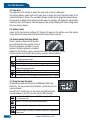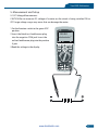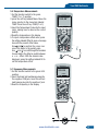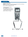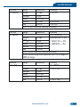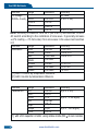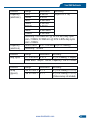
1
TRUE RMS MULTIMETER& OSCILLOSCOPE
AMM-4189
User’s Manual
www.tmatlantic.com
Contents
Contents
True RMS Multimeter.......................................................................................................
1.Introduction...................................................................................................................
2.Safety............................................................................................................................
3.Safety Instructions.........................................................................................................
4.Feature..........................................................................................................................
5.Measurement and Setup................................................................................................
6.General Specifications...................................................................................................
7.Specifications................................................................................................................
5
6
6
7
8
11
30
32
Oscilloscope Section................................................................................................. 37
1.Introduction...................................................................................................................
2.Function and Operation..................................................................................................
3.Examples.......................................................................................................................
4.Fault Processing............................................................................................................
Appendix 1:Daily maintenance..........................................................................................
Appendix 2:Specifications.................................................................................................
40
42
51
52
54
55
Meterbox User’s Guide ........................................................................................... 57
1.Meter Operation.............................................................................................................
2.Meter Connection..........................................................................................................
3.Measurement Mode......................................................................................................
4.Connect Meter Cloud.....................................................................................................
5.Data Recording.............................................................................................................
6.Data Chart....................................................................................................................
7.Data File.......................................................................................................................
8.Data Sharing.................................................................................................................
9.Demo Mode..................................................................................................................
10.Help............................................................................................................................
11.About..........................................................................................................................
www.tmatlantic.com
59
59
61
62
63
64
66
67
67
67
67
True RMS Multimeter
Please read this manual before switching the unit on.
Important safety information inside.
www.cem-instruments.com
www.tmatlantic.com
True RMS Multimeter
1.Introduction
Professional True RMS Industrial D igital Multimeter with oscilloscope functions and TFT
color LCD display,providing fast A/D conver ting sampling time, high accuracy , built-in
datalogging and Trend Capture feactures. It can trace any interrupted problems of the equipments
and watch on without person. It is easy to find and solve the problems of the production
equipments, providing Bluetooth technology and memory the datasheets. It is much more safe
measurements with double molded plastic housing design and IP67 waterprooff unction.
This meter measures AC/DC Voltage, AC/DC Current, Resistan ce,Capacitance,Frequency
(electrical & electronic), Duty Cycle, Diode Test,Insulation Test,and Continuity plus Thermocouple
Temperature. It can store and recall data. It features a waterproof, rugged design for heavy duty
use.Proper use and care of this meter will provide many years of reliable service.
2.Safety
This symbol adjacent to another symbol, terminal or operating device indicates that the
operator must refer to an explanation in the Operating Instructions to avoid personal injury
or damage to the meter.
WARNING This WARNING symbol indicates a potentially hazardous situation, which if not
avoided, could result in death or serious injury.
CAUTION This CAUTION symbol indicates a potentially hazardous situation, which if not
avoided, may result damage to the product.
This symbol advises the user that the terminal(s) so marked must not be connected to a
MAX circuit point at which the voltage with respect to earth ground exceeds (in this case) 1000
VAC or VDC.
This symbol adjacent to one or more ter minals identifies them as being associated with
ranges that may, in normal use, be subjected to particularly hazardous voltages. For
maximum safety, the meter and its test leads should not be handled when these terminals
are energized.
This symbol indicates that a device is protected throughout by double insulation or
reinforced insulation.
PER IEC1010 OVERVOLTAGE INSTALLATION CATEGORY
OVERVOLTAGE CATEGORY I
Equipment of OVERVOLTAGE CATEGORY I is equipment for connection to circuits in which
measures are taken to limit the transient overvoltages to an appropriate low level.
Note – Examples include protected electronic circuits.
6
www.tmatlantic.com
True RMS Multimeter
OVERVOLTAGE CATEGORY II
Equipment of OVERVOLTAGE CATEGORY II is energy-consuming equipment to be supplied
from the fixed installation.
Note – Examples include household, office, and laboratory appliances.
OVERVOLTAGE CATEGORY III
Equipment of OVERVOLTAGE CATEGORY III is equipment in fixed installations.
Note – Examples include switches in the fixed installation and some equipment for industrial
use with permanent connection to the fixed installation.
OVERVOLTAGE CATEGORY IV
Equipment of OVERVOLTAGE CATEGORY IV is for use at the origin of the installation.
Note – Examples include electricity meters and primary over-current protection equipment
3.Safety Instructions
This meter has been designed for safe use, but must be operated with caution.
The rules listed below must be carefully followed for safe operation.
3-1.NEVER apply voltage or current to the meter that exceeds the specified maximum:
Input Protection Limits
Function
Maximum Input
V DC or V AC
1000VDC/AC RMS
mA AC/DC
500mA 1000V fast acting fuse
A AC/DC
10A 1000V fast acting fuse
(20A for 30 seconds max every
15 minutes)
Frequency, Resistance, Capacitance,
1000VDC/AC rms
Duty Cycle, Diode Test, Continuity
Temperature
1000VDC/AC rms
Surge Protection: 8kV peak per IEC 61010
3-2.USE EXTREME CAUTION when working with high voltages.
3-3.DO NOT measure voltage if the voltage on the “COM” input jack exceeds 1000V above
earth ground.
3-4.NEVER connect the meter leads across a voltage source while the function switch is
in the current, resistance, or diode mode. Doing so can damage the meter.
3-5.ALWAYS discharge filter capacitors in power supplies and disconnect the power when
making resistance or diode tests.
3-6.ALWAYS turn off the power and disconnect the test leads before opening the covers to
replace the fuse or batteries.
www.tmatlantic.com
7
True RMS Multimeter
3-7.NEVER operate the meter unless the back cover and the battery and fuse covers are in
place and fastened securely.
If the equipment is used in a manner not specified by the manufacturer, the protection provided
by the equipment may be impaired.
4.Feature
4-1.Understanding the Push Buttons
The 12 push buttons on the front of the Meter
activate features that augment the function
selected using the rotary switch, navigate
menus or control power to Meter circuits.
HELP
RANGE
HOLD
AUTO
MODE
REC
ESC
F1F2F3F4 Selects sub-functions and modes related to the rotary switch function.
Cursor buttons select an item in a menu, adjust display contrast, scroll through information,
and perform data entry.
HOLD Freezes the present reading in the display and allows the display to be saved. Also
accesses AutoHold.
RANGES witches the Meter range mode to manual and then cycles through all ranges. To return
to auto ranging, press the button for 1 second.
MAX/MIN Starts and stops MIN MAX recording.
ESC Return from Power off.
8
www.tmatlantic.com
True RMS Multimeter
4-2.Understanding the Display
5
6
7
Auto Range REL
3
2
0
-5
10
9
-0 . 0 0 0 8 VDC
13:17
4
8
11
03/26/11
VAC
12
0 . 0005
13
-4
-3
-2
-1
0
1
2
3
4
14
5VAC
- 23.2 dBm
1
MENU
SAVE
REL,%
15
SETUP
1.Soft key labels Indicates the function of the button just below the displayed label.
2.Bar graph Analog display of the input signal(See the "Bar Graph" section for more information).
3.Minus sign Indicates a negative reading.
4.Indicates the range the Meter is in and the ranging mode (auto or manual)
5.Battery level Indicates the charge level batteries.
6.Time Indicates the time set in the internal clock.
7.Mode annunciators Indicates the Meter's mode.
8.Minimeasurement Displays the lightning bolt (when necessary) and the input value when the
primary and secondary displays are covered by a menu or pop-up message.
9.Main display Displays measurement information about the input signal.
10.Date Indicates the date set in the internal clock.
11.Beeper Indicates the Meter’s beeper is enabled (not associated with the continuity beeper).
12.Units Indicates the units of measure.
N Auxiliary Units Indicates unit less measurements like Crest Factor.
13.Blue tooth Indicates activity over the communication link.
14.Relative Indicates the displayed value is relative to a reference value.
15.Secondary display Displays secondary measurement information about the input signal.
4-3.Bar Graph
The analog bar graph functions like the needle on an analog meter, but without the overshoot.
For frequency, duty cycle, pulse width, dBm, and crest factor functions, the bar graph
represents the amplitude of the input signal (volts or amps) and not the value in the primary
display. The bar graph is not shown for capacitance, temperature, AC+DC, AC over DC, peak,
or min max functions. For DC voltage, DC current, and all relative percent modes, a zerocentered bar graph is displayed. For DC voltage and current, the bar graph range is the
maximum of the selected range. For relative percent mode, the bar graph goes to ±10 %. The
number of lit segments indicates the measured value and is relative to the full-scale value of
the selected range. In the 50 VAC range, for example, the major divisions on the scale represent
0, 5, 10, 15, 20, 25, 30, 35, 40, 45, and 50 VAC. An input of 25 VAC turns on segments up
to the middle of the scale.
www.tmatlantic.com
9
True RMS Multimeter
4-4.Page Area
The page area of the display is where the main meter content is displayed.
The primary display (upper half of the page area) is where the most important value of the
selected function is shown. The secondary display contains the bar graph and values that may
be measured in addition to the primary function value. For example, with frequency measurement
selected in Vac, the frequency value will appear in the primary display with the ac voltage value
in the secondary display.
4-5.Softkey Labels
Labels for the four function softkeys (F1 through F4) appear in the bottom row of the display.
These labels will change based on the function and/or menu selection.
4-6.Understanding the Rotary Switch
Select a primary measurement function
10A
by positioning the rotary switch to one of
mA
the icons around its perimeter. For each
μA
function, the Meter presents a standard
display for that function (range, measurement units, and modifiers). Button
choices made in one function do not carry over into another function.
OSC
V
Hz%
mV
Temp
Hz%
Ω
CAP
DC(AC) and AC+DC voltage measurements
AC voltage measurements
DC(AC) millivolts, ac+dc millivolt measurements
Frequency measurements
Resistance, Diode test, Capacitance and Continuity measurements
Temperature measurements
AC, DC and AC+DC amps measurements
AC, DC and AC+DC milliamps measurements
AC, DC and AC+DC microampere measurements up to 5,000μA
4-7.Using the Input Terminals
All functions except current use the VOHMSand COM input
terminals. The two current input terminals (A and mA/μA) are
Used as follows:
Current from 0 to 500 mA, use the uAmA and COM terminals.
Current between 0 and 10 A use the A and COM terminals.
Input for 0 A to 10.00 A current (20VA overload for 30 seconds
on, 10 minutes off),
Input for 0 A to 500 mA current measurements.
Return terminal for all measurements.
Input for voltage, continuity, resistance, diode test, conductance,
capacitance.
10
www.tmatlantic.com
VΩ
CAP
Temp Hz%
CAT III 600V
True RMS Multimeter
5. Measurement and Setup
5-1.DC Voltage Measurements
CAUTION: Do not measure DC voltages if a motor on the circuit is being switched ON or
OFF. Large voltage surges may occur that can damage the meter.
1. Set the function switch to the green VDC
position.
2.Insert the black test lead banana plug
into the negative COM jack. Insert the
red test lead banana plug into the positive
V jack.
3.Read the voltage in the display.
DT-9989
06/13/07
8:10pm
DXWR UDQJH
9'&
100.00
F1
F2
9'&
F3
F4
HELP
HOLD
RANGE
AUTO
HOLD
MAX
MIN
ESC
MODE
OSC
10A
mA
V
REC
Hz%
mV
Temp
Hz%
A
CAP
Bluetooth
V
CAP
Temp Hz%
CAT III 600V
www.tmatlantic.com
11
True RMS Multimeter
5-2.AC Voltage Measurements
WARNING: Risk of Electrocution. The probe tips may not be long enough to contact the live
parts inside some 240V outlets for appliances because the contacts are recessed deep in the
outlets. As a result, the reading may show 0 volts when the outlet actually has voltage on it.
Make sure the probe tips are touching the metal contacts inside the outlet before assuming
that no voltage is present.
CAUTION: Do not measure AC voltages if a motor on the circuit is being switched ON or
OFF. Large voltage surges may occur that can damage the meter.
1.Set the function switch to the green VAC
position.
2.press the soft key labeled Menu. Move the
menu selector to the menu item labeled VAC.
Press the soft key VAC
3.Insert the black test lead banana plug into
the negative COM jack. Insert red test lead
banana plug into the positive V jack.
4.Read the voltage in the main display
DT-9989
8:10pm
06/13/07
auto range
0
VAC
100.00
100
F1
200
F2
300
400
500 VAC
F3
F4
HELP
HOLD
RANGE
HOLD
AUTO
MAX
MIN
ESC
MODE
OSC
10A
mA
V
REC
Hz%
mV
Temp
Hz%
Ω
μA
CAP
Bluetooth
VΩ
CAP
Temp Hz%
CAT III 600V
12
www.tmatlantic.com
True RMS Multimeter
5-3.Making dB Measurements
The Meter is capable of displaying voltage as a dB value, either relative to 1 milliwatt (dBm),
a reference voltage of 1 volt (dBV) or a user-selectable reference value.
1.Set the function switch to the green VAC
position.
2.press the softkey labeled Menu. Move the
menu selector to the menu item labeled
dBm. Press the softkey dBm
3.Insert the black test lead banana plug into
the negative COM jack. Insert red test lead
banana plug into the positive V jack.
4.Read the voltage in the main display and the dBm in the Secondary display
5.To select another reference value, press the softkey labeled Ref to display a message box
with the current reference value. Pressing
or
, scrolls through the nine predefined
references: 4,8,16,25,32,50,75,600 and 1000. Set the reference by pressing the softkey labeled
OK.
5-4.Low Pass Filter
The Meter is equipped with an ac low pass
filter. When measuring ac voltage, press the
soft key labeled Menu to open the function
menu, and move the menu selector to the LO
item. Next, press the softkey labeled LO to
toggle the low pass filter mode .
www.tmatlantic.com
13
True RMS Multimeter
5-5.mV Voltage Measurements
CAUTION: Do not measure mV voltages if a motor on the circuit is being switched ON or
OFF. Large voltage surges may occur that can damage the meter.
1.Set the function switch to the green mV
position.
2.Press the soft key labeled Menu.
Move the menu selector to the menu item
labeled mVDC(mVAC). Press the soft key
mVDC(mVAC).
3.Insert the black test lead banana plug into
the negative COM jack. Insert the red test
lead banana plug into the positive V jack.
4.Read the mV voltage in the display
DT-9989
8:10pm
06/13/07
auto range
0
mVAC
500.00
100
F1
200
F2
300
400
500 mVAC
F3
F4
HELP
HOLD
RANGE
HOLD
AUTO
MAX
MIN
ESC
MODE
OSC
10A
mA
V
REC
Hz%
mV
Temp
Hz%
Ω
μA
CAP
Bluetooth
VΩ
CAP
Temp Hz%
CAT III 600V
14
www.tmatlantic.com
True RMS Multimeter
5-6.Temperature Measurements
1.Set the function switch to the green
TEMP(°C or °F) position.
2.press the soft key labeled Menu. Move the
menu selector to the menu item labeled
TEMP. Press the soft key TEMP(C or F).
3.Insert the Temperature Probe into the input
jacks, making sure to observe the correct
polarity.
4.Read the temperature in the display
5.To input a temperature offset value, press
the softkey labeled Offset to open a message
box with the present offset value.
Use and to position the cursor over
one of the digits or the polarity sign.
Use and to scroll through the numbers
for each digit in the offset or switch between
a + or – offset. With the desired value
displayed, press the softkey labeled OK to
set the temperature offset.
DT-9989
8:10pm
06/13/07
auto range
°C
100.00
F1
F3
F2
F4
HELP
HOLD
RANGE
AUTO
HOLD
MAX
MIN
ESC
MODE
V
OSC
REC
Hz%
mV
10A
Temp
Hz%
mA
Ω
μA
CAP
Bluetooth
VΩ
CAP
Temp Hz%
CAT III 600V
DT-9989
8:10pm
5-7.Frequency Measurements
1.Set the function switch to the green Hz%
position.
2.Insert the black test lead banana plug into
the negative COM jack. Insert the red test
lead banana plug into the positive V jack.
3.Read the Frequency in the display
06/13/07
auto range
Hz
50.000
0.00%
F1
F2
F3
F4
HELP
HOLD
RANGE
AUTO
HOLD
MAX
MIN
ESC
MODE
OSC
10A
mA
V
REC
Hz%
mV
Temp
Hz%
Ω
μA
CAP
Bluetooth
VΩ
CAP
Temp Hz%
CAT III 600V
www.tmatlantic.com
15
True RMS Multimeter
5-8.Resistance Measurements
WARNING: To avoid electric shock, disconnect power to the unit under test and discharge
all capacitors before taking any resistance measurements.
Remove the batteries and unplug the line cords.
1.Set the function switch to the green
Ω CAP
position.
2.Insert the black test lead banana plug into
the negative COM jack. Insert the red test
lead banana plug into the positive Ω Jack.
3.Read the resistance in the display.
DT-9989
8:10pm
06/13/07
auto range
50.000
F1
F2
MΩ
F3
F4
HELP
HOLD
RANGE
HOLD
AUTO
MAX
MIN
ESC
MODE
OSC
10A
mA
V
REC
Hz%
mV
Temp
Hz%
Ω
μA
CAP
Bluetooth
VΩ
CAP
Temp Hz%
CAT III 600V
16
www.tmatlantic.com
True RMS Multimeter
5-9.Continuity Check
WARNING: To avoid electric shock, disconnect power to the unit under test and discharge all
capacitors before taking any resistance measurements. Remove the batteries and unplug
the line cords.
1.Set the function switch to the green
Ω CAP
position.
2.Press the soft key labeled Menu. Move the
menu selector to the menu item labeled
Beeper. Press the soft key Beeper.
3.Insert the black test lead banana plug into
the negative COM jack. Insert the red test
lead banana plug into the positive jack.
4.If the resistance is less than approximately
25Ω, the audible signal will sound. If the
circuit is open, the display will indicate “OL”.
DT-9989
8:10pm
06/13/07
auto range
25.000
F1
F2
Ω
F3
F4
HELP
HOLD
RANGE
HOLD
AUTO
MAX
MIN
ESC
MODE
OSC
10A
mA
V
REC
Hz%
mV
Temp
Hz%
Ω
μA
CAP
Bluetooth
VΩ
CAP
Temp Hz%
CAT III 600V
www.tmatlantic.com
17
True RMS Multimeter
5-10.Diode Test
1.Set the function switch to the green
Ω CAP
position.
2.Press the soft key labeled Menu. Move the
menu selector to the menu item labeled
Diode. Press the soft key Diode.
3.Insert the black test lead banana plug into
the negative COM jack and the red test
lead banana plug into the positive V jack.
5.Forward voltage will typically indicate
0.400 to 3.200V. Reverse voltage will
indicate “OL”. Shorted devices will indicate
near 0V and an open device will indicate
“OL” in both polarities.
DT-9989
8:10pm
06/13/07
auto range
V
0.400
F1
F2
F3
F4
HELP
HOLD
RANGE
HOLD
AUTO
MAX
MIN
ESC
MODE
OSC
10A
mA
V
REC
Hz%
mV
Temp
Hz%
Ω
μA
CAP
Bluetooth
VΩ
CAP
Temp Hz%
CAT III 600V
18
www.tmatlantic.com
True RMS Multimeter
5-11.Capacitance Measurements
WARNING: To avoid electric shock, disconnect power to the unit under test and discharge all
capacitors before taking any capacitance measurements. Remove the batteries and unplug
the line cords.
1.Set the rotary function switch to the green
Ω CAP
position.
2.Press the soft key labeled Menu. Move the
menu selector to the menu item labeled
Cap. Press the soft key Cap.
3.Insert the black test lead banana plug into
the negative COM jack. Insert the red test
lead banana plug into the positive V jack.
4.Read the capacitance value in the Display
DT-9989
8:10pm
06/13/07
auto range
mF
10.00
F1
F2
F3
F4
HELP
HOLD
RANGE
HOLD
AUTO
MAX
MIN
ESC
MODE
OSC
10A
mA
V
REC
Hz%
mV
Temp
Hz%
Ω
μA
CAP
Bluetooth
VΩ
CAP
Temp Hz%
CAT III 600V
www.tmatlantic.com
19
True RMS Multimeter
5-12.DC Current Measurements
CAUTION: Do not make 20A current measurements for longer than 30 seconds. Exceeding
30 seconds may cause damage to the meter and/or the test leads.
1.Insert the black test lead banana plug into
the negative COM jack.
2.For current measurements up to 5000μA DC,
set the function switch to the yellow μA
position and insert the red test lead banana
plug into the μA/mA jack.
3.For current measurements up to500mA DC,
set the function switch to the yellow mA
position and insert the red test lead banana
plug into the μA/mA jack.
4.For current measurements up to 10A DC,
set the function switch to the yellow 10A
position and insert the red test lead banana
plug into the 10A jack.
5.Press the MODE button to indicate “DC”
on the display.
6.Read the current in the display.
20
DT-9989
8:10pm
06/13/07
auto range
0
ADC
10.000
100
F1
200
F2
300
400
500 ADC
F3
F4
HELP
HOLD
RANGE
AUTO
HOLD
MAX
MIN
ESC
MODE
OSC
10A
mA
V
REC
Hz%
mV
Temp
Hz%
Ω
μA
www.tmatlantic.com
CAP
Bluetooth
VΩ
CAP
Temp Hz%
CAT III 600V
True RMS Multimeter
5-13.AC Current Measurements
CAUTION: Do not make 10A current measurements for longer than 30 seconds. Exceeding
30 seconds may cause damage to the meter and/or the test leads.
1.Insert the black test lead banana plug into
the negative COM jack.
2.For current measurements up to 5000μA AC,
set the function switch to the yellow μA
position and insert the red test lead banana
plug into the μA/mA jack.
3.For current measurements up to 500mA AC,
set the function switch to the yellow mA
position and insert the red test lead banana
plug into the μA/mA jack.
4.For current measurements up to 20A AC,
set the function switch to the yellow 10A
position and insert the red test lead banana
plug into the 10A jack.
5.Press the soft key labeled Menu. Move the
menu selector to the menu item labeled AC.
Press the soft key AC.
6.Read the current in the display
DT-9989
8:10pm
06/13/07
auto range
0
www.tmatlantic.com
AAC
10.000
100
F1
200
F2
300
400
500 AAC
F3
F4
HELP
HOLD
RANGE
HOLD
AUTO
MAX
MIN
ESC
MODE
OSC
10A
mA
V
REC
Hz%
mV
Temp
Hz%
Ω
μA
CAP
Bluetooth
VΩ
CAP
Temp Hz%
CAT III 600V
21
True RMS Multimeter
5-14.Understanding Function Menus
Each primary measurement function (rotary switch position) has a number of optional
sub-functions or modes accessed by pressing the softkey labeled Menu (F1). A typical menu
is shown in Figure.
Menu selection is indicated by the filled-in
black square(hereafter the menu selector)
to the left of a menu item. Use the four
front-panel cursor buttons (
) to
position the menu selector next to a menu
item. As the menu selector moves between
menu items, the four softkeys and their labels
change to reflect the available functions
and/or modes available for the selection
menu item.
5-15.Using Help
While operating the Meter, more information about a selected function, a front-panel button,
or a menu item may be necessary. Press soft key HELP to open an information window that
lists topics covering the functions and modifiers that are available at the time the button is
pressed. Each topic provides a brief explanation on a Meter function or feature. The number
of information topics displayed at any one time may exceed the display area. Use the softkeys
labeled Next and Prev to move from topic to topic. Use the softkey labeled More or and
to scroll through the information a full screen at a time.
22
www.tmatlantic.com
True RMS Multimeter
5-16.Measuring AC and DC Signals
The Meter is capable of displaying both AC and DC signal components (voltage or current)
as two separate readings or one AC+DC(RMS) value combined. As shown in Figure , the
Meter displays ac and dc combinations two ways: DC displayed over AC (DC,AC), and AC
combined with dc (AC+DC). Select one of these three displays using the Function and Mode
menu. With the rotary switch set to V, mV, A, mA,or uA, press the soft key labeled Menu.
Move the menu selector to the menu item labeled AC+DC. At this point, three different soft key
labels indicate AC+DC (F1),and DC,AC (F2). Press the soft key that presents these two
signals as needed. While in any of the three AC+DC modes, peak measurements, frequency,
duty cycle, relative %, and period measurements are not allowed. In addition to these modes,
MIN MAX, relative.
5-17.Capturing Minimum and Maximum Values
The MAX MIN Record mode captures minimum, average, and maximum input values. When the
input goes below the recorded minimum value or above the recorded maximum value, the
Meter beeps and records the new value. The Meter stores the elapsed time since the recording
session was started at the same time. The MAX MIN mode also calculates an average of all
readings taken since the MAX MIN mode was activated. This mode is for capturing intermittent
readings,recording minimum and maximum readings unattended, or recording readings while
equipment operation precludes watching the Meter. The MIN MAX mode is best for recording
power supply surges, inrush currents, and finding intermittent failures. Response time is the
length of time an input must stayat a new value to be captured as a possible new minimumor
maximum value.
To activate the MAX MIN mode, press MAX MIN. As shown in Figure, the Meter displays e
at the top of the measurement page, and the MAX MIN start date and time along the bottom of the
page. In addition, the recorded maximum, average, and minimum values appear in the secondary
display with their respective elapsed times.
To stop a MIN MAX recording session, press
the softkey labeled Stop. The summary
information in the display freezes, and the
softkeys change function to allow saving
the collected data. Pressing the softkey
labeled Close exits the MIN MAX record
session without saving the collected data.
www.tmatlantic.com
23
True RMS Multimeter
To save the MIN MAX screen data, the MIN MAX session must be ended by pressing the
softkey labeled Stop. Next, press the softkey labeled Save.A dialog box openswhere the
default saved name can be selected or anothername assigned. the softkey labeled Save to
store. Pressing the softkey labeled Restart while MIN MAX is running stops the MIN MAX
session, discards all MIN MAXdata, and immediately starts a new MIN MAX recording session.
5-18.Capturing Peak Values
To activate the peak mode, press the softkey
labeled Menu.Move the menu selector next
to the menu item labeledPeak, CF or Peak.
Press the softkey labeled Peak to startthe
peak recording session.
5-19.Relative Values
To activate the peak mode, press the softkey labeled Menu. Move the menu selector next to the
menu item labeled REL or Peak. Press the softkey labeled REL to start the peak recording session.
If the Meter is already in the relative function, pressing Rel% causes the Meter to turn off relative
and display relative percent.
5-20.Low Pass Filter
The Meter is equipped with an ac low pass
filter. When measuring AC voltage, press the
softkey labeled Menu to open the function
menu, and move the menu selector to the
LO item. Next, press the softkey labeled LO
to toggle the low pass filter mode.
03/26/11
13:25
5-21.Hold and AutoHold Mode
Auto Range
Hold
To freeze the display for any function, press
key HOLD.
Pressing the softkey labeled AutoHOLD
activates AutoHold if the Meter is not in the
AUTOHOLD
SAVE
SETUP
Peak, MIN MAX, or Record modes. AutoHold
operation monitors the input signal and updates the display and, if enabled, sounds the beeper,
whenever a new stable measurement is detected. A stable measurement is one that does not
vary more than a selected adjustable percentage (AutoHold threshold) for at least one second.
The Meter filtersout open lead conditions so the Meter leads can be moved between test
points without triggering a display update.
0 000
-50 -40 -30 -20 -10
24
www.tmatlantic.com
0
10
20
30
40 50mADC
True RMS Multimeter
5-22.Storing Individual Measurement Data
For all measurement functions, a snapshot
of the screen data is saved by pressing the
softkey labeled Save.
Edit name, then pressing the softkey labeled
Save stored date.
5-23.Viewing Memory Data
Viewing data stored in the Meter’s memory is performed through the save menu. Press the
softkey labeled Save. Position the menu selector next to the menu item labeled View measure
and press the softkey labeled View.
If there are previously stored records, press the softkey labeled Prev to page back through
previously stored records. Press the softkey labeled Next to page in the other direction. press the
softkey labeled Delete to delete stored records. Press Close to return to normal Meter operation.
5-24.Viewing Trend Data
Viewing data stored in the Meter’s memory
is performed through the save menu. Press
the softkey labeled Save. Position the menu
selector next to the menu item labeled View
record and press the softkey labeled View.
If there are previously stored records, press
the softkey labeled Prev to page back through
previously stored records. Press the softkey labeled Next to page in the other direction.Press
Close to return to normal Meter operation.
13:22
Press the soft key labeled Trend to display
the recorded data in a trend-plot view.
Press the softkey labeled Delete recorded data
15
9.0
3.0
0
3.0
9.0
15
00:00
03/26/11
VDC
00:15
DELETE
www.tmatlantic.com
03/26/11 13:20:53
00:30
00:45
01:00
0.0003 vdc 13:21:14
CLOSE
SUMMARY
25
True RMS Multimeter
5-25.Recording Measurement Data
The Meter’s record feature collects measurement information over a user-specified duration.
This collection of information is called a recording session. A recording session is made up
of one or more measurement records Each record contains measurement summary information
covering the duration of the record.
Press the softkey labeled Save. Position the
menu selector next to the menu item labeled
Record and press the softkey labeled Record
to open the configuration display.
Recording session duration,and sample interval duration.Both variables affect the recording
length and number of intervals recorded. These two variables may interact, in that setting one
variable may adjust the other variable to fit the recording session within the available memory.
The percentage of memory available at the beginning of a recording session is displayed below
the duration and sample interval settings.
To change either of the two recording variables, use the cursor buttons to position the menu
selector next to the desired menu item and press the softkey labeled Edit. Use
and
to move between and set each digit of the selected variable.
Press the softkey labeled Start to start records.
The recording session will continue until the allocated memory is used, the batteries expire,
the rotary switch is moved. or the session is terminated by pressing the softkey labeled Stop.
5.26.Zooming in on Trend Data
28
While viewing trend data, pressing or zooms in or out respectively on the data around the
cursor. Each press of reduces the x-axis time period by one half to reveal more details. Each
press of doubles the time period until all the recorded data is displayed. The zoom level is
displayed in the upper-right hand corner of the display.
26
www.tmatlantic.com
True RMS Multimeter
5-27.Changing Meter Setup Options
The Meter has a number of preset features such as date and time formats and battery save mode
timeouts, and the displayed language. These variables are referred to as Meter setup options.
Many setup options affect general Meter operations and are active in all functions. Others are
limited toone function or group of functions.
Access to the setup options is always available through the
softkey labeled Setup. Information about the Meter, such as
serial number, model, for example. is also accessed
through the setup menu.
5-28.Resetting Meter Setup Options
The Meter’s setup options can be reset to default values through the setup menu. Open the
setup menu by pressing the softkey labeled Setup. Position the menu selector next to the menu
item labeled Reset and press the softkey labeled Setup. A message will appear asking to
confirm the reset action. Press the softkey labeled OK to perform the reset.
5-29.Meter Info
The Meter Info selection lists the serial number, model number, firmware version, calibration
date, and calibration counter. Operator name, company name are displayed.
5-30.Setting the Event Threshold Value
Press the softkey labeled Setup to access the setup menu.
Using the cursor buttons, move the menu selector next to the menu item labeled Instrument
and press the softkey labeled Enter to open the recording setup screen. Using the cursor
buttons,move the menu selector next to the menu item labeled Event Threshold for Recording
(AutoHOLD) and then press the softkey labeled Edit. Press or to scroll through the event
threshold values. With the desired value selected, press the softkey labeled Close.
5-31.Calibration
The Calibration selection allows a qualified calibration technician to enter a
password that allows the Meter to be calibrated.
Press the softkey labeled Setup to access the setup menu. Using the cursor
buttons, move the menu selector next to the menu item labeled Calibration and
press the softkey labeled Calibrate, Then input password ,Enter Calibration menu.
If change password, Press the softkey labeled Setup to access the setup menu.
Using the cursor buttons, move the menu selector next to the menu item labeled
Calibration and press the softkey labeled password, Then input current password,
Then input new password.
www.tmatlantic.com
27
True RMS Multimeter
5-32.Using Communications
You can use the Wireless communication link and transfer the contents of a meter’s memory
to a PC.
Press the softkey labeled Setup to access the setup menu. Using the cursor buttons, move the
menu selector next to the menu item labeled communicate and press the softkey labeled PC.
press the softkey labeled open will start communications function; or press the softkey labeled
close will close communications function..
5-33.Setting Date and Time
The Meter’s internal clock is used in the display and for timestamping recorded measurements.
To change the date and time as well as the display format, press the softkey labeled Setup.
Position the menu selector next to the menu item labeled Display. To set the date and time,
press the softkey labeled Date/Time to open the date/time menu. Next, position the menu
selector next to either the Set Date item or Set Time item and press the softkey labeled Edit.
Using and , position the cursor on the date or time element to adjust.Use and to
change the selected date or time element value. Press OK to complete the action.
5-34.Auto Power Off
Press the softkey labeled Setup. Position the menu selector next to the menu item labeled
Display. To set Auto Power Off and then press the softkey labeledEdit. Use and to adjust
the time to one of the preset values. 0 is disable the timeout feature. Press the softkey labeled
OK to set the selected time. Press the softkey labeled Close to return.
5-35.Setting Format
Press the softkey labeled Setup. Position the menu selector next to the menu item labeled
Format. Using thecursor buttons, move the menu selector next to the menuitem labeled
Numeric(Date\Time) format, press the softkey labeled EDIT, select 0.0000(0,0000) and MM/
DD/YY(DD/MM/YY) and 24 HOUR (12 HOUR) format.
5-36.Replacing the Batteries
Refer to Figure and replace the batteries as follows:
1.Turn the Meter off and remove the test leads from the terminals.
2.Remove the battery door assembly by using a standardblade screwdriver to turn the battery
door screw one-half turn counterclockwise.
3.Replace the batteries with 7.4 volt charge batteries Observe proper polarity.
4.Reinstall the battery door assembly and secure it by turning the screw one-half turn
clockwise.
28
www.tmatlantic.com
True RMS Multimeter
5-37.Replacing the Fuses
Referring to Figure , examine or replace the Meter's fuses as follows:
1.Turn the Meter off and remove the test leads from the terminals.
2.Remove the battery door assembly by using a standardblade screwdriver to turn the battery
door screw one-half turn counterclockwise.
3.Remove the fuse by gently prying one end loose, then sliding the fuse out
of its bracket.
4.Install only specified replacement fuses.
5.Reinstall the battery door assembly and secure it by turning the screw
one-half turn clockwise
Stand
battery cover
7.4V Li-ion battery
battery cover
7.4V Li-ion
battery
Seal ring of
battery cover
Back shell
Stand
Seal ring of
battery cover
Fuse wire
Seal ring of
back Shell
Fuse wire
Fuse wire
www.tmatlantic.com
29
True RMS Multimeter
6.General Specification
Enclosure
Shock (Drop Test)
Diode Test
Double molded, waterproof
6.5 feet (2 meters)
Test current of 0.9mA maximum, open circuit
voltage 3.2V DC typical
Continuity Check
Audible signal will sound if the resistance is less
than 25Ω (approx.), test current <0.35mA
PEAK
Captures peaks >1ms
Temperature Sensor
Requires type K thermocouple
Input Impedance
>10MΩ VDC & >9MΩ VAC
AC Response
True RMS
AC True RMS
The term stands for “Root-Mean-Square” which
represents the method of calculation of the voltage
or current value. Average responding multimeters
are calibrated to read correctly only on sine waves
and they will read inaccurately on non-sine wave
or distorted signals. True rms meters read
accurately on either type of signal.
ACV Bandwidth
50Hz to 100000Hz
<3 at full scale up to 500V, decreasing linearly
Crest Factor
to <1.5 at 1000V
Display
50,000 count backlit liquid crystal with bargraph
Overrange indication
“OL” is displayed
Auto Power Off
5-30minutes (approximately) with disable feature
Polarity
Automatic (no indication for positive); Minus (-)
sign for negative
Measurement Rate
20 times per second
Low Battery Indication “ ” is displayed if battery voltage drops below
operating voltage
Battery
One7.4V
30
www.tmatlantic.com
True RMS Multimeter
Fuses
Operating Temperatur
Storage Temperature
Operating Humidity
Storage Humidity
Operating Altitude
Safety
mA, μA ranges; 0.5A/1000V ceramic fast blow
A range; 10A/1000V ceramic fast blow
5°C to 40°C (41°F to 104°F)
-20°C to 60°C (-4°F to 140°F)
Max 80% up to 31°C (87°F) decreasing linearly
to 50% at 40°C (104°F)
<80%
7000ft. (2000meters) maximum.
This meter is intended for origin of installation use
and protected, against the users, by double
insulation per EN61010-1 and IEC61010-1 2nd
Edition (2001)to Category IV 600V and Category
III 1000V; Pollution Degree 2. The meter also meets
UL 61010-1, 2nd Edition (2004), CAN/CSA C22.2
No. 61010-1 2nd Edition (2004),and UL 61010B
-2-031, 1st Edition (2003)
www.tmatlantic.com
31
True RMS Multimeter
7.Specifications
Function
Range
Resolution
[1]
DC Voltage
0.001mV
50mV
0.01mV
500mV [2]
0.0001V
5V
0.001V
50V
0.01V
500V
0.1V
1000V
[1] Add 10 counts by temperature influence.
[2] Add 4 counts by temperature influence.
Function
AC Voltage
Range
Resolution
Accuracy
(0.05% + 20)
(0.025% + 5digits)
(0.025% + 5digits)
(0.025% + 5digits)
(0.05% + 5digits)
(0.1% + 5)
Accuracy
50 to 10000Hz
50/60Hz(0.3% + 25)
<1KHz(0.5% + 25)
<5KHz(3% + 25)
50mV
0.001mV
500mV
0.01mV
5V
0.0001V
50V
0.001V
500V
0.01V
1000V
0.1V
All AC voltage ranges are specified from 5% of range to
100% of range
Function
(AC+DC)
Range
Resolution
50mV
500mV
5V
50V
500V
1000V
0.001mV
0.01mV
0.0001V [1]
0.001V
0.01V
0.1V
[1] Add 1% above 5k
32
www.tmatlantic.com
Accuracy
0 to 1000Hz
<1KHZ(1% + 25)
<10KHZ(3.5% + 25)
True RMS Multimeter
Function
DC Current
Range
Resolution
Accuracy
500μA
0.01μA
0.1%+20
5000μA
0.1μA
50mA
0.001mA
500mA
0.01mA
0.15%+20
10A
0.001A
0.3%+20
(20A: 30 sec max with reduced accuracy)
Function
AC Current
Range
Resolution
Accuracy
50 to 10000Hz
50/60Hz(0.6% + 25)
<1KHz(1.5% + 25)
<10KHz(3% + 25)
500μA
0.01μA
5000μA
0.1μA
50mA
0.001mA
500mA
0.01mA
10A
0.001A
(20A: 30 sec max with reduced accuracy)
All AC current ranges are specified from 5% of range to
100% of range
Function
(AC+DC)
Range
Resolution
500μA
5000μA
50mA
500mA
10A
0.01μA
0.1μA
0.001mA
0.01mA
0.001A
www.tmatlantic.com
Accuracy
0 to 1000Hz
(1.0% + 25)
(1.5% + 40)
33
True RMS Multimeter
Function
Range
Resolution
Accuracy
AC Voltage
5K-100K
(5000+Count) 50mV
0.001mV
(5.0% + 40)
500mV
0.01mV
5V
0.0001V
50V
0.001V
(6.0% + 40)
NOTE: Accuracy is stated at 18 to 28°C (65 to 83°F) and less than 75%RH.
AC switch according to the calibration of sine wave. It generally increase
±(2% reading + 2% full scale) if non sine wave in the wave crest less than
3.0.
Function
Range
Resolution
Accuracy
Resistance
0.001Ω
0.5%+20
50Ω[1]
0.01Ω
0.05%+10
500Ω[2]
0.0001kΩ
0.05%+10
5kΩ
0.001kΩ
50kΩ
0.01kΩ
0.1%+10
500kΩ
0.001MΩ
0.2%+20
5MΩ
0.001MΩ
2%+20
50MΩ
[1] Add 10 counts by temperature influence.
[2] Add 4 counts by temperature influence.
Function
Capacitance
Range
5nF[1]
50nF[1]
500nF
5μF
50μF
500μF
10mF
Resolution
0.001nF
0.01nF
0.1nF
0.001μF
0.01μF
0.1μF
0.01mF
Accuracy
±(2% + 40)
±(2% + 40 digits)
±(5% +40 digits)
[1] with a film capacitor or better ,using relatiue mode (REL ) to zero residual.
34
www.tmatlantic.com
True RMS Multimeter
Function
Frequency
(electronic)
Frequency
(electrical)
Range
Resolution
Accuracy
50Hz
0.001Hz
±(0.01% + 10)
500Hz
0.01Hz
5kHz
0.0001kHz
50kHz
0.001kHz
500kHz
0.01kHz
5MHz
0.0001MHz
10MHz
0.001MHz
Sensitivity: 0.8V RMS min. @ 20% to 80% duty cycle
and <100kHz; 5V RMS min @ 20% to 80% duty cycle
and >100kHz.
40.00-10kHz 0.01 - 0.001kHz ±(0.5% reading)
Sensitivity: 1V RMS
Function
Duty Cycle
Range
Resolution Accuracy
0.1 to 99.90% 0.01%
±(1.2% reading + 2digits)
Pulse width: 100μs - 100ms, Frequency: 5Hz to 150kHz
Function
Temp
(type-K)
Range
Resolution
-50 to 1000°C 0.1°C
-58 to 1832°F 0.1°F
Accuracy
±(1.0% reading + 2.5°C)
±(1.0% reading + 4.5°F)
(Probe accuracy not included)
www.tmatlantic.com
35
Oscilloscope Section
Please read this manual before switching the unit on.
Important safety information inside.
www.cem-instruments.com
www.tmatlantic.com
Oscilloscope Section
Introduction
Digital Oscilloscope, is of compact size, powerful and easily operated; TFT color LCD display,
realizing its ease of use which can greatly improve customer’s work efficiency.
Digital Oscilloscope performs outstandingly, powerful, affordable, with a high cost performance.
Its real time sample rate is up to 50 MSa/s, can meet the market needs of high capture speed,
complicated signal; supports internal storage and Bluetooth data transmission, customer can
take repeated measurements and prints of the data graph by upper computer.
This meter measures AC/DC Voltage, AC/DC Current, Resistance, Capacitance, Frequency
(electrical & electronic), Duty Cycle, Diode Test, Insulation Test, and Continuity plus Thermocouple
Temperature. It can store and recall data. It features a waterproof, rugged design for heavy duty
use. Proper use and care of this meter will provide many years of reliable service.
Features
•Brand new design, compact size, simple portability
•TFT color LCD display, waveform display much more clear and stable
•Real time sample rate: 500Sps—50 Msa/s
• Storage depth: 3Kpts
•Trigger function: rising edge, falling edge
•Waveform record
•Auto search
•10 set waveform storage/output; waveform data can be transmitted by Bluetooth or wireless
USB interface to upper computer for further operation
•Cursor test
•Multi-screen display for channel waveform and FFT waveform
•Menu display mode, much flexible and natural operation for customer
•English online help system
•A user manual
•Product warranty card
•Certificate of quality
•One set of 1:1 probe
•One adaptor
•A charger according with user’s country standard
•CD ( pc software)
38
www.tmatlantic.com
Oscilloscope Section
General safety requirements
Know about the following safety precautions to avoid personal injury, also to prevent damage
generated by connection of this product with any other product. In order to avoid any potential
danger, please use the product according to the regulation.
Only qualified technical personnel can take the maintenance procedures.
Prevent fire disaster or personal injury.
Use proper charger. Only special charger for this product confirmed by user’s country is
available.
Insert and pull out correctly. Don’t insert or pull out while test wire is connecting with power
cable.
Connect the probe correctly. Probe ground wire is the same as earth potential; please don’t
connect the ground wire to a high voltage. During the test procedure, please don’t touch bare
contacts or components.
Check all the terminal ratings. In order to prevent danger of fire and electrical shock, please
check all the ratings and notes of this product.
Before connecting the device, please read the user manual for further information of concerned
ratings.
Don’t operate with the cover opened. If the cover-plate or face-plate is removed, please don’t
use the device.
Use proper fuse wire. Only the fuse wires which compliances with specified type and ratings
of this product can be adopted.
Don’t operate while suspecting product malfunction. If suspect any damage of this device,
please inform qualified maintenance personnel to examine.
Avoid circuit exposure. Don’t touch any bare contact or component after connection of industrial
frequency power.
Please don’t operate under an inflammable or explosive circumstance.
Keep device surface clean and dry.
www.tmatlantic.com
39
Oscilloscope Section
Summary
The manual introduces operation information of Digital Oscilloscope which includes the
following chapters:
•"Introduction"presents the front panel, user interface, function check and probe of the
oscilloscope.
•"Function introduction and operation" makes a detailed introduction of oscilloscope function
and operation.
•"Application example: includes many examples of testing, for readers’ reference.
•"Appendix 1: daily maintenance and cleaning" briefly presents how to maintain the
oscilloscope.
•"Appendix 2: specifications" details the specifications of Digital Oscilloscope.
1.Introduction
Digital Oscilloscope is a small and handy portable device, which can measure by taking
suspension ground voltage as reference. Waterproof function, can be used in mobile state.
This section presents how to accomplish the following works:
•Get the general knowledge of front panel and user interface of Digital Oscilloscope.
•Brief function check.
1-1 General knowledge of front panel and user interface of Digital Oscilloscope.
Before operating Digital Oscilloscope, need to know the front operational panel of the
oscilloscope. The following content makes a brief description and introduction of operation
procedures and functions of the meter front panel, enable the user to be familiar with the meter
in minimal time.
Digital Oscilloscope provides a simple but with clear function front
panel, to make sure the convenience of basic operation to user. The
front panel includes 4 function keys (F1-F4), 4 direction keys,4
selection keys(HOLD,MODE,AUTO,REC), user can enter into different
functional menus or directly obtain specific function applications by
using these keys.
8:10pm
06/13/07
auto range
0
VDC
100.00
100
F1
200
F2
300
400
500 VDC
F3
F4
HELP
HOLD
RANGE
HOLD
AUTO
MAX
MIN
ESC
MODE
OSC
10A
mA
V
REC
Hz%
mV
Temp
Hz%
Ω
μA
CAP
Bluetooth
VΩ
CAP
Temp Hz%
CAT III 600V
Picture 1-1 operation panel
40
www.tmatlantic.com
Oscilloscope Section
1. Date and time
2. Status of current waveform windows
3. Remaining power of battery
4. Waveform display area
5. Waveform peak value
6. Signal coupling marks, preset amplitude gear
7. Waveform measured frequency
8. Preset sample rate
9. Trigger mode mark
10. Fast display mark
11. Slow display mark
12. Operation prompt bar
Picture 1-2 interface display
1-2 Brief function examination
Perform a fast function examination to test and verify if the
oscilloscope works well or not. Please proceed as follows:
1.Turn the knob, turn on the oscilloscope power.
2.Connect the oscilloscope to signal source. Various AC signal
can be adopted, including 110V/220V AC power.
3.Press "AUTO". Corresponding frequency and peak
waveformcan be detected in several seconds.
4.If connect to 110V/220V AC power, press " " directly
indicating 100V/div, press " " or " " indicating 1KSa/s,
alternating sine wave can be observed.
1-3 Probe and connector
1-3-1 Safety of probe and connector
The protective device of probe and connector main part prevents fingers from electric shock.
Picture 1-6
Before any measurement, connect the probe and the connector with the oscilloscope.
Note:
•To avoid electric shock while using the probe, keep the fingers on the back of protective
device of the probe main part.
www.tmatlantic.com
41
Oscilloscope Section
•To avoid electric shock, don’t touch the metallic part of the probe top while connecting to
voltage source.
•Measured signal by the oscilloscope is taken as a reference voltage to the ground, make sure
the ground terminal connect to the earth correctly, do not cause a short circuit.
1-3-2 Probe application
1. Connect the oscilloscope probe with the connector, and insert into the input terminal of the
device.
2. If use probe hooked head, make sure the hook end firmly stuck in the probe.
3. Probe connection mode must be adopted while the measuring frequency of the signal is
above 1 Khz.
2.Function and Operation
In order to operate the oscilloscope efficiently, user needs to know the following
functions:
•Interface and buttons
•Connector and probe
•Settings of system
•Vertical system
•Horizontal system
•Trigger system
•Signal capture system
•Display system
•Measuring system
•Memory system
•Auxiliary system
•Online help system
2-1 Interface and Buttons
See the following picture:
Picture 2-1
•Please follow the prompts of display interface for the use
of F1-F4.
•HOLD hold key (freezes all the readings in the display)
•MODE function key switch (switch the cursor and waveform
position)
•AUTO auto search key (search waveform of unknown
frequency or amplitude)
•REC record key (record current waveform content, the length is 10 pages)
•
direction key (adjust sample rate, preselecting amplitude and etc.)
42
www.tmatlantic.com
Oscilloscope Section
2-2 Connector
•Connector is adopted for the connection of probe and oscilloscope, the probe and connector
must be used when the measuring frequency of waveform is above 1KHz.
•When measured signal is a waveform of DC or its measuring frequency is below 1KHZ, the
stick of general oscilloscope can be adopted.
•If the device is suspended, don’t need to differentiate phase line or null line when measuring
industrial frequency voltage.
2-3 Help Section
For the convenience of user, built-in simple instructions in Digital Oscilloscope is available,
part one presents the function of various function keys, part two indicates quick start use.
•Press F1 (HELP), enter into help section
•Press F4, quit from help section
2-4 System Settings
1. Digital Oscilloscope can adjust relative trigger mode according to input signal.
2. Setup the coupling mode according to input signal.
3. Setup the warning tone is activated or not.
Chart 2.4.1
Function
Trigger mode
Coupling mode
Warning tone
observations
Rising edge, falling edge, no trigger
AC coupling, DC coupling
Key tone, no key tone
Set up by taking the following steps:
1.Running state (RUN), press F2 according to the
prompt (SET), enter into setup interface(SYSTEM SETUP).
2.Press “
” by user’s needs to select the function
in chart 2.4.1
3.Press “
” by user’s needs to select the observation
in chart 2.4.1
4.Press F4, save the settings and quit, see picture 2-4-1.
www.tmatlantic.com
Picture2-4-1
43
Oscilloscope Section
2-5 Fast/slow display
•When the measured signal is unstable, displayed waveform presents jumping; long-term
observation may cause eye fatigue. Digital Oscilloscope offers the selection of fast/slow
display function, press F3 (F/S), fast display can be switched to slow display, which can
efficiently improve eye fatigue. “Slow” turns to yellow at status bar of interface, means
activated.
•If press again, switch back to fast display, “Fast” turns to yellow, means fast display
activated.
•Default fast display after start up.
2-6 Vertical System
”to adjust vertical system, default attenuation ratio, that is, preselected frequency
•Press “
(xxV/div) of adjusting input end after start up presents the status of last shutdown.
•While selecting DC coupling, as direct current exist in waveform, it may turn to one side,
press “MODE”, switch function of “
” to adjust waveform up and down position, make the
waveform back to middle position by pressing “
”, for convenient observation and
measurement.
2-7 Horizontal system
” to adjust horizontal system, default adjust of sample rate after startup, that is,
•Press “
xxKSa/S.
” if user wants to change the trigger horizontal position in memory
•Press “MODE” then “
(trigger displacement).
2-8 Trigger System
Trigger function confirms the time of collecting data and displaying waveform for the
oscilloscope.After correctly set up the trigger, the oscilloscope can switch unstable displayed
result to meaningful waveform.
44
www.tmatlantic.com
Oscilloscope Section
2-8-1 Trigger Mode
•2 kinds of trigger mode for the oscilloscope: raising edge and falling edge. When signal
voltage across trigger electrical level, raising and falling edge of input signal is adopted for
triggering.
•Raising edge setup: press “setup” → “trigger” → “raising edge” → “save and quit”.
•Falling edge setup: press “setup” → “trigger” → “falling edge” → “save and quit”.
•If select “setup” → “trigger” → “no trigger” → “save and quit”, the oscilloscope may lose
synchronizing signal and any signal measured by fast display.
2-9 Channel
•Oscilloscope vertical response should be slightly greater than its bandwidth, so that FFT
frequency spectrum can be higher than effective frequency of oscilloscope bandwidth.
However, amplitude close to or higher than the bandwidth will not be accurate.
•If channel coupling mode is DC, user can measure DC component of signal by observing
the difference between waveform and signal ground.
•If coupling mode is AC, DC component is filtered in the signal. This mode makes user
easily display the AC component of signal with higher sensitivity.
Channel Settings
•Channel coupling settings
Measured signal is sinusoidal signal containing DC bias:
•Press “setup”→ “coupling”→”AC”, select AC coupling mode. DC component in measured
signal is separated.
•Press “setup” → “coupling” → “DC”, select DC coupling mode. DC and AC component in
measured signal can all pass.
2-10 FFT frequency spectrum analysis
Time signal can be converted into frequency component (frequency spectrum) by using FFT
mathematical operation (Fast Fourier Transform). Observe following signals by FFT mathematical
mode:
•Analyze harmonic wave in power line
•Measure harmonic wave content and distortion in system
•Measure impulse response of filter and system
•Analyze oscillation
www.tmatlantic.com
45
Oscilloscope Section
If adopt FFT (Fast Fourier Transform) mode, take following steps:
1. Set up time domain waveform
•Press “AUTO” to display proper waveform.
•If displayed waveform shows unsatisfactory, press
“
” and “
” for adjustment.
•Press F4 (FFT), the oscilloscope may adopt the 256
central points of time domain waveform to calculate
FFT frequency spectrum.
”, make
•According to Nyquist criterion, press “
sampling rate up to at least 2 times of input signal
Picture 2-10-1(split screen)
frequency.
2. FFT frequency spectrum display
Press “F4” FFT button, display FFT frequency spectrum, in which a channel waveform
and FFT waveform are shown in the split screen.
FFT windows instructions
As the oscilloscope takes FFT transform for time
records of limited length, FFT calculation mode bases
on repeated YT waveform. In this case, if the cycle is
integer, frequency values of YT waveform are the same
at the beginning and the end, the waveform may not be
interrupted. However, if the YT waveform cycle is not
integer, frequency values shows different at the beginning
and the end, high-frequency transient interrupts occur at
Picture2-10-2
connecting part. That is so-called “leakage” in frequency
domain. Therefore, in order to avoid leakage, multiply
a window function with the original waveform, forcing
the values at the beginning and the end to 0.
3. Position FFT frequency spectrum
•“
” button can still be pressed under FFT interface to change sampling rate, to realize
horizontal amplification or minification;
•Adjust “
” to realize vertical amplification or minification.
4. Measure FFT frequency spectrum by cursor
•Two kinds of measurement can be taken for FFT spectrum by using cursor: amplitude
(relative value) and frequency (unit: Hz).
•Under FFT interface, press F2 (
) or F3 (
) according to prompt bar to move red
cursor, corresponding frequency and relative amplitude can be measured.
46
www.tmatlantic.com
Oscilloscope Section
Note:
•DC component or deviation existed in signal may cause error or deviation in FFT waveform
component part. Select DC coupling mode to reduce AC component.
•Nyquist frequency: for waveform, of which highest value ups to F, sampling rate of 2F must
be adopted to rebuild the waveform, that is also called Nyquist criteria, “F” means Nyquist
frequency, “2F” means Nyquist rate.
2-11 Signal Capture System
•Real-time sampling: the memory space should be full for every sampling. Real-time sampling
rate ups to 50MSa/s.
•The system is under default continuous sampling state after startup, press “HOLD” if user
wants to take static measurement, press the same button again to turn back to continuous
sampling state.
•“REC” button: if the user needs the oscilloscope to take sample of enough data to analyze
a series of numbers, press “REC”, the oscilloscope may continuously take data sample of
10 pages for measurement analysis.
•Time base: the oscilloscope takes sample of input signal values at discontinuous points to
digitalize the waveform. Frequency of value digitalization can be controlled by adopting time
base. Press “
”, adjust the time base to a horizontal level to satisfy user’s needs,
•False wave phenomenon: if the speed of sampling is not fast enough, causing inaccurate
waveform records, “false wave phenomenon” occur. In this case, the oscilloscope displays
the waveform by a frequency which is below actual input waveform’s frequency, or triggers
and displays unstable waveform. Therefore, press “AUTO” to auto search for the first
measurement of new signal, to confirm the basic frequency of this signal.
actual high
frequency waveform
low frequency
waveform caused by
false wave phenomenon
sampling point
False wave phenomenon
www.tmatlantic.com
47
Oscilloscope Section
2-12 Display System
2-12-1 Time and Date
•After startup, actual time and date display at the top
left corner on the interface, format: mm/dd/yy,
hh/mm/ss (picture 2-10-1).
•Function of the clock is supplied by the back-up
battery inside of the device, which can work for 5 to
10 years, and irrelevant to the Li-ion rechargeable
battery.
•Take “Operating Instructions For Oscilloscope” for
Picture 2-10-1
reference for the adjustment of clock.
2-12-2 Battery Electric Power Display
•After startup, at the top right corner, display the working
Li-ion rechargeable battery electric power (picture 2-10-2).
•The battery fully charged, 4 cells.
•When 1 cell left, blue color turn to red, warning to
recharge, 30 to 45 minutes may be used by this left
power.
•All cells disappear, please recharge promptly, 15 to
20 minutes may be used by this left power.
Picture 2-10-2
2-13 Measuring System
The oscilloscope displays forms of voltage relative to time, and helps user measure and display
waveforms. Two ways of measurements can be adopted: Scale measurement or cursor
measurement.
2-13-1 Scale Measurement
Fast and direct evaluation can be done by this way, for example, waveform amplitude can be
observed to judge whether it’s 0.8V or not.
By calculating relevant primary and secondary scale division, then multiplying by proportion
factor, simple measurement can be taken.
For example, if four main vertical scale divisions between the waveform peak and base are
figured out, proportion factor is 200 mV/division, peak value voltage can be calculated by the
following method: 4 divisions * 200mV/div= 0.8V
2-13-2 Movement of Cursor
As the following picture shows, press “HOLD” or “REC”, “V/Fcursor” appear in prompt bar,
indicates function switch button for cursor measurement.
1. Blue vertical cursor appears on the displayed screen, press “
” to move the cursor, one
time for one space, press this key for more than 1 second for fast move, the cursor moves
continuously in the same direction.
2. Press “MODE” to switch left/right cursor, lighter cursor indicates state of activation.
3. Display mode of frequency and cycle is also switched at the time of left/right cursor switch.
Activate left cursor displays frequency, right cursor for cycle. See picture 2-11-1.
48
www.tmatlantic.com
Oscilloscope Section
4. Press F1 (V/F cursor), cursor measurement turns to voltage amplitude from frequency (cycle).
Up and down cursor appears on the screen at the moment.
5. If use needs to move the cursor, press “
”, one time for one space, press this key for
more than 1 second for fast move, the cursor moves continuously in the same direction.
6.Press "MODE" to switch up/down cursor, lighter one indicates state of activation.
Picture 2-11-1
Picture 2-11-2
2-13- Cursor Data Measurement
Manual cursor measurement- increment for horizontal
or vertical coordinate figure and increment between two
cursors
•Time cursor: time cursor displays as vertical line on
the screen, which can measure vertical parameter,
result appears on the bottom of screen, see picture
2-11-2.
•Voltage cursor: voltage cursor displays as horizontal
line on the screen, which can measure vertical parameter,
result appears on the bottom, see picture 2-11-3.
Picture 2-11-3
2-14 Waveform Records
In order to clearly observe some serial signals, as UART, IIC, record mode can be used.
Press "REC", the device captures and records signals, after the records, result displays on the
screen by page order.
•Press "NEXT", turn to next page, 10 pages can be continuously turned.
•Press "PREVIOUS", turn back to the previous page.
•State of movement and measurement of cursor is same as "HOLD".
2-15 Memory System
Digital Oscilloscope memorizes 10 series waveforms to its internal memorizer. The memorized
date can be stored for 10 years, memorizer space can be repeatedly used for one million times.
The waveform data in it can be recalled back to current oscilloscope, or be sent to upper computer
by its internal Bluetooth, as portable computer or PC, then be opened by relevant software in
computer. Measurement in computer may also be taken.
www.tmatlantic.com
49
Oscilloscope Section
1. Store the current displayed waveform into the device.
•Press “HOLD”→“F2(Save)”→ enter into “Save Operations” state→“
” (select position)
→“F1(Memory)”, when no store exists in the position(No store), store directly, the color may
turn to purple red from green if storage succeeds.
•If previous store exists, system presents “Into the new?” if answer “yes”, original content is
covered, current content is stored; if “no”, quit the operation.
•Press “F4 (EXIT)” to quit.
2.Store the record state waveform into the device.
•Press “REC” → “F2 (Save)”→ “
”(select position) → “F1 (Memory)”, rest steps same
as 1.
•Press “F4 (back)” to turn back to flip operation interface of record state, press “REC”to quit.
3.Store FFT displayed waveform into device.
•Press “F4 (FFT)”→ “HOLD”→ “F1 (Save)”→ “ ” (select position) “F1 (Memory)”, rest
steps same as 1.
2-15-2 Deletion
Under “Save Operations” state, press “
”“
”(select position), then press “F2(Delete)”,
system presents “Are you sure?” if answer “yes”, the content is deleted; if “no”, quit the
operation.
2-15-3 Callout
•Under “Save Operations” state, press “
”“
”(select position), then press “F3 (Recall)”,
the selected content displays on the screen.
•The waveform data is sent to upper computer by Bluetooth or wireless USB while waveform
callout.
Picture 2-13-1
50
Picture 2-13-2
www.tmatlantic.com
Oscilloscope Section
•Press F2 (return) under waveform displaying state, turn back to “Save Operations” state.
•Press “F4 (EXIT)” in waveform displaying state, turn back to waveform displaying state.
3.Examples
This chapter mainly introduces several application examples, these simplified examples focus
on some main functions of the oscilloscope, and user may take it for reference to solve some
actual testing problems.
•Simple measurement
•Cursor measurement
•Analyze detailed information of signal
•Analyze communication signal difference by mathematical computing function
3-1 Simple Measurement
Observe unknown signal in circuit, fast display the frequency and peak value of the measured
signal.
1. Auto search function
In order to fast display the signal, take following steps:
(1) Connect correctly the probe and connector.
(2) Press “AUTO”, wait a moment, the oscilloscope auto searches most of the displayed signals.
User can take manual adjustment on this basis, until the displayed waveform satisfies user’s
needs.
Note: the oscilloscope displays corresponding auto search result in waveform area on the
screen according to detected signal type.
3-2 Cursor measurement
The oscilloscope can auto measure most displayed signals. If needs to accurately measure
the frequency and peak value of signal, take following steps:
(1)measure signal frequency
•Press “HOLD”, freeze the waveform.
•Press “ ” or “ ”, to move left cursor.
•Press “MODE”, to switch cursor, press “ ” or “ ”, to move right cursor.
•Read the time (cycle) between the two cursor press “MODE”, read corresponding frequency.
(2) measure signal peak value
•Press “F1 (V/F cursor)” after step 1, switch to horizontal cursors, press “ ”or“ ” to move
up cursor.
•Press “MODE”, to switch cursor, press “ ”or“ ” to move down cursor.
•Read the voltage value between two cursors.
www.tmatlantic.com
51
Oscilloscope Section
3-3 Serial Signal Measurement
To measure serial signals, as UART, IIC, SPI and etc, please take following steps:
1. Take 3.1 operations as reference, preliminary observe the measured signal.
2. Press “REC” while signal transmission.
3. Press “NEXT” or “Previous” according to prompt bar on the screen to check corresponding
page.
4. Take 3.2 (1) operations as reference, press “ ”, “ ” and “MODE” to move the cursor,
signal frequency can be measured.
3-4 Analyze AC signal by FFT
Observe amplifying circuit in device, analyze output harmonic component and observe its
distortion by FFT.
To adopt FFT function, following steps can be taken.
1. Connect the input end of the amplifying circuit to sine wave signal.
2. Connect the oscilloscope probe to output end of amplifying circuit.
3. Take 3.1 operations as reference, proper signal can be observed.
4. Press ‘’F4 (FFT)”, observe frequency spectrum of output waveform for amplifying circuit
after Fast Fourier Transform.
5. Adjust the input signal source of amplifying circuit, observe FFT.
6. Press “F2 (
)” or “F3 (
)” to adjust position of red cursor, read corresponding
frequency and amplitude ratio of dominant wave and harmonic wave.
3-5 Waveform Save
Waveform data save should be operated under static state, three ways lead to “static” state.
1. Press “HOLD” + “F2 (SAVE)”;
2. Press “REC” + “F2(SAVE)’’;
3. Press “FFT” + “HOLD” + “F1 (SAVE)”;
Then operate according to screen prompts.
4.Fault Processing
4.1 General fault processing
1. If turn the oscilloscope switch to any gear, still black screen, no any display, please operates
by following steps:
(1) The Li-ion battery may be used out, please recharge it.
(2) Recharge the battery by matched charger for 5 to 10 minutes, try again.
(3) If still no display, Li-ion battery may be damaged, need to change.
2. Press “AUTO”, if waveform of signal doesn’t display on the screen, please take following
steps:
(1) Verify if the probe is correctly connected to signal cable.
(2) Verify if the signal cable is correctly connected to connector.
(3) Verify if the probe is correctly connected to measured object.
(4) Verify if the measured object emits signals.
52
www.tmatlantic.com
Oscilloscope Section
(5) Press “AUTO” to try again.
4.2 Waveform displays, but cannot stabilize.
(1) Check the trigger option is correct or not. Waveform stabilizes only proper trigger mode is
operated.
(2) Try to change “trigger mode” to falling edge or raising edge, waveform can not stabilize in
“no trigger” state.
(3) Try to change “ ” button, weak signal is vulnerable to be interfered, and emits unstable
waveform.
4.3Waveform appears ladder shape:
Normal phenomenon. Level time-base gear may not be proper, adjust horizontal time-base
to raise the level resolution, display improved.
www.tmatlantic.com
53
Oscilloscope Section
Appendix 1:Daily maintenance
While store or place the device, please don’t make LCD display surface exposed to direct
sunlight for long time.
Note: to avoid device or probe damage, please don’t place it in fog condition, liquid or
dissolvent.
Cleaning:
Verify the device and probe frequently according to operation times. Please clean outside
surface of the device by following steps:
1. Wipe dust of external part of the device and probe with soft cloth. While cleaning the LCD
screen, pay attention not to scratch the transparent plastic protection screen.
2. Clean the device with a water soaked cloth, note to disconnect the power. If a more thorough
clean is needed, 75% isopropanol water dissolvent can be used.
Note:
•To avoid device or probe damage, any abradant reagent or chemical cleaning reagent can
not be adopted.
•Before cleaning the device, please make sure to disconnect all lines.
54
www.tmatlantic.com
Oscilloscope Section
Appendix 2:Specifications
Function
LCD display
Refresh rate
Bandwidth
Input
Input impedance
Max input voltage
Probe attenuation
Sampling mode
Real time sample rate
Sampling resolution
Record length
Storage length
Time error
FFT collect
Bluetooth
transmission rage
Li-ion battery
Main specification
3.5” color TFT-LCD; 320 X 240 pixels
15~50 V/S
10MHz
Coupling, AC, DC
1000C/CA:1MΩ +/-2% // 15pF
+/-2pF
1000V/600V (DC+AC peak value,
1MΩ input impedance)
1X
Real time sampling, random sampling
50MSa/s~ 500pts
8 bits
3K / 10pages
10 charts
±5 s / 24hours
4-256 points
9600 baud rate
Format or note
Fast / Slow
0 - 10 MHz
AC,DC
CAT I,CAT II
Single channel 3K,
SRAM
EEPROM
8.4V 2300mAH
www.tmatlantic.com
55
Oscilloscope Section
www.tmatlantic.com
Meterbox User’s Guide
Meterbox
www.tmatlantic.com
Meterbox User’s Guide
Meterbox is a kind of smart mobile software for meter’s cloud computing. Using this software,
the measured data can be transmitted to smart mobile via Bluetooth. Users can share the meter
data with the cloud storage and cloud computing of the meters’ cloud service by a smart mobile.
These can satisfy the continuous growing on-demand of business in the mobile era, and help
users to achieve the functions which other meters can’t realize.
A. Back Clip of Meters:
Meterbox can make the ordinary meters become an industrial high tech meter, realize some functions
(status trend capture, remote duty, time measurement, event alarm, etc.) which only high-end
meters do. Meanwhile, it makes the complex measuring work like playing games, free and relaxed.
b. Favorable Interface:
Provide the meter measuring panel; Display real-time measuring curve; Review historical data;
Statistical analysis; Access meter cloud service conveniently, realize the data multipoint sharing
and powerful calculation capacity as a mainframe; Powerful function of data export which
convenient for different uses measured data.
c. Meter Cloud Storage:
Provide virtual storage and virtual computing services of the meter on demand. Users can realize
the meter data centralized management and multipoint sharing by connecting meter cloud, and
can obtain powerful calculation capacity as a mainframe, Manage, share and protect business data
safely and properly.
58
www.tmatlantic.com
Meterbox User’s Guide
d. Meter Cloud Computing:
Large number works of computing and storage can be accomplished in meter cloud server, and
the user's business computing can be added and deleted through the network, therefore, mobile
can break through the limit of software function, computing power, storage capacity to achieve
the powerful calculation and storage function as a mainframe.
1.Meter Operation
The meter function with Meterbox is operating same as a traditional meter. When use all sorts of
these professional meters, users can feel familiar as using his own mobile.
The meter communicates with Meterbox via Bluetooth. Power on the meter, and open meter
Bluetooth, the meter enters into Bluetooth communication mode. When the mobile Meterbox is
correct matching with the meter and connecting successfully, the cloud meter is in your hand.
2.Meter Connection
Meterbox support various measuring meter. To connect the meter, Meterbox have to enter the
meter’s selection interface, users choose the meter they are using.
www.tmatlantic.com
59
Meterbox User’s Guide
Function Selection interface will be shown after choosing the right meter.
Click
60
, (the meter enter into Bluetooth mode), Meterbox will match with Bluetooth.
www.tmatlantic.com
Meterbox User’s Guide
When matching successfully, Meterbox combined with the meter to be a Cloud Meter.
3.Measurement Mode
Meterbox Cloud Meter supports the following measurement mode:
* Local meter measuring
* Cloud meter measuring
In Login interface, users click Login to enter Cloud meter measuring; while click Local to enter
Local meter measuring.
www.tmatlantic.com
61
Meterbox User’s Guide
a. Local meter measuring:
When the user in an area without signal coverage (GPRS/3G/WiFi), or just want to operate in local
mode, users enter local measuring mode. In local mode, data measured by the meter transmitted
to Meterbox via Bluetooth and stored in the storage medium of the smart mobile. As the limitation
of storage and computing capacity of a phone, Meterbox cloud function can not be achieved.
b. Cloud meter measuring:
The cloud mode needs to connect Internet. When Meterbox enter into cloud mode, remote cloud
sever will be connected, then a powerful meter cloud system is created. Data measured by the
meter will transmit to the meter cloud sever in real-time to storage and computing, which can be
real-time measured in remote.
4.Connect Meter Cloud
To connect meter cloud, users need a login account and in an area with valid signal coverage
(GPRS/3G/WiFi). Click Login after filling the registered account and password in the login interface,
Meterbox cloud mode be entered. Cloud icon will be shown in notification bar of the smart mobile.
Users can register a meter cloud account freely if they haven’t an account.
62
www.tmatlantic.com
Meterbox User’s Guide
5.Data Recording
To record data, please enter the Meterbox’s Function Selection interface.
Click
, the meter will connect with mobile via Bluetooth, measured data could transmit to
Meterbox data display interface in real-time.
www.tmatlantic.com
63
Meterbox User’s Guide
When users need to record data, press button
check current recording.
to begin recording in real-time, the prompt can
To terminate data recording, re-click
, the meter data recording completed.
In local mode, data stored in cell phone, while in cloud mode, data transmit to meter cloud sever
in real-time.
6.Data Chart
When in real-time measuring,press the button
chart interface;
64
on the mobile, then click Graph to enter the
www.tmatlantic.com
Meterbox User’s Guide
Or in data file interface, press data file to enter the chart interface.
Meterbox can make the real-time data and measured data to be visualized, which can great improve
the users’ interface. In the chart interface, users can enlarge, reduce and pan the visual data to
do kinds of business analysis conveniently.
In statistical interface, users can check the detail mathematical statistics information of the
measured data, including sampling point, sampling rate, Min/Max, average value etc.
Project
Project Name:Oscilloscope
First Time:08/24/2011 16:51:48
Last Time:.....
User Name:aaaaaa
Multimeter:
MerterID:00:1F:B7:03:C7:61
Statistics
Sample count
Time ramge
Sample Freq
Mim,Max
420
......
594,64HZ
-308,320
www.tmatlantic.com
65
Meterbox User’s Guide
7. Data File
To check the data file, users can enter Meterbox Function Selection interface, choose button
.
In the interface of data file list, all the buffered measure data in local database will be shown.
Data measured by local mode, the front of the data file will shown icon
, indicate the data
have not synchronized in the meter cloud sever, on the contrary, the front of the data file shown
icon
which measured by cloud mode, indicate the data have been stored in the meter cloud
sever. Long press data file, menu will popup. To no synchronized data file, users can upload data
and delete data it in the cloud mode, while in the local mode, users just can delete data it.
66
www.tmatlantic.com
Meterbox User’s Guide
8.Data Sharing
Users can export measured data from Meterbox for other statistics analysis or producing
professional report etc. To export the data, first press the button
on the mobile in the chart
interface, will popup menu, users can click Save As Picture, or Save As CSV.
9.Demo Mode
Demo Mode is for more users can experience and share the functions and services of the Meterbox,
also convenient for collecting users’ ideas and expectations to let them participate in our product
design. Demo Mode includes an account, a password and the measured data for presentation.
(The account just for downloading the presentation data from cloud meter sever).
Account: meterbox
Password: 123456
10.Help
Help interface contains this text content, which can guide users to use Meterbox correctly.
11.About
About interface contains the version information, copyright statement and relevant technical
statement of the Meterbox.
www.tmatlantic.com
67