1
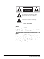
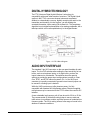
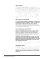
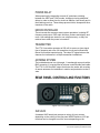
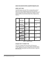
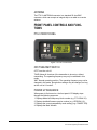
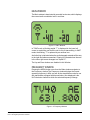
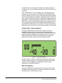
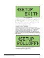
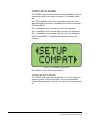
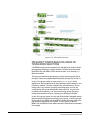
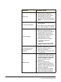
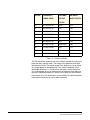
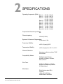
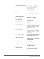
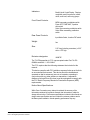
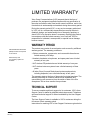
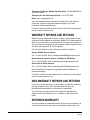
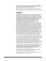
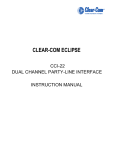
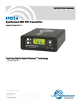
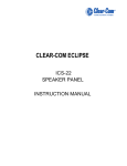
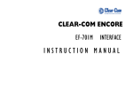
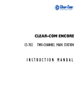
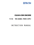
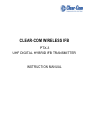
CLEAR-COM WIRELESS IFB
PTX-3
UHF DIGITAL HYBRID IFB TRANSMITTER
INSTRUCTION MANUAL
PTX-3 UHF Digital Hybrid IFB Transmitter Instruction Manual
© 2008 Vitec Group Communications Ltd. All rights reserved.
Part Number 810401Z Rev. 2
Vitec Group Communications LLC
850 Marina Village Parkway
Alameda, CA 94501
U.S.A
Vitec Group Communications Ltd
7400 Beach Drive
IQ Cambridge
Cambridgeshire
United Kingdom
CB25 9TP
Vitec Group Communications
Room 1806, Hua Bin Building
No. 8 Yong An Dong Li
Jian Guo Men Wai Ave
Chao Yang District
Beijing, P.R. China 100022
® Clear-Com, CellCom/FreeSpeak and the Clear-Com Communication Systems logo are registered trademarks of The Vitec Group plc.
CONTENTS
Introduction . . . . . . . . . . . . . . . . . . . . . . . . . . . . . . . . . . . . . . . . . . . . 1-1
Digital Hybrid Technology . . . . . . . . . . . . . . . . . . . . . . . . . . . . . . . . . 1-2
Audio Input Interface. . . . . . . . . . . . . . . . . . . . . . . . . . . . . . . . . . . . . 1-2
Input Limiter . . . . . . . . . . . . . . . . . . . . . . . . . . . . . . . . . . . . . . . . . 1-3
DSP Compatibility Modes . . . . . . . . . . . . . . . . . . . . . . . . . . . . . . . 1-3
Pilot Tone Squelch System . . . . . . . . . . . . . . . . . . . . . . . . . . . . . . 1-3
Frequency Agility. . . . . . . . . . . . . . . . . . . . . . . . . . . . . . . . . . . . . . 1-3
Power Delay . . . . . . . . . . . . . . . . . . . . . . . . . . . . . . . . . . . . . . . . . 1-4
Microcontroller. . . . . . . . . . . . . . . . . . . . . . . . . . . . . . . . . . . . . . . . 1-4
Transmitter . . . . . . . . . . . . . . . . . . . . . . . . . . . . . . . . . . . . . . . . . . 1-4
Antenna System . . . . . . . . . . . . . . . . . . . . . . . . . . . . . . . . . . . . . . 1-4
Rear Panel Controls and Functions . . . . . . . . . . . . . . . . . . . . . . . . . 1-4
XLR Jack. . . . . . . . . . . . . . . . . . . . . . . . . . . . . . . . . . . . . . . . . . . . 1-4
Mode Switches . . . . . . . . . . . . . . . . . . . . . . . . . . . . . . . . . . . . . . . 1-5
Power Input Connector . . . . . . . . . . . . . . . . . . . . . . . . . . . . . . . . . 1-5
Antenna. . . . . . . . . . . . . . . . . . . . . . . . . . . . . . . . . . . . . . . . . . . . . 1-6
Front Panel Controls and Functions . . . . . . . . . . . . . . . . . . . . . . . . . 1-6
PTX-3 Front Panel. . . . . . . . . . . . . . . . . . . . . . . . . . . . . . . . . . . . . 1-6
OFF/TUNE/XMIT Switch . . . . . . . . . . . . . . . . . . . . . . . . . . . . . . . . 1-6
Power Up Sequence . . . . . . . . . . . . . . . . . . . . . . . . . . . . . . . . . . . 1-6
Main Window. . . . . . . . . . . . . . . . . . . . . . . . . . . . . . . . . . . . . . . . . 1-7
Frequency Window . . . . . . . . . . . . . . . . . . . . . . . . . . . . . . . . . . . . 1-7
Audio Input Gain Window . . . . . . . . . . . . . . . . . . . . . . . . . . . . . . . 1-8
Setup WIndow . . . . . . . . . . . . . . . . . . . . . . . . . . . . . . . . . . . . . . . . 1-8
Rolloff Setup Screen . . . . . . . . . . . . . . . . . . . . . . . . . . . . . . . . . . . 1-9
COMPAT Setup Screen. . . . . . . . . . . . . . . . . . . . . . . . . . . . . . . . 1-10
TUNING Setup Screen . . . . . . . . . . . . . . . . . . . . . . . . . . . . . . . . 1-10
Frequency Window Behavior, based on TUNING mode selections .
1-12
User Programmable Frequency Group Behavior . . . . . . . . . . . . 1-13
Adding/Deleting User Programmable Frequency Group Entries 1-13
Installation and Operation. . . . . . . . . . . . . . . . . . . . . . . . . . . . . . . . 1-13
Operating Notes . . . . . . . . . . . . . . . . . . . . . . . . . . . . . . . . . . . . . . . 1-15
Troubleshooting . . . . . . . . . . . . . . . . . . . . . . . . . . . . . . . . . . . . . . . 1-15
Frequency Blocks and Ranges. . . . . . . . . . . . . . . . . . . . . . . . . . . . 1-17
Warranty Period . . . . . . . . . . . . . . . . . . . . . . . . . . . . . . . . . . . . . . . . W-i
Technical Support . . . . . . . . . . . . . . . . . . . . . . . . . . . . . . . . . . . . . . . W-i
Vitec Group Communications
PTX-3 UHF Digital Hybrid IFB Transmitter
i
Warranty Repairs and Returns . . . . . . . . . . . . . . . . . . . . . . . . . . . . W-ii
Non-Warranty Repairs and Returns . . . . . . . . . . . . . . . . . . . . . . . . W-ii
Extended Warranty . . . . . . . . . . . . . . . . . . . . . . . . . . . . . . . . . . . . . W-ii
Liability . . . . . . . . . . . . . . . . . . . . . . . . . . . . . . . . . . . . . . . . . . . . . . W-iii
ii
Vitec Group Communications
PTX-3 UHF Digital Hybrid IFB Transmitter
IMPORTANT SAFETY INSTRUCTIONS
Please read and follow these
instructions before operating
this product.
1. Read these instructions.
2. Keep these instructions.
3. Heed all warnings.
4. Follow all instructions.
5. Do not use this apparatus near water.
6. Clean only with dry cloth.
7. Do not block any ventilation openings. Install in accordance with the
manufacturer’s instructions.
8. Do not install near any heat sources such as radiators, heat
registers, stoves, or other apparatus (including amplifiers) that
produce heat.
9. Only use attachments/accessories specified by the manufacturer.
10. Use only with the cart, stand, tripod, bracket, or table specified by
the manufacturer, or sold with the apparatus. When a cart is used,
use caution when moving the cart/apparatus combination to avoid
injury from tip-over.
11. Unplug this apparatus during lightning storms or when unused for
long periods of time.
12. Refer all servicing to qualified service personnel. Servicing is
required when the apparatus has been damaged in any way, such
as power-supply cord or plug is damaged, liquid has been spilled or
objects have fallen into the apparatus, the apparatus has been
exposed to rain or moisture, does not operate normally, or has been
dropped.
13. WARNING: To reduce the risk of fire or electric shock, do not
expose this product to rain or moisture.
Please familiarize yourself with the safety symbols in Figure 1.
When you see these symbols on this product, they warn you of
the potential danger of electric shock if the station is used
improperly. They also refer you to important operating and
maintenance instructions in the manual.
Vitec Group Communications
PTX-3 UHF Digital Hybrid IFB Transmitter
i
CAUTION
RISK OF ELECTRIC SHOCK
DO NOT OPEN
This symbol alerts you to the presence of uninsulated dangerous
voltage within the product's enclosure that might be of sufficient
magnitude to constitute a risk of electric shock. Do not open
the product's case.
This symbol informs you that important operating and maintenance instructions are included in the literature accompanying
this product.
Figure 1: Safety Symbols
SAFETY
Emission designator: 180KF3E
The T4 IFB transmitter is FCC type accepted under Part 74: 470 608MHz, 614 - 806MHz and 944.1 - 951.9MHz.
The FCC requires that the following statement be included in this
manual:
This device complies with FCC radiation exposure limits as set
forth for an uncontrolled environment. This device should be
installed and operated so that its antenna(s) are not co-located or
operating in conjunction with any other antenna or transmitter. A
separation distance of at least 20cm (8 inches) must be
maintained to comply with the FCC Radio Frequency Maximum
Permissible Exposure (MPE) requirements.
ii
Vitec Group Communications
PTX-3 UHF Digital Hybrid IFB Transmitter
1
GENERAL TECHNICAL
DESCRIPTION
INTRODUCTION
The PTX-3 adds DSP capability and a convenient LCD interface to this
popular IFB transmitter, with the same physical size and interface
capabilities. The PTX-3 also offers new features such as selectable LF
roll-off and compatibility with some other popular brands.
The features include a graphics type backlit LCD display with a menu
system. The PTX-3 can be “Locked” to prevent a user from changing
any settings but still allow browsing of the current settings.
Figure 1-1: PTX-3 Digital Hybrid IFB Transmitter
The transmitter can be powered from any external DC source of 6 to
18 Volts at 200 mA maximum or from the provided 12 Volt power
supply with a locking power connector. The unit has an internal
self-resetting fuse and reverse polarity protection.
The PTX-3 is housed in a machined aluminum case with a tough
electrostatic powder coating. The front and rear panels are anodized
aluminum with laser etched engraving. The included antenna is a right
angle, ¼ wavelength monopole with a BNC connector, constructed of
polymer coated flexible steel cable.
These features, along with 250 milliwatt RF output power and a wide
range of selectable audio input types and levels, make the PTX-3 an
excellent choice for IFB and other applications where extended
operating range is required.
Vitec Group Communications
PTX-3 UHF Digital Hybrid IFB Transmitter
1-1
DIGITAL HYBRID TECHNOLOGY
The PTX-3 features Digital Hybrid Wireless* technology for
compatibility with some other brands of receivers. The Digital Hybrid
system in the PTX-3 overcomes channel noise and compandor
artifacts in a dramatically new way, digitally encoding the audio in the
transmitter and decoding it in the receiver, yet still sending the
encoded information via an analog FM wireless link. This proprietary
algorithm is not a digital implementation of an analog compandor, but a
technique which can be accomplished only in the digital domain.
Figure 1-2: PTX-3 Block Diagram
AUDIO INPUT INTERFACE
The standard 3 pin XLR connector on the rear panel handles all audio
inputs. The four DIP switches allow setting the input sensitivity for low
levels, such as microphone inputs, or for high levels, such as line
inputs, balanced or unbalanced. The switches also offer special
settings to provide the proper input configurations to match to Clear
Com, RTS1, and RTS2 intercom systems. Pin 1 of the XLR input
connector is normally connected to ground but an internal jumper can
be moved if a floating input is desired.
While the XLR input does not offer phantom power, it is fully
compatible with standard 48 Volt phantom power. Phantom supplied
microphones may be connected to the PTX-3 without the need for DC
isolation.
A user-selectable low frequency roll-off can be set for 35 Hz or 50 Hz.
The recommended 50 Hz default setting helps to remove wind and
traffic noise, air conditioner rumble, and other sources of undesired low
frequency audio. The 35 Hz setting offers a fuller range of sound in the
absence of adverse conditions.
1-2
Vitec Group Communications
PTX-3 UHF Digital Hybrid IFB Transmitter
INPUT LIMITER
A DSP controlled analog audio limiter is employed before the
analog-to-digital converter. The limiter has a range of more than 30 dB
for excellent overload protection. A dual release envelope makes the
limiter acoustically transparent while maintaining low distortion. It can
be thought of as two limiters in series: a fast attack and release limiter
followed by a slower attack and release limiter. The dual release limiter
recovers quickly from brief transients but recovers more slowly from
sustained high levels, keeping audio distortion low while preserving
short term dynamic changes. When the audio meter on the LCD
display widens slightly as it reaches zero, limiting is indicated. When
the zero changes to a letter C, severe limiting and/or clipping is
indicated.
DSP COMPATIBILITY MODES
As a DSP based design, compatibility with a variety of different analog
and digital hybrid receivers is possible. The primary noise reduction in
the IFB system is a single band compandor with pre-emphasis.
When the PTX-3 is configured for compatibility with other types of
wireless systems; the DSP emulates the appropriate audio processing
and companding for the chosen mode.
PILOT TONE SQUELCH SYSTEM
Clear-Com IFB systems use a special “pilot tone” so that valid IFB
signals can be distinguished from RF interference. During normal
operation, an IFB receiver will listen for the distinctive pilot tone,
remaining silent (squelched) until the pilot tone is detected. The pilot
tone is located well above audio frequencies and is never passed
through to the receiver’s audio output.
The benefit of the pilot tone squelch system is that the receiver will
remain muted until it receives an RF carrier strong enough for good
reception and the pilot tone from the matching transmitter. Even strong
interfering RF signals on the carrier frequency of the system will not
open the squelch on the receiver.
When the PTX-3 is operated in compatibility modes other than IFB, it
generates pilot tones as appropriate for the chosen mode.
FREQUENCY AGILITY
The PTX-3 transmitter uses a synthesized, frequency selectable main
oscillator. The frequency is extremely stable over a wide temperature
range and over time. The transmitter’s standard tuning range covers
256 frequencies in 100 kHz steps over a 25.6 MHz band. This flexibility
significantly helps avoid interference problems in mobile or traveling
applications.
Vitec Group Communications
PTX-3 UHF Digital Hybrid IFB Transmitter
1-3
POWER DELAY
When powering the transmitter on and off, and when switching
between the XMIT and TUNE modes, intelligent circuitry adds brief
delays in order to allow time for circuits to stabilize, both locally and in
the matching receiver. These delays prevent clicks, thumps and other
transients in the audio.
MICROCONTROLLER
The microcontroller oversees most system operations, including RF
frequency and output, DSP audio functions, buttons and display, and
more. User settings are stored in non-volatile memory, so they are
retained even when the power is turned off.
TRANSMITTER
The PTX-3 transmitter operates at 250 mW to ensure a clean signal
free of dropouts and noise. All transmitter circuits are buffered and
filtered for excellent spectral purity. The clean RF signal reduces the
chances for interference in multiple transmitter installations.
ANTENNA SYSTEM
The included antenna is a right angle, ¼ wavelength monopole with a
BNC connector. It is constructed of polymer coated flexible steel cable.
The PTX-3’s 50 Ohm BNC output connector also works with a variety
of remote antennas for installation in studios and production trucks &
vans.
REAR PANEL CONTROLS AND FUNCTIONS
Figure 1-3: PTX-3 Rear Panel
XLR JACK
A standard XLR female jack accepts a variety of input sources
depending on the setting of the rear panel MODE switches. XLR pin
functions can be changed to suit the source depending on the
1-4
Vitec Group Communications
PTX-3 UHF Digital Hybrid IFB Transmitter
positions of the individual switches. For detailed information on the
setting of these switches see the Installation and Operation section.
MODE SWITCHES
The MODE switches allow the PTX-3 to accommodate a variety of
input source levels by changing the input sensitivity and the pin
functions of the input XLR jack. Marked on the rear panel are the most
common settings. Each setting is detailed below. Switches 1 and 2
adjust the XLR pin functions while switches 3 and 4 adjust the input
sensitivity.
NAME
SWITCH
XLR PINS
BALANCED
POSITIONS
INPUT
SENSITIVITY
1 2 3 4
CC
3=Audio
1=Common
No
-10 dBu
MIC
2=Hi
3=Lo
1=Common
Yes
-42 dBu
LINE
2=Hi
3=Lo
1=Common
Yes
0 dBu
RTS1
2=Hi
1=Common
No
0 dBu
RTS2
3=Hi
1=Common
No
0 dBu
Table 1-1: Mode Switches
POWER INPUT CONNECTOR
The PTX-3 is designed to be used with the CH20 external (or
equivalent) power source. The nominal voltage to operate the unit is
12 VDC, although it will operate at voltages as low as 6 VDC and as
high as 18 VDC. External power sources must be able to supply 200
mA continuously.
Vitec Group Communications
PTX-3 UHF Digital Hybrid IFB Transmitter
1-5
ANTENNA
The PTX-3’s ANTENNA connector is a standard 50 ohm BNC
connector, which can accept an integral whip or a cable to a remote
antenna.
FRONT PANEL CONTROLS AND FUNCTIONS
PTX-3 FRONT PANEL
Figure 1-4: PTX-3 Front Panel
OFF/TUNE/XMIT SWITCH
OFF Turns the unit off.
TUNE Allows all functions of the transmitter to be set up, without
transmitting. The operating frequency may only be selected in this
mode.
XMIT Normal operating position. The operating frequency may not be
changed in this mode, though other settings may be changed, so long
as the unit isn’t “Locked”.
POWER UP SEQUENCE
When power is first turned on, the front panel LCD display steps
through the following sequence.
1. Displays Model and frequency block number (e.g. PTX-3 BLK 25).
2. Displays installed firmware version number (e.g. VERSION 1.0).
3. Displays the current compatibility mode setting (e.g. COMPAT IFB).
4. Displays the Main Window.
1-6
Vitec Group Communications
PTX-3 UHF Digital Hybrid IFB Transmitter
MAIN WINDOW
The Main window is dominated by an audio level meter, which displays
the current audio modulation level in real time.
Figure 1-5: Main Window
In TUNE mode, a blinking capital “T” is displayed in the lower left
corner to remind the user that the unit is not yet transmitting. In XMIT
mode, the blinking “T” is replaced by an antenna icon.
Audio limiting is indicated when the audio bargraph extends all the way
to the right and widens somewhat. Clipping is indicated when the zero
in the lower right corner changes to a capital “C”.
The Up and Down buttons are disabled in this Window.
FREQUENCY WINDOW
Pressing the MENU button once from the Main window navigates to
the Frequency window.The Frequency window displays the current
operating frequency in MHz, as well as the standard hex code for use
with transmitters equipped with hex switches. Also displayed is the
UHF television channel to which the selected frequency belongs.
Figure 1-6: Frequency Window
Vitec Group Communications
PTX-3 UHF Digital Hybrid IFB Transmitter
1-7
In XMIT mode, it is not possible to change the operating frequency.
In TUNE mode, the Up and Down buttons may be used to select a new
frequency.
If the TUNING mode is set to NORMAL, the Up and Down buttons
navigate in 100 kHz increments, and MENU+Up and MENU+Down
move 16 channels at a time. In any of the various group tuning modes,
the currently selected group identifier is displayed to the left of the hex
code, and the Up and Down buttons navigate among the frequencies
in the group. In factory group tuning modes A thru D, MENU+Up and
MENU+Down jump to the highest and lowest frequencies in the group.
In user group tuning modes U and V, MENU+Up and MENU+Down
permit access to frequencies not currently in the group. Pressing and
holding the Up or Down button scrolls quickly through the entire range.
AUDIO INPUT GAIN WINDOW
Pressing the MENU button once from the Frequency window
navigates to the Audio Input Gain window. This window greatly
resembles the Main window, with the exception that the current audio
input gain setting is displayed in the upper left corner. The Up and
Down buttons may be used to alter the setting while reading the
realtime audio meter to determine what setting works best.
Figure 1-7: Input Gain Window
The gain range is -18 dB to +24 dB with 0 dB nominal center. The
reference for this control can be changed with the rear panel MODE
switches. See the Installation and Operation section for more
information on the MODE switches.
SETUP WINDOW
Pressing the MENU button once from the Audio Input Gain window
navigates to the Setup window. This window contains a menu which
permits access to various setup screens.
1-8
Vitec Group Communications
PTX-3 UHF Digital Hybrid IFB Transmitter
Figure 1-8: Setup Window
Initially the active menu item is EXIT. Pressing the Up and Down keys
permits navigation among the remaining menu items: TUNING,
COMPAT and ROLLOFF.
Pressing the MENU button selects the current menu item. Selecting
EXIT navigates back to the Main window. Selecting any other item
navigates to the associated setup screen.
ROLLOFF SETUP SCREEN
The ROLLOFF setup screen controls the low frequency audio
response of the PTX-3 by moving the 3 dB corner of a 4 pole lowpass
digital filter. The 50 Hz setting is the default, and should be used
whenever wind noise, HVAC rumble, traffic noise or other low
frequency sounds may degrade the quality of the audio. The 35 Hz
setting may be used in the absence of adverse conditions, for a fuller
bass response.
Figure 1-9: ROLLOFF Setup Screen
Press MENU to return to the Setup window.
Vitec Group Communications
PTX-3 UHF Digital Hybrid IFB Transmitter
1-9
COMPAT SETUP SCREEN
The COMPAT setup screen selects the current compatibility mode, for
interoperation with various types of receivers. The available modes
are:
IFB - IFB compatibility mode. This is the default setting and is the
appropriate setting to use with a compatible IFB receiver such as the
Clear-Com PRC-2.
400 - Compatibility mode for some non Clear-Com equipment.
100 - Compatibility mode for some older non Clear-Com equipment.
200 - Compatibility mode for some older non Clear-Com equipment.
MODE 3 and MODE 6 - Compatible with certain non Clear-Com
receivers.
Figure 1-10: Compatibility Setup Screen
Press MENU to return to the Setup window.
TUNING SETUP SCREEN
The TUNING setup screen allows selection of one of four factory set
frequency groups (Groups A through D), two user programmable
frequency groups (Groups U and V) or the choice to not use groups at
all.
1-10
Vitec Group Communications
PTX-3 UHF Digital Hybrid IFB Transmitter
Figure 1-11: Tuning Setup Screen
In the four factory set frequency groups, eight frequencies per group
are preselected. These frequencies are chosen to be free of
intermodulation products. (Refer to receiver manual for more
information).
in the two user programmable frequency groups, up to 16 frequencies
can be programmed per group.
Note: The TUNING Setup Screen only selects the tuning mode
(NORMAL or Group tuning) and not the operating
frequency. Actual operating frequencies are chosen
through the Frequency Window.
Press MENU to return to the Setup window.
Vitec Group Communications
PTX-3 UHF Digital Hybrid IFB Transmitter
1-11
Figure 1-12: PTX-3 Menu Structure
FREQUENCY WINDOW BEHAVIOR, BASED ON
TUNING MODE SELECTIONS
If NORMAL tuning mode is selected, the Up and Down buttons select
the operating frequency in single channel (100 kHz) increments and
the MENU+Up and MENU+Down shortcuts tune in 16 channel (1.6
MHz) increments.
There are two classes of group tuning: factory preset groups (Grp A
through D) and user programmable frequency groups (Grp U and V).
In any of the group modes, a lower case a, b, c, d, u or v will be
displayed to the immediate left of the transmitter switch settings in the
Frequency window. The letter identifies the selected factory or user
tuning group. Any time the currently tuned frequency is not in the
current group, this group identification letter will blink. Any time the
currently tuned frequency is in the current tuning group, the group
tuning mode indicator will give a steady (non-blinking) indication.
In any of the group modes, the Up and Down buttons navigate among
the selected intermod-free frequencies in the group. In factory groups
(A through D), the MENU+Up and MENU+Down shortcuts jump to the
first and last frequencies in the group. In user groups (U and V),
MENU+Up and MENU+Down permit access to frequencies not already
in the group.
1-12
Vitec Group Communications
PTX-3 UHF Digital Hybrid IFB Transmitter
USER PROGRAMMABLE FREQUENCY GROUP
BEHAVIOR
The user programmable frequency groups “U” or “V” work very
similarly to the factory groups with a few exceptions. The most obvious
difference is the ability to add or remove frequencies from the group.
Less obvious is the behavior of a user programmable frequency group
with only one entry, or with no entries.
A user programmable frequency group with only one entry continues to
display the single frequency stored in the group no matter how many
times the Up or Down buttons are pressed (provided the MENU button
is not pressed at the same time). The “U” or “V” will not blink.
A user programmable frequency group with no entries reverts to
non-group-mode behavior, i.e., access is allowed to all 256 available
frequencies in the selected receiver module’s frequency block. When
there are no entries, the “U” or “V” will of course blink. However, once a
frequency has been added to the tuning group, this behavior changes
to group-mode behavior where the MENU button must be pressed and
held while either the Up or Down buttons are pressed to access
frequencies that are not part of the current tuning group.
ADDING/DELETING USER PROGRAMMABLE
FREQUENCY GROUP ENTRIES
Note: Each User Programmable Frequency Group (“u” or “v”) has
separate contents. We recommend that you consider the larger issue
of frequency coordination prior to adding frequencies in order to
minimize potential intermodulation problems.
1. Start from the Frequency window and verify that a lower case “u” or
“v” is present next to the transmitter switch settings.
2. While pressing and holding the MENU button press either the Up or
Down button to move to one of the 256 available frequencies in the
block. Whenever the selection comes to rest on a frequency that is
in the current group, the group tuning mode indicator (letter “u” or
“v”) will give a steady indication. On frequencies that are not in the
group, the indicator will blink.
3. To add or remove the displayed frequency from the group, hold
down the MENU button while pressing and holding the Up button.
The group tuning mode indicator will stop blinking to show that the
frequency has been added to the group, or begin blinking to indicate
that the frequency has been removed from the group.
INSTALLATION AND OPERATION
1. The PTX-3 transmitter is shipped with pin 1 of the XLR input
connector tied directly to ground. If a floating input is desired, a
Ground Lift Jumper is provided. This jumper is located inside the
unit on the PC board near the rear panel XLR jack. For floating
Vitec Group Communications
PTX-3 UHF Digital Hybrid IFB Transmitter
1-13
input, disconnect the power supply, open the unit and move the
Ground Lift Jumper to the desired location.
Figure 1-13: Jumper in Ground Position
Figure 1-14: Jumper in Lift Position
Figure 1-15: PTX-3 Ground Lift Jumper
2. Set the MODE switches on the rear panel to match the specific input
source to be used. (See MODE Switches.)
3. Insert the power supply plug into the 6-18 VDC jack on the rear
panel.
4. Insert the microphone or other audio source XLR plug into the input
jack. Ensure that the pins are aligned and that the connector locks
into place.
5. Attach the antenna (or antenna cable) to the BNC connector on the
rear panel.
6. Set the OFF/TUNE/XMIT switch to TUNE.
1-14
Vitec Group Communications
PTX-3 UHF Digital Hybrid IFB Transmitter
7. Press the MENU button to display the Frequency Window and
adjust the transmitter to the desired frequency with the front panel
Up and Down buttons.
8. Position the microphone. The microphone should be placed where it
will be located during actual use.
OPERATING NOTES
The AUDIO LEVEL control should not be used to control the volume of
the associated receiver. This gain adjustment is used to match the
PTX-3 input level to the incoming signal from the sound source to
provide full modulation and maximum dynamic range, not to set the
volume of the associated receiver.
If the audio level is too high — the audio metering will exceed the 0 dB
level too frequently. This condition may reduce the dynamic range of
the audio signal.
If the audio level is too low — the audio metering will be too far below
the 0 dB level. This condition may cause hiss and noise in the audio, or
pumping and breathing in the background noise.
The input limiter will handle peaks over 15 dB above full modulation,
regardless of the gain control setting. Occasional limiting is often
deemed desirable, indicating that the gain is correctly set and the
transmitter is fully modulated for optimum signal to noise ratio.
Different voices will usually require different audio input gain settings,
so check this adjustment as each new person uses the system. If
several different people will be using the transmitter and there is not
time to make the adjustment for each individual, adjust it for the
loudest voice.
TROUBLESHOOTING
Note: Always ensure that the COMPAT (compatibility) setting is
the same on both transmitter and receiver. A variety of
different symptoms will occur if the settings do not match.
With the PRC-2 receiver no sound will be heard unless the transmitter
is set to the IFB mode. When used with receivers other than the
PRC-2, a variety of symptoms will occur when the COMPAT settings
do not match, ranging from no sound, to level inconsistencies, to
distortion of various degrees.
See the section entitled Front Panel Controls and Functions for details
on the available compatibility modes and how to select them.
Vitec Group Communications
PTX-3 UHF Digital Hybrid IFB Transmitter
1-15
1-16
SYMPTOM
POSSIBLE CAUSE
Display Dead
1. External power supply
disconnected or inadequate.
2. The External DC power input is
protected by an auto-reset
polyfuse. Disconnect power and
wait about 1 minute for the fuse to
reset.
No Transmitter Modulation
1. Audio input gain setting turned all
the way down.
2. Sound source off or malfunctioning.
3. Input cable damaged or miswired.
No Received Signal
1. Transmitter not turned on.
2. Receiver antenna missing or
improperly positioned (the PRC-2
headset cable is the antenna).
3. Transmitter and receiver not on
same frequency. Check on
transmitter and receiver.
4. Operating range is too great.
5. Transmitter antenna not
connected.
6. Transmitter switch in the TUNE
position. Switch to XMIT mode.
No Sound (or Low Sound
Level); and Receiver is
powered on
1. Receiver output level set too low.
2. Receiver earphone cable is
defective or miswired.
3. Sound system or transmitter input
is turned down.
Distorted Sound
1. Transmitter gain (audio level) is far
too high. Check audio level meter
on transmitter as it is being used
(refer to Installation & Operation
section for details on gain
adjustment).
2. Receiver output may be
mismatched with the headset or
earphone. Adjust output level on
receiver to the correct level for the
headset or earphone.
3. Excessive wind noise or breath
“pops”. Reposition microphone
and/or use a larger windscreen.
Vitec Group Communications
PTX-3 UHF Digital Hybrid IFB Transmitter
SYMPTOM
POSSIBLE CAUSE
Hiss, Noise or Audible
Dropouts
1. Transmitter gain (audio level) far
too low.
2. Receiver antenna missing or
obstructed (the PRC-2 headset
cable is the antenna).
3. Transmitter antenna missing or
mismatched. Check that the
correct antenna is being used.
4. Operating range too great.
5. Defective remote antenna or cable.
Antenna Icon (in Main Window)
or Hex Code (in Frequency
Window) Blinking
1. PLL is unlocked. Retune
transmitter. Factory service may be
required if problem persists.
Table 1-2: Troubleshooting Tips
FREQUENCY BLOCKS AND RANGES
The table below lists the factory designated frequency ranges available
for the PTX-3 Transmitter.
Each PTX-3 transmitter is built to cover a pre-selected range of
frequencies (a “block”) as shown below. The transmitter will tune to
any of 256 different frequencies within this factory assigned block
(except blocks 23 and 944).
The block number is determined by this formula:
25.6 × Block = Lowest frequency (MHz) in the block
To determine a block number from a frequency:
Freq. (MHz) divided by 25.6 = Block number
It is handy to remember these formulas, in case you do not have a
copy of the table. For example, suppose you need to know which block
covers 685.500 MHz, which is in the middle of the Block 26 frequency
range.
685.500 divided by 25.6 = 26.77734375
The first two digits left of the decimal are the block number. In this
case, 685.500 MHz falls within block 26. Block 944 is an exception to
this block numbering system and depicts the actual frequency of the
block since it is a special case in an 8 MHz band with 78 frequency
channels.
Vitec Group Communications
PTX-3 UHF Digital Hybrid IFB Transmitter
1-17
BLOCK
FREQUENCY
ANTENNA
ANTENNA
RANGE (MHZ)
SLEEVE
WHIP LENGTH
COLOR
21
537.600-563.100
Brown
4.74”
22
563.200-588.700
Red
4.48”
23
588.800-614.300
Orange
4.24”
24
614.400-639.900
Yellow
4.01”
25
640.000-665.500
Green
3.81”
26
665.600-691.100
Blue
3.62”
27
691.200-716.700
Violet (Pink)
3.46”
28
716.800-742.300
Grey
3.31”
29
742.400-767.900
White
3.18”
944
944.100-951.900
Black
2.74”
Table 1-3: Frequency Blocks
The IFB transmitter antennas are color coded to indicate the frequency
block that they operate within. The length of the antenna varies with
the frequency block. The actual length of the antenna is not as critical
as it might appear in the table below. The usable bandwidth of the
detachable antenna is +/- 50 MHz from the block’s center frequency,
so it is acceptable to use an antenna from an adjacent block above or
below the operating frequency if some loss in range can be tolerated.
Part of block 23 is not used since it covers a 608 to 614 MHz band that
is allocated exclusively for use in radio astronomy.
1-18
Vitec Group Communications
PTX-3 UHF Digital Hybrid IFB Transmitter
2
SPECIFICATIONS
Operating frequencies (MHz):
Block 21
Block 22
Block 23
537.600 - 563.100
563.200 - 588.700
588.800 - 607.900
614.100 - 614.300
Block 24 614.400 - 639.900
Block 25 640.000 - 665.500
Block 26 665.600 - 691.100
Block 27 691.200 - 716.700
Block 28 716.800 - 742.300
Block 29 742.400 - 767.900
Block 944 944.100 - 951.900
Frequencies Channels per block):
256
Channel spacing:
100 kHz (0.1 MHz)
Spurious & Harmonic Suppression:
37 dBc above 1 GHz
Frequency Stability:
±.001% (10 ppm) @ 25ºC
Temperature Stability:
±.001% (10 ppm) from -30º C to +50º C
Channel Selection:
Momentary pushbutton switches, TUNE
UP and Down
Compatibility Modes:
IFB, Digital Hybrid Wireless
400 Mode, 200 Mode, 100 Mode,
Mode 3, Mode 6
Pilot Tone:
29.997 kHz IFB Mode, 32.765kHz
200 Mode, 400 Mode step selected,
32.768kHz Mode 6
Modulation:
FM, ±20 kHz deviation IFB &
100 Mode,
±75kHz 200 & 400 Mode,
±50kHz Mode 3 and Mode 6
Vitec Group Communications
PTX-3 UHF Digital Hybrid IFB Transmitter
2-1
Audio Frequency Response:
100 Hz to 8 kHz, ±1 dB, IFB MODE
system response (see Rolloff)
30Hz to 20kHz ± 1dB,
200 & 400 MODE system
response (see Rolloff)
Rolloff:
Low frequency audio rolloff is Menu
selectable for 3 dB down at 35 Hz or 50
Hz
Signal to Noise Ratio:
90 dB typical (“A” weighted)
RF Power Output:
250 mW (nominal)
Output Impedance:
50 Ohms
Audio Input Levels:
0 dBu for Line, RTS1 & RTS2, -10 dBu
for ClearCom, and -42 dBu mic dry
inputs, +/-50VDC max
Audio Input Config:
Balanced and Unbalanced, rear panel
selectable for Line, Mic, RTS 1, RTS 2
and ClearCom
Audio Input Impedance:
Greater than 2 K balanced, greater than
1K unbalanced at any gain setting
Gain Control Range:
-18 dB to +24 dB (0 dB nominal center),
software selectable
Audio Input Jack:
Standard XLR female connector
Input Power:
12 to 14 VDC typical, 200 mA max; Max
input range 6 to 18 VDC
Power Input Jack:
Coax type, locking LZR RL26AE
2-2
Vitec Group Communications
PTX-3 UHF Digital Hybrid IFB Transmitter
Indicators:
Backlit Liquid Crystal Display. Displays
modulation meter, frequencies, modes,
rolloff, audio level, and tuning groups
Front Panel Controls:
MENU momentary pushbutton switch
Power OFF-TUNE-XMIT, 3 position
slide switch
Select Up momentary pushbutton switch
Select Down momentary pushbutton
switch
Rear Panel Controls:
Input Mode Select, 4 section DIP switch
Weight:
9oz
Size:
5.25” long (including connectors) x 3.25”
wide x 1.25” high
Emission designator:
180KF3E
The T4 IFB transmitter is FCC type accepted under Part 74:470 608MHz and 944.1 - 951.9 MHz
The FCC requires that the following statement be included in this
manual:
This device complies with FCC radiation exposure limits as set forth for
an uncontrolled environment. This device should be installed and
operated so that its antenna(s) are not co-located or operating in
conjunction with any other antenna or transmitter. A separation
distance of at least 20cm (8 inches) must be maintained to comply with
the FCC Radio Frequency Maximum Permissible Exposure (MPE)
requirements.
Notice About Specifications
While Clear-Com makes every attempt to maintain the accuracy of the
information contained in its product manuals, that information is subject to
change without notice. Performance specifications included in this manual are
design-center specifications and are included for customer guidance and to
facilitate system installation. Actual operating performance may vary.
Vitec Group Communications
PTX-3 UHF Digital Hybrid IFB Transmitter
2-3
2-4
Vitec Group Communications
PTX-3 UHF Digital Hybrid IFB Transmitter
LIMITED WARRANTY
Vitec Group Communications (VGC) warrants that at the time of
purchase, the equipment supplied complies with any specification in
the order confirmation when used under normal conditions, and is free
from defects in workmanship and materials during the warranty period.
During the warranty period VGC, or any service company authorized
by VGC, will in a commercially reasonable time remedy defects in
materials, design, and workmanship free of charge by repairing, or
should VGC in its discretion deem it necessary, replacing the product
in accordance with this limited warranty. In no event will VGC be
responsible for incidental, consequential, or special loss or damage,
however caused.
WARRANTY PERIOD
Return Material Authorization
(RMA) numbers are required
for all returns.
Both warranty and
non-warranty repairs are
available.
The product may consist of several parts, each covered by a different
warranty period. The warranty periods are:
• Cables, accessories, components, and consumable items have a
limited warranty of 90 days.
• Headsets, handsets, microphones, and spare parts have a limited
warranty of one year.
• UHF wireless IFB products have a limited warranty of one year.
• UHF wireless intercom systems have a limited warranty of three
years.
• All other Clear-Com and Drake brand systems and products,
including beltpacks, have a limited warranty of two years.
The warranty starts at the time of the product’s original purchase. The
warranty start date for contracts which include installation and
commissioning will commence from the earlier of date of the Site
Acceptance Test or three months from purchase.
TECHNICAL SUPPORT
To ensure complete and timely support to its customers, VGC’s User
Support Center is staffed by qualified technical personnel. Telephone
and email technical support is offered worldwide by the User Support
Center.
The User Support Center is available to VGC’s customers during the
full course of their warranty period.
Instructions for reaching VGC’s User Support Centers are given below.
Vitec Group Communications
Warranty
i
Telephone for Europe, Middle East and Africa: +49 40 6688 4040 or
+44 1223 815000
Telephone for the Americas and Asia: +1 510 337 6600
Email: [email protected]
Once the standard warranty period has expired, the User Support
Center will continue to provide telephone support if you have
purchased an Extended Warranty.
For latest contact information please refer to the Service and Support
section at www.clearcom.com.
WARRANTY REPAIRS AND RETURNS
Before returning equipment for repair, contact a User Support Center
to obtain a Return Material Authorization (RMA). VGC representatives
will give you instructions and addresses for returning your equipment.
You must ship the equipment at your expense, and the support center
will return the equipment at VGC’s expense.
For out-of-box failures, use the following contact information:
Europe, Middle East and Africa
Tel: +44 1223 815000 Email: [email protected]
North America, Canada, Mexico, Caribbean & US Military
Tel: +1 510 337 6600 Email: [email protected]
Asia Pacific & South America
Tel: +1 510 337 6600 Email: [email protected]
VGC has the right to inspect the equipment and/or installation or
relevant packaging.
For latest contact information please refer to the Service and Support
section at www.clearcom.com.
NON-WARRANTY REPAIRS AND RETURNS
For items not under warranty, you must obtain an RMA by contacting
the User Support Center. VGC representatives will give you
instructions and addresses for returning your equipment.
You must pay all charges to have the equipment shipped to the
support center and returned to you, in addition to the costs of the
repair.
EXTENDED WARRANTY
You can purchase an extended warranty at the time of purchase or at
any time during the first two years of ownership of the product. The
ii
Vitec Group Communications
Warranty
purchase of an extended warranty extends to five years the warranty
of any product offered with a standard two-year warranty. The total
warranty period will not extend beyond five years.
Note: VGC does not offer warranty extensions on UHF wireless
intercom systems, or on any product with a 1-year or 90-day warranty.
LIABILITY
THE FOREGOING WARRANTY IS VGC'S SOLE AND EXCLUSIVE
WARRANTY. THE IMPLIED WARRANTY OF MERCHANTABILITY
AND FITNESS FOR A PARTICULAR PURPOSE AND ANY OTHER
REQUIRED IMPLIED WARRANTY SHALL EXPIRE AT THE END OF
THE WARRANTY PERIOD. THERE ARE NO OTHER WARRANTIES
(INCLUDING WITHOUT LIMITATION WARRANTIES FOR
CONSUMABLES AND OTHER SUPPLIES) OF ANY NATURE
WHATSOEVER, WHETHER ARISING IN CONTRACT, TORT,
NEGLIGENCE OF ANY DEGREE, STRICT LIABILITY OR
OTHERWISE, WITH RESPECT TO THE PRODUCTS OR ANY PART
THEREOF DELIVERED HEREUNDER, OR FOR ANY DAMAGES
AND/OR LOSSES (INCLUDING LOSS OF USE, REVENUE, AND/OR
PROFITS). SOME STATES DO NOT ALLOW THE EXCLUSION OR
LIMITATION OF INCIDENTAL OR CONSEQUENTIAL DAMAGES OR
THE LIMITATION ON HOW LONG AN IMPLIED WARRANTY LASTS,
SO THE ABOVE LIMITATIONS MAY NOT APPLY TO YOU. IN ANY
EVENT, TO THE MAXIMUM EXTENT PERMITTED UNDER
APPLICABLE LAW, VGC'S LIABILITY TO CUSTOMER HEREUNDER
SHALL NOT UNDER ANY CIRCUMSTANCES EXCEED THE COST
OF REPAIRING OR REPLACING ANY PART(S) FOUND TO BE
DEFECTIVE WITHIN THE WARRANTY PERIOD AS AFORESAID.
This warranty does not cover any damage to a product resulting from
cause other than part defect and malfunction. The VGC warranty does
not cover any defect, malfunction, or failure caused beyond the control
of VGC, including unreasonable or negligent operation, abuse,
accident, failure to follow instructions in the manual, defective or
improperly associated equipment, attempts at modification and repair
not approved by VGC, and shipping damage. Products with their serial
numbers removed or defaced are not covered by this warranty.
This warranty does not include defects arising from installation (when
not performed by VGC), lightning, power outages and fluctuations, air
conditioning failure, improper integration with non-approved
components, defects or failures of customer furnished components
resulting in damage to VGC provided product.
This limited warranty is not transferable and cannot be enforced by
anyone other than the original consumer purchaser.
This warranty gives you specific legal rights and you may have other
rights which vary from country to country.
Vitec Group Communications
Warranty
iii
iv
Vitec Group Communications
Warranty