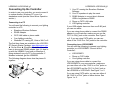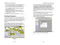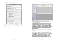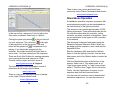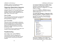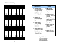
1
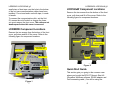
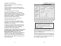
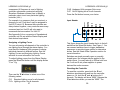
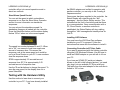
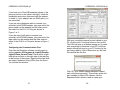
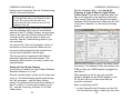
Table of Contents LOR1602W Shown LOR800W & LOR160xW g3 Computerized Light Controller Generation 3 User Manual May 16, 2014 V4.00 Copyright © Light O Rama, Inc. 2006-2014 Introduction ............................................................ 4 What’s in the Box ................................................... 6 Safety Considerations ............................................ 6 LOR800W Component Locations .......................... 7 LOR160xW Component Locations......................... 8 Figure 2 .......................................................... 8 Quick Start Guide................................................... 8 Connecting Up the Controller ............................... 11 Connecting to a PC .......................................... 11 Connecting to an LOR1602MP3....................... 12 Connecting to a Show Director ......................... 13 Connecting to another Controller...................... 13 Creating a Show .................................................. 14 Creating a Show (Full Capabilities) ...................... 14 Power Considerations .......................................... 15 LOR800W and LOR1600W .............................. 15 LOR1602W ...................................................... 15 3-Phase Power ............................................. 16 Christmas Light Power Consumptions ............. 17 Lighting Curves .................................................... 17 Configuring Lighting Curves ................................. 19 Setting Multiple Channels in a Group ............... 22 Setting Individual Channels .............................. 22 Example ........................................................... 22 Hardware Description .......................................... 24 Status Display .................................................. 24 Idle: ............................................................... 24 Connected to LOR Network: ......................... 25 Connected to DMX Universe: ....................... 25 Loading Firmware: ........................................ 25 Resetting:...................................................... 25 Running a Standalone Sequence: ................ 25 Assigning a DMX Address ................................ 26 LOR800W & LOR160xW g3 Assigning a Unit ID ........................................... 26 Assigning a Lighting Curve ............................... 27 Input Header..................................................... 28 Resetting the Controller .................................... 28 Stand Alone Speed Control .............................. 29 Testing with the Hardware Utility.......................... 29 Installing LOR Software .................................... 30 Connecting Controller-to-PC Data Cable ......... 30 Configuring the Communications Port .............. 31 Setting the Unit ID with Software ...................... 33 Creating A Sequence ........................................... 35 Figure 2 ........................................................ 35 Stand Alone Operation......................................... 40 Triggering a Stand-Alone Sequence .................... 41 Power On Mode ............................................... 41 Input Control Mode ........................................... 41 Troubleshooting ................................................... 41 Autoconfigure does not find COM Port ............. 41 Refresh does not find the controller.................. 43 LOR800W or LOR160xW Status Display Blank 44 Channel 9-16 OK, Channels 1-8 No Good ....... 44 Warnings and Liability .......................................... 45 Appendix A Hexadecimal to Decimal ................... 46 Specifications ....................................................... 48 Introduction The Light O Rama (LOR) LOR800Wg3 is an 8 channel and the LOR1600Wg3 and LOR1602Wg3 are 16 channel computerized lighting controllers. The “g3” indicates that they are the third generation in the model line. The LOR800W and LOR1600W are single power cord, 15 amp controllers. The LOR1602W is a dual power cord 30 amp controller. These controllers are designed to control incandescent and line voltage LED lighting. They operate on 120 VAC (240 VAC models are available), 50/60 Hz. The 30 amp configuration can control approximately 9,000 incandescent minilights or 70,000 LED mini-lights or some combination of both. These controllers include “ghost loads” which drain off charge to prevent low brightness LED glow when LEDs should be off. The “ghost loads” also permit smoother LED fading. These controllers use higher reliability output components than the previous generation. These components are more tolerant of overloads and even survive some direct short circuit situations. These controllers provide greater accessory power than previous LOR controllers. This additional power is necessary for future accessories. They understand both LOR and DMX protocols. The g3 firmware included with these controllers has individual channel lighting curves for smooth, glitchfree dimming and effects with LED lighting. This firmware also increases the number of brightness 4 LOR800W & LOR160xW g3 LOR800W & LOR160xW g3 steps from 250 to 1000 for smoother fading with LEDs. Controlled Triac Board (Deluxe) with heavy duty heat sink. As with all LOR controllers, the firmware is field upgradeable so you are guaranteed compatibility with future LOR hardware and software products. To allow your PC to communicate with these controllers, you will need one of Light O Rama’s RS485 adapters. When you purchase the Generic Starter Package, you get the LOR Showtime Software, a 10’ Cat5 network cable and you will be given a choice of several types of USB RS485 adapters or a serial port RS485 adapter. Choose the adapter appropriate for your PC/laptop. The RS485 adapter will allow you to connect your PC/laptop via the Cat5 cable to your lighting controller. These controllers are components in the Showtime Commercial Line of LOR products. They carry the ETL seal certifying that they meet UL 508 safety standards. They are housed in weatherproof, powder-coated steel enclosures. They are microprocessor based, intelligent controllers that can perform a number of lighting effects including dimming, fading, shimmering and twinkling. They can be daisy-chained with any mix of LOR controllers up to the maximum of 240 controllers. Sample uses: Daisy chained off of an LOR1602MP3 Showin-a-Box lighting controller with a built in Show Director Connected to your PC running the LOR Showtime Windows software Connected to one of LOR’s Show Directors (DC-MP3 or mDM-MP3) Running a standalone set of commands loaded into the controller’s flash memory Daisy chained off of another controller that is either running stand alone or getting its commands from one of the other sources listed above The LOR160xW lighting controller circuit board is the same one sold in the Components Line of products as the CTB32LDg3 16/32 Channel 5 The controllers are shipped set to Unit ID 1 for LOR networks and DMX address 1 in the DMX universe. What’s in the Box In addition to your lighting controller you will also receive this user manual The latest copy of the manual is available at www.lightorama.com ► Support ► User Manuals section. Safety Considerations The metal enclosure is weather resistant provided that the device is mounted with the wires pointing downward. The pigtail outlets must be at least one foot off the ground. Keep the unit away from heavy splashing water and forced water flows such as from irrigation sprinklers. Anchor communication cables using wire ties to a stable point such as the top mounting tab. Place a 6 LOR800W & LOR160xW g3 LOR800W & LOR160xW g3 small piece of duct tape over the hole in the bottom of the unit once communication cables have been installed. Do not seal entire unit with tape; it needs to breath. To connect the communications link, set the Unit ID, access the on/off switch or change the fuses, you must remove the front cover. The units are not weatherproof when this cover is removed. LOR160xW Component Locations Remove the two screws from the bottom of the front cover, pull down and lift off the cover. Refer to the following figure for component locations. LOR800W Component Locations Remove the two screws from the bottom of the front cover, pull down and lift off the cover. Refer to the following figure for component locations. Status Display Input Header Configuration Push-buttons CAT5 Cable In or Out Phone Cable Out Phone Cable In CAT5 Cable In or Out Phone Cable Out Status Display Hole for Network Cables Phone Cable In Fuses Input Header Configuration Push-buttons Hole for Network Cables Fuse Figure 1 7 Figure 2 Quick Start Guide This section gets you going in the common case where you bought the SPK-ST Generic Start Kit (Showtime Windows software, RS485 adapter and Cat5 connecting cable.) You will be using the 8 LOR800W & LOR160xW g3 LOR800W & LOR160xW g3 Showtime software on your PC to direct your lighting controller. If you have problems, see the detailed sections: Connecting up the Controller and Testing with the Hardware Utility. (1) Install the Showtime PC software. (2) Install the RS485 adapter. If you have the SC485 serial port adapter, just plug it into a serial port on the back of your PC. If you have one of the USB adapters (USB485 or USB485B) follow the directions that came with the adapter. (3) Remove the two cover screws from the controller and lift off the cover. (4) Plug the Cat5 cable into the RS485 adapter connected to your PC and into either of the large RJ45 jacks on the controller. (5) Plug in the controller power cord(s) and turn it on, the Status Display will rotate through the Unit ID, DMX address and “no conn,” meaning no connection to a PC or Show Director. (6) Start the Light O Rama Control Panel: click start ► All Programs ► Light-O-Rama ► Light-ORama Control Panel. Answer OK to any initialization boxes. There will be a light bulb with a red halo on the right side of the task bar at the bottom of the screen. Right-click the light bulb and select Hardware Utility (HWU) from the menu. You will see this window: 9 (7) Click the Autoconfigure button on the upper left. The HWU will search for the Light O Rama port. Tip: Under “Max Units” on the upper right, click the Change button and move the slider to select 10 units. This will cut down the scan time because the HWU will not have to scan for 240 controllers. Click OK. (8) Click the Refresh button at the center top. The HWU will scan for all connected controllers. Your controller will appear in the drop down menu to the right of the Refresh button. (9) Plug some lights into the controller and use the “Test Unit’s Operation” section to turn on lights, etc. If you would like to create a simple sequence, see the Creating a Sequence section. 10 LOR800W & LOR160xW g3 Connecting Up the Controller In order to use your controller, you must connect it to a show director, Windows PC or run it in standalone mode (see the Stand Alone Operation section.) Connecting to a PC You will need the following to connect your lighting controller to a PC: Showtime Windows Software RS485 Adapter CAT5 LAN cable or phone cable Your lighting controller Windows PC running XP, Vista or Win7 or 8 The first three items are available in the LOR SPKST Generic Starter Package. www.lightorama.com ► On-line Store ► Showtime Products. You will have to choose an RS485 adapter type. It’s best to go with the USB485 if you have no intention of going wireless from your PC to the controller. If wireless is desired, get the USB485B. The following diagram shows how the pieces fit together: LOR800W & LOR160xW g3 1. Your PC running the Showtime Windows Software 2. Your PC speakers to play the music 3. RS485 Adapter to convert short distance USB to long distance RS485 4. Phone or CAT5 LAN cable 5. LOR lighting controller If your USB adapter has more than one RJ45 jack, you can use either. If you are using phone cable to connect the RS485 adapter to your controller, make sure you use the “RJ11 In Only” jack on the controller. See Figure 1 or 2. If you are using CAT5 cable, you can use either of the “RJ45 In or Out” jacks on the controller. Connecting to an LOR1602MP3 You will need the following to connect your lighting controller to a LOR1602MP3 “Show in a Box Controller”: LOR1602MP3 Phone or CAT5 cable Your lighting controller If you are using phone cable to connect the LOR1602MP3 to your new controller, make sure you use either one of the “RJ45 In or Out” jacks on the LOR1602MP3 and the “RJ11 In Only” jack on the LOR800W or LOR160xW. See Figure 1 or 2. If you are using CAT5 cable, you can use either of the “RJ45 In or Out” jacks on either device. See Figure 1 or 2. 11 12 LOR800W & LOR160xW g3 LOR800W & LOR160xW g3 Connecting to a Show Director You will need the following to connect your lighting controller to a Show Director: mDM-MP3 or DC-MP3 Show Director Phone or CAT5 cable Your lighting controller If you are using phone cable to connect a Show Director to the controller, you can use either jack on the DC-MP3. Make sure you use the “RJ11 In Only” jack on the lighting controller. See Figure 1 or 2. If you are using CAT5 cable, you can use either jack on the DC-MP3 and either of the “RJ45 In or Out” jacks on the lighting controller. See Figure 1 or 2. The cable connecting a show director to the controller should be 50’ or less in length. Longer cables may result in a voltage drop causing erratic operation of the show director. Connecting to another Controller If you are using phone cable to connect the controllers, always go from either of the “RJ45 In or Out” jacks on one controller to the “RJ11 In Only” jack on other controller. See figure 1 or 2. If you are using CAT5 cable, you can go from either “RJ45 In or Out” jack on one controller to either “RJ45 In or Out” jack on the other controller. See Figure 1 or 2. 13 Creating a Show The simplest way to create a show is to purchase pre-made musical sequences from LOR or other vendors. These can be purchased in sets on a CD, or individually via download from the LOR website. To see the currently available musical sequences, go to www.lightorama.com ► Sequences button (lower right.) You can also create the sequences yourself using the Showtime Windows software. See the Creating a Sequence section. Once you have the sequences on your PC, the Simple Show Builder is the easiest way to arrange these sequences into a show and schedule the show. The Simple Show Builder is accessed by rightclicking the LOR light bulb on the lower right of your screen and selecting Simple Show Builder. Follow the instructions on the screen to create your show. In a few simple screens, you will have arranged your musical sequences into a show and scheduled this show. Creating a Show (Full Capabilities) If you are looking for more flexibility in your show, the following features not available with Simple Show Builder: More than one show More flexible scheduling Interactive shows 14 LOR800W & LOR160xW g3 LOR800W & LOR160xW g3 See the Showtime Windows software guide for more information on running shows from your PC using the Showtime Windows software. See the DC-MP3 User Manual for more information on running shows with a DC-MP3 Show Director. See the mDM-MP3 User Guide for more information on running shows with an mDM-MP3 miniDirector. Power Considerations This section attempts a relatively simple answer to the question “How many lights can I use?” LOR800W and LOR1600W The LOR800W and LOR1600W have one power input cord and a total capacity of 15 amps. The maximum current on a single channel is 8 amps. The maximum current for all channels is 15 amps. So you have to divide up your lights on the 8 or 16 channels so you don’t exceed either of these two limits. E.G. for the LOR1600W, you could put 1 amp on 14 channels and 0.5 amps on 2 channels and that would be 15 amps. Or, you could put 0.5 amps on 14 channels, 8 amps on another channel and 0 amps on the last channel and that would be 15 amps. LOR1602W The LOR1602W has two power input cords and a total capacity 30 amps. The left input cord powers 15 channels 1-8. The right power input cord powers channels 9-16 and the controller’s microcomputer. If you plug both power cords into one circuit, then the controller would have at most 20 amps available, but more likely, the circuit is a 15 amp circuit, so that’s all you’ll have available. If you can plug the two power cords into separate circuits, then the full 30 amp capacity of the controller will be available. We will talk about only the right channels for now. The same discussion applies to the left channels. The maximum current on a single channel is 8 amps. The maximum current for all right channels is 15 amps. So you have to divide up your lights on the 8 channels so you don’t exceed these two limits. You could put 1 amp on 7 channels and 8 amps on the last one and that would be 15 amps. Or, you could put 2 amps on 6 channels, 1 amp on another channel and 2 amps on the last channel and that would be 15 amps. The same computation applies to the left bank of channels. Remember, if the controller is plugged into only one circuit in your house, then both the left and right banks’ total current must not exceed what that circuit can supply. 3-Phase Power The LOR1602Wg3 has separate sensing for the power phase on its two power input cords. This means that power phase does not matter and the controller can be plugged into two different phases in three phase commercial environments. 16 LOR800W & LOR160xW g3 LOR800W & LOR160xW g3 Christmas Light Power Consumptions The following table gives the approximate current consumption for various types of Christmas lights. Description Lights/string Amps/string Mini-lights 50 0.17 Mini-lights 100 0.33 C7 bulbs 25 1.04 C9 bulbs 25 1.5 100 watt bulb 1 0.75 150 floodlight 1 1.25 LED mini-lights 70 0.03 LED C6 or C7 25 0.02 If you put six sets of 100 mini-lights on one channel, that would be 6 * 0.33 = about 2 amps. If you put six sets of 70 LED mini-lights on one channel, that would be 6 * 0.03 = about 0.18 amps. You can see that you can have a lot of LEDs with very little power. Make a chart of all the lights you want to connect to the controller’s channels and then work out the numbers to see if you hit any limits. Lighting Curves The g3 firmware supports lighting curves. These are used to allow different types of lights to behave similarly when dimming. LEDs tend to go from off to full brightness over a much narrower range of voltages than incandescent lights. This means that a fade going from 0 to 100% voltage with an 17 incandescent light will not produce the same results with LED lights. The LED lights will come on later and reach full brightness sooner than incandescent lights. There is a built-in Standard curve for incandescent lights which behaves as a simple, linear 0 to 100% voltage provider. This is the behavior seen with previous versions of the firmware and most DMX dimmer packs. There is a built-in On/Off curve. This on/off ‘curve’ is used on a channel where the connected devices do not tolerate dimming, for example, the air blower motors in inflatables. Setting a channel configured for on/off operation to any intensity 50% or greater results in 100% intensity or ‘on’. Intensities below 50% result in the channel being off. Finally, a LED curve is provided which is the average for various LED colors and dimmable power supply configurations. This curve is provided with the software, so if you choose to change it you can recover the original. It is custom curve 1. The g3 firmware permits the controller to accept up to eight downloaded, custom curves. Each channel is configured with its own curve from the ten possible curves the controller may have available. The default location for curve files is …Light-O-Rama\DimmingCurves The curve file names are LOR-Curve01.ldc through LOR-Curve08.ldc. 18 LOR800W & LOR160xW g3 A curve file is a list of comma delimited numbers with as many numbers per line as you like. Text on a line preceded by ‘#’ is treated as a comment. LOR800W & LOR160xW g3 “Configure” button at the bottom of the window. You will see this window: There are 1024 numbers in a curve file. The first number represents off and the last full brightness. A number in the curve file is a value between 0 and 1023. The curve files map into the LOR brightness world for which LOR will provide a conversion utility. Configuring Lighting Curves Each channel on the controller is assigned a lighting curve. Initially, all channels are configured with the Standard curve. See the Lighting Curves section for more information on what curves are and which curves come with the controller. The Hardware Utility is used to read current curve information from the controller, download new curves to the controller and associate curves with the output channels. Start the Hardware Utility (see the Assigning a Unit ID section). Click the “Advanced Configuration” button on the lower right. The Hardware Utility will read the current curve information from the controller, find the curve files on your PC (if any) and display this window: In the Max Units section of the Hardware Utility window, click the Change button. Move the slider in the Change Maximum Units box so that the Max Units is set to 10 (or the maximum number of controllers you have configured.) This will limit the search for controllers to the first 10 unit IDs, otherwise 240 controllers would be searched for – taking a long time. Click the Save button. Click the “Refresh” button to find your controller(s). Select a controller from the drop down menu to the right of the Refresh button. Then click the 19 20 LOR800W & LOR160xW g3 LOR800W & LOR160xW g3 Setting Multiple Channels in a Group You can change the curve association for multiple channels in channel group 1-8 or channel group 916 using the “All” row above that channel group. If you check the “All” box, then all channels in that 8 channel group will be affected. If you only want to change some of the channels in the group, check their individual check boxes. Then use the drop down menu in the “All” row to select the curve for the checked channels and click the Set Checked button. Those channels will be changed to the curve selected. Finally, click the Update Unit’s Config button to send the new curve configuration to the controller. This initial configuration shows all channels configured for the Standard curve, also shown is one custom curve file loaded into the controller and two custom curve files located on the PC disk. The LOR800Wg3 is an 8 channel controller so channels 9 through 32 are grayed out. The LOR160xWg3 are 16 channel controllers so channels 17 through 32 are grayed out. To transfer a new curve from the PC to the controller or update an existing curve on the controller from the PC, click the appropriate “Load nn” button. The curve file on disk will be transferred to the controller. The vertical progress bar to the right of the “Load nn” buttons will indicate percent transferred to controller. The Read Unit’s Config button will ask the controller for its channel to curve file mapping and show which custom curves are loaded into the controller. 21 Setting Individual Channels Do not check the “All” box, but do check the boxes to the left of the channels for which you want to change curves. Then use the drop down menu next to the checked box to select the curve you want for that channel. Finally, click the Update Unit’s Config button to send the new curve configuration to the controller. Note: If you configure a channel for a curve that does not exist in the controller, the Standard curve will be used. Example In the following example, channels 3 and 4 are being set to custom curve 01 and channels 15 and 16 are being set as On/Off only channels. The check boxes for channels 3, 4, 15 and 16 are checked and the drop down menus have been used to select the desired curves: 22 LOR800W & LOR160xW g3 LOR800W & LOR160xW g3 If you use the controller’s Status Display (see Assigning a Lighting Curve in the Status Display section) to check the lighting curves you will see that the controller is now using Hardware Utility curves as indicated by “C-HS” meaning Hardware Utility Settings: Hardware Description Status Display Clicking the Update Unit’s Config button sends the new curve configuration to the controller. The controller is updated and the text in the upper right box changes to indicate this: Idle: The Status Display rotates through four messages when the controller is powered but not connected to a controlling PC or Show Director and is not running a stand-alone sequence. It is displaying the LOR Unit ID, the DMX Universe address and “no conn” meaning no connection to any LOR network or DMX universe.” 23 24 LOR800W & LOR160xW g3 LOR800W & LOR160xW g3 Connected to LOR Network: The display steadily shows “L-01,” meaning the controller is set to LOR Unit ID 01. Connected to DMX Universe: The display steadily shows “d001” meaning the controller is set to DMX address 001. Loading Firmware: Assigning a DMX Address To set the DMX Address, press the Select/Set button until the status display flashes “dnnn” where nnn is the current DMX address. Use the ▼and ▲buttons to select the DMX address you want and then press the Select/Set button to save the DMX address. You can hold the ▼or ▲button down to scroll through addresses. You can also set the DMX Address with the Hardware Utility. In this case you set the Unit ID which sets the DMX address to (((Unit ID) – 1) * 16) + 1. See the Setting the Unit ID with Software section. A cable that plugs into one of the controller’s RJ45 jacks and terminates with in a male XLR-3 plug is available here: www.lightorama.com ►LOR Store ► Accessories ► RJ-45 to XLR 3-Pin Male Assigning a Unit ID Resetting: “0000” is displayed for a couple of seconds while the controller is resetting. See the Resetting the Controller section for more information. Running a Standalone Sequence: To set the Unit ID, press the Select/Set button until the status display flashes “L-nn” where nn is the current Unit ID. Use the ▼and ▲buttons to select the Unit ID you want and then press the Select/Set button to save the Unit ID. You can hold the ▼or ▲button down to scroll through IDs. You can also set the Unit ID with the Hardware Utility. This will also set the DMX address to (((Unit ID) – 1) * 16) + 1. See the Setting the Unit ID with Software section. Each LOR light controller used in a network must have a unique ID assigned. [If two controllers are given the same unit ID, then they will both perform the same effects.] Every channel that you control in 25 26 LOR800W & LOR160xW g3 LOR800W & LOR160xW g3 a sequence (A Sequence is a set of lighting controller commands constructed using the Showtime Windows software) has to identify a particular output circuit on a particular lighting controller (Unit.) C-HS Hardware Utility program Set curves C-0F On/Off lighting curve for all channels For example, in a sequence that you construct, a channel you call “Front door” may be assigned to Unit ID 03 circuit 10. Because the controllers are daisy chained together, every controller sees every command sent but Unit 03 will only react to commands that are marked “for Unit 03.” Input Header Press the Set button to save your choice. See Appendix A for a conversion of Hexadecimal controller unit IDs set with the Status Display and their decimal equivalents. Assigning a Lighting Curve You can only assign all channels of the controller to one lighting curve through the status display. You must use the Hardware Utility program to assign individual channels to different curves. See the Lighting Curves and Assigning Lighting Curves sections for more information on curves. To adjust lighting curves from the Status Display, press the Select/Set button until the display shows “C-xx.” Eg: Then use the ▼/▲buttons to select one of the following values: C-S Standard lighting curve for all channels C-Cn Lighting curve n for all channels 27 This figure shows the Input Header that is to the left and below the Select/Set button. See Figure 1. You can connect switches here to trigger standalone sequences or provide trigger events for interactive shows. See the Stand Alone Operation section for more information. Switches are simple normally open or normally closed types. No voltages may be applied to the switch inputs. You may take up to 500ma total from the 5 vdc and 9 vdc power supplies to power devices like motion sensors. Resetting the Controller To reset the controller, press both the ▼and ▲buttons simultaneously and turn the controller power on. Or, hold the ▼ and ▲ buttons for 5 seconds. The display will show “0000.” Release the ▼and ▲buttons when you see the “0000.” The 28 LOR800W & LOR160xW g3 controller will go into normal operation mode in about two seconds. Stand Alone Speed Control You can set the speed at which a standalone sequence is run. See the Stand Alone Operation section for more information on standalone sequences. You can only set the standalone speed if a standalone sequence is loaded into the controller. Press the Select/Set button until the status display flashes “SPnn” where nn is the current speed: LOR800W & LOR160xW g3 the RS485 adapter and verified its operation with another controller, you can skip to the Creating A Sequence section. Once power has been supplied to the controller the Status Display will rotate through the “Idle” messages – see the Status Display section. This indicates that the Unit is functioning and that there is no communication. Once communication with a PC, Show Director or another controller is established, the Status Display will stop rotating through the “Idle” messages and steadily show its Unit ID. Installing LOR Software You must have the LOR ShowTime software installed on your PC to proceed. Follow the instructions that came with the software to install it. The speed is a number between 00 and 13. When set to “06,” one second of real time equals one second of sequence time. This means the sequence runs at the same speed as it would be run by a Show Director or your PC. Lower numbers slow the sequence down. SP00 is approximately 2.5 seconds/second sequence time. SP13 is approximately 0.33 seconds/second of sequence time. Use the ▼ and ▲ buttons to change the speed. To save the new speed, let the display time out or press Select/Set. Connecting Controller-to-PC Data Cable If you want to experiment with the lighting controller using the LOR Windows Software, you will have to install an RS485 adapter so you can talk to it from your PC. If you have an SC485 (PC serial port adapter, shown on the left in the following picture), you need only plug it into an available PC 9-pin serial port. The cable from this serial adapter to the controller is limited to 100’ or less. Testing with the Hardware Utility Use this section to learn how to connect your controller to your PC. If you have already installed 29 30 LOR800W & LOR160xW g3 LOR800W & LOR160xW g3 If you have one of the USB adapters (shown in the previous picture on the center and right), follow the installation instructions that came with the adapter to install it. If your adapter has two RJ45 jacks, you can use either. If you are using telephone cable to connect your controller to the RS485 adapter, plug one end of the phone cable into the adapter and the other end of the cable into the RJ11 In Only jack shown in Figure 1 or 2. If you are using Cat5 cable to connect your controller to the RS485 adapter, plug one end of the data cable into the adapter and the other end into either of the RJ45 In or Out jacks shown in Figure 1 or 2. Configuring the Communications Port First start the Showtime software control panel by clicking start ► All Programs ► Light-O-Rama ► Light-O-Rama Control Panel. There will be a light bulb with a red halo on the right side of the task bar at the bottom of the screen. Right-click the light bulb and select Hardware Utility (HWU) from the menu. You will see this window: With your controller powered up and cabled to your PC, click the Auto Configure button on the top left. The HWU will pop up a window asking you to make sure everything is connected, click OK. It will then search through all ports on your PC looking for the port being used by Light O Rama and you will see this window like this one: Click OK, your RS485 adapter has been located and is functioning properly. This will also make this port available to other LOR software, like the Sequence Editor which is used to create your 31 32 LOR800W & LOR160xW g3 lighting control sequences. See the Troubleshooting section if you have problems. Tip: Under “Max Units” on the upper right, click the Change button and move the slider to select 10 units. This will cut down the scan time because the HWU will not have to scan for 240 controllers. Click OK. Click the Refresh button (center top of window) to have the Hardware Utility scan for all controllers attached to the PC. When it finishes, the drop down menu to the right of the Refresh button will list all controllers found. Use this menu to select your controller. See the Troubleshooting section if you have problems. LOR800W & LOR160xW g3 Start the Hardware Utility – click start ► All Programs ► Light-O-Rama ► Light-O-Rama Control Panel. There will be a light bulb with a red halo on the right side of the task bar at the bottom of the screen. Right-click the light bulb and select Hardware Utility from the menu. Make sure the LOR Control tab is selected. You will see the following window: You can use the “Test Unit’s Operation” portion of the window to test the controller. Make sure you have some lights plugged into the controller and use the various options to test the lights. This is a good time to experiment with different intensities, fade rates and chase speeds. This information will be useful if you want to create your own light shows. Setting the Unit ID with Software If you have not installed the Light O Rama Windows Showtime Software, do it now. Plug the controller power cord(s) into AC power and turn it on. The Status Display should rotate through the “Idle” messages – see the Status Display section. This means that the controller is waiting for the PC to talk to it. Connect the controller to your PC – see the Connecting Controller-To-Pc Data Cable section. 33 Click the Auto Configure button in the Setup Comm Port section. The Hardware Utility will search for the COM port that your RS485 adapter is plugged into and select it. When assigning a unit ID, only one controller should be plugged into the RS485 adapter on the PC. Be sure you do not have more than one controller connected. Steps to set/change unit ID: 1. In the Change Existing ID section, use the Old Unit ID drop down menu to select Any Unit, then 34 LOR800W & LOR160xW g3 click OK in the warning box for changing all unit IDs, there should only be one unit attached. 2. Use the New Unit ID drop down menu to select “01” or whatever Unit ID you want to assign to the attached controller. 3. Click the Change Unit ID button to set your lighting controller unit ID. You will see a Unit ID Changed box – click OK. The DMX address is set to (((Unit ID) – 1) * 16) + 1. Creating A Sequence This section assumes that you have used previous sections to configure your controller and attach it to your PC. If you haven’t done this, see the Assigning a Unit ID and Testing with the Hardware Utility sections. LOR800W & LOR160xW g3 First start the Showtime software control panel if it is not already running by clicking start ► All Programs ► Light-O-Rama ► Light-O-Rama Control Panel. There will be a light bulb with a red halo at the bottom of the screen on the right or it will be in the pop-up menu accessible by clicking the up-arrow. Stop the Hardware Utility if it is running because only one LOR program may use the communications port at a time. Right-click the light bulb and select Sequence Editor from the menu and you will see this window: The following screen shot is for later reference, it shows the Sequence Editor with the completed test sequence and labels for the functions used. Click New Animation Sequence light bulb and click OK, you will see the following window: Figure 2 35 36 LOR800W & LOR160xW g3 LOR800W & LOR160xW g3 You now have a blank sequence grid with the channels configured. Set the number of channels to 16, the rest of the options can be left as is and click OK. You will see the following window: The rows in this grid represent the circuits on the lighting controller. The “Unit 01.1” row is circuit 1, “Unit 01.2” is circuit 2, … If you look at the output pigtails on the controller, you will see small number bands on each socket – these correspond to the grid rows now. The columns in the grid represent time increasing to the right. Refer back to Figure 2 if needed and click the ‘on’ 37 tool . When you click it and then click in the grid, it will turn ‘on’ the lights for those circuits at the times you click. In the following example, I have clicked to turn each light on in sequence for a 10th of a second during the first 3.1 seconds of the sequence. 38 LOR800W & LOR160xW g3 LOR800W & LOR160xW g3 There is also a very active and helpful user community on the Planet Christmas bulletin board: www.planetchristmas.com Stand Alone Operation A standalone animation sequence (sequence with no accompanying audio) can be downloaded into the flash memory of the lighting controller. In the top tool bar, make sure Control Lights in the Play menu is checked. Refer back to Figure 2. Clicking the green play button in the tool bar will run your sequence. The red button to the right of the play button is the stop button. The stop button will be grayed out if a sequence is not playing. If you have lights plugged into the controller, this simple sequence will light them in circuit order. You have created you first sequence. There are Quick Start Guides for creating animation (non-musical) and musical sequences, Flash Tutorials on this subject and much more at: www.lightorama.com ► Support The following Wiki is also an excellent source of information on all things Light-O-Rama: www.lorwiki.com There is a very active and helpful group of people on the Light O Rama bulletin board: forums.lightorama.com 39 This sequence can contain approximately 10,000 lighting commands. These commands can also be for controllers other than this controller, so this controller can direct a network of controllers. There are no restrictions on the types of LOR controllers in this network. The sequence is designed and tested using the Showtime Software Sequence Editor. When you are happy with the sequence, save it and stop the Sequence Editor. Start the Hardware Utility and click the Refresh button to find the lighting controller. Use the drop down menu next to the Refresh button to select the controller. Click the Standalone button at the bottom of the window. Select one of “Run when power is on,” “Input (norm open switch)” or “Input (norm closed switch.)” Click the Send Trigger info to Unit button. Finally, Use the Open button to browse to your sequence and click the Download button. You also use this screen to remove downloaded standalone sequences. You can also remove a 40 LOR800W & LOR160xW g3 standalone sequence by resetting the controller, see the Resetting the Controller section. Triggering a Stand-Alone Sequence In the Hardware Utility, when you download a standalone sequence, you can specify what trigger condition will be used to start that sequence. A standalone sequence can be triggered one of two ways: Power on and Input Control. Power On Mode This means that the sequence will run anytime that power is supplied to the controller. You plug it in and it plays until you unplug it. LOR800W & LOR160xW g3 If you have an SC485 serial port RS485 adapter, you will have to examine the connection on your computer or consult the owner’s manual to determine which port it is plugged into. It is usually Comm1 or Comm2. If you have a USB485 or USB485B serial port adapter, use the following procedure to find the communications port. Click start ► My Computer or Computer ► View System Information or System Properties If there is a Hardware tab, click it. Then click “Device Manager.” You should see a Device Manager window like this one: Input Control Mode This uses an input on the controller to determine when the sequence will run. When the input switch is on, the sequence will run one time and then check to see if the switch is still on. For more information on trigger conditions see the help for the Hardware Utility. For information on how to connect the switch to the controller, see the Input Header section. Troubleshooting Autoconfigure does not find COM Port If the automatic method of determining the communication port used by LOR does not work, you may be able to locate the port and select it manually. 41 Scroll down and expand “Ports (COM & LPT).” You should see a “USB Serial Port (COMn).” This is your LOR communications port. Use the Manual 42 LOR800W & LOR160xW g3 Select drop down menu in the Hardware Utility to select this port. Proceed with your testing. Refresh does not find the controller You have previously successfully configured the comm port, manually selected the comm port or used another controller to Autoconfigure the comm port. In other words, you’re sure the RS485 adapter has been properly installed and is working. If this is not the case, consult the Configuring the Communications Port section. When the controller is powered up but no data cable is connected to it, the Status Display should be rotating through “Idle” messages as described in the Status Display section. This means that the controller is working, but is not in communication with a Show Director or PC. If the Hardware Utility is running, the RS485 adapter is properly configured and you attach a cable from the RS485 adapter to the controller, this Status Display should go to steady display of “L-nn” where nn is the Unit ID. If this is not the case, then either theRS485 adapter is not properly installed, the Hardware Utility is not running or some component is broken. LOR800W & LOR160xW g3 LOR800W or LOR160xW Status Display Blank If your lighting controller has no data cable connected and you plug in the power cord(s) and turn on the power switch, the Status Display should be rotating through the “idle” messages as described in the Status Display section. If this is not the case, check the outlet for power with a lamp that is known to be working. Check the fuse on the LOR800W (refer to Figure 1.) Check the right fuse on the LOR160xW (refer to Figure 2) and replace if bad. Channel 9-16 OK, Channels 1-8 No Good Channels 1-8 don’t work: Refer to Figure 1. Check the left fuse for the LOR1600W and the LOR1602W, replace if bad. For the LOR1602W, make sure the left power cord is plugged into a working outlet – test it with a known good lamp. If the display does display steady “L-nn,” then manually type the Unit ID displayed into the box to the right of the Refresh button in the Hardware Utility. Connect some lights to the controller and try clicking the ‘On at 100%’ button in the “Test Unit’s Operation’ section. If the lights come on, your controller is working. If no good at this point, contact LOR support. 43 44 LOR800W & LOR160xW g3 Warnings and Liability WARNING: The LOR800W and LOR160xW can pose a dangerous electrical hazard if not used properly. Care should be taken to keep the inside of the controller dry. When the controller is directly connected to a PC via one of the RS485 adaptors, there is a direct electrical connection between the low voltage logic side of the controller and the PC. If the controller is physically damaged causing traces to short or the device is allowed to get wet inside, either through direct contact with water or condensation, the logic side of the controller could receive direct line voltage. In that case damage to any connected hardware such as a PC can occur. IN NO EVENT SHALL BUYER BE ENTITLED TO INCIDENTAL, CONSEQUENTIAL, OR SPECIAL DAMAGES, NOR SHALL LIGHT-ORAMA’s LIABILITY EXCEED THE PURCHASE PRICE OF THE GOODS. 45 LOR800W & LOR160xW g3 Appendix A Hexadecimal to Decimal Hex Dec Hex Dec Hex Dec Hex Dec 01 01 3D 61 79 121 B5 181 02 02 3E 62 7A 122 B6 182 03 03 3F 63 7B 123 B7 183 04 04 40 64 7C 124 B8 184 05 05 41 65 7D 125 B9 185 06 06 42 66 7E 126 BA 186 07 07 43 67 7F 127 BB 187 08 08 44 68 80 128 BC 188 09 09 45 69 81 129 BD 189 0A 10 46 70 82 130 BE 190 0B 11 47 72 83 131 BF 191 0C 12 48 72 84 132 C0 192 0D 13 49 73 85 133 C1 193 0E 14 4A 74 86 134 C2 194 0F 15 4B 75 87 135 C3 195 10 16 4C 76 88 136 C4 196 11 17 4D 77 89 137 C5 197 12 18 4E 78 8A 138 C6 198 13 19 4F 79 8B 139 C7 199 14 20 50 80 8C 140 C8 200 15 21 51 81 8D 141 C9 201 16 22 52 82 8E 142 CA 202 17 23 53 83 8F 143 CB 203 18 24 54 84 90 144 CC 204 19 25 55 85 91 145 CD 205 1A 26 56 86 92 146 CE 206 1B 27 57 87 93 147 CF 207 1C 28 58 88 94 147 D0 208 1D 29 59 89 95 147 D1 209 46 LOR800W & LOR160xW g3 1E 30 5A 90 96 150 D2 210 1F 31 5B 91 97 151 D3 211 20 32 5C 92 98 152 D4 212 21 33 5D 93 99 153 D5 213 22 34 5E 94 9A 154 D6 214 23 35 5F 95 9B 155 D7 215 24 36 60 96 9C 156 D8 216 25 37 61 97 9D 157 D9 217 26 38 62 98 9E 158 DA 218 27 39 63 99 9F 159 DB 219 28 40 64 100 A0 160 DC 220 29 41 65 101 A1 161 DD 221 2A 42 66 102 A2 162 DE 222 2B 43 67 103 A3 163 DF 223 2C 44 68 104 A4 164 E0 224 2D 45 69 105 A5 165 E1 225 2E 46 6A 106 A6 166 E2 226 2F 47 6B 107 A7 167 E3 227 30 48 6C 108 A8 168 E4 228 31 49 6D 109 A9 168 E5 229 32 50 6E 110 AA 170 E6 230 33 51 6F 111 AB 171 E7 231 34 52 70 112 AC 172 E8 232 35 53 71 113 AD 173 E9 233 36 54 72 114 AE 174 EA 234 37 55 73 115 AF 175 EB 235 38 56 74 116 B0 176 EC 236 39 57 75 117 B1 177 ED 237 3A 58 76 118 B2 178 EE 238 3B 59 77 119 B3 179 EF 239 3C 60 78 120 B4 180 F0 240 47 Specifications Channel Capacity: 8 amps per channel (25 amp triacs are used.) Controller Capacity: LORR800W and LOR1600W is 15 amps, LOR1602W is 30 amps Isolation: Opto isolators are used to isolate triacs. Controller is certified UL 508 by ETL. Supply Voltage: 120VAC 50/60Hz Power Connections: NEMA 5-15P NEMA 5-15R Control Input: RS485 via RJ45 or RJ11 jacks Dimensions: LOR800W: 8”w x 10”h x 5” d; LOR160xW: 10¾”w x 12”h x 4¾”d Features DMX and LOR network support Input: Unit can monitor an input to start a sequence Unit IDs: Up to 240 controllers. Up to 3,840 channels. Fading: 1000 levels used for smooth fading effects. Fades from 0.1 to 25 seconds. Dimming: 100 levels (0%...100%) Effects: Ramp, Fade, Intensity, Flicker, Shimmer Sequences: Multiple internal sequences Presets: High-burn and low-burn settings. Light-O-Rama, Inc. Tel: (518) 539-9000 Fax: (518) 538-0067 [email protected]