1
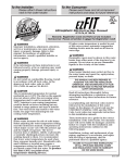
To the Installer:
To the Consumer:
Please attach these instructions
next to the water heater.
Please read these and all component
instructions and keep for future reference.
Solar Storage Tank with Electric Backup
Instruction Manual
Warranty, Registration Card and Parts List are included.
Homeowner: Please remember to return the Registration Card!
INSTALLER RESPONSIBILITIES
䊱
! WARNING
Improper installation, adjustment, alteration,
service or maintenance can cause serious
injury or property damage. Refer to this
manual. For assistance or additional
information, consult a qualified installer or
service agency.
䊱
! CAUTION
The recommended temperature for normal
residential use is 120°F. The dial on the
aquastat does not always reflect the outcoming water temperature, which could
occasionally exceed 120°F. The variation in outcoming temperature could be based on factors
including but not limited to usage patterns and
type of installation. Test your water at the tap
nearest to the water heater.
䊱
! WARNING
Hotter water increases the risk of scald injury.
Before adjusting the water temperature setting,
read this instruction manual. Temperatures at
which injury occurs vary with the person’s age
and the length of exposure.
The slower reaction time of children, elderly,
and physically or mentally challenged persons
increases the scalding hazard to them. It is
recommended that lower water temperatures
be used where these exposure hazards exist.
Such households may require a temperature
setting less than 120°F to prevent accidental
contact with hot water.
To lower water temperature use point-of-use
temperature limiting devices.
䊱
! WARNING
Water heater blankets are not recommended
and will void the warranty.
THIS MANUAL HAS BEEN PREPARED
TO ACQUAINT YOU WITH THE INSTALLATION,
OPERATION, AND MAINTENANCE OF
YOUR WATER HEATER AND TO PROVIDE
IMPORTANT SAFETY INFORMATION.
23570
Please read all instructions thoroughly before
installing or placing the heater into service.
This unit must be installed by licensed or
authorized installers, or technical personnel
that service water heating equipment. The
heater must be installed in accordance with all
local codes and ordinances.
These instructions are a guide for the correct
installation of the water heater. The
manufacturer will not be liable for damages
caused by failure to comply with the installation
and operating instructions outlined on the
following pages.
䊱
! CAUTION
The recommended water temperature setting for
normal residential use is 120°F/49°C.
HANDLING
Before uncrating, check for shipping damage.
Report any damage to your carrier. Note damage
on bill of lading or delivery receipt and file a
claim.
FAILURE TO FOLLOW THESE INSTRUCTIONS
OR ALL APPLICABLE BUILDING CODES AND
REGULATIONS VOIDS THE WARRANTY
ON THIS WATER HEATER.
Read all instructions thoroughly before
attempting installation or operation of your
water heater. Keep these instructions for future
reference.
Local plumbing and electrical codes must be
followed in the installation of this water
heater. In the absence of a local code use the
UNIFORM PLUMBING CODE and the NFPA
Code. Local codes may supersede instructions
in this installation manual.
These instructions are a guide for the correct
installation of the water heater. The
manufacturer will not be liable for damages
caused by failure to comply with the
installation and operating instructions
outlined on the following pages.
Rev 2 1/09
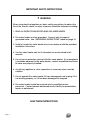
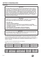
IMPORTANT SAFETY INSTRUCTIONS
䊱
!
WARNING
When using electrical appliances, basic safety precautions to reduce the
risk of fire, electric shock, or injury to persons should be followed, including:
1. READ ALL INSTRUCTIONS BEFORE USING THIS WATER HEATER.
2. This water heater must be grounded. Connect only to properly
grounded outlet. See “GROUNDING INSTRUCTIONS” found on page 12.
3. Install or locate this water heater only in accordance with the provided
installation instructions.
4. Use this water heater only for its intended use as described in this
manual.
5. Do not use an extension cord set with this water heater. If no receptacle
is available adjacent to the water heater, contact a qualified electrician
to have one properly installed.
6. As with any appliance, close supervision is necessary when used by
children.
7. Do not operate this water heater if it has a damaged cord or plug, if it is
not working properly, or if it has been damaged or dropped.
8. This water heater should be serviced only by qualified service
personnel. Contact nearest authorized service facility for examination,
repair, or adjustment.
SAVE THESE INSTRUCTIONS
Page 2
TABLE OF CONTENTS
Section I: Specifications . . . . . . . . . . . . . . . . . . . . . . . . . . . . . . . . . . . . . . . . . . . . . 4
Section II: General Information . . . . . . . . . . . . . . . . . . . . . . . . . . . . . . . . . . . . . . . 5
Section III: Pre-Installation . . . . . . . . . . . . . . . . . . . . . . . . . . . . . . . . . . . . . . . . . . . 8
Section IV: Installation . . . . . . . . . . . . . . . . . . . . . . . . . . . . . . . . . . . . . . . . . . . . . . 9
Section V: Operation . . . . . . . . . . . . . . . . . . . . . . . . . . . . . . . . . . . . . . . . . . . . . . . 13
Section VI: Maintenance . . . . . . . . . . . . . . . . . . . . . . . . . . . . . . . . . . . . . . . . . . . . 14
Section VII: Troubleshooting . . . . . . . . . . . . . . . . . . . . . . . . . . . . . . . . . . . . . . . . . 15
Section VIII: Parts List . . . . . . . . . . . . . . . . . . . . . . . . . . . . . . . . . . . . . . . . . . . . . . 16
Section IX: Warranty . . . . . . . . . . . . . . . . . . . . . . . . . . . . . . . . . . . . . . . . . . . . . . . 17
Page 3
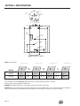
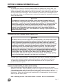
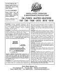
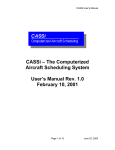
SECTION I: SPECIFICATIONS
ANODE
HOT OUT
(3/4" NPT)
COLD IN
(3/4" NPT)
FROM SOLAR
(3/4" NPT)
TO SOLAR
(3/4" NPT)
3/4" NPT
Port
T&P RELIEF
VALVE
Electric
Heating
Assembly
FROM SOLAR
(3/4" NPT)
B
D
C
Sensor
Immersion
Well
E
TO SOLAR
(3/4" NPT)
F
G
A
Figure 1: 80STE, 119STE
B
C
D
F
G
80STE
24´´
64´´
57 1⁄8´
57 1⁄8´
31 1⁄2´
19 1⁄4´
6 1⁄2´
119STE
28´´
65´´
57 3⁄4´
57 3⁄4´
33 3⁄4´
16 1⁄4´
8 3⁄4´
E
Model
A
Table 1: Dimensions
Foam insulation standard. Pressures, all: Test pressure = 300 PSI; Working pressure = 150 PSI
Electrical rating (where applicable): 4.5KW, 240V
WARNING: Installation should be in accordance with all national and/or local codes.
CAUTION: The recommended water temperature setting for normal residential use is 120°F. Bock recommends a tempering
valve or anti-scald valve be installed and used according to the manufacturer's directions to prevent scalding.
Page 4
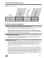
SECTION I: SPECIFICATIONS (cont.)
S ta
n
Rat dby Lo
ing
(°F/ ss
h r)
Model
Act
u
Volu al Tank
me
(gal
)
Elec
Firs tric He
a
t
(gal Hour R ting
)
atin
g
Table 2: Capacity & Performance
80STE
75
40
0.8
119STE
110
50
1.2
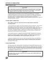
SECTION II: GENERAL INFORMATION
SOLAR STORAGE TANK WITH ELECTRIC BACKUP FUNCTION
The solar storage tank is designed to store water that has been directly heated in a solar panel
or indirectly heated by a solar panel through an external heat exchanger.
During periods of water flow through the storage tank, hot water is drawn from the top of
the tank and cold water is delivered to the bottom of the tank (by a diptube or bottom inlet).
If the hot water demand should exceed the solar heat output, the heating element thermostat
will activate the electrical heating element for backup heat.
WATER TREATMENT/FILTRATION
In areas where poor water conditions are suspected (i.e. lime, iron, and other minerals), it is
essential that the water be tested and appropriate action taken to prevent damage to the
indirect heater and ensure the quality of the water.
TEMPERATURE CONTROL
A solar controller (not provided) shall be used in conjunction with the solar storage tank to
run all solar components in the heating system. The solar controller will be connected to two
thermistors that monitor lower and upper tank temperature. In some cases, only one
thermistor (near the bottom of the tank) will be used. The proper temperature setting for
domestic hot water use is 120°F/49°C.
The solar storage tank is equipped with a backup electrical heating element and adjustable
thermostat. The thermostat is located behind the access cover on the side of the water heater.
If the solar system cannot satisfy the user demand, the electric element will energize and heat
the water until the thermostat is satisfied. An ECO (electrical cut-off) is included as part of
the temperature control and is designed to cut off power to the heating element in the event
the water in the tank reaches 180°F. The ECO is a safety feature on the water heater and
cannot be adjusted. In the event that the ECO opens, the control must be manually reset with
the stored water temperature below 180°F.
Page 5
SECTION II: GENERAL INFORMATION (cont.)
The thermostat is factory set at 120°F. See Table 6 for thermostat letter and temperature
relationships. If hotter water is required a tempering device or anti-scald device must be
installed at the domestic hot water outlet of the heater or at the point of use. Table 3 details
the approximate relationship of water temperature and time with regard to scald injury. It is
important for the user to understand the necessity of tempering or anti-scald devices when
using hotter water in domestic water heating systems.
䊱
! CAUTION: Hot water in excess of 120°F can cause scalding!
Bock recommends a tempering valve or anti-scald valve be installed and used according to
the manufacturer’s directions to prevent scalding. Many state and local codes now require
installation of these devices. The tempering valve or anti-scald valve will ensure potable
water temperatures at the desired set point with a higher degree of accuracy.
Table 3: Scald Temperature/Time Relationships
APPROXIMATE
TEMPERATURE/TIME
RELATIONSHIPS TO
SCALDING
Page 6
120°F
More than 5 minutes
125°F
1 1⁄2 to 2 minutes
130°F
About 30 seconds
135°F
About 10 seconds
140°F
Less than 5 seconds
145°F
Less than 3 seconds
150°F
About 1 1⁄2 seconds
155°F
About 1 second
SECTION II: GENERAL INFORMATION (cont.)
ANODE RODS
The anode rod is used as a sacrificial element within the volume of the storage tank. The
purpose of the magnesium anode rod is to protect the inside of the tank against corrosion.
Anode rods should be inspected twice in the first year and at least yearly once a time interval
for inspection has been developed. Water conditions can influence the consumption rate of
the anode rods. Please see the Maintenance section of this manual for instructions on how to
change the anode rods.
䊱
! CAUTION
Hydrogen gas is produced in a hot water system served by the heater that has not
been used for a long period of time (2 weeks or more). Hydrogen gas is extremely
flammable. To reduce the risk of injury under these conditions, it is recommended that
the hot water faucet be opened for several minutes at the kitchen sink before using
any electrical appliance connected to the hot water system. When hydrogen is
present, there will probably be an unusual sound such as air escaping through the
pipe as the water begins to flow. There should be no smoking or open flame near the
faucet at the time it is open.
TEMPERATURE AND PRESSURE RELIEF VALVE (T&P)
䊱
! CAUTION
To reduce the risk of excessive pressures and temperatures in this water heater, install
temperature and pressure protective equipment required by local codes and no less
than a combination temperature and pressure relief valve certified by a nationally
recognized testing laboratory that maintains periodic inspection of production of listed
equipment or materials, as meeting the requirements for Relief Valves and Automatic
Gas Shutoff Devices for Hot Water Supply Systems, ANSI Z21.22. This valve must be
marked with a maximum set pressure not to exceed the marked maximum working
pressure of the water heater. Install the valve in an opening provided and marked for
this purpose in the water heater, and orient it or provide tubing so that any discharge
from the valve exits only within 6 inches above, or at any distance below, the
structural floor, and does not contact any live electrical part. The discharge opening
must not be blocked or reduced in size under any circumstances.
The T&P valve is factory installed. A discharge drain tube must be installed (responsibility
of the installer) and shall terminate plain, not threaded, 6 inches above the floor drain.
The drain tube material must be approved for temperatures of 120°F or greater and a
pressure of 150 PSI or greater.
BACKFLOW PREVENTER (CLOSED LOOP SYSTEM)
Some local municipal codes and ordinances require the use of these devices on potable
(domestic) water lines. Where backflow preventers are required, it will be necessary to install
a thermal expansion tank (designed for used with potable water) in order to prevent
pressure build up in the storage tank and associated piping, which could cause the T&P valve
to discharge. Follow the expansion tank manufacturer’s recommendations when selecting a
tank for your hot water system.
Note: Working pressure of the water heater is 150 PSI. Do not exceed 150 PSI.
Page 7
SECTION III: PRE-INSTALLATION
LOCATION
䊱
! CAUTION
This water heater must be located in an area where leakage of the tank, water line
connections, or the temperature and pressure relief valve will not result in damage to
the area adjacent to the water heater or to lower floors of the structure. When such
location cannot be avoided, a suitable drain pan must be installed under the water
heater. The drain pan depth must be suitable for draining and collecting water. The
drain pan can be purchased from your plumbing professional. The drain pan must be
piped to an adequate drain and all drain piping must be at least 0.75” in diameter
and pitched for proper drainage.
䊱
! CAUTION
DO NOT store or use gasoline or other flammable, combustible, or corrosive vapors
and/or liquids in the vicinity of the water heater or any other appliance.
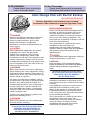
IF YOU SMELL GAS:
• DO NOT try to light any appliance.
• DO NOT touch any electric switch; do not use any telephone in your building.
• Immediately call your gas supplier from a telephone in another building. Follow your
gas supplier’s instructions.
• If you cannot reach your gas supplier, call the fire department.
DO NOT OPERATE THE APPLIANCE UNTIL THE LEAKAGE IS CORRECTED!
䊱
! CAUTION
Do not drop water heater or lay heater down on its side. Move the water heater into
position by sliding or using an appropriately sized hand truck.
The solar storage tank must be installed indoors. Locate the storage tank as close as practical
to the solar heating system and leave sufficient clearances for servicing. The entire solar
heating system should be located as close as possible to points of hot water use for the fastest
delivery of hot water. This product may be installed on combustible flooring. DO NOT
install on carpeting.
See Tables 4 and 5 for combustible and service clearances.
Table 4: Clearance from Combustible Materials
Top
Sides
Front
Rear
0´´
0´´
0´´
0´´
Table 5: Recommended Service Clearances
Page 8
Top
Sides (non-piping)
Side (T&P Relief Valve)
Front
Rear
12´´
4´´
6´´
16´´
0´´
SECTION IV: INSTALLATION
WATER CONNECTIONS
䊱
! CAUTION
This water heater incorporates fittings that contain a nonmetallic lining. DO NOT apply
heat to these fittings when making sweat connections to the heater. Sweat tubing to
an adapter before securing adapter to any fittings on water heaters.
ALL PIPING SHOULD CONFORM TO LOCAL CODES AND ORDINANCES. It is highly
recommended that unions and shut-off valves are installed at the potable water and solar
connections to allow for isolation and/or movement during service. Installing a union on
the potable outlet is of particular importance to facilitate replacement of the hot
outlet/anode nipple. In addition, all piping should be adequately insulated with an approved
material to minimize heat loss.
POTABLE WATER CONNECTIONS
THE STORAGE TANK MUST BE FILLED WITH WATER BEFORE CONNECTING
ELECTRIC POWER.
1) Close the main water supply valve before continuing with the installation. After the main
water supply is shut-off, relieve the water line pressure by opening a faucet. Once the
pressure has been relieved, close the faucet. The “Cold” and “Hot” potable water connections
are labeled on the water heater. Install a union and shut-off valve at both potable water
connections. All piping should be ¾” diameter new copper or larger. A tempering valve or
anti-scald valve should be installed at the potable water outlet and used according to the
manufacturer’s specifications to prevent scalding.
2) If a backflow preventer is required in the cold water supply, a properly sized expansion
tank must be installed to control thermal expansion. Do not operate the water heater in a
closed system without installing a thermal expansion tank. Follow the expansion tank
manufacturer’s recommendations when selecting a tank for your system.
3) Following installation of the water lines, open the main water supply valve and fill the
water heater. Open several hot water faucets to relieve air from the system. After water is
flowing through the faucets and the system is void of air, close the faucets and check for
water leaks in the system.
SOLAR CONNECTIONS
The solar storage tank is designed with “TO SOLAR” and “FROM SOLAR” connections at the
top and side of the tank. For simplicity, solar connections are shown at the side of the tank in
Figures 2 and 3. The “TO SOLAR” connection at the top of the tank incorporates a dip tube to
draw cold water from the bottom of the tank. It is recommended to install a union and shutoff valve at each solar connection. All pipe and fittings between the solar system and storage
tank should be ¾” diameter or larger.
䊱
! CAUTION
This product does not contain an internal heat exchanger. ONLY POTABLE WATER SHALL
ENTER THE STORAGE TANK.
Page 9
SECTION IV: INSTALLATION (cont.)
If the solar storage tank is installed in a system that utilizes a heat transfer medium
other than potable water, a separate (external) heat exchanger must be installed.
The external heat exchanger must be constructed such that if a failure occurs, it will not
result in contamination of the potable water. For a solar system piping diagram that
incorporates an external heat exchanger, see Figure 3.
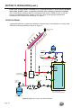
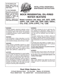
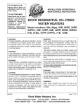
PIPING DIAGRAMS
A piping diagram for a typical solar domestic water heating system based on a storage tank
with electric heating backup is shown in Figure 2.
so
la
rc
ol
le
ct
or
a
rra
y
air vent w/ shut
off valve
cold water
hot water
anti-scald valve
electric
heating
element
circulator w/
isolation flanges
pressure
relief
valve
solar
controller
air separator
fill/purge valves
solar storage tank
w/ electric heating element
expansion tank
Figure 2: Single tank system with electric backup
Page 10
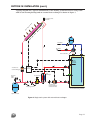
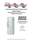
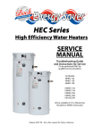
SECTION IV: INSTALLATION (cont.)
A piping diagram for a typical solar domestic water heating system based on a storage tank
with electric heating backup and an external heat exchanger is shown in Figure 3.
so
la
r
co
lle
c
to
ra
rra
y
air vent w/ shut
off valve
cold water
hot water
anti-scald valve
electric
heating
element
circulator w/
isolation flanges
pressure
relief
valve
solar
controller
air separator
fill/purge valves
heat
exchanger
circulator w/
isolation flanges
and check valve
solar storage tank
w/ electric heating element
expansion tank
Figure 3: Single tank system with external heat exchanger
Page 11
SECTION IV: INSTALLATION (cont.)
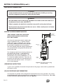
ELECTRICAL CONNECTIONS
䊱
! DANGER
Confirm that all electrical connections are unpowered before installing or servicing
electrical components/connections within the water heater.
䊱
! WARNING
The water heater must be electrically grounded in accordance with local codes or, in
the absence of local codes, with NFPA 70.
Failure to properly wire electrical connections may result in serious physical harm.
Electrical power may be from more than one source. Make sure all power is off before
attempting any electrical work.
ELECTRIC HEATING ELEMENT (BACKUP)
BRANCH CIRCUIT
TO ELECTRICAL
DISTRIBUTION PANEL
240 V
THE STORAGE TANK MUST BE FILLED
WITH WATER BEFORE CONNECTING
ELECTRIC POWER.
G
L1
GROUNDING INSTRUCTIONS
R
BK
JUNCTION BOX
3
RESET
2
4
1
2
R
The thermostat and electric heating element are
pre-wired at the factory. A junction box is
located at the top of the water heater. The
junction box cover will accommodate a ½” or
¾” electrical conduit connector. Two wires are
located in the junction box (red and black) for
connection to the branch circuit. See Figure 4
for a wiring diagram.
1
THERMOSTAT
& ECO
BK
All electrical connections must be made with
copper conductors only. A separate branch
circuit with copper conductors, over-current
protection, and means for disconnection must
be provided by qualified service personnel.
The total wattage load and voltage requirements
are specified on the rating label located on the
front of the tank.
L2
HEATING
ELEMENT
Figure 4: Thermostat and Heating
Element Wiring
A green screw (ground) is located in the junction box for proper connection to ground from
the branch circuit.
SOLAR CONTROLLER AND THERMISTORS
Two locations for potable water temperature measurement have been provided. The factory
installed immersion wells are designed to accommodate insertion of a thermistor. The solar
system controller and thermistors are not supplied.
Page 12
SECTION V: OPERATION
INITIAL START-UP
Reference the solar collector installation instructions for proper start-up of the solar collector.
Be sure that fluid flow in the solar system is established.
HEATING OPERATIONS
Condition 1: The minimum temperature difference (for heat transfer) between the potable
water at the bottom of the tank and the solar collector is sensed by the solar controller. In
addition, the tank temperature is below the maximum tank temperature setpoint (on solar
control).
Action 1: The solar controller energizes a pump to flow fluid through the solar
collector and storage tank. Potable water is circulated until the temperature
difference is reduced to a desired value or the maximum tank temperature has been
reached.
Condition 2: The heating element thermostat senses that the potable water temperature in
the upper area of the tank drops below the thermostat set-point.
Action 2: The heating element is energized and heats the potable water to the setpoint temperature, at which point the element is de-energized.
THERMOSTAT TEMPERATURE ADJUSTMENT
䊱
! CAUTION
The temperature setting on the heating element thermostat shall not exceed 160°F.
Likewise, the solar controller potable water temperature setting shall not exceed 160°F.
Install a tempering valve or anti-scald mixing valve at the outlet of the storage tank to
ensure greater control over water temperatures at the point of use.
䊱
! CAUTION
Turn off all power to the water heater before adjusting the heating element thermostat.
The heating element thermostat is factory adjusted to 120°F (“HOT” indicator setting). If
thermostat adjustment is necessary, disconnect all power to the storage tank and solar
collector. Remove the access cover on the side of the storage tank and remove the foam dam
insert to expose the thermostat and heating element. The temperature knob can be adjusted
with a screwdriver to a minimum temperature of 110°F and a maximum temperature of 160°F
(labeled “VERY HOT”). See Table 6 for a listing of indicator setting and temperature
relationships.
Table 6: Thermostat Temperature Settings
Indicator Setting
Temperature (°F)
• (min)
HOT
A
B
C
VERY HOT
110
120
130
140
150
160
Page 13
SECTION V: OPERATION (cont.)
䊱
! CAUTION
Hot water in excess of 120°F can cause scalding! The temperature at which injury
occurs varies with the person’s age and the time of exposure. The slower response
time of disabled persons increases the hazards to them. NEVER allow small children to
use a hot water tap. NEVER leave a child or disabled person unattended in a bathtub
or shower.
Replace the foam dam insert and access cover after adjusting/inspecting the thermostat.
If the thermostat temperature setting (or anti-scald mixing valve) was adjusted, check the
water temperature at a faucet. Flow enough water through the faucet to ensure that the
faucet temperature reflects the tank temperature. Adjust the thermostat or mixing valve
setting as necessary. Adjusting the thermostat setting (lower or higher) will not
immediately affect the water temperature at the faucet. Flow a sufficient amount of water
or allow a heat-up cycle to complete before making further adjustments.
SECTION VI: MAINTENANCE
WATER PIPING
On an annual basis, all piping should be checked for leakage at joints, shut-off valves, and
unions.
T&P RELIEF VALVE
On an annual basis, the temperature and pressure relief valve should be checked for proper
operation. First, attach a drain line to the valve to direct the water discharge to an open
drain. This is very important because the temperature of the discharge could be very hot.
Second, lift the lever at the end of the valve several times. The valve should operate freely
and return to its original position properly. If water does not flow out of the valve, remove
and inspect for corrosion or obstructions. Replace with a new valve if necessary. Do not
repair the faulty valve as this may cause improper operation.
ANODE RODS
Anode rods should be inspected twice in the first year and at least yearly once a time interval
for inspection has been developed. It is recommended to check the rod(s) six months after
the heater is installed. If the anode rod had reduced in size by two-thirds of its original
diameter of 3/4” or shows signs of pitting, it is time for replacement. Take the following
steps when changing the anode rod(s):
1. Shut off water supply.
2. Open any faucet to relieve tank pressure.
3. Remove caps on water heater top; push insulation aside.
4. Use a 1 1/16” six-sided socket wrench and a breaker bar. Snap hard to break the anode
rod seal.
5. Remove rod(s) and replace with new rod(s).
6. Turn water supply back on and leave faucet open until air is out of line.
7. Turn faucet off and check that new rod(s) doesn’t leak.
8. Snap caps back into place.
Page 14
SECTION VI: MAINTENANCE (cont.)
FLUSH THE TANK
The solar storage tank is glass lined. Elements in the water such as lime, iron and other
minerals may accumulate in the tank. It is recommended that the tank be drained and
flushed thoroughly once a year to prevent buildup.
SOLAR CONTROLLER AND COLLECTOR PANELS
The solar controller and collector panel manufacturer may have a recommended
maintenance procedure. Refer to the instruction manual that was received with the solar
equipment.
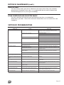
SECTION VII: TROUBLESHOOTING
PROBLEM
No hot water at faucet
CAUSE
ECO on thermostat tripped
Circulator does not operate
SOLUTION
Determine cause of ECO trip (solar heat or electric
element). Correct or replace as necessary. Reset
thermostat (depress red button).
Check power supply
Replace as necessary
Check solar controller
Improper thermostat setting
Turn thermostat to safe temperature setting
Electrical problem (relay, wiring, etc.)
Check fuse and replace
Check circuit breaker and reset (if applicable)
Check power supply
Water at faucet too hot
Insufficient hot water
Scale, hard white particles from
faucets, popping sound from tank
Thermostat set too high
Lower thermostat setting to safe level
Tempering valve not properly set or defective
Check manufacturers instructions
Thermostat set too low
Raise thermostat setting to safe level. See Section V
Undersized solar collectors
Calculate proper collector surface area, orientation, and
available sunlight.
Peak use of hot water is greater than tank
storage capacity
Determine peak usage, compare to tank capacity, and
add additional storage (storage tank) if necessary
Faulty tank thermostat
Replace thermostat
Lime, water hardness above 7 grains-120ppm Water treatment; softener; etc.
Rust staining; bad taste and odor in Iron/minerals in water supply
water
Filtration
Rotten egg odor
Hydrogen Sulfide
Flush tank with chlorine solution and install aluminum
anode rod(s)
Air from hot water fixture
Electrolysis or air introduced by water supply
Properly ground heater & replace anode rod(s). Check
well pump system.
Reduction in recovery
Dip tube broken or compromised by high
chlorine in water
Replace dip tube
Inlet/Outlet fitting corrosion
Galvanic corrosion of dissimilar metals
Install dielectric unions
T&P Valve dripping water
Excessive water pressure (above 150 psi)
Check incoming water supply pressure; closed loop
system requires expansion tank
T&P gushing water
Excessive water temp. (above 210 °F)
Adjust or replace thermostat and T&P valve
Page 15
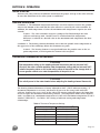
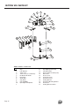
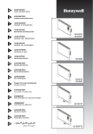
SECTION VIII: PARTS LIST
6
7
8
5
9
6
10
4
11
3
10
1
2
2
12
19 20 21
15 16 17
2
18
2
1
13
2
2
14
1
Table 7: 80STE, 119STE Parts
11
22
33
44
5
5
6
6
7
87
98
9
10
10
Page 16
Part Description
11
11
12
12
13
13
14
14
15
15
16
16
17
17
18
18
19
19
20
20
21
21
Plug
Plug
Leak
Leak Detector
Detector
J-Box
J-Box Cover
Cover
J-Box
J-Box Cover
Cover(w/
(w/conduit
conduithole)
hole)
Hot Outlet with Anode
Hot Outlet with Anode
Finish Ring
Pipe Nipple (plastic-lined)
Anode Rod
Finish
Ring
Cap
(blank)
Pipe
Nipple
with Diptube
Cap (“ANODE”)
Cap
(blank)
Pipe Nipple with Diptube
Cap ("ANODE")
Pipe Nipple
Anode
Rod (plastic-lined)
T&P
Relief
T&P Relief Valve
Valve
Sensor Immersion
Sensor
ImmersionWell
Well(solar)
(solar)
Drain Valve
Drain
Valve
Access Cover
Access Cover
Foam Dam Cover
Foam Dam Cover
Thermostat Cover
Thermostat
Cover
Heating Element
Heating
Element
Thermostat Mounting Bracket
Thermostat
Thermostat Mounting Bracket
Thermostat
Heating Element Gasket
Heating Element Gasket
SECTION IX: WARRANTY
LIMITED WARRANTY FOR SOLAR WATER HEATER
Bock Water Heaters, Inc.
110 S. Dickinson Street
Madison, WI 53703
Phone: 608-257-2225
What Does This Limited Warranty Cover?
This limited warranty applies only to the original consumer purchaser.
For water heaters installed in single family dwellings for residential use:
General Defects and Malfunctions: This warranty covers defections and malfunctions in your
new water heater for a period of one year from the original installation date. We will repair or
replace, at our option, any defective or malfunctioning component of the water heater. This
limited warranty will terminate if you sell or otherwise transfer the water heater, or the water
heater is installed at a location different from its original installation location.
Tank and Heat Exchanger (indirect coil only): We also warrant that the tank and heat
exchanger will not leak due to defective materials or workmanship for six years from the date
of original installation or from date of manufacture in the event the Limited Warranty
Registration Card was not completed and returned to manufacturer. If the tank and heat
exchanger is leaking and we have verified that the leak is due to a defect in materials and
workmanship, we will replace the tank with a tank that is the nearest Bock model available at
the time of replacement. If a replacement tank is provided, it will remain warranted under this
section as if it were the original tank. For example, if we send you a replacement tank under
this limited warranty two years after the original installation date, then the replacement tank
will remain warranted for the remaining four years after the original installation date.
For all other water heaters, such as commercial use:
General Defects and Malfunctions: This warranty covers defections and malfunctions in your
new water heater for a period of one year from the original installation date. We will repair or
replace, at our option, any defective or malfunctioning component of the water heater. This
warranty lasts for one year. Coverage terminates if you sell or otherwise transfer the water
heater, or the water heater is installed in a different location.
Tank and Heat Exchanger (indirect coil only): We also warrant that the tank and heat
exchanger will not leak due to defective materials or workmanship for three years from the date
of original installation or from date of manufacture in the event the Limited Warranty
Registration Card was not completed and returned to manufacturer. If the tank and heat
exchanger is leaking and we have verified that the leak is due to a defect in materials and
workmanship, we will replace the tank with a tank that is the nearest Bock model available at
the time of replacement. If a replacement tank is provided, it will remain warranted under this
section as if it were the original tank. For example, if we send you a replacement tank under
this limited warranty two years after the original installation date, then the replacement tank
will remain warranted for the remaining one year after the original installation date.
Page 17
How Do You Get Service Under the Limited Warranty?
In order to be eligible for service under this warranty you MUST return the warranty
registration card attached below within 30 days of purchasing the water heater. You may also
register your water heater online at www.bockwaterheaters.com.
You must have a copy of the original sales receipt at the time you request service.
To get service under this limited warranty you should contact either the dealer or installer. If
dealer or installer is unknown you can contact us via e-mail at www.bockwaterheaters.com. or
call us Monday through Friday between the hours of 8 o’clock a.m. to 5 o’clock p.m. Central
Time at the following number: 1-608-257-2225.
You can also write us at the following address:
Bock Water Heaters, Inc.
Warranty Support Group
110 S. Dickinson Street
Madison, WI 53703
We will respond not later than ten days after we have received your request for service.
What Does This Limited Warranty NOT Cover?
This limited warranty does not cover water heaters that are or were:
a.
Incorrectly installed, especially where the installation violates state or local plumbing,
housing or building codes.
b.
Operated at inappropriate settings, excessive pressures or temperatures.
c.
Exposed to adverse local conditions and specifically sediment or lime precipitation in
the tank or corrosive elements in the atmosphere or unacceptable water quality.
d.
Installed outside the United States or Canada.
e.
Accidentally damaged.
Also, we will not cover the following charges, costs and losses:
a.
Any freight or delivery charges.
b.
Any removal or installation charges.
c.
Charges to return the water heater or part to the manufacturer.
d.
Water damage, loss or damage to property, inconvenience or loss of use.
Page 18
What Will Void the Limited Warranty?
If you do any of the following, you will void this limited warranty:
a.
Fail to return the warranty registration card within 30 days.
b.
Fail to retain an original copy of your sales receipt.
c.
Fail to retain the actual rating plate from the water heater.
d.
Alter or remove the serial number.
e.
Transfer or sell the water heater.
f.
Remove the water heater from its original location and install it somewhere else
g.
Fail to follow the care and maintenance instructions provided with the water heater.
h.
Remove the anode rods.
i.
Fail to inspect and replace the anode rods (you must retain and present your paid
receipts as proof of anode rod replacement).
How Does State Law Relate to this Limited Warranty?
This is a limited warranty. WE MAKE NO OTHER EXPRESS WARRANTIES WITH RESPECT TO
THIS WATER HEATER. We will not assume, nor authorize any person to assume for us any other
liability in connection with the sale or operation of this water heater. ANY IMPLIED
WARRANTIES, INCLUDING MECHANTABILITY OR FITNESS FOR A PARTICULAR
APPLICATION, IMPOSED ON THIS SALE UNDER THE LAWS OF THE STATE OF SALE ARE
LIMITED TO ONE YEAR. This warranty gives you specific legal rights, and you may also have
other rights which vary from state to state. Some states do not allow limitations on how long
an implied warranty lasts, so the above limitation may not apply to you.
WE WILL NOT BE RESPONSIBLE FOR WATER DAMAGE, LOSS OF USE OF THE UNIT,
INCONVENIENCE, LOSS OR DAMAGE TO PERSONAL PROPERTY, WHETHER DIRECT OR
INDIRECT, AND WHETHER ARISING IN CONTACT OR TORT. Some states do not allow the
exclusion of incidental or consequential damages, so the above exclusion may not apply to you.
Page 19
Bock Water Heaters, Inc. • 110 South Dickinson Street • Madison, WI 53703
Telephone: 608-257-2225 • Fax: 608-257-5304
www.bockwaterheaters.com