1
ACTentry A10 Operating and Installation Instructions
ACTentry A10 Operation
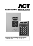
The ACTentry A10 is a simple, easy-to-use access control unit combining digital keypad and door-entry
telephone technologies. The ACTentry A10 Door Entry Panel incorporates a call button for the Door
Intercom Handset, Speech Unit (grill, microphone and speaker) and ACT 10 Digital Keypad.
For residents or legitimate personnel, their PIN code, entered on the digital keypad, will unlock the door
for a preset time. The unit supports a maximum of 10 PIN codes. Visitors can press the call button to
request entry, which creates a call to a Door Intercom Handset located within the building. The operator
can speak to the visitor before granting or denying access
ACTentry A10 Installation
Read carefully all the information presented in this section and then install the ACTentryA10 in
accordance with the wiring diagram below. The door entry panel is supplied with either a surface or
shelteredlocation.
Cable Requirements:
For optimum speech clarity, it is strongly recommended that the ACTentry A10 system is installed using
twisted-pair telephone cable (eg type CW1308). Use one of the pairs for the R&O connection between
the speech unit and the telephone/intercom handset.
Using CW1308 Cabling:
Connections
Phone
Exit
PSU
Number of Cores
5
2
2
Core diameter
0.5mm
0.5mm
0.5mm
Max. Cable Length
100 metres
100 metres
15metres
The ACTentry A10 may be installed also with 2 CAT5 cables. Use one cable for the PSU. Combine 4
cores for positive and 4 cores for negative. Use the other cable for the phone and the exit button.
Using CAT 5 Cabling:
Connections
Phone
Exit
PSU
Number of Cores
5
2
4 for positive, 4 for negative
Max. Cable Length
100 metres
100 metres
100 metres
Speech Adjustment
The speech unit has two adjustable potentiometers for changing the speech levels:
Volume A: Speech level at the entrance panel
Volume B: Speech level at the telephone
5