1
Federal Communications Commission
(F.C.C) Statement
!"#
$
% "&# $
% $ '
! $ ( % )!
*
"#
&*
"#
+*
"#
,*
"$
#
)
-
$ $
)
$
( %
) % )
$ $%
% $ -)
% $ ) % $ $ $ !
.
&-
)
+
)
,/
.0
! /$ $ 1$)
Disclaimer
2 $ $ $$
2
$$$
3
%%
1 Trademarks and Remarks
4*3*% 5% 5 6% 5 7/ 4
% 2% $
0
' 2 $ $ 8777
' Canadian D.O.C. Statement
/
(
3
9) 1 9
) 9
)9/9)(9
9
) 3
Contents
&
: &
&* ;
+'
<
&4-=
&>$4 =
+4
7
+
!'6?> @
+&'A&@
!5?,
++:32
!-3?.-3?&
+,$32
!33 ,(
2
;
,*.&4.B$
!6;
,&C*(
!C*( <
*-
7
;C-&+
;C-
!*
2+<@ &+
;&CD* &,
Contents
<D* &;
<*$
!D &<
<&C
!D;&<
<+52>'6
!D5>&<
<,524
!D54"#&<
<4*
*
!D(' &=
=3'4-&7
=3-44 &7
=&:3-444 +
7'*$+&
73'-
!D<.D= ++
7&$
!D7++
7+'CA'
!D@"# ++
&44&+
&&*4*&
&+'
(-*&=
&,'
&&
&- &
&;4 *&&@
&<.- &&,
&=:* &&=
&7>E3 &&7
Contents
&@**.C &+@
&*F?/* &+&
&&?/5* &++
+*> +
+&*- +
++C *++
Chapter 1
Motherboard Description
Introduction
2$ G$
)
2$ $ - $ ) / - % H/ I
0-';7,A.;=;' % -*'%
'J--3? % . % . 'A
$% &=2$ &;2$ &2$ C% >
( $ $ (
* *$ +3 )$ '4 * %
-
2 $ 4*3*% 5 +/% 5 6%
5&@@@%6%*.&%57/%C6-A%*C6-A
/
Chapter 1
Motherboard Description
1 Motherboard Description
1.1 Features
1.1.1 Hardware
−
!! "#$% & ' (
!! )&! * +
* , +&
*-!
!
&!)!
− )&!-./0
− +
100..(23&4!,
− − !,'..(23/..(23! &!
!..(2354!! &
− !611.17161(485(('&!
− !!!8$("..9%
− !
'
:''''!3,/6(4*8$(
− ..(234!,
− ! *'
+' )
45;
− *&*',''
− <
-! =
- !!&'!
)
− <
-;>$?
&
Chapter 1
Motherboard Description
− )& "@17@%$# ! & 1* = 5$ 4! !!
"; %
− 1).=5=!'
!!!"; %
− 59' − !758
&&!-&)!
! (& 7A =! '
! '&A + ,'
& &!&)!
!
8($..1A=!'
!'&
!58,
*8;(
!+
&&!-&)!
!>4$'&
− −
−
−
−
− !=+,'>0B 8!-C'+
D5&!-
!"#
$%&'()
− 7)*
)
=!!!
− 8;#
'' =
− !!
!+!
=55 − ( !
' !
− 8
&)5=!
− − -
− 54!(
!,,
!8($
− &!
!&2!''
− &>=
,)7000&!
− . ! & . ' ! = ':& !
'
− 851;! !!,+!!
− ' *E/*(
+'! ,
+
Chapter 1
Motherboard Description
*( − −
−
−
−
−
''&
"% &
&F4&
"%
"%
&
"%
".%:&&
=!"%
!*!
!A0$*=5;
$&
! (=
&
!5,
&
!'!!"5% !1(!
! .0G4A /0G4A (4A 77(4 & 66(4 ,
&)!
&!-
!"#
− 8
,& :8 &
!=* !!''' &
$E/-
− 5'
!,
*!
1+
&=!+
=
− .=5;,
&!&
− 2!=
!&!
' )
&':
− &
& )0 )0 $E/ & ,
, !+ !
&&
$E/&H!,'' )&!
− > =
- = , &+ ':& & !
'! 4
&.E7! -!
− 2
&*
&4
! , <&*! 8; =: & '&
8!+
' =
− + & * 7 5A 7 8($A & 7 51; ! ! ,
&4
!
&(585
&*
− 2
&*
!!!&(!!!,+
' =
− 8*+
' !
&(585 ,
− ' !,*
&) ! , <&*! EA <&*! E6A
<&*!?
&<&*!000
&#
− ! = $5 "$&)
& & ,+
& *
5,
%
&+
"$(% *'
+'
− $5)0' − $()' ,
Chapter 1
Motherboard Description
− -+
&-! ,' $50
.!
!
− 5 =! - A * (
+' = "(% A &
−
−
−
−
−
−
−
−
−
−
−
−
−
−
51-+
! ! ' !!' !! & ! * !! &! *
,:=15=!! !A
&!! &&!-"!,,,%A
*
&*
'
*
- ( !! & * !
&!! &!
!&
!
; & 'A ' & +
! 'A
!71.=$5' '
?'
A&3A! A!! &A
&!)'&!
#=
&
&) *
!')'+**)
!!!
'
& !&
&,,
, &)&
!
8&
& !, *
&! =!A:
'&'+
&
A
&=-& 1!,!!'*
- ( & :
(5 !! , ,:= *
'
+''&!
; +
''
= !
&' !
& +
& ' - "% * &
'A '
'A
&,&
'
' :
'=
, * ' !!+!
2&-+! 51; &
-
+
+
− 4)
&5)!
25)' =
− + ) "&=*&!% &
5; * , !
& +
=
− =
&,, !
− 5+
&
!
!)! * )
&!
!4 !
− G=
&
&'!! ,
− $@'
Chapter 1
Motherboard Description
− .'@.0'"<:>%
$
)
− !
& !&!!*=!* '
!-*
− $#)0' − !&4
&$&&!!+"4$%'&"' :&
&&!!
1&
%
− !(2D7:'&,$8
&4$!+
+
− &! !
+=!
!,! #41!
− +)
&!
− ) !&*!
− *)"
&*-!%
&&
5;"=!%
− :)"
&*-!%*&
5;"6=!%
− 5+!&+,'
:''$#=!3
− !!1''
&!
− #
!$&&!!
="#$%
"%;)>4!
"%:,
!!
) +
=
".%> '!'
"7%5& &#$- ,!1$#15'
!
!!!
− <&*! E ; 9@8 & +
& <&*! E6 1 ?000
1<5??' &)! 1.1.2 Software
(
− $<$8+
F!,&45;
;
Chapter 1
Motherboard Description
− !,!
(#
− ;,,! +! ,'
, (8; ;1A <&*! ?A
<&*!000A<&*!.1E1E6A?)A?5@A;?5A
&
!
1.1.3 Attachments
− 288
=
− 88
=
− 4
="; %
− 8 , 58 1 9#$ 8)A 45; ,
! * A $&
8)
<
Chapter 1
Motherboard Description
1.2 Motherboard Installation
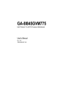
1.2.1 Layout of Motherboard
Model No.M6VCG
!"
#$
Socket 370
#
#
%$&
!
$
=
Chapter 1
Motherboard Description
1.3 Motherboard Connectors
A. Back panel I/O connectors
J. Front USB Connector (USB2)
B. AGP BUS Slot (AGP1)
K. Front Panel CONN. (PANEL1)
C. CPU Frequency Selection (JP1) L. CMOS Function Selection (JBAT1)
D. AMR Slot (AMR1)
M. System Fan connector (J5)
E. PCI BUS Slots (PCI1-4/5)
N. Ratio Selection (JFREQ1)
(Optional)
O. Wake On Modem (JWOM1) (Optional)
F. CD Audio-In connector (J7/J8)
P. Wake On LAN (JWOL1)
G. AUX Audio in Connector (J10)
Q. IDE Connectors (IDE1-2)
(Optional)
H. Telephony connector (J9)
I. ISA BUS Slots (SL1-4)
(Optional)
R. FDD connector (FDD1)
S. ATX Power connector (POWER1)
T. CPU Fan Connector (J6)
U. DIMMs (DIMM1-3)
7
Chapter 1
Motherboard Description
1.3.1 Front Panel Connectors : PANEL1
Pin
No.
Assignment
1
Speaker
2
NC
3
Ground
4
Function
NC
Pin
No.
Assignment
Function
14
+5V
VCC
Speaker
15
Ground
Ground
Connector
16
NC
NC
+5V
17
Sleep Switch
SMI
5
Power LED(+)
18
Ground
6
NC
19
NC
NC
7
Ground
20
HDD LED(-)
HDD
8
NC
No
21
HDD LED(+)
LED
9
NC
Function
22
+5V
10
Power Switch
ATX Power
23
NC
IrDA
11
Ground
Button
24
IRRX
Connector
12
Reset Switch
Reset
25
Ground
13
Ground
Button
26
IRTX
Power LED
@
Chapter 1
Motherboard Description
Chapter 1
Motherboard Description
-
$ ,,=
& ! - = !
& '=
& ! '
,
+
$ ,,=
& ! - = & '=
& ,
! - "=
& ,,=
&% )&! = &
,'
&+ * ; ,! * ' ! )&,
! -!&
&!=!!'
&&!
) ,'
&!=!!'
! = & ''
!* !
'
< !* ! !&A '=
& !! & ! ;
&.
!
=&
>8
*+*' !
*&
%+.
!
=&
>8 )&
)!
&
&
!=+
&,'*
&&)>8, A
58&)'!=&=
&
&&)
,
$,58$,
!,+&A,!
=
!,&,' =
&)!!
!
!A8$!A
& !!+
!,*
$*&)
< $( ! =& !!' 45;A & + !!'I! $(
&) ! &&A !!' ! "!
&=% '& , ,*+*
!
; , (5=
•
+&!!'
)!+45;
)',
•
&
&, 51;! !
, (5!*A*'!=
''
!'
&
Chapter 1
Motherboard Description
!+ (5 !* !&! !' (
+' 5 "(5% !!A * ''&
+! !' (
+' (&
"((%<' !! '&!,
=,! &+
& !)+ :
! "! ! '+ ,
:% ) + ' ! , -=
& '! ! )
!' !!'A (5 !* '! = !!& +
A -=
& '!'!=!&
&(
!
=&
, *!*!*'!
*4 +&,
!0'!!+
*! !*,,"''!&
&
'=
&% $ ! * !&! '! !! =, * ! *
+3
1,,!+
+
Chapter 1
Motherboard Description
1.3.2 ATX 20-pin Power Connector : POWER1
! ! ! * = =
& !+ $@ *
! A ,! ! ! (&' + <
- & , * ;,, ! & ! '=
& ! * ! ! !
*
,
A * '
! !!' * = !
* *!!&=
&
PIN
VOLTAGE
PIN
VOLTAGE
1
2
3
4
5
6
7
8
9
10
3.3 V
3.3 V
GND
5V
GND
5V
GND
PW_OK
5V_SB
12 V
11
12
13
14
15
16
17
18
19
20
3.3 V
-12 V
GND
PS_ON
GND
GND
GND
-5 V (Optional)
5V
5V
Warning: Since the motherboard has the instant power on function,
make sure that all components are installed properly before
inserting the power connector to ensure that no damage will be
done.
,
Chapter 1
Motherboard Description
1.3.3 Hard Disk Connectors : IDE1 / IDE2
'=
& ! .= & 5 58 )&! 5;
(&0J7A4!(
!A
&
8($..1,
5
!*288
!58" '
%
&58"!&
% K
,
& &!- &)!A 8;(A 0(4 "!)& , , 45;% &
&)!58 &58 !!! 58
& &!
= )&&
! ,! & &) !& *
! = & 58 58 (
!
&
)&)K'!,+!&
&&)58
)'&=!+L' &+
! 58 ! ! (
! & ) &) ,+
!!'
58!&&)!'!=!
!
)'&
1.3.4 Floppy Disk Connector : FDD1
'=
& )&!
!
&
&, &!-"8%
! !
.0GA /0GA (A 77( & 66( , &!- ! ! ! ! )&&, &)==
=!
Chapter 1
Motherboard Description
1.4 Back Panel Connectors
6
6<'
1.4.1 PS/2 Mouse / Keyboard Connector : CN1
'=
& )&!
!
&
&1'!1G=
&'85?
,
+
1'! K
+
1'!1G=
&&
! & &,
!*=*
;
Chapter 1
Motherboard Description
PS/2 Mouse / Keyboard Connectors
Pin
Signal Name
1
Data
2
No connect
3
Ground
4
+5 V (fused)
5
Clock
6
No connect
1.4.2 USB Connectors : USB1
'=
& )&! ,
+4&)!!
!-=
&A'!
& 4 &)! K + 4 8)! & !
USB1
Stacked USB Connectors
Pin
Signal Name
1
+5 V (fused)
2
USBP0- USBP1-
3
USBP0+ USBP1
4
Ground
Note: (1) Signal names in brackets (
)
are for USB port 1.
<
Chapter 1
Motherboard Description
Front Two USB Connector (USB2)
4
0
E
Pin
Signal Name
Pin
Signal Name
1
3
5
7
9
+5V
USBP2USBP2+
Ground
Ground
2
4
6
8
10
Ground
Ground
USBP3+
USBP3+5V
=
Chapter 1
Motherboard Description
1.5 Serial and Parallel Interface Ports
!!!''! &**!
!
& 4 !
,,
!*=: &!
/, ' (0*(1
!
,
! !''! ,& ! . !!''
! (A !A'&'!
& &)! = & !
!
! = !& ' *
' !!'5,*!
!,
!,
&&!-
!!'
=
' !&=!+
'
I!!
!
! ! !!' ! * E ' & ' !!'!
& !!&= &* $!
&E !
& !
A
!
E &
7
Chapter 1
Motherboard Description
+
!
=!&'
*
!A
&
=!!
=',
'
* &
+
',*+
+)!,,
E &!', !,'
=
!&*,++
!,*
+
'!*-*!
Signal
Name
DB9 PIN
DB25 PIN
DCD
Data Carrier Detect
1
8
RX
Receive Data
2
3
TX
Transmit Data
3
2
DTR
Data Terminal Ready
4
20
GND
Signal Ground
5
7
DSR
Data Set Ready
6
6
RTS
Request to Send
7
4
CTS
Clear to Send
8
5
RI
Ring Indicator
9
22
* !,!
&)!
=&
!
;,
&)! ! & B8C "8
'
'% & &) !
&B8C"8
''
! '%5,
'&'!&
' A,:
' A'&'!
&8
&' !
&
85!
!!
!!A !!
!
=&
!
++
5 !
! * * 8 &)! & +A ! ! ' & A ! &
& B? (&'C ! && '
-''
=**&)! !!=
< !+ !
''
=* &)!A =' '
! ' '
,
! ! ! , !+
! =+
''
*
&)
&'
,
!&!!
&@
Chapter 1
Motherboard Description
!+
!
''
5,
''
='
= !)& !+ '&'A +
= !!'& &) ! !+ 3
!+
! & &) ! ! !
=!)&=*+AA
&88 !+
*(
*!
!' &;(
&;(A! )
5,*!A*'!
!
=
&&&' !+ &*
& ! && :
! ";( !% *&=
&;(.
&;(7
< !+ !
! ''
* &)A = ! !!+;( '=
&):
' A,
&
!
=&' +!
!A '!
= !!+& ;( " ;(% & !
'! = !!+& ;( ";(%?*&)!
=
!!+&;( '!
)!*;( ?; !
! '
= !
& ' 2*)A '
* !
=!&!'
!
M5, ) !
& '&'A = , !!+ ;( '=
!
&=
!!+&
&)!!''
< !
+ &) ! ++ ! , !
A ! &
+! +
',&* !
)
=5'
=!!
') : ! &! ) !
! & - L' !+! L' !+! * &
* ;( & ! =
!!+& -+ : ! & * '
'!
-! )
+
;( !;
)' &!
, &)!!+
!
!A = ! ''
'! ! ! =
& A
=A
'
+5,' !!,
=
&
,E00
&
'&'!!,
=
&
,700*=
=!&'!!
+!
'
! ' &)! * ,' &,!+ '!,*
'
!
!
)!!
!+ '!
&
Chapter 1
Motherboard Description
,'2"
0
-!
A ,
!
)=!
&
&3&
&!&
!
&,,,
+ !!!'''!
&
! A !
'! :!)!&* ! !!'
!
A84"! =*%
, !*
==*
Signal
-Strobe
Data 0
Data 1
Data 2
Data 3
Data 4
Data 5
Data 6
Data 7
-Ack
Busy
Paper Empty
+Select
-Auto FDXT
-Error
-Init
-SLCTN
Ground
Ground
Ground
Ground
Ground
Ground
Ground
Ground
&&
Pin
1
2
3
4
5
6
7
8
9
10
11
12
13
14
15
16
17
18
19
20
21
22
23
24
25
Chapter 1
Motherboard Description
1.6 CPU Installation
1.6.1 CPU Installation Procedure : Socket 370
$$
2
7@ &
>
'
22
C 4
' .
C
+
&+
Chapter 1
Motherboard Description
1.6.2 CPU Jumper Settings
&,
Chapter 1
Motherboard Description
1.6.2.1 CPU Ratio Selection : JFREQ1
JFREQ1
1
2
3
4
x 2.0
CLOSE
CLOSE
CLOSE
CLOSE
x 2.5
CLOSE
CLOSE
OPEN
CLOSE
x 3.0
CLOSE
OPEN
CLOSE
CLOSE
x 3.5
CLOSE
OPEN
OPEN
CLOSE
x 4.0
OPEN
CLOSE
CLOSE
CLOSE
x 4.5
OPEN
CLOSE
OPEN
CLOSE
x 5.0
OPEN
OPEN
CLOSE
CLOSE
x 5.5
OPEN
OPEN
OPEN
CLOSE
x 6.0
CLOSE
CLOSE
CLOSE
OPEN
x 6.5
CLOSE
CLOSE
OPEN
OPEN
x 7.0
CLOSE
OPEN
CLOSE
OPEN
x 7.5
CLOSE
OPEN
OPEN
OPEN
x 8.0
OPEN
CLOSE
CLOSE
OPEN
RATIO
1.6.2.2 CPU Frequency Selection : JP1
JP1
1
2
3
4
5
6
FREQ.
PCI
FREQ.
66MHz
OPEN
OPEN
CLOSE
CLOSE
CLOSE
CLOSE
33 Mhz
100MHz
OPEN
OPEN
OPEN
CLOSE
OPEN
CLOSE
33 Mhz
103MHz
CLOSE
CLOSE
OPEN
CLOSE
OPEN
CLOSE
34 Mhz
112MHz
OPEN
CLOSE
OPEN
CLOSE
OPEN
CLOSE
37 Mhz
124MHz
CLOSE
OPEN
OPEN
OPEN
CLOSE
OPEN
31 Mhz
133 MHz
OPEN
OPEN
OPEN
OPEN
CLOSE
OPEN
33 Mhz
133 MHz
CLOSE
OPEN
OPEN
CLOSE
CLOSE
OPEN
44 Mhz
140 MHz
CLOSE
CLOSE
OPEN
OPEN
CLOSE
OPEN
35 Mhz
150 MHz
OPEN
CLOSE
OPEN
OPEN
CLOSE
OPEN
37 Mhz
&
Chapter 1
Motherboard Description
1.7 Jumper Settings
$
$ !L' A
*+!&,,!!' !
&;
Chapter 1
Motherboard Description
1.7.1 System Fan Connector : J5
Pin No.
Assignment
1
Sense
2
+12 V
3
Control Signal
1.7.2 CPU Fan Connector : J6
Pin No.
Assignment
1
Sense
2
+12 V
3
Control Signal
1.7.3 Wake-On-LAN Connector : JWOL1
Pin No.
Assignment
1
5V_SB
2
Ground
3
Wake-up
1.7.4 Wake-On-Modem Connector:JWOM1(Optional)
Pin No.
Assignment
1
5V_SB
2
GND
3
Ring
&<
Chapter 1
Motherboard Description
1.7.5 CMOS Function Selection : JBAT1
JBAT1
Assignment
1
3
Normal Operation (default)
1-2 Closed
1
3
Clear CMOS Data (*Note)
2-3 Closed
1
3
Onboard Battery Disabled
Open
Note : Please follow the procedure as below to clear CMOS Data.
Note : Please follow the procedure as below to clear BIOS
Password if your password is lost or forgotten.
Remove AC
Power Line
Plug AC
Wait three
seconds
JBAT1 (2-3)
closed
JBAT1 (1-2)
closed
Reset your desired password
or Clear CMOS Data
AC Power On
Power Line
&=
Chapter 1
Motherboard Description
1.8 DRAM Installation
1.8.1 DIMM
!
"#$#$%#$&#$%"#$%'#()*+" ,
Total
Memory Size (MB)
8M
16 M
32 M
64 M
128 M
256 M
16 M
32 M
64 M
128 M
256 M
512 M
24 M
40 M
72 M
136 M
264 M
520 M
32 M
48 M
80 M
144 M
272 M
528 M
48 M
64 M
96 M
160 M
288 M
544 M
80 M
96 M
128 M
192 M
320 M
576 M
Bank 0
DIMM1
8M x 1 pc
16M x 1 pc
32M x 1 pc
64M x 1 pc
128M x 1 pc
256M x 1 pc
8M x 1 pc
16M x 1 pc
32M x 1 pc
64M x 1 pc
128M x 1 pc
256M x 1 pc
8M x 1 pc
16M x 1 pc
32M x 1 pc
64M x 1 pc
128M x 1 pc
256M x 1 pc
8M x 1 pc
16M x 1 pc
32M x 1 pc
64M x 1 pc
128M x 1 pc
256M x 1 pc
8M x 1 pc
16M x 1 pc
32M x 1 pc
64M x 1 pc
128M x 1 pc
256M x 1 pc
8M x 1 pc
16M x 1 pc
32M x 1 pc
64M x 1 pc
128M x 1 pc
256M x 1 pc
&7
Bank 1
DIMM2
------------------8M x 1 pc
16M x 1 pc
32M x 1 pc
64M x 1 pc
128M x 1 pc
256M x 1 pc
8M x 1 pc
16M x 1 pc
32M x 1 pc
64M x 1 pc
128M x 1 pc
256M x 1 pc
8M x 1 pc
16M x 1 pc
32M x 1 pc
64M x 1 pc
128M x 1 pc
256M x 1 pc
8M x 1 pc
16M x 1 pc
32M x 1 pc
64M x 1 pc
128M x 1 pc
256M x 1 pc
8M x 1 pc
16M x 1 pc
32M x 1 pc
64M x 1 pc
128M x 1 pc
256M x 1 pc
Bank 2
DIMM3
------------------------------------8M x 1 pc
8M x 1 pc
8M x 1 pc
8M x 1 pc
8M x 1 pc
8M x 1 pc
16M x 1 pc
16M x 1 pc
16M x 1 pc
16M x 1 pc
16M x 1 pc
16M x 1 pc
32M x 1 pc
32M x 1 pc
32M x 1 pc
32M x 1 pc
32M x 1 pc
32M x 1 pc
64M x 1 pc
64M x 1 pc
64M x 1 pc
64M x 1 pc
64M x 1 pc
64M x 1 pc
Chapter 1
Total
Memory Size (MB)
144 M
160 M
192 M
256 M
384 M
640 M
272 M
288 M
320 M
384 M
512 M
768 M
Motherboard Description
Bank 0
DIMM1
8M x 1 pc
16M x 1 pc
32M x 1 pc
64M x 1 pc
128M x 1 pc
256M x 1 pc
8M x 1 pc
16M x 1 pc
32M x 1 pc
64M x 1 pc
128M x 1 pc
256M x 1 pc
Bank 1
DIMM2
8M x 1 pc
16M x 1 pc
32M x 1 pc
64M x 1 pc
128M x 1 pc
256M x 1 pc
8M x 1 pc
16M x 1 pc
32M x 1 pc
64M x 1 pc
128M x 1 pc
256M x 1 pc
Bank 2
DIMM3
128M x 1 pc
128M x 1 pc
128M x 1 pc
128M x 1 pc
128M x 1 pc
128M x 1 pc
256M x 1 pc
256M x 1 pc
256M x 1 pc
256M x 1 pc
256M x 1 pc
256M x 1 pc
*The list shown above for DRAM configuration is only for reference.
Note: Don’t stuff or remove the DIMM memory , If the LED1 is lighting.
+@
Chapter 1
Motherboard Description
1.8.2 How to install a DIMM Module
3-44 2 H
3-44 $ H$
I% 3-44 $ $
! =! 5! 85(( '' '&! !- E0&+ +A
! &* )
!
*, .
(+2!
& !
=!!&,)&+
&&
85(('''&! +
Chapter 1
Motherboard Description
1.9 Audio Subsystem
+&
Chapter 1
Motherboard Description
1.9.1 CD Audio-In Connectors : J7/J8
Pin No. of J7
Assignment
1
Left Channel Input
2
CD_GND
3
Right Channel Input
4
CD_GND
Pin No. of J8
Assignment
1
Right Channel Input
2
GND
3
GND
4
Left Channel Input
1.9.2 Telephony Connector : J9
Pin No. of J9
Assignment
1
MONO_Out
2
GND
3
GND
4
PHONE
1.9.3 AUX Audio in Connector : J10(Optional)
Pin No. of J10
Assignment
1
Left channel AUX_IN
2
GND
3
GND
4
Right channel AUX_IN
++
Chapter 2
BIOS Setup
2. BIOS Setup
! '
&!!!& $*
&N +
' = ;( 45; +
'
*!!!'&,=
!!!',+
!! ,'
! ! =
=
-& $( ! ! ,'
* *!&,,
$*
& 45;N !
& ' !!'I! ;( "
& ;
('% ! !' )! , &! !
&
& 45; ! '
! ! ! - !!!
!
&
&54($' = 1 !!'
45; )&! *) ! , !
&
& &)! ! ! &!&)!
&!
& !
$&&+' ! !'3& $*
& 45;NA = !
&
&A ,
!
!
!)!
& !!*& !*
!! ! ,&
&,
+, !+!!'
! , ! '
! && +& + !! ,
,++!!'!+ #
! $<$8 45; ! ! + & 9! 0$ ! ,
8":&&!',+
8
%*!! &
!$<$845;!
!9!0.,$#! ,
! $<$8 45; ! ! 9! F , $&)
& *
(
+'"$(%! ,
* '
+',
!
' '&
)
!' (
+' 5 "(5% & ! & *
'
+' '&! ! & * & &!- &)! & )&
'!
='
+&=!$<$845;
&
Chapter 2
BIOS Setup
! $<$8 45; ! ! ! 9! , 5 5 " ' 5% =! ! ,
! ! 5 &'
,
&&
,'
*3'4"*$
3'4#
!$<$845;!
!+5
#
5+
A!
*-!++'!A !!OP!A!
+ &
+8*-!
+!A !!OP, & !!
O!P,*+
= )&!'&
=*
)+
+
'!+-=
&
Keystroke
Up arrow
Down arrow
Left arrow
Right arrow
Esc
Move Enter
PgUp key
PgDn key
+ Key
- Key
Esc key
F1 key
F5 key
F6 key
F7 key
F10 key
Function
Move to previous item
Move to next item
Move to the item on the left (menu bar)
Move to the item on the right (menu bar)
Main Menu: Quit without saving changes
Submenus: Exit Current page to the next higher level menu
Move to the item you desired
Increase the numeric value or make changes
Decrease the numeric value or make changes
Increase the numeric value or make changes
Decrease the numeric value or make changes
Main Menu – Quit and not save changes into CMOS
Status Page Setup Menu and Option Page Setup Menu – Exit
Current page and return to Main Menu
General help on Setup navigation keys
Load previous values from CMOS
Load the fail-safe defaults from BIOS default table
Load the optimized defaults
Save all the CMOS changes and exit
&&
Chapter 2
BIOS Setup
2.1 Main Menu
;$*
&45;N(; A(
(*
!(
(
*!!,'!)
! ,!
& * : ! ! * -! ! '+ '! & !!
OP
&!='
!! WARNING !!
,'
= 45; &,
! '
" ! ""#"$"%"&"'"(% !
L! , ,A ! , 45; !
& =
&A , &
,'
" #03
4**C$$ "#7=,&@@@'*
Standard CMOS Features
PC Health Status
Advanced BIOS Features
Load Optimized Defaults
Advanced Chipset Features
Set Supervisor Password
Integrated Peripherals
Set User Password
Power Management Setup
Save & Exit Setup
PnP/PCI Configurations
Exit Without Saving
Esc : Quit
F9: Menu in BIOS
F10 : Save & Exit Setup
: Select Item
Time, Date, Hard Disk Type...
(
!! +&!
'!
!
&
&' =45;
+(
!! +&!
'!,45;! &,
!
+
&+
Chapter 2
BIOS Setup
!! +&!
'!, !! ,
!
#
!! +&!
'!,58
&&)
&+
''&5 1
; ,
!
&#
!! +&!
'!, *'
+',
!
*,#
!! +&!5+=!&,&,
%
!! +!!'
&' A)
+A,
! &
.(4,
!!+!
'-,+
*-
=' *!'+
! *+ 5, = ' !!!,A ! 45; !
&&
+! ='
,' =!!!+!
& )& '
,'
+&
+A!A&!
= !!*&5
*!'
!!!!'
&
AL! &
K
! ,=
!
&
)! !!*&<!
!!*& A ' & , !!*& !!*&
& !!*&* ' &
+56
)(;)
+!(;
&:! 67+#
$=
&
(;)
+!
&:! &,
Chapter 2
BIOS Setup
2.2 Standard CMOS Features
'! &
& (; ( &)&& 0 +! + &! A ' ! '! ! * -! ++ ' & ! O+ P O+8P -! ! )
*
'
" #13(
4**C$$ "#7=,&@@@'*
*4*
Date (mm:dd:yy)
Thu, Jan 6 2000
Time (hh:mm:ss)
11 : 37 : 30
IDE Primary Master
Press Enter None
IDE Primary Slave
Press Enter None
IDE Secondary Master
Press Enter None
IDE Secondary Slave
Press Enter None
Drive
A
1.44M, 3.5 in.
Drive
B
None
Video
EGA/VGA
Halt On
All, But Keyboard
Base Memory
XXXX
Extended Memory
XXXX
Total Memory
XXXX
Item Help
Menu Level
Change the day,
month,
year and century
: Move Enter :Select +/-/PU/PD :Value F10 :Save ESC :Exit F1 :General Help
F5 :Previous Values
F6 :Fail-Safe Defaults
&
F7 : Optimized Defaults
Chapter 2
BIOS Setup
!
=!*!!!
'
-(
(
Item
Date
Options
Moth
DD
YYYY
Description
Set the system date. Note
That the ‘Day’ automatically
changes when you set the
date.
IDE Primary Master
Options are in its sub
menu.
Press <Enter> to enter the
sub menu of detailed
options.
IDE Primary Slave
Options are in its sub
menu.
Press <Enter> to enter the
sub menu of detailed
options.
IDE Secondary Master Options are in its sub
menu.
Press <Enter> to enter the
sub menu of detailed
options.
IDE Secondary Slave
Options are in its sub
menu.
Press <Enter> to enter the
sub menu of detailed
options.
Drive A
None
Drive B
360K, 5.25 in
Select the type of floppy
disk drive installed in your
system.
1.2M, 5.25 in
720K, 3.5 in
1.44M, 3.5 in
2.88M, 3.5 in
Video
EGA/VGA
CGA 40
CGA 80
MONO
&;
Select the default video
device.
Chapter 2
BIOS Setup
Item
Options
Description
Halt On
All Errors
Select the situation in which
you want the BIOS to stop
the POST process and
notify you.
No Errors
All, but Keyboard
All, but Diskette
All, but Disk/Key
Base Memory
N/A
Displays the amount of
conventional memory detected during boot up.
Extended Memory
N/A
Displays the amount of
extended memory detected
duting boot up.
Total Memory
N/A
Display the total memory
available in the system.
&<
Chapter 2
BIOS Setup
2.3 Advanced BIOS Features
" #83
+(
4**C$$ "#7=,&@@@'*
'
(-*
Virus Warning
CPU Internal Cache
External Cache
CPU L2 Cache ECC Checking
Processor Number Feature
Quick Power On Self Test
First Boot Device
Second Boot Device
Third Boot Device
Boot Other Dvice
Swap Floopy Drive
Boot Up Numlock Status
Gate A20 Option
Security Option
OS Select For DRAM > 64 MB
Report No FDD For WIN 98
Video BIOS Shadow
C8000-CBFFF Shadow
CC000-CFFFF Shadow
D0000-D3FFF Shadow
D4000-D7FFF Shadow
D8000-DBFFF Shadow
DC000-DFFFF Shadow
Disabled
Enabled
Enabled
Enabled
Disabled
Enabled
Floppy
HDD-0
CDROM
Enabled
Disabled
On
Fast
Setup
Non-OS2
No
Enabled
Disabled
Disabled
Disabled
Disabled
Disabled
Disabled
Item Help
Menu Level
Allows you to choose
the VIRUS warning
feature for IDE Hard
disk boot sector
proctection. If this
function is enabled
and someone attempt to
write data into this
area, BIOS will show a
warning message on
screen and alarm beep
: Move Enter :Select +/-/PU/PD :Value F10 :Save ESC :Exit F1 :General Help
F5 :Previous Values
F6 :Fail-Safe Defaults
&=
F7 : Optimized Defaults
Chapter 2
BIOS Setup
97#
$*!!95<
+,
,582
&8!-=!
5,!,!
=&
&!'
' !*&
!
A45;*!*
*
+'!!
+!
&
'= )"&,
%
? *
+ '!!
+ ! *
+
' !
!!=!
&&!- =
=&
$)
! '
* !!'
=! !+ *
+ '!!
+ * + ' ! !!
=!,
&&!- =
! * +! ! & '' !! 2*)A & &! 1 !&!+
)"&,
%
=
8!
=&
8!
=
6
$ ? 3 C1 H> &I
$
)"&,
%
8!
=&
=
8!
=
.1-#
!'
*!
=1&!
=>
-+
*++,)"&,
%A8!
=&
2 5 !!!
'= *++,)"&,
%A
=&
:-&(,/
! + ! &! * ,! ";% , * ' 5, ! ! =A 45; * ! !- !' - '!
&+;
)"&,
%
=-;
8!
=&
?'
;
&7
Chapter 2
BIOS Setup
**/*(+
! 45; ' ! & + !!' ,' &)! !!&!'!
*++, A>1D5A2880A5A288A288A288.
%>$?A8!
=&A8;(A
=&
&+
5, !!' ! * , &)!A !*
+
&) '
!!+'!
*++,
=&A)"&,
%
2.-
*!
,?'>-
-"&,
%
?' &!'=-!
;,,
?' &!
*-!
1;(
, !-=
&!&#
$0
?'
$ -=
& !
#
$0
"&,
%
>! !#
$0
(
* !!*&!&)'!!'=!*
! !'
!!' * = & !! * = && , !!*&!&
' ."&,
%
!!' * =A = !! * = && , !!*& !
&
' Note: !" #"$%
&@
Chapter 2
BIOS Setup
"&' #
( ")
#
(,
<=>
+!!' ! +* +
7(4, $( !!'
*++,/0-"&,
%A;
272!?
< 88,<E6
*++,K!A/"&,
#
9(&
3 (-* '4 /
"#
4
8!
=&
; ;(!&!
=&
?;;;&*;;;;&
34
'4
/
=&
)"&,
%
; ;(!!
&*&
; ;(!!
&*&
/ 60008 ;(5 45;A45;*
'
=!
&*$( !&!
)
!'
&
Chapter 2
BIOS Setup
2.4 Advanced Chipset Features
!!
*!,+!!'=
!&! ,,
!,
!
& ! ! ! '
+! =! ! &! & !! !!'
'' !!A ! ! 8$( & :
5 ! &
!
''
! =* )
5 =! 5 '! = !
& !
'! !& ) & = & &,
!+! ) = !
=
! )&=! +&!,!!''
'+!&'
-+
+!*&=,&!)&
&
*
!
=+!*!+!!'
" #>3
+
4**C$$ "#7=,&@@@'*
'
DRAM Clock
Auto
AGP Aperture Size
64M
AGP-4X Mode
Enabled
AGP Driving Control
Auto
X AGP Driving Value
Item Help
Menu Level
DA
OnChip Sound
Enabled
OnChip Modem
Auto
Memory Parity /ECC Check
Disabled
: Move Enter :Select +/-/PU/PD :Value F10 :Save ESC :Exit F1 :General Help
F5 :Previous Values
F6 :Fail-Safe Defaults
F7 : Optimized Defaults
< !! 8$( ! !
&A '= , - ! , $
& &!8$('+
*++,1"&,
%A2!>GA2>G..(A2>GQ..(
&&
Chapter 2
BIOS Setup
4
!,&!!
'+&
=*$
&$!=!+
!A
!& * 8$( ! * A & ,'A ,!& ! +)! ,
!
,'
R & +)! ' !
= ,'
! ,& ! *!!8$(!!
&!!'
*++,&$2"&,
%A.(A(A6(A7(A6(
>@
5,
!,,'=,!!
*&,$
'
! +
=,8$(,!A,!'
=' &8$('
,
&
! +)! ,
! ,'
R & * +)! ' !
=
,'
!,&
!*!!8$(!!
&
!!'
*++,)"&,
%A8!
=&
+#
&'$#; 4,,8)+
*++,1"&,
%A(
+#9
&'$#; 4,,8)+
*++,1"&,
%
(
+
=&
*!
+,!!'45;;(
0000A
!+ = !!' ,'
2*)A , +
' *! !
''
A
!!''
!
*++,)"&,
%A8!
=&
(
=& *! + , )& 45;A !+ = !!'
,'
2*)A,
+
'*!!''
A
!!'
'
!
*++,1"&,
%A8!
=&
&+
Chapter 2
BIOS Setup
*K !) ! , !!' '' , 5$ &
;( < !
! !)&A = & ! ,'
, ! & ! ! , !!' '' !
&!!!! ''
'!
*++,)"&,
%A
=&
&,
Chapter 2
BIOS Setup
2.5 Integrated Peripherals
" #A3#
4**C$$ "#7=,&@@@'*
- On-Chip IDE Channel 0
On-Chip IDE Channel 1
IDE Prefetch Mode
Primary Master
PIO
Primary Slave
PIO
Secondary Master
PIO
Secondary Slave
PIO
Primary Master
UDMA
Primary Slave
UDMA
Secondary Master
UDMA
Secondary Slave
UDMA
Init Display First
USB Keyboard Support
IDE HDD Block Mode
Onboard FDD Controller
Onboard Serial Port 1
Onboard Serial Port 2
UART 2 Mode
X IR Function Duplex
X TX,RX inverting enable
Onboard Parallel Port
Onboard Parallel Mode
X ECP Mode Use DMA
X Parallel Port EPP Type
Onboard Legacy Audio
Sound Blaster
SB I/O Base Address
SB IRQ Select
SB DMA Select
MPU-401
MPU-401 I/O Address
Game Port (200-207H)
Enabled
Enabled
Enabled
Auto
Auto
Auto
Auto
Auto
Auto
Auto
Auto
PCI Slot
Disabled
Enabled
Enabled
3F8/IRQ4
2F8/IRQ3
Standard
Half
LO,LO
378/IRQ7
Normal
3
EPP1.9
Enabled
Disabled
220H
IRQ 5
DMA 1
Disabled
330-333H
Enabled
Item Help
Menu Level
: Move Enter :Select +/-/PU/PD :Value F10 :Save ESC :Exit F1 :General Help
F5 :Previous Values
F6 :Fail-Safe Defaults
F7 : Optimized Defaults
(;
&
Chapter 2
BIOS Setup
+
& ! 58 ,
* !
*58
!
=&
)
! *++,)"&,
%A8!
=&
,
(0
+
& ! 58 ,
* !
*58
!
=&
)
! *++,)"&,
%A8!
=&
,
,
=
& 58 &) ,
! ! ! 58 ,+ , ,
! &)
!!!5,!
'
&1!&
&&58,
A!!
,&8!
=&,,
&!! ,+
*++,)"&,
%A8!
=&
* *+(
585;"+
''&5 1; %,&!!
5;'&"07%,
, 58 &)! =
& 58 ,
! ! (&! 0
+7 )&!!!)
!& ,'
5$'&A!!'
'
&'!=!'&,
&)
*++,1"&,
%A(&0A(&A(&A(&.A(&7
* *+
8($1..' '
! !!=,58
&&)! !
& + )' &! 8($ &) "<&*! E ; & 58 =! '
! &)% 5, & &) & !!' !,*
=! 8($1..A!$
=45;! *++,1"&,
%A8!
=&
!'
*!&&
)*5 9#$,!
*++,"&,
%A$#
B &,
)
!8!
=&
=&
=4G=
&
&;
Chapter 2
BIOS Setup
) "&,
%
8!
=4G=
&
%-
4-'&!
!
&=-
!,A' ''
&!A' !
&1* 5, 58 & &) ! ! =- '& "'! * &)! &%A
! =& , '
& , '
'= , =- '&
"'! * &)! &%A ! =& , '
& , '
'=,=-
&1*! !&)
! *++,)"&,
%A8!
=&
( =&,!!'
!
, &!-"88%!
&
!!'=
&*!+5,!
&88!!'
!, &)A!8!
=&!,&
*++,)"&,
%A8!
=&
( 0*1
&&!!
&! &+ ,,!
&!&!
!
*++,# (34$A (34#A".6157%A"615.%A
$A8!
=&
/1
!'
*!&'*5,
&"5%,,=
&51;
*++,"&,
%A25A$G5
6
!'
*!&&
)5
!'!!&
*++,"&,
%
/6C6+# !'
*!&'
),:A:
*++,5"5"&,
%
&<
Chapter 2
BIOS Setup
( ! ' *! &' !! =
& *
*51;$&&!!
*++,#'(34'"&,
%A/615A8!
=&A.415/
+ '& , =
& " % ?'
":& % ":& =! % Q $
4&
!A =,,& !A =,,&A 4&
?'
!! &*
& !,*
=
! '&
*++,/
"&,
%AA1A
8($
, *++,#"&,
%
8($
, *++,67"&,
%A/
( .#
+'&,!&!
*++,)"&,
%A8!
=&
2
&*
&4
! , <&*! 8; =: & '& 8; +
' =
*(
+&4
!4
!51;$&&!!!+!
:
+&4
! !+
&=
Chapter 2
BIOS Setup
+&4
!&''
!!!+
>;0
=8!
=(70 >;0*(
+&4
!(7051;
&&!!
$1;;1;"%)
+L!- &&!!
&7
Chapter 2
BIOS Setup
2.6 Power Management Setup
* (
+' *! ,+ !!' '!
,,) !
) + * + '
!! * *
!,' !
" #=3&#
4**C$$ "#7=,&@@@'*
4 *
ACPI Suspend Type
Power Management
Video Off Option
Video Off Method
MODEM Use IRQ
Soft-Off by PWRBTN
HDD Power Down
Doze Mode
Suspend Mode
Wake Up On LAN/Ring
RTC Alarm Resume
X Date (of Month)
X Resume Time (hh:mm:ss)
X Resume Time (hh:mm:ss)
X Resume Time (hh:mm:ss)
S1 (POS)
User Define
Suspend - Off
V/H SYNC+Blank
3
Instant-Off
Disabled
Disabled
Disabled
Disabled
Disabled
0
0
0
0
Item Help
Menu Level
: Move Enter :Select +/-/PU/PD :Value F10 :Save ESC :Exit F1 :General Help
F5 :Previous Values
F6 :Fail-Safe Defaults
F7 : Optimized Defaults
&&@
Chapter 2
BIOS Setup
/
'
*!!!! & &$5 +!!'
-"&,
%
*! &
."%
! &$(
&#
! + *! ! " &+% , * !
)+ & !
&
&,*+'&!
288*8*
83(&
. ! &(&
,!!,*(
+'A,*
),:&'&
!+!
(
)+
('' *'
+'83(&
S &= (& S A ! &
(&SA
&288*8*S
'
(
:
)+
(
:'' * '
+'T;?>K
$9$5>$4>;>I!83(&
S'A
&=(&S'A! &
(&S'A
&288*8*S
'
"&,
%
$*! !
'& &)&
< &!
=&A , +! ,'': ,288*
8**
+!,'''
&&!
=
9(,,(
!&'!'
*'!=
-&
. -"&,
%
8+! &'&A'*=
&,,
$(&!;,,
8+ $ '&!A ' * =
&,,
$*
!;
8+ $*
! '&A ' * =
&
&&
Chapter 2
BIOS Setup
9(,,
!&'!'
*'!=
-&
83 9/:; &,
% ! ! * ! !!' ,, )
& 3
!3
! & * =
-! )&=,,
8( 5
&! * '
+'
!+
+
4
-
! *!=
-!)&
=,,
(:
!&'!5*(;8(
!
*++,#"&,
%A7AA/AEA0AA?$
,(,, 7/2
!!+ *=,'
7!&!,!!!'
,;,,!
*!!'
!B+C
*++,8
7A0-"&,
%
%&&
<
=&
&
,!',!!'
)A
&&!-&)*
= *&&**
&)!'
)
)"&,
%
4% &4% +4% ,4% 4% ;4% <4% =4% 74%
@4%4%&4%+4%,4%4
4*
4C '
%
)$" #K
)"&,
%
4%&4%,4%;4%=4%@4%&@4%+@4%,@4%
:
&&&
Chapter 2
BIOS Setup
7-(.
2*#
<!
=&A
(!+
,'5
&!!!'
;!
*++,
=&A)"&,
%
/
5?%$
"
2#2$*
"#
$,)*/$'')
K & ! &
", '% & ' "''!!%A
) + *
*
-
!!'*
!= *&&*
&&+
Chapter 2
BIOS Setup
2.7 PnP/PCI Configurations
! ! &!=! ,++ 5 =! !!' 5A !
' 5A!
!!'*
*!51;&)! ! &!
+! &!,!!*''
+*!*! ' ! ! ! )! !' ) '! & ! !+
''&&
: &!!!&'
-
+!&,
!+!
" #"3*,#
4**C$$ "#7=,&@@@'*
.- PNP OS Installed
NO
Reset Configuration Data
Disabled
Resources Controlled By
Auto (ESCD)
X IRQ Resources
X DMA Resources
Item Help
Menu Level
Press Enter
Press Enter
Select Yes if you are
PCI/VGA Palette Snoop
Disabled
using a Plug and Play
Assign IRQ For VGA
Enabled
capable operating
Assign IRQ For USB
Enabled
system Select NO if
you need the BIOS to
configure non-boot
devices
: Move Enter :Select +/-/PU/PD :Value F10 :Save ESC :Exit F1 :General Help
F5 :Previous Values
F6 :Fail-Safe Defaults
F7 : Optimized Defaults
&&,
Chapter 2
BIOS Setup
2(
5L?*%(-*$E
"0J'%-3?%**-# E$
$% 2 57 5 6% (-* E $
"3*%6#%H6I
,#
!!'45;! !,
!!!'&!&*
! ! !!+& & &! !! ,' , ) &) ! &A * ! & 8 ! & &! * !!
!!+& !!'&!&
& &
8''
! !
!"7G%
!)&
!!'45;
5,8!
=&"&,
%!!A!!'I!8* &
**
,+
)
!,'
!
5, =& ! !A !!' ! ,& &
8! & !
'
!B8!
=&C'&
5.
57
5
5/
5E
50
5
5
57
5
8($0
8($
8($.
8($
8($
8($/
!!+&515$
!!+&515$
!!+&515$
!!+&515$
!!+&515$
!!+&515$
!!+&515$
!!+&515$
!!+&515$
!!+&515$
!!+&515$
!!+&515$
!!+&515$
!!+&515$
!!+&515$
!!+&515$
=)!+!*=!*!,B(
C!!,
!!&4,
>+
!'A*!+,!
!!
!!+&5$4!
&
&&
Chapter 2
BIOS Setup
)&!,5$
&&
&! 515$!+,!
!
!
!!+&54! )&!,5$
&&
&!
& !
*++,)"&,
%A
=&
4 !+ B$C !!' 45; * & !!' !! &
'
!!+
)5
&8($
,
4 !+ B(
CA ! * & !!+ 5 F 8($ , &&
&! 4!
518($
&51; ,!
*++,
$)"#C4 :
< !! & '
A !!+ !!' A
& &+ ,&)!+ <!!
&'
A
!!+
!!'8($
A
& &+ ,&)!+8($
*9
! 8!
=& =& ' +
! * 9#$
' =
- ,'
9#$
&'
&! !
*
)&=,'
&9#$' =
2*)A ,'
'+,' 9#$ !&
* ,'
=!&9#$+
!A
&
+
&! -* *
! , 9#$ & !A 9#$ +
*
! , < !! 9#$ & +!! ! &
5 5 =
!& !!'!A * 9#$!5=!
&
9#$+
!
5$
=!A<$!! *!* 5$=!,5
9#$! &!<
5! !A 5 9#$ !& ! & <A !&
! &
& '
!!=,*
&&5$=! 9#$ 5$ +
! &
5$ =!
&&;
Chapter 2
BIOS Setup
!!
)
=)!
A!&&!
=! )"&,
%
8!
=!,
=&
=!,
#:9
>
-M 0J'
*++,)"&,
%A8!
=&
#:
>
-M C*(
*++,)"&,
%A8!
=&
&&<
Chapter 2
BIOS Setup
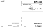
2.8 PC Health Status
" #?3D*9#
4**C$$ "#7=,&@@@'*
:*
Show H/W Monitor in POST
3sec
Current CPU FAN Speed
RPM
Current System FAN Speed
RPM
Vcore
V
+2.5V
V
+3.3V
V
+5.0V
V
+12.0V
Item Help
Menu Leve
V
: Move Enter :Select +/-/PU/PD :Value F10 :Save ESC :Exit F1 :General Help
F5 :Previous Values
F6 :Fail-Safe Defaults
F7 : Optimized Defaults
&%*7
5,' '+!!'A*!*
!
!&+
;!
+',,!!)
&
'!*
#"&,
%
2
$ C *$ % $
$
2
$ C *$ % $
$
9CE13A9CE8389CEA3;9CE013;9
8!!'9
+
'
&&=
Chapter 2
BIOS Setup
2.9 Load Optimized Defaults
< !! OP ! ' + ,'
&
+ =: * '!!
+!'
" #!3.(4,
4**C$$ "#7=,&@@@'*
Standard CMOS Features
PC Health Status
Advanced BIOS Features
Load Optimized Defaults
Advanced Chipset Features
Set Supervisor Password
Integrated Peripherals
Set User Password
Power Management Setup
Set User Password
Load Optimized Defaults
(Y/N) ? N
PnP/PCI Configurations
Save & Exit Setup
Exit Without Saving
Esc : Quit
F9: Menu in BIOS
F10 : Save & Exit Setup
: Select Item
Load Optimized Defaults
!!+ UKI &! 45; &,
)
! , '! !
=A ''
,'
!!' !
&&7
Chapter 2
BIOS Setup
2.10 Set Supervisor/User Password
" #0;3+*&
4**C$$ "#7=,777'*
Standard CMOS Features
PC Health Status
Advanced BIOS Features
Load Optimized Defaults
Advanced Chipset Features
Set Supervisor Password
Integrated Peripherals
Set User Password
Power Management Setup
Save & Exit Setup
PnP/PCI ConfigurationsEnter Password :Exit Without Saving
Esc : Quit
F9: Menu in BIOS
F10 : Save & Exit Setup
: Select Item
Change / Set / Disable Password
<!!,A,*+'!!
+*
!
!!!
+
!!*&
,
/*1<-
!!*&A +
!A
& !!OP !!*&
**
)!& !!*&,'(;''K
* = !-& ,' !!*& !!*& +
& !!
OP K '
! !! OP = ! & !!*& &!
= !!*&A L! !! OP * ' & !!*& $ '!!
+ * ,' *! &!
= !!*&
; !!*& ! &!
=&A !!' * = & !
,
&+@
Chapter 2
BIOS Setup
1<-15
5,!B!'C
; ,45;
! (A
*= ' &, !!*&)'!!'!=&
'
5,!B C
; ,45;
(A*= ' &* &+
Chapter 2
BIOS Setup
2.11 Save & Exit Setup
" #003+56
4**C$$ "#7=,&@@@'*
Standard CMOS Features
PC Health Status
Advanced BIOS Features
Load Optimized Defaults
Advanced Chipset Features
Set Supervisor Password
Integrated Peripherals
Set User Password
Power Management
Setupto CMOS and Exit
Save(Y/N)
& Exit?Setup
SAVE
Y
PnP/PCI Configurations
Exit Without Saving
Esc : Quit
F9: Menu in BIOS
F10 : Save & Exit Setup
: Select Item
Save Data to CMOS
VKV* &!
)!! )
(;
$(
V?V* &+&
Chapter 2
BIOS Setup
2.12 Exit Without Saving
" #01367+#
4**C$$ "#7=,&@@@'*
Standard CMOS Features
PC Health Status
Advanced BIOS Features
Load Optimized Defaults
Advanced Chipset Features
Set Supervisor Password
Integrated Peripherals
Set User Password
Power Management Setup
Set User Password
Quit Without Saving (Y/N)
?N
PnP/PCI Configurations
Save & Exit Setup
Exit Without Saving
Esc : Quit
F9: Menu in BIOS
F10 : Save & Exit Setup
: Select Item
Abandon all Datas
VKV* *!
)+(;$(
V?V* &++
Chapter 3
Software Setup
3. Software Setup
6?!2N
$3$ 3
-C$"*'?A?#
3.1 Software List
Category
Description
Platform
Location in CD
VIA Service Pack
VIA 4 IN 1 driver includes(VIA
Registry (ACPI) Driver/VIA
AGP VxD driver /VIA ATAPI
Vendor Support Driver/VIA PCI
IRQ Miniport Driver )
Windows
95/98/NT 4.0
\Mb_drv\Service
(4 In1) *
four system drivers to improve
the performance and maintain
the stability of system using
VIA chipset.
VIA Hardware
Monitor *
VIA Hardware Monitor is a
Windows 95/98 \Mb_drv\Sysdiag
self-diagnostic system for PC.
HighPoint XStore
Pro *
Install the drivers to support
Ultra DMA mode Hard Drive.
Windows 95/98
\Mb_drv\XStore
VIA AC97 Audio*
Install the driver to enable the
VIA AC97 Audio Device
DOS, Windows
95/98/NT4.0/
WIN2000
\Audio\VIA
Aureal Votex
Au8810 Audio*
Install the driver to enable the
Aureal Audio device
WIN9X/NT4.0
WIN2000
\Audio\Aureal
Creative SB PCI128 Install the driver to enable the
Audio*
Creative Audio Device
WIN9X/NT4.0
WIN2000
\Audio\Creative
Award Flash Utility
Used for updating BIOS.
3-1
\Flash
Chapter 3
Software Setup
3.2 Software Installation
< )&
!
*3
&A8)85!
"$@%A
& , 8) 8 !! !
!' '' !& &)!
)
#
The drivers can be installed from CD by using CD Installation
Utility:
K !' 8) 8 8;( &) & 5!
* 8) 8 5!
& = !+
'! ! - + * )- !' !,!
#
The drivers CAN NOT be installed directly from CD by using
CD Installation Utility:
!
&$8(@
&&('&
8
+&)!U
&,5?$>>@$8(@,!
&
&)&8)8!
&)!
3-2
Chapter 3
Software Setup
3.3 Using Software
#
In general, you can get more detailed information in the on-line
help or readme for the softwares.
#
Using VIA Hardware Monitor
$,!!
&A
,*!A !
81=2
A
'
3-3
Chapter 3
Software Setup
,*+ ,+! '
,95$ 2
&*
(5 A
+!'
'
&' ,'
9
+A
! &A
&
' A , :
' 5, ! ='
!
A !) ''&
3-4
Chapter 4
Trouble Shooting
4. Trouble Shooting
!"#$
? *!!'
*+&!'
A,
!& *
! &!5&
+-=
&&!
(
. 2(
(./(2
Power cable is unplugged. Visually inspect power
cable.
Make sure power cable is
securely plugged in.
Defective power cable.
Visual inspection, try
another cable.
Replace cable.
Power supply failure.
Power cable and wall
Contact technical support.
socket are OK, but system
is still dead.
Faulty wall outlet; circuit
Plug in device known to
work in socket and test.
Breaker or fuse blown.
4-1
Use different socket,
repair outlet, reset circuit
breaker or replace fuse.
Chapter 4
Trouble Shooting
!"#$
!' ) G=
& +! A * &
+! A &
&)!! +
(
. 2(
Expansion card is partially Turn off computer. Take
dislodged from expansion cover off system unit.
slot on the motherboard. Check all expansion cards
to ensure they are
securely seated in slots.
(./(2
Using even pressure on
both ends of the
expansion card, press
down firmly on expansion
card.
Defective floppy disk drive Turn system off.
Contact Technical
or tape drive.
Disconnect the cables
Support.
from one of the floppy
drives. Turn on the floppy
drives. Turn on the
system, check to see if the
keyboard operates
normally. Repeat until you
have located defective
unit.
Defective expansion card. Turn computer off.
Remove an expansion
card.
4-2
Make sure expansion
card is secure in
expansion socket.
Chapter 4
Trouble Shooting
!"#$
!'&!=,'
&&!-&)A
==&,',
(
. &!-&)
2(
(./(2
Connector between hard
drive and system board
unplugged.
When attempting to run
the FDISK utility described
in the HARD DISK section
of this manual you get a
message, INVALID
DRIVE SPECIFICATION.
Check cable running from
disk to disk controller
board. Make sure both
ends are securely plugged
in; check the drive type in
the Standard CMOS
Setup (see HARD DISK
section of this manual).
Damaged Hard Disk or
Disk Controller.
Format hard disk; if
unable to do so the hard
disk may be defective.
Contact Technical
Support.
Hard Disk directory or
FAT is scrambled.
Run the FDISK program,
format the hard drive (see
HARD DRIVE section of
manual). Copy data that
was backed up onto Hard
Drive.
Backing up the hard drive
is extremely important. All
Hard Disk are capable of
breaking down at any
time.
!"#$
!'=!,', 8!-2
&&!-
=
&
&
=!&==+,'2
&8!-!' !!=
(
. Hard Disk boot program
has been destroyed.
2(
!
(./(2
A number of causes could Back up data and
be behind this.
applications files.
Reformat the Hard Drive
as described in the Hard
Drive section of this
manual. Re-install
applications and data
using backup disks.
4-3
Chapter 4
Trouble Shooting
!"#$
'!!
+ &+ B; ?; ;?8C '!!
+! *+
&
=)&
(
. 2(
A number of causes could Use a file by file backup
be behind this.
instead of an image
backup in order to backup
the Hard Disk.
(./(2
Back up any salvageable
data. Then low level
format, partition, and high
level format the hard drive
(see Hard Disk section of
this manual for
instructions). Re-install all
saved data when
completed.
!"#$
8!-,'
&54(1* *!!!'
(
. 2(
(./(2
The IBM PS/2 uses a
IBM PS/2 disk format will Format disk in the AT type
different format than other not work in an AT type
computer insert disk into
computers.
computer.
the IBM PS/2 and copy
the files you wish.
4-4
Chapter 4
Trouble Shooting
!"#$
$,!
+
: !
&"*-
&A
&)
&A%!!'
+*-! (
. No power to monitor.
2(
All or part of the system
may be inoperable. The
new card may work but a
mouse or COM port may
not work.
(./(2
Change the interrupt or
RAM address on the new
expansion card. See the
documentation that came
with the new card in order
to change pin settings.
Many expansion devices
come with proprietary
software that will assist
you in doing this.
!"#$
'!!
+!
!B5)
&,+
CB(;
C
(
. Incorrect information
entered into the
configuration (setup)
program.
2(
Check the configuration
program. Replace any
incorrect information.
4-5
(./(2
Review system’s
equipment . Make sure
correct information is in
setup.
Chapter 4
Trouble Shooting
!"#$
!=
-
(
. 2(
(./(2
No power to monitor.
Check the power
connectors to monitor and
to system. Make sure
monitor is connected to
display card, change I/O
address on network card if
applicable.
Monitor not connected to
computer.
See instructions above.
Network card I/O address
conflict.
See instructions above.
!"#$
(
. 2(
(./(2
Memory problem, display
card jumpers not set
correctly.
Reboot computer.
Reinstall memory, make
sure that all memory
modules are installed in
correct sockets. Check
jumper and switch
settings on display card.
See display card section
for information on
settings.
Computer virus.
Use anti-virus programs
(mcAfee, E-Prot, etc) to
detect and clean viruses.
4-6
Chapter 4
Trouble Shooting
!"#$
+!=
- &
(
. 2(
Screen saver is enabled.
(./(2
Disable screen saver.
!"#$
G=
&,
(
. 2(
Keyboard is disconnected.
(./(2
Reconnect keyboard.
Check keys again, if no
improvement replace
keyboard.
!"#$
?!
(
. 2(
(./(2
Faulty Monitor.
If possible, connect
monitor to another
system. If no color replace
monitor.
CMOS incorrectly set up.
Call technical support.
!"#$
&)+!
!
(
. 2(
Floppy Drive cable not
connected correctly.
(./(2
Reconnect floppy cable
making sure PIN1 on the
Floppy Drive corresponds
with PIN1 on Floppy cable
connector.
4-7
Chapter 4
Trouble Shooting
!"#$
&+&)$
(
. 2(
(./(2
Bad floppy disk.
Try new floppy disk
Floppy disk not formatted.
Format floppy disk (type
FORMAT A:type
ENTER)>.
!"#$
&),
(
. 2(
(./(2
SETUP program does not
have correct information.
Boot from drive A: using
DOS system disk. Input
correct information to
SETUP program.
Hard Drive cable not
connected properly.
Check Hard Drive cable.
!"#$
=!!'
,!
+!&
&&)
(
. 2(
(./(2
Master/Slave jumpers not
set correctly.
Set Master/Slave jumpers
correctly.
Hard Drives not
compatible / different
manufacturers.
Run SETUP program and
select correct drive types.
Call Drive manufacturers
for compatibility with other
drives.
4-8
Chapter 4
Trouble Shooting
!"#$
(!!+ +!!'
&&)
(
. 2(
CMOS setup has been
changed.
(./(2
Run setup and select
correct drive type.
!"#$
-!&,
(
. 2(
Keys jammed or
defective.
(./(2
Replace keyboard.
!"#$
G=
&!-&A-!,
(
. 2(
Keyboard is locked.
(./(2
Unlock keyboard.
4-9
03/08/2000
MADE IN TAIWAN
R.O.C.